EP3330448B1 - Device and method for connecting two components in a certain relative orientation and concrete structure created using the same - Google Patents
Device and method for connecting two components in a certain relative orientation and concrete structure created using the same Download PDFInfo
- Publication number
- EP3330448B1 EP3330448B1 EP17204467.9A EP17204467A EP3330448B1 EP 3330448 B1 EP3330448 B1 EP 3330448B1 EP 17204467 A EP17204467 A EP 17204467A EP 3330448 B1 EP3330448 B1 EP 3330448B1
- Authority
- EP
- European Patent Office
- Prior art keywords
- sleeve
- bolt
- section
- end section
- components
- Prior art date
- Legal status (The legal status is an assumption and is not a legal conclusion. Google has not performed a legal analysis and makes no representation as to the accuracy of the status listed.)
- Active
Links
- 238000000034 method Methods 0.000 title claims description 9
- 238000006073 displacement reaction Methods 0.000 claims description 8
- 230000002787 reinforcement Effects 0.000 claims description 7
- 229910000831 Steel Inorganic materials 0.000 claims description 5
- 238000003780 insertion Methods 0.000 claims description 5
- 230000037431 insertion Effects 0.000 claims description 5
- 239000010959 steel Substances 0.000 claims description 5
- 230000003014 reinforcing effect Effects 0.000 claims description 4
- 238000003466 welding Methods 0.000 claims description 3
- 238000004026 adhesive bonding Methods 0.000 claims description 2
- 238000010276 construction Methods 0.000 claims description 2
- 239000007787 solid Substances 0.000 claims description 2
- 239000000463 material Substances 0.000 description 8
- 238000013461 design Methods 0.000 description 4
- 238000009434 installation Methods 0.000 description 4
- 230000015572 biosynthetic process Effects 0.000 description 3
- 239000004570 mortar (masonry) Substances 0.000 description 3
- 238000009415 formwork Methods 0.000 description 2
- 238000004519 manufacturing process Methods 0.000 description 2
- 239000011343 solid material Substances 0.000 description 2
- 230000006978 adaptation Effects 0.000 description 1
- 150000001875 compounds Chemical class 0.000 description 1
- 238000005260 corrosion Methods 0.000 description 1
- 230000007797 corrosion Effects 0.000 description 1
- 230000001419 dependent effect Effects 0.000 description 1
- 238000005538 encapsulation Methods 0.000 description 1
- 238000005516 engineering process Methods 0.000 description 1
- 230000008014 freezing Effects 0.000 description 1
- 238000007710 freezing Methods 0.000 description 1
- 239000011796 hollow space material Substances 0.000 description 1
- 229910001220 stainless steel Inorganic materials 0.000 description 1
- 239000010935 stainless steel Substances 0.000 description 1
- 238000012549 training Methods 0.000 description 1
- 238000012546 transfer Methods 0.000 description 1
- 230000007704 transition Effects 0.000 description 1
- XLYOFNOQVPJJNP-UHFFFAOYSA-N water Substances O XLYOFNOQVPJJNP-UHFFFAOYSA-N 0.000 description 1
Images


Classifications
-
- E—FIXED CONSTRUCTIONS
- E04—BUILDING
- E04B—GENERAL BUILDING CONSTRUCTIONS; WALLS, e.g. PARTITIONS; ROOFS; FLOORS; CEILINGS; INSULATION OR OTHER PROTECTION OF BUILDINGS
- E04B1/00—Constructions in general; Structures which are not restricted either to walls, e.g. partitions, or floors or ceilings or roofs
- E04B1/38—Connections for building structures in general
- E04B1/41—Connecting devices specially adapted for embedding in concrete or masonry
-
- E—FIXED CONSTRUCTIONS
- E04—BUILDING
- E04B—GENERAL BUILDING CONSTRUCTIONS; WALLS, e.g. PARTITIONS; ROOFS; FLOORS; CEILINGS; INSULATION OR OTHER PROTECTION OF BUILDINGS
- E04B1/00—Constructions in general; Structures which are not restricted either to walls, e.g. partitions, or floors or ceilings or roofs
- E04B1/38—Connections for building structures in general
- E04B1/48—Dowels, i.e. members adapted to penetrate the surfaces of two parts and to take the shear stresses
- E04B1/483—Shear dowels to be embedded in concrete
-
- E—FIXED CONSTRUCTIONS
- E04—BUILDING
- E04B—GENERAL BUILDING CONSTRUCTIONS; WALLS, e.g. PARTITIONS; ROOFS; FLOORS; CEILINGS; INSULATION OR OTHER PROTECTION OF BUILDINGS
- E04B1/00—Constructions in general; Structures which are not restricted either to walls, e.g. partitions, or floors or ceilings or roofs
- E04B1/003—Balconies; Decks
Definitions
- the present invention relates to a device for connecting two components in a specific relative orientation with a mandrel and a first sleeve, wherein the first sleeve embedable edge flush in one of the two components and the mandrel with a first end portion in this first sleeve inserted and with his opposite, second end portion is formed for engagement in the other concrete component.
- the present invention further relates to a method for connecting two components by means of such a device in a certain relative orientation and a structure with two components of concrete connected by means of such a device in a certain relative orientation.
- Devices and methods of the type mentioned are used, for example, to align two adjoining each other at the same height balcony precast slabs, which are each connected only on one side to a building and projecting therefrom, to each other.
- the balcony slabs tend to lower under their weight to their unconnected side, with a different reduction leads to an undesirable step formation at the transition between the balcony slabs.
- With devices of the type considered can be prevented by the two components are held by the mandrel in the desired relative orientation.
- the mandrel serves merely as constructive support, i. he does not have to absorb or transfer particularly large forces.
- the devices in question are also used to form a precast wall in a desired orientation on a foundation, a bottom wall or a ceiling to fix against transverse displacements. In most cases, several such devices are used in the longitudinal direction of the precast wall. With wider balcony slabs this may also be necessary.
- the tolerances to be complied with are so small that it is not possible, already in the precast plant, to provide each sleeve with two sleeves facing each other, in which the mandrels at the installation site would simply have to be inserted.
- the recess is poured with a spout material and so said end portion fixed therein.
- the formation of cracks by shrinkage of the spout material during curing is counteracted by using a swellable mortar. This procedure has several disadvantages.
- the recess In balcony slabs, the recess must be open to the top, so that in the finished state, the spout material in the remaining material of the balcony slabs is visible. The look is not optimal.
- the encapsulation sites are also susceptible to freezing conditions. Even when using swellable mortar as a pouring material cracks may form, through which water can penetrate and possibly cause corrosion of reinforcements in the component. The mortar can only be applied at appropriate temperatures. It is necessary to wait until the pouring material has hardened until it can continue to work. Previously, supports that hold the components in the desired orientation relative to each other can not be removed.
- the EP 0059171 A1 describes a mandrel and sleeve for receiving and transmitting a transverse force.
- a connecting element for adjacent components in particular concrete, sees EP 0059171 A1 a sleeve to be inserted in a component and a mandrel embedded in the other component, which penetrates the sleeve and is displaceable in its longitudinal axis and also has a lateral movement margin transverse to the direction of force, for casual adaptation to different expansions and shrinkages of the two components .
- Mandrel and sleeve are provided at the outer end of their part to be inserted with reinforcements. The reinforcements work where the load is greatest and rises sharply towards a component edge.
- the invention has as its object to provide a device of the type considered, which avoids the disadvantages mentioned and to provide a method for aligning two components with each other with such a device and a structure provided therewith with two concrete components, which are aligned therewith.
- a device having the features of claim 1.
- This is therefore characterized in that it comprises a second sleeve, which can be embedded in the other component and in which the mandrel with its second end portion can be inserted, that of Mandrel with its first end portion in the first sleeve is rotatable about a first axis, that the mandrel in the other sleeve in a plurality of rotational positions with respect to a second axis inserted, but in the inserted state in the respective rotational position is rotationally fixed, that the mandrel in at least one the two sleeves is displaceable transversely to its respective axis, and that the second axis is aligned with lateral offset parallel to the first axis.
- the inventive design allows a prior installation of sleeves in both components, in which the mandrel at the installation needs to be inserted only in each case.
- the two sleeves need not necessarily be exactly aligned with each other in the desired alignment of the two components.
- the mutual offset of the two sleeves can in particular be greater than the play of the two end sections in their respective sleeves.
- the inventive design allows existing tolerances with respect to the alignment of the two components by simply rotating and / or moving the mandrel in the first sleeve can be compensated in a suitable rotational position.
- the complex and time-consuming pouring of the second end portion of the mandrel is eliminated with the disadvantages and problems caused thereby.
- the inventive method is characterized by the following steps: inserting the mandrel with its first end portion in the first, embedded in the first component sleeve; Partial merging of the two components in the desired orientation; Rotating and / or translating the mandrel with its end portion in the first sleeve until its second end portion is flush with the second sleeve; Inserting the second end portion in the second sleeve by longitudinal displacement of the mandrel and / or further merging of the two components to a desired Mass.
- the inventive construction with two by means of a device according to the invention in a desired relative orientation interconnected components made of concrete is characterized in that the first sleeve in the one component and the second sleeve in the second component poured into the concrete and the mandrel with its end portions in the two sleeves is inserted.
- the first end portion of the mandrel is round in cross section. He can thereby take in the first sleeve without any restrictions any rotational position.
- the first sleeve is preferably rectangular in cross section. This allows a displacement of the first end portion of the mandrel in the first sleeve in a transverse direction, namely along the longer rectangle side. In this case, when the diameter of the first end portion of the mandrel is approximately equal to the width of the rectangular cross section of the first sleeve, a largely backlash-free connection of the two components in the desired alignment is achieved.
- the second end portion of the mandrel is preferably formed in cross section as a regular n-corner. Such a shape is rotationally symmetric with respect to n discrete rotational positions.
- the second end portion of the mandrel in cross-section may in particular be hexagonal.
- the first end section of the mandrel is longer in each case in the insertion direction, preferably 2 to 3 times as long, like its second end section.
- the mandrel engages thereby still in the first sleeve when inserted into the second sleeve and thereby do not fall out during assembly.
- the material suitable for the mandrel is steel, wherein the mandrel may be made in solid material or as a hollow profile. Manufacturing technology, the two end portions of the mandrel may be connected to each other by welding, in particular by friction welding, or by gluing.
- the second sleeve in a front-side section has a plate with an opening which is a regular m-shaped cross-section.
- the number m of the corners should be equal to or greater than the number n of the cross section of the second end portion of the mandrel.
- the opening in the plate is hexagonal in cross-section, but preferably dodecagonal. In the latter case, the second end portion of the mandrel in the second sleeve can take twelve different, discrete rotational positions, which is sufficient in most applications to align the two components finely.
- the second sleeve is designed so that it widens in the insertion direction behind the front panel.
- the opening in the second plate can be dimensioned with less clearance for optimum fixation of the rotational position of the mandrel.
- the front plate of the second sleeve is preferably a steel plate to which reinforcing bars are attached as a back-up reinforcement.
- the second end portion of the mandrel in the second sleeve could be displaceable transversely to its second axis, either alternatively to a displacement of its first end portion in the first sleeve or in addition.
- Fig. 1 shows a device according to the invention with a first sleeve 10, a second sleeve 20 and a mandrel 30 with a view of the front of the first sleeve and the back of the second sleeve.
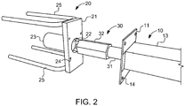
- Fig. 2 shows the three parts in the opposite direction.
- the first sleeve 10 has a front plate 11 with an opening 12 and an adjoining sleeve body 13, which is closed on the back.
- the first sleeve 10, but at least the opening 12 and the sleeve body 13, are rectangular in cross section, wherein the cross section of the sleeve body 13 preferably corresponds to the cross section of the opening 12 in the front panel 11.
- the front panel 11 is provided with four holes 14 for attachment to the inside of a concrete formwork by nailing or the like.
- the second sleeve 20 also has a front plate 21 with an opening 22 and an adjoining, rear closed sleeve body 23.
- the opening 22 in the front plate 21 is a regular polygonal cross-section with twelve corners.
- the sleeve body 23 is round and slightly widened in cross-section with respect to the cross section of the opening 22.
- the front plate 21 is made of steel and solid as the front plate 11 of the first sleeve 10.
- Reinforcing bars 25 are welded on the rear side as a repulsive reinforcement.
- Four holes 24 also allow attachment of the second sleeve 20 by nailing or the like to the inside of a concrete formwork.
- the in Fig. 3 mandrel 30, shown separately, has a first end portion 31 of circular cross section with respect to a first axis and a second end portion 32, the cross section of which is a regular polygon having six corners with respect to a second axis.
- the cross sections of the two end portions 31 and 32 are dimensioned such that they can be inserted into the sleeves 10 and 20, respectively.
- the insertion directions are in each case according to the axes and aligned.
- the FIGS. 1 and 2 show the mandrel 30 with its end portion 31 already inserted a little way into the first sleeve 10.
- the first end portion 31 of the mandrel 30 is not in alignment with its second end portion 32.
- the axes and the two end portions 31 and 32 are laterally offset from each other slightly, while aligned parallel to each other.
- the first end portion 31 of the mandrel is displaceable in this transversely to its axis along the longer sides of the rectangle, preferably by a multiple of its diameter.
- the shorter rectangular sides of the rectangular cross-section of the sleeve 10 are dimensioned so that the mandrel 30 has little play between them.
- the second, in cross-section hexagonal end portion 32 is dimensioned so that it also engages with little play in the second sleeve 20. Due to its hexagonal shape of the second end portion can be inserted in twelve different rotational positions, because of the small game but only in these twelve rotational positions in the opening 22 in the front panel 21 of the second sleeve. In the inserted state, the second end portion 32 of the mandrel 30 in the second sleeve 20 is rotationally fixed in one of the twelve possible rotational positions.
- Fig. 4 shows a kind of snapshot during assembly of the mandrel 30 in the connection of two components 40 and 50, which may be, for example, two cuboid concrete balcony slabs.
- two components 40, 50 are in Fig. 4 only opposing, parallel aligned end faces shown. Flanking at these end faces, a first sleeve 10 and a second sleeve 20 are each embedded in the concrete and indeed by pouring in the manufacture of the components 40 and 50, for example in a precast plant.
- the component 40 mounted in its desired position.
- the mandrel 30 is inserted with its first end portion 31 into the first sleeve in the first component 40, and preferably so far that only its second end portion 32 is visible.
- the second component 50 in the desired relative orientation to the first component 40 so far brought to this that its end face just does not touch the projecting second end portion 32 of the mandrel 30.
- This must now be pulled out of the first sleeve 10 a piece and inserted with its second end portion 32 in the second sleeve 20.
- the mutual offset of the two sleeves can first be compensated by turning and / or transverse displacement of the mandrel 30 in the first sleeve 10 , This works because, as described above, the two end portions 22 and 32 of the mandrel 30 are not in alignment with each other, but offset from one another laterally. After this compensation, the mandrel 30 is inserted with its second end portion 32 in the second sleeve 20.
- the second component 50 can be brought closer to the first component 40 until they touch each other or until a desired joint dimension between the two components is reached.
- any supports can be removed as a rule and further work can be carried out immediately.
- further work by the inventive compound is not hindered.
- a first Sleeve of an inventive device in the lower component for example, be installed by pouring into concrete.
- a second sleeve of the device according to the invention is already installed in the precast plant at a corresponding position.
- the dimensions suitable for the mandrel 30, in particular for the diameters of its two end sections 31, 32, depend on the expected load. If a stainless steel is used for the mandrel and the mandrel is made of solid material, suitable diameters for its first end portion 31 are in the range of 12-50 mm and for its second end portion 32 in the range of 16-80 mm. In the case of hollow material with a wall thickness in the range of 2 - 15 mm suitable diameter for its first end portion 31 in the range of 12 - 50 mm and for its second end portion 32 in the range of 16 - 80 mm. The mutual offset of the two end portions 31, 32 may be in the range of 3 - 30 mm.
- Suitable diameters for its first end portion 31 are in the range of 12-50 mm and for its second end portion 32 in the range of 16-80 mm. With an offset of 5 mm, for example, tolerances in the alignment of the two sleeves of up to 10 mm can be compensated. For the longer rectangular sides of the rectangular first sleeve 10 or its opening 12, lengths in the range 80-500 mm are suitable.
- the first end portion 31 of the mandrel 30 should be longer than its second end portion 32 a, so that the already inserted with its first end portion 31, the first sleeve 10 mandrel 30 when it is pulled out of this again a piece to its second end portion 32 in the second sleeve 20 to be inserted, still can remain inserted in the first sleeve 10.
- a length for the first end portion 31 are suitable 75-490 mm and the length of the second end portion 32 are 40-200 mm suitable. The lengths of the two sleeves 10, 20 are to be selected accordingly.
- the front plate 21 of the second sleeve 20 must be able to absorb any rotational forces exerted by the mandrel 30. It should have dimensions of 30 - 140 mm x 80-200 mm x 4-80 mm. Suitable for the reinforcing bars 25 of the back-up reinforcement are diameters of 8-25 mm and lengths of 150-1000 mm.
- a hexagonal configuration of the second end portion 32 of the mandrel 30 in combination with a dodecagonal configuration of the opening 22 in the second sleeve 20 is sufficient for most applications to provide a sufficiently fine balance of tolerances in flight of two sleeves 10 to be joined together. 20 to enable. By other geometries, in particular by more or fewer corners, the fineness of the compensation can be further increased or reduced.
- the "corners”, both on the mandrel and on the sleeve, could also be rounded so that the end portion of the mandrel in cross section, for example, an oval shape and the sleeve receives the cross section of a multi-leaved flower or the like.
- the second end section of the mandrel in the second sleeve could be displaceable transversely to its second axis.
- the width of the rectangular cross section should correspond approximately to the hexagon size. This would be possible by an example in cross-section rectangular design of the second sleeve or its front plate at the same time polygonal, for example, again hexagonal training of second end portion of the mandrel.
- the width of the rectangular cross section should correspond approximately to the hexagon size. If only the second end portion of the mandrel in the second sleeve is displaceable transversely to its second axis, the first sleeve could be a round sleeve.
Description
Die vorliegende Erfindung betrifft eine Vorrichtung zur Verbindung von zwei Bauteilen in einer bestimmten relativen Ausrichtung mit einem Dorn und einer ersten Hülse, wobei die erste Hülse randbündig in einem der beiden Bauteile einbettbar und der Dorn mit einem ersten Endabschnitt in diese erste Hülse einsteckbar und mit seinem gegenüberliegenden, zweiten Endabschnitt zum Eingriff in das andere Betonbauteil ausgebildet ist.The present invention relates to a device for connecting two components in a specific relative orientation with a mandrel and a first sleeve, wherein the first sleeve embedable edge flush in one of the two components and the mandrel with a first end portion in this first sleeve inserted and with his opposite, second end portion is formed for engagement in the other concrete component.
Die vorliegende Erfindung betrifft weiter ein Verfahren zur Verbindung von zwei Bauteilen mittels einer solchen Vorrichtung in einer bestimmten relativen Ausrichtung sowie ein Bauwerk mit zwei mittels einer solchen Vorrichtung in einer bestimmten relativen Ausrichtung miteinander verbundenen Bauteilen aus Beton.The present invention further relates to a method for connecting two components by means of such a device in a certain relative orientation and a structure with two components of concrete connected by means of such a device in a certain relative orientation.
Vorrichtungen und Verfahren der genannten Art werden beispielsweise eingesetzt, um zwei auf gleicher Höhe aneinander anschliessende Balkon-Fertigteilplatten, die jeweils nur einseitig an ein Gebäude angeschlossen sind und von diesem aus vorkragen, aufeinander auszurichten. Die Balkonplatten tendieren unter ihrem Gewicht dazu, sich zu ihrer nicht angeschlossenen Seite hin abzusenken, wobei eine unterschiedliche Absenkung zu einer unerwünschten Stufenbildung am Übergang zwischen den Balkonplatten führt. Mit Vorrichtungen der betrachteten Art lässt sich das verhindern, indem die beiden Bauteile durch den Dorn in der gewünschten relativen Ausrichtung gehalten werden. Der Dorn dient hierbei lediglich als konstruktive Unterstützung, d.h. er muss keine besonders grossen Kräfte aufnehmen bzw. übertragen.Devices and methods of the type mentioned are used, for example, to align two adjoining each other at the same height balcony precast slabs, which are each connected only on one side to a building and projecting therefrom, to each other. The balcony slabs tend to lower under their weight to their unconnected side, with a different reduction leads to an undesirable step formation at the transition between the balcony slabs. With devices of the type considered can be prevented by the two components are held by the mandrel in the desired relative orientation. The mandrel serves merely as constructive support, i. he does not have to absorb or transfer particularly large forces.
Die betrachteten Vorrichtungen kommen auch zum Einsatz, um eine Fertigteilwand in einer gewünschten Ausrichtung auf einem Fundament, einer unteren Wand oder einer Decke gegen Querverschiebungen zu fixieren. Meist kommen dabei in Längsrichtung der Fertigteilwand mehrere solcher Vorrichtungen zum Einsatz. Bei breiteren Balkonplatten kann das ebenfalls erforderlich sein.The devices in question are also used to form a precast wall in a desired orientation on a foundation, a bottom wall or a ceiling to fix against transverse displacements. In most cases, several such devices are used in the longitudinal direction of the precast wall. With wider balcony slabs this may also be necessary.
In der Regel sind die einzuhaltenden Toleranzen so gering, dass es nicht möglich ist, bereits im Fertigteilwerk in beiden aufeinander auszurichtenden Bauteilen einander gegenüberliegend jeweils Hülsen vorzusehen, in welche die Dorne am Einbauort einfach nur eingesteckt werden müssten. Das gilt in besonderem Masse beim gleichzeitigen Einsatz mehrerer Vorrichtungen. Entsprechend wird üblicherweise pro Dorn nur eine Hülse in einem der beiden Bauteile eingebettet und im anderen Bauteil dieser gegenüberliegend eine grössere Aussparung belassen, in welche der Dorn mit seinem vorstehend als zweiten bezeichneten Endabschnitt mit Spiel eingreifen kann. Nach Ausrichtung der beiden Bauteile aufeinander unter Ausnutzung dieses Spiels wird die Aussparung mit einem Ausgussmaterial ausgegossen und so der genannte Endabschnitt darin fixiert. Der Bildung von Rissen durch Schwinden des Ausgussmaterials beim Aushärten wird durch Verwendung eines quellfähigen Mörtels entgegengewirkt. Diese Vorgehensweise hat diverse Nachteile.In general, the tolerances to be complied with are so small that it is not possible, already in the precast plant, to provide each sleeve with two sleeves facing each other, in which the mandrels at the installation site would simply have to be inserted. This applies in particular to the simultaneous use of several devices. Accordingly, usually only one sleeve is embedded per mandrel in one of the two components and left in the other component of this opposite a larger recess, in which the mandrel can intervene with its above-referred to as the second end portion with play. After alignment of the two components to each other by utilizing this game, the recess is poured with a spout material and so said end portion fixed therein. The formation of cracks by shrinkage of the spout material during curing is counteracted by using a swellable mortar. This procedure has several disadvantages.
Bei Balkonplatten muss die Aussparung zu deren Oberseite hin offen sein, so dass im fertigen Zustand das Ausgussmaterial im übrigen Material der Balkonplatten sichtbar ist. Die Optik ist dadurch nicht optimal. Die Vergussstellen sind auch anfällig auf Frostzustände. Selbst bei Verwendung von quellfähigem Mörtel als Ausgussmaterial können sich Risse bilden, durch welche Wasser eindringen und gegebenenfalls Korrosion von Bewehrungen im Bauteil verursachen kann. Der Mörtel kann nur bei entsprechenden Temperaturen eingebracht werden. Bis zum Aushärten des Ausgussmaterials muss zugewartet werden, bis weiter gearbeitet werden kann. Vorher können auch Abstützungen, die die Bauteile in der gewünschten Ausrichtung relativ zueinander halten, nicht entfernt werden.In balcony slabs, the recess must be open to the top, so that in the finished state, the spout material in the remaining material of the balcony slabs is visible. The look is not optimal. The encapsulation sites are also susceptible to freezing conditions. Even when using swellable mortar as a pouring material cracks may form, through which water can penetrate and possibly cause corrosion of reinforcements in the component. The mortar can only be applied at appropriate temperatures. It is necessary to wait until the pouring material has hardened until it can continue to work. Previously, supports that hold the components in the desired orientation relative to each other can not be removed.
Bei der Verwendung der Vorrichtungen zur Ausrichtung einer Fertigteilwand auf einem darunter angeordneten Bauteil müssen Aussparungen für meist mehrere Dorne in diesem vorgesehen werden. Die Dorne müssen dann in die mit dem Ausgussmaterial bereits gefüllten Aussparungen eingedrückt werden, solange dieses noch ausreichend weich ist.When using the devices for aligning a prefabricated wall on a component arranged underneath recesses must be provided for a plurality of mandrels in this. The mandrels must then be pressed into the already filled with the spout material recesses, as long as this is still sufficiently soft.
Die
Die Erfindung stellt sich die Aufgaben, eine Vorrichtung der betrachteten Art zu schaffen, welche die genannten Nachteile vermeidet und ein Verfahren zur Ausrichtung von zwei Bauteilen aufeinander mit einer solchen Vorrichtung sowie ein damit versehenes Bauwerk mit zwei Betonbauteilen anzugeben, die damit aufeinander ausgerichtet sind.The invention has as its object to provide a device of the type considered, which avoids the disadvantages mentioned and to provide a method for aligning two components with each other with such a device and a structure provided therewith with two concrete components, which are aligned therewith.
Hinsichtlich der Vorrichtung wird diese Aufgabe gelöst durch eine Vorrichtung mit den Merkmalen des Patentanspruchs 1. Diese ist demnach dadurch gekennzeichnet, dass sie eine zweite Hülse umfasst, welche in dem anderen Bauteil einbettbar und in welche der Dorn mit seinem zweiten Endabschnitt einsteckbar ist, dass der Dorn mit seinem ersten Endabschnitt in der ersten Hülse um eine erste Achse drehbar ist, dass der Dorn in die andere Hülse in mehreren Drehstellungen bezüglich einer zweiten Achse einsteckbar, im eingesteckten Zustand in der jeweiligen Drehstellung jedoch drehfest fixiert ist, dass der Dorn in wenigstens einer der beiden Hülsen quer zu seiner jeweiligen Achse verschiebbar ist, und dass die zweite Achse mit seitlichem Versatz parallel zur ersten Achse ausgerichtet ist. Die erfindungsgemässe Ausbildung erlaubt einen vorgängigen Einbau von Hülsen in beide Bauteile, in welche der Dorn am Einbauort jeweils nur eingesteckt zu werden braucht. Die beiden Hülsen müssen bei der gewünschten Ausrichtung der beiden Bauteile nicht notwendig exakt miteinander fluchten. Der gegenseitige Versatz der beiden Hülsen kann insbesondere grösser sein als das Spiel der beiden Endabschnitte in ihren jeweiligen Hülsen. Durch die erfindungsgemässe Ausbildung können vorhandene Toleranzen bezüglich der Flucht der beiden Bauteile durch einfaches Drehen und/oder Verschieben des Dorns in der ersten Hülse in eine geeignete Drehstellung ausgeglichen werden. Das aufwendige und zeitraubende Ausgiessen des zweiten Endabschnitts des Dorns entfällt mit den dadurch verursachten Nachteilen und Problemen.With regard to the device, this object is achieved by a device having the features of claim 1. This is therefore characterized in that it comprises a second sleeve, which can be embedded in the other component and in which the mandrel with its second end portion can be inserted, that of Mandrel with its first end portion in the first sleeve is rotatable about a first axis, that the mandrel in the other sleeve in a plurality of rotational positions with respect to a second axis inserted, but in the inserted state in the respective rotational position is rotationally fixed, that the mandrel in at least one the two sleeves is displaceable transversely to its respective axis, and that the second axis is aligned with lateral offset parallel to the first axis. The inventive design allows a prior installation of sleeves in both components, in which the mandrel at the installation needs to be inserted only in each case. The two sleeves need not necessarily be exactly aligned with each other in the desired alignment of the two components. The mutual offset of the two sleeves can in particular be greater than the play of the two end sections in their respective sleeves. The inventive design allows existing tolerances with respect to the alignment of the two components by simply rotating and / or moving the mandrel in the first sleeve can be compensated in a suitable rotational position. The complex and time-consuming pouring of the second end portion of the mandrel is eliminated with the disadvantages and problems caused thereby.
Das erfindungsgemässe Verfahren ist entsprechend durch folgende Schritte gekennzeichnet: Einstecken des Dorns mit seinem ersten Endabschnitt in die erste, im ersten Bauteil eingebettete Hülse; teilweises Zusammenführen der beiden Bauteile in der gewünschten Ausrichtung; Drehen und/oder Querverschieben des Dorns mit seinem Endabschnitt in der ersten Hülse bis sein zweiter Endabschnitt mit der zweiten Hülse fluchtet; Einführen des zweiten Endabschnitts in die zweite Hülse durch Längsverschieben des Dorns und/oder weiteres Zusammenführen der beiden Bauteile bis auf ein gewünschtes Mass.The inventive method is characterized by the following steps: inserting the mandrel with its first end portion in the first, embedded in the first component sleeve; Partial merging of the two components in the desired orientation; Rotating and / or translating the mandrel with its end portion in the first sleeve until its second end portion is flush with the second sleeve; Inserting the second end portion in the second sleeve by longitudinal displacement of the mandrel and / or further merging of the two components to a desired Mass.
Das erfindungsgemässe Bauwerk mit zwei mittels einer erfindungsgemässen Vorrichtung in einer gewünschten relativen Ausrichtung miteinander verbundenen Bauteilen aus Beton ist dadurch gekennzeichnet, dass die erste Hülse in dem einen Bauteil und die zweite Hülse in dem zweiten Bauteil in den Beton eingegossen und der Dorn mit seinen Endabschnitten in die beiden Hülsen eingesteckt ist.The inventive construction with two by means of a device according to the invention in a desired relative orientation interconnected components made of concrete is characterized in that the first sleeve in the one component and the second sleeve in the second component poured into the concrete and the mandrel with its end portions in the two sleeves is inserted.
Bevorzugte Ausbildungen der erfindungsgemässen Vorrichtung sind in den abhängigen Ansprüchen 2 - 13 gekennzeichnet.Preferred embodiments of the inventive device are characterized in the dependent claims 2-13.
Demnach ist es bevorzugt, dass der erste Endabschnitt des Dorns im Querschnitt rund ist. Er kann dadurch in der ersten Hülse ohne Einschränkungen jede beliebige Drehstellung einnehmen.Accordingly, it is preferable that the first end portion of the mandrel is round in cross section. He can thereby take in the first sleeve without any restrictions any rotational position.
Die erste Hülse ist im Querschnitt bevorzugt rechteckig. Das ermöglicht eine Verschiebung des ersten Endabschnitts des Dorns in der ersten Hülse in einer Querrichtung, nämlich entlang der längeren Rechteckseite. Wenn in diesem Fall der Durchmesser des ersten Endabschnitts des Dorns annähernd der Breite des rechteckigen Querschnitts der ersten Hülse entspricht wird eine weitgehend spielfreie Verbindung der beiden Bauteile in der gewünschten Ausrichtung aufeinander erreicht.The first sleeve is preferably rectangular in cross section. This allows a displacement of the first end portion of the mandrel in the first sleeve in a transverse direction, namely along the longer rectangle side. In this case, when the diameter of the first end portion of the mandrel is approximately equal to the width of the rectangular cross section of the first sleeve, a largely backlash-free connection of the two components in the desired alignment is achieved.
Der zweite Endabschnitt des Dorns ist bevorzugt im Querschnitt als regelmässiges n-Eck ausgebildet. Eine solche Form ist rotationssymmetrisch bezüglich n diskreten Drehstellungen. Dabei kann der zweite Endabschnitt des Dorns im Querschnitt insbesondere sechseckig sein.The second end portion of the mandrel is preferably formed in cross section as a regular n-corner. Such a shape is rotationally symmetric with respect to n discrete rotational positions. In this case, the second end portion of the mandrel in cross-section may in particular be hexagonal.
Im Hinblick auf das erfindungsgemässe Verfahren ist es vorteilhaft, wenn der erste Endabschnitt des Dorns jeweils in Einsteckrichtung länger, vorzugsweise 2- bis 3-mal so lang, wie sein zweiter Endabschnitt ist. Der Dorn greift dadurch beim Einstecken in die zweite Hülse immer noch in die erste Hülse ein und dadurch bei der Montage nicht herausfallen.With regard to the method according to the invention, it is advantageous if the first end section of the mandrel is longer in each case in the insertion direction, preferably 2 to 3 times as long, like its second end section. The mandrel engages thereby still in the first sleeve when inserted into the second sleeve and thereby do not fall out during assembly.
Als Material für den Dorn geeignet ist Stahl, wobei der Dorn in Vollmaterial oder als Hohlprofil ausgeführt sein kann. Herstellungstechnisch können die beiden Endabschnitte des Dorns durch Schweissen, insbesondere durch Reibschweissen, oder auch durch Kleben miteinander verbunden sein.As the material suitable for the mandrel is steel, wherein the mandrel may be made in solid material or as a hollow profile. Manufacturing technology, the two end portions of the mandrel may be connected to each other by welding, in particular by friction welding, or by gluing.
Die zweite Hülse weist in einer bevorzugten Ausführungsform in einem frontseitigen Abschnitt eine Platte mit einer Öffnung auf, die im Querschnitt ein regelmässiges m-Eck ist. Die Anzahl m der Ecken sollte dabei gleich oder grösser als die Anzahl n des Querschnitts des zweiten Endabschnitts des Dorns sein. Entsprechend bevorzugt ist die Öffnung in der Platte im Querschnitt sechseckig, vorzugsweise jedoch zwölfeckig. Im letzteren Fall kann der zweite Endabschnitt des Dorns in der zweiten Hülse zwölf unterschiedliche, diskrete Drehstellungen einnehmen, was in den meisten Anwendungsfällen ausreicht um die beiden Bauteile fein aufeinander auszurichten.In a preferred embodiment, the second sleeve in a front-side section has a plate with an opening which is a regular m-shaped cross-section. The number m of the corners should be equal to or greater than the number n of the cross section of the second end portion of the mandrel. Correspondingly, preferably, the opening in the plate is hexagonal in cross-section, but preferably dodecagonal. In the latter case, the second end portion of the mandrel in the second sleeve can take twelve different, discrete rotational positions, which is sufficient in most applications to align the two components finely.
Gemäss einer weiteren bevorzugten Ausführungsform ist die zweite Hülse so ausgebildet, dass sie sich in Einsteckrichtung hinter der Frontplatte erweitert. Dadurch kann die Öffnung in der zweiten Platte mit geringerem Spiel zur optimalen Fixierung der Drehstellung des Dorns bemessen werden.According to a further preferred embodiment, the second sleeve is designed so that it widens in the insertion direction behind the front panel. As a result, the opening in the second plate can be dimensioned with less clearance for optimum fixation of the rotational position of the mandrel.
Die Frontplatte der zweiten Hülse ist bevorzugt eine Stahlplatte, an welcher Bewehrungseisen als Rückhängebewehrung befestigt sind.The front plate of the second sleeve is preferably a steel plate to which reinforcing bars are attached as a back-up reinforcement.
Grundsätzlich könnte auch der zweite Endabschnitt des Dorns in der zweiten Hülse quer zu seiner zweiten Achse verschiebbar sein, entweder alternativ zu einer Verschiebbarkeit seines ersten Endabschnitts in der ersten Hülse oder auch zusätzlich.In principle, the second end portion of the mandrel in the second sleeve could be displaceable transversely to its second axis, either alternatively to a displacement of its first end portion in the first sleeve or in addition.
Nachfolgend werden Ausführungsbeispiele der Erfindung erläutert.Hereinafter, embodiments of the invention will be explained.
Es zeigen jeweils perspektivisch:
- Fig. 1
- eine erfindungsgemässe Vorrichtung in einer ersten Ansicht;
- Fig. 2
- die Vorrichtung in einer zweiten Ansicht;
- Fig. 3
- den Dorn der Vorrichtung; und
- Fig. 4
- die Vorrichtung während der Verbindung von zwei Bauteilen.
- Fig. 1
- an inventive device in a first view;
- Fig. 2
- the device in a second view;
- Fig. 3
- the spike of the device; and
- Fig. 4
- the device during the connection of two components.
Der in
Durch den rechteckigen Querschnitt der ersten Hülse 10 ist der erste Endabschnitt 31 des Dorns in dieser quer zu seiner Achse entlang den längeren Rechteckseiten verschiebbar, vorzugsweise um ein Mehrfaches seines Durchmessers. Die kürzeren Rechteckseiten des rechteckigen Querschnitts der Hülse 10 sind demgegenüber so bemessen, dass der Dorn 30 zwischen ihnen nur wenig Spiel hat. Der zweite, im Querschnitt sechseckige Endabschnitt 32 ist so bemessen, dass er ebenfalls mit nur wenig Spiel in die zweite Hülse 20 eingreift. Durch seine sechseckige Form kann der zweite Endabschnitt in zwölf unterschiedlichen Drehstellungen, wegen dem geringen Spiel aber auch nur in diesen zwölf Drehstellungen, in die Öffnung 22 in der Frontplatte 21 der zweiten Hülse eingesteckt werden. Im eingesteckten Zustand ist der zweite Endabschnitt 32 des Dorns 30 in der zweiten Hülse 20 in einer der zwölf möglichen Drehstellungen drehfest fixiert.Due to the rectangular cross-section of the
Die relative Ausrichtung der Bauteile 40, 50 aufeinander kann während der Montage bei Bedarf mittels geeigneter Abstützungen (nicht dargestellt) erfolgen. Zur Verbindung von zwei Balkonplatten sollte insbesondere das zweite Bauteil auf einer Abstützung auf gleicher Höhe neben dem ersten, ggf. bereits fertig montierten Bauteil abgelegt und auf dieser Abstützung horizontal gegen das erste Bauteil verschoben werden können.The relative alignment of the
Nach einer Verbindung von zwei Bauteilen wie beispielsweise vorbeschrieben können allfällige Abstützungen in der Regel entfernt und weitere Arbeiten sofort durchgeführt werden. Jedenfalls werden weitere Arbeiten durch die erfindungsgemässe Verbindung nicht behindert.After a connection of two components such as described above, any supports can be removed as a rule and further work can be carried out immediately. In any case, further work by the inventive compound is not hindered.
Um eine Fertigteilwand in einer gewünschten Ausrichtung auf einem Fundament, einer unteren Wand oder einer Decke gegen Querverschiebungen zu fixieren, kann eine erste Hülse einer erfindungsgemässen Vorrichtung im unteren Bauteil beispielsweise durch Eingiessen in Beton eingebaut werden. In der Fertigteilwand wird an einer entsprechenden Position eine zweite Hülse der erfindungsgemässen Vorrichtung bereits im Fertigteilwerk eingebaut. Beim Aufrichten der Fertigteilwand wird der Dorne der erfindungsgemässen Vorrichtung in die erste Hülse eingesteckt und dann das Fertigbauteil mit einem Kran bis unmittelbar an diesen herangeführt und zwar bereits in seiner gewünschten Ausrichtung. Wie vorstehend beschrieben, kann dann ein gegenseitiger Versatz der ersten und zweiten Hülse durch Drehen und/oder Querverschieben des Dorns ausgeglichen werden. Danach kann die Fertigteilwand auf das untere Bauteil abgesenkt werden.To fix a prefabricated wall in a desired orientation on a foundation, a lower wall or a ceiling against transverse displacements, a first Sleeve of an inventive device in the lower component, for example, be installed by pouring into concrete. In the precast wall, a second sleeve of the device according to the invention is already installed in the precast plant at a corresponding position. When erecting the precast wall of the mandrels of the inventive device is inserted into the first sleeve and then the finished component with a crane brought up to this directly and indeed already in its desired orientation. As described above, then a mutual offset of the first and second sleeve can be compensated by turning and / or transverse displacement of the mandrel. Thereafter, the precast wall can be lowered onto the lower component.
Die für den Dorn 30 geeigneten Abmessungen insbesondere für die Durchmesser seiner beiden Endabschnitte 31, 32 richten sich nach der zu erwartenden Belastung. Wenn für den Dorn ein nichtrostender Stahl verwendet wird und der Dorn aus Vollmaterial besteht liegen geeignete Durchmesser für seinen ersten Endabschnitt 31 im Bereich von 12 - 50 mm und für seinen zweiten Endabschnitt 32 im Bereich von 16 - 80 mm. Im Falle von Hohlmaterial mit einer Wandstärke im Bereich von 2 - 15 mm liegen geeignete Durchmesser für seinen ersten Endabschnitt 31 im Bereich von 12 - 50 mm und für seinen zweiten Endabschnitt 32 im Bereich von 16 - 80 mm. Der gegenseitige Versatz der beiden Endabschnitte 31, 32 kann im Bereich von 3 - 30 mm liegen. Geeignete Durchmesser für seinen ersten Endabschnitt 31 liegen im Bereich von 12 - 50 mm und für seinen zweiten Endabschnitt 32 im Bereich von 16- 80 mm. Mit einem Versatz von 5 mm können beispielsweise Toleranzen in der Flucht der beiden Hülsen von bis zu 10 mm ausgeglichen werden. Für die längeren Rechteckseiten der rechteckigen ersten Hülse 10 bzw. ihrer Öffnung 12 sind Längen im Bereich 80 - 500 mm geeignet.The dimensions suitable for the
Der erste Endabschnitt 31 des Dorns 30 sollte länger als sein zweiter Endabschnitt 32 ein, damit der bereits mit seinem ersten Endabschnitt 31 die erste Hülse 10 eingesteckte Dorn 30, wenn er aus dieser wieder ein Stück weit herausgezogen wird, um mit seinem zweiten Endabschnitt 32 in die zweite Hülse 20 eingesteckt zu werden, immer noch in der ersten Hülse 10 eingesteckt bleiben kann. Als Länge für den ersten Endabschnitt 31 eignen sich 75 - 490 mm und als Länge für den zweiten Endabschnitt 32 sind 40 - 200 mm geeignet. Die Längen der beiden Hülsen 10, 20 sind entsprechend zu wählen.The
Die Frontplatte 21 der zweiten Hülse 20 muss durch den Dorn 30 gegebenenfalls ausgeübte Drehkräfte aufnehmen können. Sie sollte dazu Abmessungen von 30 - 140 mm x 80-200 mm x 4-80 mm aufweisen. Für die Bewehrungseisen 25 der Rückhängebewehrung geeignet sind Durchmesser von 8 - 25 mm und Längen von 150 -1000 mm geeignet.The
Eine sechseckige Ausbildung des zweiten Endabschnitts 32 des Dorns 30 in Kombination mit einer zwölfeckigen Ausbildung der Öffnung 22 in der zweiten Hülse 20 ist für die meisten Anwendungsfälle ausreichend, um einen genügend feinen Ausgleich bezüglich vorkommender Toleranzen in der Flucht von zwei miteinander zu verbindenden Hülsen 10, 20 zu ermöglichen. Durch andere Geometrien, insbesondere durch mehr oder weniger Ecken, kann die Feinheit des Ausgleichs weiter erhöht oder auch verringert werden. Die "Ecken", sowohl am Dorn als auch an der Hülse, könnten auch abgerundet sein, so dass der Endabschnitt des Dorns im Querschnitt beispielsweise eine ovale Form und die Hülse den Querschnitt einer mehrblättrigen Blume oder dergleichen erhält.A hexagonal configuration of the
Das vorbeschriebene Montageverfahren kann analog natürlich auch mit mehreren erfindungsgemässen Vorrichtungen gleichzeitig zur Verbindung von zwei Bauteilen angewendet werden.The above-described assembly method can analogously of course also be used with several inventive devices simultaneously for the connection of two components.
Wie bereits erwähnt, könnte grundsätzlich auch oder alternativ nur der zweite Endabschnitt des Dorns in der zweiten Hülse quer zu seiner zweiten Achse verschiebbar sein. Möglich wäre dies durch eine beispielsweise im Querschnitt rechteckige Ausbildung der zweiten Hülse oder der Öffnung in ihrer frontseitigen Platte bei gleichzeitig mehreckiger, zum Beispiel wieder sechseckiger Ausbildung des zweiten Endabschnitts des Dorns. Um auch hierbei weitgehende Spielfreiheit zu erreichen, sollte die Breite des rechteckigen Querschnitts etwa dem Sechskantmass entsprechen. Möglich wäre dies durch eine beispielsweise im Querschnitt rechteckige Ausbildung der zweiten Hülse oder ihrer frontseitigen Platte bei gleichzeitig mehreckiger, zum Beispiel wieder sechseckiger Ausbildung des zweiten Endabschnitts des Dorns. Um auch hierbei weitgehende Spielfreiheit zu erreichen, sollte die Breite des rechteckigen Querschnitts etwa dem Sechskantmass entsprechen. Sofern nur der zweite Endabschnitt des Dorns in der zweiten Hülse quer zu seiner zweiten Achse verschiebbar ist, könnte die erste Hülse eine Rundhülse sein.As already mentioned, in principle or alternatively only the second end section of the mandrel in the second sleeve could be displaceable transversely to its second axis. This would be possible by an example in cross-section rectangular design of the second sleeve or the opening in its front plate at the same time polygonal, for example, again hexagonal formation of the second end portion of the mandrel. In order to achieve extensive freedom of play, the width of the rectangular cross section should correspond approximately to the hexagon size. This would be possible by an example in cross-section rectangular design of the second sleeve or its front plate at the same time polygonal, for example, again hexagonal training of second end portion of the mandrel. In order to achieve extensive freedom of play, the width of the rectangular cross section should correspond approximately to the hexagon size. If only the second end portion of the mandrel in the second sleeve is displaceable transversely to its second axis, the first sleeve could be a round sleeve.
- 1010
- erste Hülsefirst sleeve
- 1111
- Frontplatte der ersten HülseFront panel of the first sleeve
- 1212
- Öffnung in der ersten FrontplatteOpening in the first front panel
- 1313
- Hülsenkörper der ersten HülseSleeve body of the first sleeve
- 1414
- Löcher in der Frontplatte der ersten HülseHoles in the front panel of the first sleeve
- 2020
- zweite Hülsesecond sleeve
- 2121
- Frontplatte der zweiten HülseFront panel of the second sleeve
- 2222
- Öffnung in der Frontplatte der zweiten HülseOpening in the front panel of the second sleeve
- 2323
- Hülsenkörper der zweiten HülseSleeve body of the second sleeve
- 2424
- Löcher in der Frontplatte der zweiten HülseHoles in the front panel of the second sleeve
- 2525
- Bewehrungseisenrebar
- 3030
-
Dorn 30
Thorn 30 - 3131
- erster Endabschnitt des Dornsfirst end portion of the spine
- 3232
- zweiter Endabschnitt des Dornssecond end portion of the mandrel
- 4040
- Bauteilcomponent
- 5050
- Bauteilcomponent
Claims (15)
- Device for connecting two components (40, 50) in a given relative orientation with a bolt (30) and a first sleeve (10),
wherein the first sleeve (10) can be embedded in one of the two components (40) and a first end section (31) of the bolt (30) can be inserted into this first sleeve (10), with the opposite, second end section (32) of the bolt being designed for engagement in the other concrete component (50),
the device comprises a second sleeve (20) which can be embedded in the other component (50) and into which the second end section (32) of the bolt (30) can be inserted,
the bolt, with its first end section in the first sleeve, can be rotated about a first axis,
the bolt (30) can be displaced in at least one of the two sleeves (10, 20) transversely to its respective axis,
characterized in that
the bolt can be inserted into the second sleeve in multiple rotational positions with respect to a second axis, but is secured in a rotationally fixed manner in the respective rotational position when in the inserted state,
wherein the second axis is oriented with a lateral offset parallel to the first axis. - Device according to Claim 1, characterized in that the first end section (31) of the bolt (30) has a round cross section.
- Device according to Claim 1 or 2, characterized in that the first sleeve (10) has a rectangular cross section.
- Device according to Claims 2 and 3, characterized in that the diameter of the first end section (31) of the bolt (30) approximately corresponds to the breadth of the rectangular cross section of the first sleeve (10).
- Device according to one of Claims 1-4, characterized in that the cross section of the second end section (32) of the bolt (30) is a regular n-gon.
- Device according to Claim 5, characterized in that the cross section of the second end section (32) of the bolt (30) is hexagonal.
- Device according to one of Claims 1-6, characterized in that the first end section (31) of the bolt (30) is longer in its respective insertion direction, preferably 2 to 3 times as long, as its second end section (32).
- Device according to one of Claims 1-9, characterized in that the bolt (30) is made of steel and is realized as a solid or hollow profile.
- Device according to one of Claims 1-8, characterized in that the two end sections (31, 32) of the bolt (30) are joined to one another by welding or adhesive bonding.
- Device according to one of Claims 1-9, characterized in that the second sleeve (20) has, in a front-side section, a plate (21) with an opening (22) of which the cross section is an m-gon, in particular a regular m-gon.
- Device according to one of Claims 1-10, characterized in that the cross section of the opening (22) in the plate (21) is a hexagon, but preferably a dodecagon.
- Device according to one of Claims 1-11, characterized in that the second sleeve (20) widens behind the plate (21) in the insertion direction.
- Device according to Claim 10, characterized in that the plate (21) is made of steel and in that there are secured to it reinforcing bars (25) as a rear-suspended reinforcement.
- Construction having two concrete components (40, 50) joined to one another in a given relative orientation by means of a device (10, 20, 30) according to one of Claims 1-13, characterized in that the first sleeve (10) is cast into the concrete of the first component (40) and the second sleeve (20) is cast into the concrete of the second component (50) and the end sections (31, 32) of the bolt (30) are inserted into the two sleeves (10, 20).
- Method for joining two components (40, 50) by means of a device (10, 20, 30) according to one of Claims 1-13 in a given relative orientation, characterized by the following steps:inserting the first end section (31) of the bolt (30) into the first sleeve (10), which is embedded in the first component (40);bringing the two components (40, 50) partway together in the desired orientation;rotating and/or transversely shifting the first end section (31) of the bolt (30) in the first sleeve (10) until its second end section (32) is aligned with the second sleeve (20);inserting the second end section (32) into the second sleeve (20) by longitudinal displacement of the bolt (30) and/or by continuing to bring together the two components (40, 50) to a desired degree.
Applications Claiming Priority (1)
| Application Number | Priority Date | Filing Date | Title |
|---|---|---|---|
| CH01576/16A CH713190A2 (en) | 2016-12-01 | 2016-12-01 | Device and method for connecting two components in a specific relative orientation and thus created concrete structure. |
Publications (2)
| Publication Number | Publication Date |
|---|---|
| EP3330448A1 EP3330448A1 (en) | 2018-06-06 |
| EP3330448B1 true EP3330448B1 (en) | 2019-08-28 |
Family
ID=60569651
Family Applications (1)
| Application Number | Title | Priority Date | Filing Date |
|---|---|---|---|
| EP17204467.9A Active EP3330448B1 (en) | 2016-12-01 | 2017-11-29 | Device and method for connecting two components in a certain relative orientation and concrete structure created using the same |
Country Status (2)
| Country | Link |
|---|---|
| EP (1) | EP3330448B1 (en) |
| CH (1) | CH713190A2 (en) |
Families Citing this family (1)
| Publication number | Priority date | Publication date | Assignee | Title |
|---|---|---|---|---|
| DE202023000317U1 (en) | 2023-02-10 | 2023-04-04 | Konstantin Rühl | Screw-on mandrel for aligning components to be screwed together |
Family Cites Families (3)
| Publication number | Priority date | Publication date | Assignee | Title |
|---|---|---|---|---|
| EP0059171B1 (en) * | 1981-02-23 | 1986-11-12 | Ulisse C. Aschwanden | Dowel and sleeve for the absorption and transfer of a shearing force |
| DE59600361D1 (en) * | 1995-11-07 | 1998-08-27 | F J Aschwanden Ag | Device for connecting and absorbing transverse forces from two components separated by a joint |
| DE102008055523B3 (en) * | 2008-12-15 | 2010-04-01 | Simon Kropmeier | Bolt system for forming form-fit connection between two ferroconcrete prefabricated members, has ferroconcrete prefabricated member including bolt and sleeve with cover and base that are provided for position fixing of bolt |
-
2016
- 2016-12-01 CH CH01576/16A patent/CH713190A2/en not_active Application Discontinuation
-
2017
- 2017-11-29 EP EP17204467.9A patent/EP3330448B1/en active Active
Non-Patent Citations (1)
| Title |
|---|
| None * |
Also Published As
| Publication number | Publication date |
|---|---|
| EP3330448A1 (en) | 2018-06-06 |
| CH713190A2 (en) | 2018-06-15 |
Similar Documents
| Publication | Publication Date | Title |
|---|---|---|
| EP2333163A1 (en) | Offshore structure | |
| EP2183446A1 (en) | Cable-loop rail | |
| AT519093B1 (en) | Connecting device for connecting thin-walled finished parts and finished parts equipped therewith | |
| EP3553253B1 (en) | Mounting of a wall formwork, anchor system and sleeve | |
| EP0410079A1 (en) | Connecting casing for linked concrete slabs | |
| EP2993279B1 (en) | Building with a reinforcing element made of high-strength concrete for increasing puncture resistance | |
| EP3330448B1 (en) | Device and method for connecting two components in a certain relative orientation and concrete structure created using the same | |
| DE19923080A1 (en) | Wall anchor to reinforce or secure walls; has long anchor section for insertion in one or more masonry blocks with at least one abutment to brace anchor against opening and prevent withdrawal | |
| EP2225428B1 (en) | Anchoring element | |
| CH701351A1 (en) | Cantilever panel. | |
| EP1932978B1 (en) | Reinforcing element for absorbing forces in concreted slabs in the area of supporting elements | |
| DE202019102588U1 (en) | Attachment of a bridge superstructure and thereby edge element to be used | |
| EP1702120B1 (en) | Formwork system | |
| EP3263787B1 (en) | Pre-cast concrete component, in particular pre-cast concrete panel, transportation anchor for such a concrete component | |
| EP1101883B1 (en) | Method for the execution of a reinforcement connection between a concrete construction element and a connected construction element | |
| WO2005040525A1 (en) | Formwork system | |
| EP1847666A1 (en) | Anchor device for tying of shuttering plates | |
| EP3299524B1 (en) | Wall made of prefabricated products and method for manufacturing the same | |
| EP3492665A1 (en) | Finished concrete part with at least one load-absorbing component and connection plate for assembly in the gap between same and load-absorbing component | |
| EP3428356A1 (en) | Device and method for connecting two components together and assembly as part of the joint | |
| EP3702533B1 (en) | Method for fixing a bridge superstructure and edge termination element for use in same | |
| DE202015003994U1 (en) | Component, in particular for the construction of pillars | |
| EP3798377B1 (en) | Method for producing a structure | |
| EP0860109A2 (en) | Prefabricated construction elements and construction assembled thereof | |
| WO2004099516A1 (en) | System of interconnected structural elements |
Legal Events
| Date | Code | Title | Description |
|---|---|---|---|
| PUAI | Public reference made under article 153(3) epc to a published international application that has entered the european phase |
Free format text: ORIGINAL CODE: 0009012 |
|
| STAA | Information on the status of an ep patent application or granted ep patent |
Free format text: STATUS: THE APPLICATION HAS BEEN PUBLISHED |
|
| AK | Designated contracting states |
Kind code of ref document: A1 Designated state(s): AL AT BE BG CH CY CZ DE DK EE ES FI FR GB GR HR HU IE IS IT LI LT LU LV MC MK MT NL NO PL PT RO RS SE SI SK SM TR |
|
| AX | Request for extension of the european patent |
Extension state: BA ME |
|
| STAA | Information on the status of an ep patent application or granted ep patent |
Free format text: STATUS: REQUEST FOR EXAMINATION WAS MADE |
|
| 17P | Request for examination filed |
Effective date: 20181205 |
|
| RBV | Designated contracting states (corrected) |
Designated state(s): AL AT BE BG CH CY CZ DE DK EE ES FI FR GB GR HR HU IE IS IT LI LT LU LV MC MK MT NL NO PL PT RO RS SE SI SK SM TR |
|
| GRAP | Despatch of communication of intention to grant a patent |
Free format text: ORIGINAL CODE: EPIDOSNIGR1 |
|
| STAA | Information on the status of an ep patent application or granted ep patent |
Free format text: STATUS: GRANT OF PATENT IS INTENDED |
|
| RIC1 | Information provided on ipc code assigned before grant |
Ipc: E04B 1/48 20060101AFI20190201BHEP Ipc: E04B 1/00 20060101ALN20190201BHEP |
|
| INTG | Intention to grant announced |
Effective date: 20190221 |
|
| GRAS | Grant fee paid |
Free format text: ORIGINAL CODE: EPIDOSNIGR3 |
|
| GRAJ | Information related to disapproval of communication of intention to grant by the applicant or resumption of examination proceedings by the epo deleted |
Free format text: ORIGINAL CODE: EPIDOSDIGR1 |
|
| GRAL | Information related to payment of fee for publishing/printing deleted |
Free format text: ORIGINAL CODE: EPIDOSDIGR3 |
|
| STAA | Information on the status of an ep patent application or granted ep patent |
Free format text: STATUS: REQUEST FOR EXAMINATION WAS MADE |
|
| GRAR | Information related to intention to grant a patent recorded |
Free format text: ORIGINAL CODE: EPIDOSNIGR71 |
|
| STAA | Information on the status of an ep patent application or granted ep patent |
Free format text: STATUS: GRANT OF PATENT IS INTENDED |
|
| GRAA | (expected) grant |
Free format text: ORIGINAL CODE: 0009210 |
|
| STAA | Information on the status of an ep patent application or granted ep patent |
Free format text: STATUS: THE PATENT HAS BEEN GRANTED |
|
| INTC | Intention to grant announced (deleted) | ||
| RIC1 | Information provided on ipc code assigned before grant |
Ipc: E04B 1/00 20060101ALN20190709BHEP Ipc: E04B 1/48 20060101AFI20190709BHEP |
|
| AK | Designated contracting states |
Kind code of ref document: B1 Designated state(s): AL AT BE BG CH CY CZ DE DK EE ES FI FR GB GR HR HU IE IS IT LI LT LU LV MC MK MT NL NO PL PT RO RS SE SI SK SM TR |
|
| INTG | Intention to grant announced |
Effective date: 20190723 |
|
| REG | Reference to a national code |
Ref country code: GB Ref legal event code: FG4D Free format text: NOT ENGLISH |
|
| REG | Reference to a national code |
Ref country code: CH Ref legal event code: EP |
|
| REG | Reference to a national code |
Ref country code: AT Ref legal event code: REF Ref document number: 1172587 Country of ref document: AT Kind code of ref document: T Effective date: 20190915 |
|
| REG | Reference to a national code |
Ref country code: IE Ref legal event code: FG4D Free format text: LANGUAGE OF EP DOCUMENT: GERMAN |
|
| REG | Reference to a national code |
Ref country code: DE Ref legal event code: R096 Ref document number: 502017002147 Country of ref document: DE |
|
| REG | Reference to a national code |
Ref country code: NL Ref legal event code: MP Effective date: 20190828 |
|
| REG | Reference to a national code |
Ref country code: LT Ref legal event code: MG4D |
|
| PG25 | Lapsed in a contracting state [announced via postgrant information from national office to epo] |
Ref country code: PT Free format text: LAPSE BECAUSE OF FAILURE TO SUBMIT A TRANSLATION OF THE DESCRIPTION OR TO PAY THE FEE WITHIN THE PRESCRIBED TIME-LIMIT Effective date: 20191230 Ref country code: HR Free format text: LAPSE BECAUSE OF FAILURE TO SUBMIT A TRANSLATION OF THE DESCRIPTION OR TO PAY THE FEE WITHIN THE PRESCRIBED TIME-LIMIT Effective date: 20190828 Ref country code: SE Free format text: LAPSE BECAUSE OF FAILURE TO SUBMIT A TRANSLATION OF THE DESCRIPTION OR TO PAY THE FEE WITHIN THE PRESCRIBED TIME-LIMIT Effective date: 20190828 Ref country code: NO Free format text: LAPSE BECAUSE OF FAILURE TO SUBMIT A TRANSLATION OF THE DESCRIPTION OR TO PAY THE FEE WITHIN THE PRESCRIBED TIME-LIMIT Effective date: 20191128 Ref country code: FI Free format text: LAPSE BECAUSE OF FAILURE TO SUBMIT A TRANSLATION OF THE DESCRIPTION OR TO PAY THE FEE WITHIN THE PRESCRIBED TIME-LIMIT Effective date: 20190828 Ref country code: BG Free format text: LAPSE BECAUSE OF FAILURE TO SUBMIT A TRANSLATION OF THE DESCRIPTION OR TO PAY THE FEE WITHIN THE PRESCRIBED TIME-LIMIT Effective date: 20191128 Ref country code: NL Free format text: LAPSE BECAUSE OF FAILURE TO SUBMIT A TRANSLATION OF THE DESCRIPTION OR TO PAY THE FEE WITHIN THE PRESCRIBED TIME-LIMIT Effective date: 20190828 Ref country code: LT Free format text: LAPSE BECAUSE OF FAILURE TO SUBMIT A TRANSLATION OF THE DESCRIPTION OR TO PAY THE FEE WITHIN THE PRESCRIBED TIME-LIMIT Effective date: 20190828 |
|
| PG25 | Lapsed in a contracting state [announced via postgrant information from national office to epo] |
Ref country code: IS Free format text: LAPSE BECAUSE OF FAILURE TO SUBMIT A TRANSLATION OF THE DESCRIPTION OR TO PAY THE FEE WITHIN THE PRESCRIBED TIME-LIMIT Effective date: 20191228 Ref country code: RS Free format text: LAPSE BECAUSE OF FAILURE TO SUBMIT A TRANSLATION OF THE DESCRIPTION OR TO PAY THE FEE WITHIN THE PRESCRIBED TIME-LIMIT Effective date: 20190828 Ref country code: AL Free format text: LAPSE BECAUSE OF FAILURE TO SUBMIT A TRANSLATION OF THE DESCRIPTION OR TO PAY THE FEE WITHIN THE PRESCRIBED TIME-LIMIT Effective date: 20190828 Ref country code: LV Free format text: LAPSE BECAUSE OF FAILURE TO SUBMIT A TRANSLATION OF THE DESCRIPTION OR TO PAY THE FEE WITHIN THE PRESCRIBED TIME-LIMIT Effective date: 20190828 Ref country code: ES Free format text: LAPSE BECAUSE OF FAILURE TO SUBMIT A TRANSLATION OF THE DESCRIPTION OR TO PAY THE FEE WITHIN THE PRESCRIBED TIME-LIMIT Effective date: 20190828 |
|
| PG25 | Lapsed in a contracting state [announced via postgrant information from national office to epo] |
Ref country code: TR Free format text: LAPSE BECAUSE OF FAILURE TO SUBMIT A TRANSLATION OF THE DESCRIPTION OR TO PAY THE FEE WITHIN THE PRESCRIBED TIME-LIMIT Effective date: 20190828 |
|
| PG25 | Lapsed in a contracting state [announced via postgrant information from national office to epo] |
Ref country code: DK Free format text: LAPSE BECAUSE OF FAILURE TO SUBMIT A TRANSLATION OF THE DESCRIPTION OR TO PAY THE FEE WITHIN THE PRESCRIBED TIME-LIMIT Effective date: 20190828 Ref country code: PL Free format text: LAPSE BECAUSE OF FAILURE TO SUBMIT A TRANSLATION OF THE DESCRIPTION OR TO PAY THE FEE WITHIN THE PRESCRIBED TIME-LIMIT Effective date: 20190828 Ref country code: RO Free format text: LAPSE BECAUSE OF FAILURE TO SUBMIT A TRANSLATION OF THE DESCRIPTION OR TO PAY THE FEE WITHIN THE PRESCRIBED TIME-LIMIT Effective date: 20190828 Ref country code: EE Free format text: LAPSE BECAUSE OF FAILURE TO SUBMIT A TRANSLATION OF THE DESCRIPTION OR TO PAY THE FEE WITHIN THE PRESCRIBED TIME-LIMIT Effective date: 20190828 Ref country code: IT Free format text: LAPSE BECAUSE OF FAILURE TO SUBMIT A TRANSLATION OF THE DESCRIPTION OR TO PAY THE FEE WITHIN THE PRESCRIBED TIME-LIMIT Effective date: 20190828 |
|
| PG25 | Lapsed in a contracting state [announced via postgrant information from national office to epo] |
Ref country code: SM Free format text: LAPSE BECAUSE OF FAILURE TO SUBMIT A TRANSLATION OF THE DESCRIPTION OR TO PAY THE FEE WITHIN THE PRESCRIBED TIME-LIMIT Effective date: 20190828 Ref country code: CZ Free format text: LAPSE BECAUSE OF FAILURE TO SUBMIT A TRANSLATION OF THE DESCRIPTION OR TO PAY THE FEE WITHIN THE PRESCRIBED TIME-LIMIT Effective date: 20190828 Ref country code: IS Free format text: LAPSE BECAUSE OF FAILURE TO SUBMIT A TRANSLATION OF THE DESCRIPTION OR TO PAY THE FEE WITHIN THE PRESCRIBED TIME-LIMIT Effective date: 20200224 Ref country code: SK Free format text: LAPSE BECAUSE OF FAILURE TO SUBMIT A TRANSLATION OF THE DESCRIPTION OR TO PAY THE FEE WITHIN THE PRESCRIBED TIME-LIMIT Effective date: 20190828 |
|
| REG | Reference to a national code |
Ref country code: DE Ref legal event code: R097 Ref document number: 502017002147 Country of ref document: DE |
|
| PLBE | No opposition filed within time limit |
Free format text: ORIGINAL CODE: 0009261 |
|
| STAA | Information on the status of an ep patent application or granted ep patent |
Free format text: STATUS: NO OPPOSITION FILED WITHIN TIME LIMIT |
|
| PG2D | Information on lapse in contracting state deleted |
Ref country code: IS |
|
| PG25 | Lapsed in a contracting state [announced via postgrant information from national office to epo] |
Ref country code: MC Free format text: LAPSE BECAUSE OF FAILURE TO SUBMIT A TRANSLATION OF THE DESCRIPTION OR TO PAY THE FEE WITHIN THE PRESCRIBED TIME-LIMIT Effective date: 20190828 |
|
| 26N | No opposition filed |
Effective date: 20200603 |
|
| PG25 | Lapsed in a contracting state [announced via postgrant information from national office to epo] |
Ref country code: SI Free format text: LAPSE BECAUSE OF FAILURE TO SUBMIT A TRANSLATION OF THE DESCRIPTION OR TO PAY THE FEE WITHIN THE PRESCRIBED TIME-LIMIT Effective date: 20190828 |
|
| PG25 | Lapsed in a contracting state [announced via postgrant information from national office to epo] |
Ref country code: IE Free format text: LAPSE BECAUSE OF NON-PAYMENT OF DUE FEES Effective date: 20191129 |
|
| PGFP | Annual fee paid to national office [announced via postgrant information from national office to epo] |
Ref country code: FR Payment date: 20201119 Year of fee payment: 4 Ref country code: LU Payment date: 20201118 Year of fee payment: 4 |
|
| PGFP | Annual fee paid to national office [announced via postgrant information from national office to epo] |
Ref country code: BE Payment date: 20201125 Year of fee payment: 4 |
|
| PG25 | Lapsed in a contracting state [announced via postgrant information from national office to epo] |
Ref country code: CY Free format text: LAPSE BECAUSE OF FAILURE TO SUBMIT A TRANSLATION OF THE DESCRIPTION OR TO PAY THE FEE WITHIN THE PRESCRIBED TIME-LIMIT Effective date: 20190828 |
|
| PG25 | Lapsed in a contracting state [announced via postgrant information from national office to epo] |
Ref country code: GR Free format text: LAPSE BECAUSE OF FAILURE TO SUBMIT A TRANSLATION OF THE DESCRIPTION OR TO PAY THE FEE WITHIN THE PRESCRIBED TIME-LIMIT Effective date: 20190828 |
|
| PG25 | Lapsed in a contracting state [announced via postgrant information from national office to epo] |
Ref country code: HU Free format text: LAPSE BECAUSE OF FAILURE TO SUBMIT A TRANSLATION OF THE DESCRIPTION OR TO PAY THE FEE WITHIN THE PRESCRIBED TIME-LIMIT; INVALID AB INITIO Effective date: 20171129 Ref country code: MT Free format text: LAPSE BECAUSE OF FAILURE TO SUBMIT A TRANSLATION OF THE DESCRIPTION OR TO PAY THE FEE WITHIN THE PRESCRIBED TIME-LIMIT Effective date: 20190828 |
|
| PGFP | Annual fee paid to national office [announced via postgrant information from national office to epo] |
Ref country code: CH Payment date: 20211119 Year of fee payment: 5 |
|
| PG25 | Lapsed in a contracting state [announced via postgrant information from national office to epo] |
Ref country code: MK Free format text: LAPSE BECAUSE OF FAILURE TO SUBMIT A TRANSLATION OF THE DESCRIPTION OR TO PAY THE FEE WITHIN THE PRESCRIBED TIME-LIMIT Effective date: 20190828 |
|
| GBPC | Gb: european patent ceased through non-payment of renewal fee |
Effective date: 20211129 |
|
| PG25 | Lapsed in a contracting state [announced via postgrant information from national office to epo] |
Ref country code: LU Free format text: LAPSE BECAUSE OF NON-PAYMENT OF DUE FEES Effective date: 20211129 Ref country code: BE Free format text: LAPSE BECAUSE OF NON-PAYMENT OF DUE FEES Effective date: 20211130 |
|
| REG | Reference to a national code |
Ref country code: BE Ref legal event code: MM Effective date: 20211130 |
|
| PG25 | Lapsed in a contracting state [announced via postgrant information from national office to epo] |
Ref country code: GB Free format text: LAPSE BECAUSE OF NON-PAYMENT OF DUE FEES Effective date: 20211129 |
|
| PG25 | Lapsed in a contracting state [announced via postgrant information from national office to epo] |
Ref country code: FR Free format text: LAPSE BECAUSE OF NON-PAYMENT OF DUE FEES Effective date: 20211130 |
|
| P01 | Opt-out of the competence of the unified patent court (upc) registered |
Effective date: 20230512 |
|
| REG | Reference to a national code |
Ref country code: CH Ref legal event code: PL |
|
| PG25 | Lapsed in a contracting state [announced via postgrant information from national office to epo] |
Ref country code: LI Free format text: LAPSE BECAUSE OF NON-PAYMENT OF DUE FEES Effective date: 20221130 Ref country code: CH Free format text: LAPSE BECAUSE OF NON-PAYMENT OF DUE FEES Effective date: 20221130 |
|
| REG | Reference to a national code |
Ref country code: DE Ref legal event code: R081 Ref document number: 502017002147 Country of ref document: DE Owner name: PAKON AG, CH Free format text: FORMER OWNER: IKONA AG, NIEDERURNEN, CH |
|
| PGFP | Annual fee paid to national office [announced via postgrant information from national office to epo] |
Ref country code: DE Payment date: 20231121 Year of fee payment: 7 Ref country code: AT Payment date: 20231121 Year of fee payment: 7 |
|
| REG | Reference to a national code |
Ref country code: AT Ref legal event code: PC Ref document number: 1172587 Country of ref document: AT Kind code of ref document: T Owner name: PAKON AG, CH Effective date: 20231215 |