EP1580338A2 - Ablaufarmatur für einen Spülkasten - Google Patents
Ablaufarmatur für einen Spülkasten Download PDFInfo
- Publication number
- EP1580338A2 EP1580338A2 EP05101269A EP05101269A EP1580338A2 EP 1580338 A2 EP1580338 A2 EP 1580338A2 EP 05101269 A EP05101269 A EP 05101269A EP 05101269 A EP05101269 A EP 05101269A EP 1580338 A2 EP1580338 A2 EP 1580338A2
- Authority
- EP
- European Patent Office
- Prior art keywords
- float
- overflow pipe
- lever
- flush
- fitting according
- Prior art date
- Legal status (The legal status is an assumption and is not a legal conclusion. Google has not performed a legal analysis and makes no representation as to the accuracy of the status listed.)
- Granted
Links
- 238000011010 flushing procedure Methods 0.000 title description 6
- XLYOFNOQVPJJNP-UHFFFAOYSA-N water Substances O XLYOFNOQVPJJNP-UHFFFAOYSA-N 0.000 description 12
- 230000007246 mechanism Effects 0.000 description 9
- 238000007789 sealing Methods 0.000 description 6
- 230000005484 gravity Effects 0.000 description 4
- 238000000034 method Methods 0.000 description 3
- 230000000977 initiatory effect Effects 0.000 description 2
- 238000004519 manufacturing process Methods 0.000 description 2
- 230000004913 activation Effects 0.000 description 1
- 238000010276 construction Methods 0.000 description 1
- 238000011109 contamination Methods 0.000 description 1
- 239000006260 foam Substances 0.000 description 1
- 230000007257 malfunction Effects 0.000 description 1
- 239000000463 material Substances 0.000 description 1
- 238000010926 purge Methods 0.000 description 1
- 230000000630 rising effect Effects 0.000 description 1
Images


Classifications
-
- E—FIXED CONSTRUCTIONS
- E03—WATER SUPPLY; SEWERAGE
- E03D—WATER-CLOSETS OR URINALS WITH FLUSHING DEVICES; FLUSHING VALVES THEREFOR
- E03D1/00—Water flushing devices with cisterns ; Setting up a range of flushing devices or water-closets; Combinations of several flushing devices
- E03D1/02—High-level flushing systems
- E03D1/14—Cisterns discharging variable quantities of water also cisterns with bell siphons in combination with flushing valves
- E03D1/142—Cisterns discharging variable quantities of water also cisterns with bell siphons in combination with flushing valves in cisterns with flushing valves
- E03D1/144—Cisterns discharging variable quantities of water also cisterns with bell siphons in combination with flushing valves in cisterns with flushing valves having a single flush outlet and an additional float for delaying the valve closure
Definitions
- the present invention relates to a drain fitting for a cistern, with a valve body for opening and closing a sequence for a partial flush or a full flush, with one in a float housing on an overflow pipe held first swimmer and one under the first swimmer in the float housing arranged second float whose lift is limited ..
- a drain fitting for a cistern is known, in the various activation means a full flush or a partial flush can be effected.
- two separate floats are provided, wherein a lower float is held by a locking mechanism.
- One Unlocking element for releasing the bolt can be actuated via a driver become.
- This construction for a drain fitting is complicated and expensive in production. Furthermore, there is the disadvantage that the large number of mechanical Components is prone to contamination and wear.
- the means of supporting the upper Float and the overflow pipe in a raised position can through Any locking mechanisms or pivot mechanisms may be formed, which then at appropriate emptying of the cistern to be released again, so a Lowering the overflow pipe with the valve body in the closed position enable.
- a lever in a full flush the overflow pipe supported on a lever, on the underside of the lower second float can be applied.
- the interposition of a lever allows particularly simple the realization of such a mechanism, on the one hand the upper Float in the raised position holds and on the other hand in a pivoting of the lever releasing the mechanism for lowering the upper one Float allows.
- the lever can also a filled cistern Form stop for the lower second float. It is also possible for the lower second float a separate stop on the Provide float housing.
- a partial flush means a second lifter, the first upper float and the overflow pipe liftable.
- a partial flush not that part of the mechanism is actuated, for supporting the first upper float and the overflow pipe in one raised position is used. This can be achieved by the separate operation of the first Lifter or the second lifter either a full flush or a partial flush be achieved.
- the means for supporting the first upper float and the overflow tube formed by a resilient tab which can be placed on the lever is.
- the lever then releases the resilient tab when pivoting, so that the resilient tab together with the overflow tube and the upper Float can sink down if the water level is a corresponding height reached.
- the means for supporting the first upper float and the overflow pipe formed by a support edge, by means of which the lever is pivotable upwards.
- the bearing edge can thus be moved past by a pivoting of the lever upwards, the lever can then swing back to the starting position and the bearing edge is supported on the lever. Only when the bottom float releasing the lever, the support edge can be guided past the lever again.
- the second lower float is loose between overflow pipe and Float housing guided, so that this sink or rise as needed can, without jamming is to be feared.
- the lever is preferably on Float housing rotatably mounted. Furthermore, a stop on the float housing be provided to move the lower float upwards to limit.
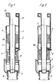
- FIG. 1 shows a drain fitting according to the invention in a not shown Cistern arranged, which is not filled with water.
- a first upper float 2 is fixed, which is mounted on a thread 5 and infinitely adjustable in height to adjust the General réellemenge.
- the Float 2 is in a space 4 within a float housing 20th arranged, with overflow pipe 1 and float 2 raised via a lift 17 can be.
- the overflow pipe 1 In the lower region of the overflow pipe 1 is designed as a seal 3 valve body provided that can open and close a sequence 8.
- a lower space 7 is provided in the a second float 6 loose between overflow pipe 1 and float housing 20 is arranged.
- the drain pipe 1 and the float 6 in the lowered position due to gravity, as the Swimmers 2 and 6 have no lift.
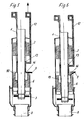
- FIG. 3 shows the introduction of a partial flush.
- This is the lifter 17 raised together with the overflow pipe 1 and the float 2, whereby in the lower part of the seal 3 is lifted off the drain 8. Thereby is both at the bottom of the seal 3 and on the top 3 of the same Pressure, so that due to the buoyant force of the float 2, the overflow tube 1 remains in the raised position until the water level is approximately on the Level 11 has dropped. Then the seal 3 is again at the outlet 8 and due to the water pressure this remains in the closed position and the cistern can be refilled.
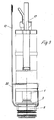
- FIG. 4 shows the initiation of a full flush. For this is at a pulled second lifter 12, wherein formed on the lift 12, a support edge 14 is, which is arranged below the lever 9 and then moves upwards is, whereby the lever 9 is pivoted upward and a further upward movement of the lifter 12 allows.
- the lower float 6 remains in the lower position, since it is held by a stop 90 and not further can be moved upwards.
- the lifter 12 is also in the upward movement attached to an annular collar 13, by means of which then the overflow pipe 1 and the upper float 2 are also moved upwards.
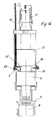
- the drain fitting is shown in a position during the full flush.
- the overflow pipe 1 is in the raised position and the valve body 3 is the Procedure 8 free. Due to the slowly sinking water level, the float loses 2 buoyancy and is pressed downwards due to gravity, wherein the collar 13 acts on the lifter 12, which in turn on the support edge 14 the lever 9 and thus presses on the lower float 6, the first for Buoyancy provides.
- FIGS. 8 to 14 show a second embodiment of a device according to the invention Shown drain fitting, wherein for functionally identical components the same reference numerals were used.
- the drain fitting is with the first lifter 12 and the second lifter 17 rotated by 90 °. Furthermore, the sealing element sits third on a flow 8.
- the drain fitting is shown in section, wherein the surrounding Cistern is filled with water.
- the float 6 is located on a stop 90th on, which is designed as a lever and also on the housing via a projection 22nd can be supported.
- the upper float 2 is fixed to the overflow pipe 1 and provides some buoyancy, but less than the water pressure on the sealing element 3.
- a lever 9 is provided, which is about an axis 21st is pivotally mounted on the float housing 20.
- a Stop 23 is formed so that the lever 9 is not over the horizontal position can be pivoted upwards.
- FIG. 12 shows the initiation of a full flush. This is the siphon 12 pulled so that the lifter 12 the float 2 together with the overflow pipe 1 moves upward, for which purpose on the lifter 12 a contact surface 24th is trained. By raising the overflow pipe 1, the sealing element 3 the sequence 8 free.
- a spring tab 25 which is connected to an annular Cuff 26 is formed.
- the spring tab 25 protrudes slightly obliquely radially, wherein in an upward movement of the lifter 12, the spring tab 25th is guided past the lever 9 and after exceeding the lever 9, the spring tab 25 protrudes outwards, so that when lowering the lifter 12th the spring tab 25 rests on the lifter 9. In this raised position is the Float 6 effective, which supports the lever 9 from below.
- the spring tab 25 is again within the float 6 arranged and the lever 9 may due to a stop on the Do not pivot float housing 20 down.
- the float takes off 6 and moves the Lever 9 back to the starting position, in which the lever 9 is arranged horizontally is and the stop 23 rests against the float housing 20.
- the individual components are made of plastic made using as a float foams or other suitable materials can be used.
- levers In the embodiments, only one lever is shown in each case, which is pivotable is hinged to the float housing. It is of course possible, two or more To arrange lever on the float housing. Likewise, several can Spring tabs 25 may be provided on the lifter 12.
Landscapes
- Health & Medical Sciences (AREA)
- Life Sciences & Earth Sciences (AREA)
- Engineering & Computer Science (AREA)
- Hydrology & Water Resources (AREA)
- Public Health (AREA)
- Water Supply & Treatment (AREA)
- Float Valves (AREA)
Abstract
Description
- Figuren 1 bis 7
- verschiedene Ansichten einer ersten Ausführungsform einer erfindungsgemäßen Ablaufarmatur in verschiedenen Positionen, und
- Figuren 8 bis 14
- verschiedene Ansichten eines zweiten Ausführungsbeispiels einer erfindungsgemäßen Ablaufarmatur in verschiedenen Positionen.
Claims (9)
- Ablaufarmatur für einen Spülkasten, mit einem Ventilkörper (3) zum Öffnen und Verschließen eines Ablaufes (8) für eine Teilspülung oder eine Vollspülung, mit einem in einem Schwimmergehäuse (20) an einem Überlaufrohr (1) gehaltenen ersten Schwimmer (2) und einem unter dem ersten Schwimmer (2) in dem Schwimmergehäuse (20) angeordneten zweiten Schwimmer (6), dessen Auftrieb begrenzt ist, dadurch gekennzeichnet, dass für eine Vollspülung mittels eines ersten Hebers (12) der erste obere Schwimmer (2), das Überlaufrohr (1) und Mittel zum Abstützen des ersten oberen Schwimmers (2) und des Überlaufrohres (1) in eine angehobene Position mit geöffnetem Ablauf (8) anhebbar sind.
- Ablaufarmatur nach Anspruch 1, dadurch gekennzeichnet, dass bei einer Vollspülung das Überlaufrohr (1) an einem Hebel (9) abgestützt ist, an dessen Unterseite der untere zweite Schwimmer (6) anlegbar ist.
- Ablaufarmatur nach Anspruch 1 oder 2, dadurch gekennzeichnet, dass bei gefülltem Spülkasten der Hebel (9) einen Anschlag für den unteren zweiten Schwimmer (6) ausbildet.
- Ablaufarmatur nach einem der Ansprüche 1 bis 3, dadurch gekennzeichnet, dass für eine Teilspülung mittels eines zweiten Hebers (17) der erste obere Schwimmer (2) und das Überlaufrohr (1) anhebbar sind.
- Ablaufarmatur nach einem der Ansprüche 1 bis 4, dadurch gekennzeichnet, dass die Mittel zum Abstützen des ersten oberen Schwimmers (2) und des Überlaufrohres (1) durch eine federnde Lasche gebildet sind, die auf den Hebel (9) auflegbar ist.
- Ablaufarmatur nach einem der Ansprüche 1 bis 4, dadurch gekennzeichnet, dass die Mittel zum Abstützen des ersten oberen Schwimmers (2) und des Überlaufrohres (1) durch eine Auflagekante (14) gebildet ist, mittels der der Hebel (9) nach oben verschwenkbar ist.
- Ablaufarmatur nach einem der Ansprüche 1 bis 6, dadurch gekennzeichnet, dass der zweite untere Schwimmer (6) lose zwischen Überlaufrohr (1) und Schwimmergehäuse (20) geführt ist.
- Ablaufarmatur nach einem der Ansprüche 1 bis 7, dadurch gekennzeichnet, dass der Hebel (9) am Schwimmergehäuse (20) drehbar gelagert ist.
- Ablaufarmatur nach einem der Ansprüche 1 bis 8, dadurch gekennzeichnet, dass an dem Schwimmergehäuse (20) ein Anschlag (90) ausgebildet ist.
Applications Claiming Priority (2)
| Application Number | Priority Date | Filing Date | Title |
|---|---|---|---|
| DE200420004528 DE202004004528U1 (de) | 2004-03-23 | 2004-03-23 | Ablaufarmatur für einen Spülkasten |
| DE202004004528U | 2004-03-23 |
Publications (3)
| Publication Number | Publication Date |
|---|---|
| EP1580338A2 true EP1580338A2 (de) | 2005-09-28 |
| EP1580338A3 EP1580338A3 (de) | 2006-08-02 |
| EP1580338B1 EP1580338B1 (de) | 2012-06-06 |
Family
ID=34854224
Family Applications (1)
| Application Number | Title | Priority Date | Filing Date |
|---|---|---|---|
| EP20050101269 Expired - Lifetime EP1580338B1 (de) | 2004-03-23 | 2005-02-18 | Ablaufarmatur für einen Spülkasten |
Country Status (4)
| Country | Link |
|---|---|
| EP (1) | EP1580338B1 (de) |
| DE (1) | DE202004004528U1 (de) |
| ES (1) | ES2386445T3 (de) |
| PT (1) | PT1580338E (de) |
Cited By (2)
| Publication number | Priority date | Publication date | Assignee | Title |
|---|---|---|---|---|
| ES2436649A1 (es) * | 2012-06-28 | 2014-01-03 | Roca Sanitario, S. A. | Dispositivo de carga y descarga para inodoros |
| EP3900530A1 (de) | 2020-04-23 | 2021-10-27 | Bayer AG | Flüssigkeitsmanagement für eine fangvorrichtung |
Families Citing this family (1)
| Publication number | Priority date | Publication date | Assignee | Title |
|---|---|---|---|---|
| CN105780888B (zh) * | 2016-05-09 | 2020-03-10 | 史国和 | 自动冲水阀电磁铁结构 |
Citations (1)
| Publication number | Priority date | Publication date | Assignee | Title |
|---|---|---|---|---|
| EP0727533A2 (de) | 1995-02-17 | 1996-08-21 | Wisa B.V. | Zweimengentoilettenspülvorrichtung |
Family Cites Families (5)
| Publication number | Priority date | Publication date | Assignee | Title |
|---|---|---|---|---|
| DE8436155U1 (de) * | 1984-12-11 | 1985-03-21 | Pag Presswerk Ag, 4300 Essen | Auslaufventil fuer wc-spuelkaesten |
| FR2678300B1 (fr) * | 1991-06-25 | 1993-10-01 | Lucien Tiret | Chasse d'eau a deux niveaux de remplissage. |
| DE19501355C2 (de) * | 1995-01-18 | 1997-07-10 | Friatec Keramik Kunststoff | Ablaufarmatur für einen Spülkasten |
| DE19730271C1 (de) * | 1997-07-15 | 1999-01-28 | Schwab Sanitaer Plastic Gmbh | Ablaufarmatur für einen Spülkasten |
| DE19736766C2 (de) * | 1997-08-23 | 2000-12-21 | Friatec Ag | Ablaufarmatur eines Spülkastens |
-
2004
- 2004-03-23 DE DE200420004528 patent/DE202004004528U1/de not_active Expired - Lifetime
-
2005
- 2005-02-18 ES ES05101269T patent/ES2386445T3/es not_active Expired - Lifetime
- 2005-02-18 EP EP20050101269 patent/EP1580338B1/de not_active Expired - Lifetime
- 2005-02-18 PT PT05101269T patent/PT1580338E/pt unknown
Patent Citations (1)
| Publication number | Priority date | Publication date | Assignee | Title |
|---|---|---|---|---|
| EP0727533A2 (de) | 1995-02-17 | 1996-08-21 | Wisa B.V. | Zweimengentoilettenspülvorrichtung |
Cited By (3)
| Publication number | Priority date | Publication date | Assignee | Title |
|---|---|---|---|---|
| ES2436649A1 (es) * | 2012-06-28 | 2014-01-03 | Roca Sanitario, S. A. | Dispositivo de carga y descarga para inodoros |
| EP3900530A1 (de) | 2020-04-23 | 2021-10-27 | Bayer AG | Flüssigkeitsmanagement für eine fangvorrichtung |
| WO2021213824A1 (de) | 2020-04-23 | 2021-10-28 | Bayer Aktiengesellschaft | Flüssigkeitsmanagement für eine fangvorrichtung |
Also Published As
| Publication number | Publication date |
|---|---|
| EP1580338A3 (de) | 2006-08-02 |
| ES2386445T3 (es) | 2012-08-21 |
| DE202004004528U1 (de) | 2005-08-18 |
| EP1580338B1 (de) | 2012-06-06 |
| PT1580338E (pt) | 2012-07-24 |
Similar Documents
| Publication | Publication Date | Title |
|---|---|---|
| EP0722020B1 (de) | Spüleinrichtung in einem WC-Spülkasten | |
| DE1904460A1 (de) | Spuelkastenfuellventil | |
| EP2865817A1 (de) | Ablaufgarnitur für einen Spülkasten | |
| EP2141294B1 (de) | Zwei-Mengen-Ablaufventil für einen Spülkasten mit verbessertem Steuerschwimmer-Mechanismus | |
| EP2092128B1 (de) | Zwei-mengen-ablaufventil | |
| EP1580338A2 (de) | Ablaufarmatur für einen Spülkasten | |
| EP1195475B1 (de) | Ablaufarmatur für einen WC-Spülkasten | |
| DE8436155U1 (de) | Auslaufventil fuer wc-spuelkaesten | |
| DE639760C (de) | Abtrittspuelkasten mit Ventilverschluss | |
| DE19730271C1 (de) | Ablaufarmatur für einen Spülkasten | |
| DE3140033A1 (de) | System zur funktionserweiterung konventioneller wc-spuelkaesten | |
| DE2611604C2 (de) | Vorrichtung zur Begrenzung des Wasserauslaufes aus Wasserbehältern mit einem Bodenauslauf | |
| DE2337853C2 (de) | Rückstau- und Geruchsverschluß für Flüssigkelten, Insbesondere Abwässer | |
| DE10132598A1 (de) | Vorrichtung zum Steuern des Auslassventils eines Toilettenspültanks | |
| DE3531165A1 (de) | Ablassventil fuer wc-spuelkaesten | |
| EP0962600A2 (de) | Ablaufgarnitur für einen Spülkasten | |
| DE69105268T2 (de) | Druckknopfspülmechanismus mit eintauchbarem Körper. | |
| DE2247282C3 (de) | Ablaufventil für einen Toilettenspülkasten | |
| DE29617195U1 (de) | Wassersparender Spülsteuermechanismus einer Toilette | |
| EP3219864A1 (de) | Entleerungsventile für einen flüssigkeitsbehälter, flüssigkeitsbehälter zum erzeugen eines spülschwalls und verfahren zum erzeugen eines spülschwalls | |
| DE68329C (de) | Spülvorrichtung mit Glockenheber für Aborte | |
| DE88838C (de) | ||
| DE2231237A1 (de) | Spuelkasten fuer wasserklosetts | |
| DE102024106329A1 (de) | Betätigungseinrichtung für ein Ablaufventil, Ablaufventil für einen Spülkasten und Spülkasten für eine Sanitäreinrichtung | |
| DE3214127A1 (de) | Spuelkasten fuer ein wc |
Legal Events
| Date | Code | Title | Description |
|---|---|---|---|
| PUAI | Public reference made under article 153(3) epc to a published international application that has entered the european phase |
Free format text: ORIGINAL CODE: 0009012 |
|
| AK | Designated contracting states |
Kind code of ref document: A2 Designated state(s): AT BE BG CH CY CZ DE DK EE ES FI FR GB GR HU IE IS IT LI LT LU MC NL PL PT RO SE SI SK TR |
|
| AX | Request for extension of the european patent |
Extension state: AL BA HR LV MK YU |
|
| PUAL | Search report despatched |
Free format text: ORIGINAL CODE: 0009013 |
|
| AK | Designated contracting states |
Kind code of ref document: A3 Designated state(s): AT BE BG CH CY CZ DE DK EE ES FI FR GB GR HU IE IS IT LI LT LU MC NL PL PT RO SE SI SK TR |
|
| AX | Request for extension of the european patent |
Extension state: AL BA HR LV MK YU |
|
| 17P | Request for examination filed |
Effective date: 20061228 |
|
| AKX | Designation fees paid |
Designated state(s): AT BE BG CH CY CZ DE DK EE ES FI FR GB GR HU IE IS IT LI LT LU MC NL PL PT RO SE SI SK TR |
|
| 17Q | First examination report despatched |
Effective date: 20080208 |
|
| GRAP | Despatch of communication of intention to grant a patent |
Free format text: ORIGINAL CODE: EPIDOSNIGR1 |
|
| GRAS | Grant fee paid |
Free format text: ORIGINAL CODE: EPIDOSNIGR3 |
|
| GRAA | (expected) grant |
Free format text: ORIGINAL CODE: 0009210 |
|
| AK | Designated contracting states |
Kind code of ref document: B1 Designated state(s): AT BE BG CH CY CZ DE DK EE ES FI FR GB GR HU IE IS IT LI LT LU MC NL PL PT RO SE SI SK TR |
|
| REG | Reference to a national code |
Ref country code: GB Ref legal event code: FG4D Free format text: NOT ENGLISH |
|
| REG | Reference to a national code |
Ref country code: DE Ref legal event code: R081 Ref document number: 502005012780 Country of ref document: DE Owner name: VIEGA TECHNOLOGY GMBH & CO. KG, DE Free format text: FORMER OWNER: VIEGA GMBH & CO. KG, 57439 ATTENDORN, DE |
|
| REG | Reference to a national code |
Ref country code: AT Ref legal event code: REF Ref document number: 561124 Country of ref document: AT Kind code of ref document: T Effective date: 20120615 Ref country code: CH Ref legal event code: EP |
|
| REG | Reference to a national code |
Ref country code: CH Ref legal event code: NV Representative=s name: TROESCH SCHEIDEGGER WERNER AG |
|
| REG | Reference to a national code |
Ref country code: IE Ref legal event code: FG4D Free format text: LANGUAGE OF EP DOCUMENT: GERMAN |
|
| REG | Reference to a national code |
Ref country code: PT Ref legal event code: SC4A Free format text: AVAILABILITY OF NATIONAL TRANSLATION Effective date: 20120718 |
|
| REG | Reference to a national code |
Ref country code: DE Ref legal event code: R096 Ref document number: 502005012780 Country of ref document: DE Effective date: 20120802 |
|
| REG | Reference to a national code |
Ref country code: ES Ref legal event code: FG2A Ref document number: 2386445 Country of ref document: ES Kind code of ref document: T3 Effective date: 20120821 |
|
| REG | Reference to a national code |
Ref country code: NL Ref legal event code: T3 |
|
| PG25 | Lapsed in a contracting state [announced via postgrant information from national office to epo] |
Ref country code: CY Free format text: LAPSE BECAUSE OF FAILURE TO SUBMIT A TRANSLATION OF THE DESCRIPTION OR TO PAY THE FEE WITHIN THE PRESCRIBED TIME-LIMIT Effective date: 20120606 Ref country code: FI Free format text: LAPSE BECAUSE OF FAILURE TO SUBMIT A TRANSLATION OF THE DESCRIPTION OR TO PAY THE FEE WITHIN THE PRESCRIBED TIME-LIMIT Effective date: 20120606 Ref country code: SE Free format text: LAPSE BECAUSE OF FAILURE TO SUBMIT A TRANSLATION OF THE DESCRIPTION OR TO PAY THE FEE WITHIN THE PRESCRIBED TIME-LIMIT Effective date: 20120606 Ref country code: LT Free format text: LAPSE BECAUSE OF FAILURE TO SUBMIT A TRANSLATION OF THE DESCRIPTION OR TO PAY THE FEE WITHIN THE PRESCRIBED TIME-LIMIT Effective date: 20120606 |
|
| REG | Reference to a national code |
Ref country code: LT Ref legal event code: MG4D Effective date: 20120606 |
|
| PG25 | Lapsed in a contracting state [announced via postgrant information from national office to epo] |
Ref country code: SI Free format text: LAPSE BECAUSE OF FAILURE TO SUBMIT A TRANSLATION OF THE DESCRIPTION OR TO PAY THE FEE WITHIN THE PRESCRIBED TIME-LIMIT Effective date: 20120606 Ref country code: GR Free format text: LAPSE BECAUSE OF FAILURE TO SUBMIT A TRANSLATION OF THE DESCRIPTION OR TO PAY THE FEE WITHIN THE PRESCRIBED TIME-LIMIT Effective date: 20120907 |
|
| PG25 | Lapsed in a contracting state [announced via postgrant information from national office to epo] |
Ref country code: SK Free format text: LAPSE BECAUSE OF FAILURE TO SUBMIT A TRANSLATION OF THE DESCRIPTION OR TO PAY THE FEE WITHIN THE PRESCRIBED TIME-LIMIT Effective date: 20120606 Ref country code: IS Free format text: LAPSE BECAUSE OF FAILURE TO SUBMIT A TRANSLATION OF THE DESCRIPTION OR TO PAY THE FEE WITHIN THE PRESCRIBED TIME-LIMIT Effective date: 20121006 Ref country code: EE Free format text: LAPSE BECAUSE OF FAILURE TO SUBMIT A TRANSLATION OF THE DESCRIPTION OR TO PAY THE FEE WITHIN THE PRESCRIBED TIME-LIMIT Effective date: 20120606 Ref country code: RO Free format text: LAPSE BECAUSE OF FAILURE TO SUBMIT A TRANSLATION OF THE DESCRIPTION OR TO PAY THE FEE WITHIN THE PRESCRIBED TIME-LIMIT Effective date: 20120606 Ref country code: CZ Free format text: LAPSE BECAUSE OF FAILURE TO SUBMIT A TRANSLATION OF THE DESCRIPTION OR TO PAY THE FEE WITHIN THE PRESCRIBED TIME-LIMIT Effective date: 20120606 |
|
| PG25 | Lapsed in a contracting state [announced via postgrant information from national office to epo] |
Ref country code: PL Free format text: LAPSE BECAUSE OF FAILURE TO SUBMIT A TRANSLATION OF THE DESCRIPTION OR TO PAY THE FEE WITHIN THE PRESCRIBED TIME-LIMIT Effective date: 20120606 |
|
| PLBE | No opposition filed within time limit |
Free format text: ORIGINAL CODE: 0009261 |
|
| STAA | Information on the status of an ep patent application or granted ep patent |
Free format text: STATUS: NO OPPOSITION FILED WITHIN TIME LIMIT |
|
| PG25 | Lapsed in a contracting state [announced via postgrant information from national office to epo] |
Ref country code: DK Free format text: LAPSE BECAUSE OF FAILURE TO SUBMIT A TRANSLATION OF THE DESCRIPTION OR TO PAY THE FEE WITHIN THE PRESCRIBED TIME-LIMIT Effective date: 20120606 |
|
| 26N | No opposition filed |
Effective date: 20130307 |
|
| REG | Reference to a national code |
Ref country code: DE Ref legal event code: R097 Ref document number: 502005012780 Country of ref document: DE Effective date: 20130307 |
|
| PG25 | Lapsed in a contracting state [announced via postgrant information from national office to epo] |
Ref country code: BG Free format text: LAPSE BECAUSE OF FAILURE TO SUBMIT A TRANSLATION OF THE DESCRIPTION OR TO PAY THE FEE WITHIN THE PRESCRIBED TIME-LIMIT Effective date: 20120906 |
|
| BERE | Be: lapsed |
Owner name: VIEGA G.M.B.H. & CO. KG Effective date: 20130228 |
|
| PG25 | Lapsed in a contracting state [announced via postgrant information from national office to epo] |
Ref country code: MC Free format text: LAPSE BECAUSE OF NON-PAYMENT OF DUE FEES Effective date: 20130228 |
|
| GBPC | Gb: european patent ceased through non-payment of renewal fee |
Effective date: 20130218 |
|
| REG | Reference to a national code |
Ref country code: IE Ref legal event code: MM4A |
|
| PG25 | Lapsed in a contracting state [announced via postgrant information from national office to epo] |
Ref country code: BE Free format text: LAPSE BECAUSE OF NON-PAYMENT OF DUE FEES Effective date: 20130228 Ref country code: GB Free format text: LAPSE BECAUSE OF NON-PAYMENT OF DUE FEES Effective date: 20130218 Ref country code: IE Free format text: LAPSE BECAUSE OF NON-PAYMENT OF DUE FEES Effective date: 20130218 |
|
| PG25 | Lapsed in a contracting state [announced via postgrant information from national office to epo] |
Ref country code: TR Free format text: LAPSE BECAUSE OF FAILURE TO SUBMIT A TRANSLATION OF THE DESCRIPTION OR TO PAY THE FEE WITHIN THE PRESCRIBED TIME-LIMIT Effective date: 20120606 |
|
| PG25 | Lapsed in a contracting state [announced via postgrant information from national office to epo] |
Ref country code: HU Free format text: LAPSE BECAUSE OF FAILURE TO SUBMIT A TRANSLATION OF THE DESCRIPTION OR TO PAY THE FEE WITHIN THE PRESCRIBED TIME-LIMIT; INVALID AB INITIO Effective date: 20050218 Ref country code: LU Free format text: LAPSE BECAUSE OF NON-PAYMENT OF DUE FEES Effective date: 20130218 |
|
| REG | Reference to a national code |
Ref country code: FR Ref legal event code: PLFP Year of fee payment: 12 |
|
| REG | Reference to a national code |
Ref country code: FR Ref legal event code: PLFP Year of fee payment: 13 |
|
| REG | Reference to a national code |
Ref country code: DE Ref legal event code: R082 Ref document number: 502005012780 Country of ref document: DE Representative=s name: COHAUSZ & FLORACK PATENT- UND RECHTSANWAELTE P, DE Ref country code: DE Ref legal event code: R081 Ref document number: 502005012780 Country of ref document: DE Owner name: VIEGA TECHNOLOGY GMBH & CO. KG, DE Free format text: FORMER OWNER: VIEGA GMBH & CO. KG, 57439 ATTENDORN, DE |
|
| REG | Reference to a national code |
Ref country code: AT Ref legal event code: PC Ref document number: 561124 Country of ref document: AT Kind code of ref document: T Owner name: VIEGA TECHNOLOGY GMBH & CO. KG, DE Effective date: 20170512 |
|
| REG | Reference to a national code |
Ref country code: NL Ref legal event code: PD Owner name: VIEGA TECHNOLOGY GMBH & CO. KG; DE Free format text: DETAILS ASSIGNMENT: CHANGE OF OWNER(S), ASSIGNMENT; FORMER OWNER NAME: VIEGA GMBH & CO. KG Effective date: 20170412 |
|
| REG | Reference to a national code |
Ref country code: FR Ref legal event code: TP Owner name: VIEGA TECHNOLOGY GMBH & CO. KG, DE Effective date: 20171013 |
|
| REG | Reference to a national code |
Ref country code: ES Ref legal event code: PC2A Owner name: VIEGA TECHNOLOGY GMBH & CO. KG Effective date: 20180108 |
|
| REG | Reference to a national code |
Ref country code: FR Ref legal event code: PLFP Year of fee payment: 14 |
|
| REG | Reference to a national code |
Ref country code: CH Ref legal event code: PUE Owner name: VIEGA TECHNOLOGY GMBH AND CO. KG, DE Free format text: FORMER OWNER: VIEGA GMBH AND CO. KG, DE |
|
| PGFP | Annual fee paid to national office [announced via postgrant information from national office to epo] |
Ref country code: NL Payment date: 20210217 Year of fee payment: 17 Ref country code: FR Payment date: 20210217 Year of fee payment: 17 Ref country code: IT Payment date: 20210219 Year of fee payment: 17 |
|
| PGFP | Annual fee paid to national office [announced via postgrant information from national office to epo] |
Ref country code: ES Payment date: 20210319 Year of fee payment: 17 |
|
| PGFP | Annual fee paid to national office [announced via postgrant information from national office to epo] |
Ref country code: CH Payment date: 20220222 Year of fee payment: 18 Ref country code: AT Payment date: 20220223 Year of fee payment: 18 |
|
| PGFP | Annual fee paid to national office [announced via postgrant information from national office to epo] |
Ref country code: PT Payment date: 20220125 Year of fee payment: 18 |
|
| REG | Reference to a national code |
Ref country code: NL Ref legal event code: MM Effective date: 20220301 |
|
| PG25 | Lapsed in a contracting state [announced via postgrant information from national office to epo] |
Ref country code: NL Free format text: LAPSE BECAUSE OF NON-PAYMENT OF DUE FEES Effective date: 20220301 Ref country code: FR Free format text: LAPSE BECAUSE OF NON-PAYMENT OF DUE FEES Effective date: 20220228 |
|
| REG | Reference to a national code |
Ref country code: ES Ref legal event code: FD2A Effective date: 20230331 |
|
| PG25 | Lapsed in a contracting state [announced via postgrant information from national office to epo] |
Ref country code: ES Free format text: LAPSE BECAUSE OF NON-PAYMENT OF DUE FEES Effective date: 20220219 |
|
| PG25 | Lapsed in a contracting state [announced via postgrant information from national office to epo] |
Ref country code: IT Free format text: LAPSE BECAUSE OF NON-PAYMENT OF DUE FEES Effective date: 20220218 |
|
| PGFP | Annual fee paid to national office [announced via postgrant information from national office to epo] |
Ref country code: DE Payment date: 20230223 Year of fee payment: 19 |
|
| REG | Reference to a national code |
Ref country code: CH Ref legal event code: PL |
|
| REG | Reference to a national code |
Ref country code: AT Ref legal event code: MM01 Ref document number: 561124 Country of ref document: AT Kind code of ref document: T Effective date: 20230218 |
|
| PG25 | Lapsed in a contracting state [announced via postgrant information from national office to epo] |
Ref country code: PT Free format text: LAPSE BECAUSE OF NON-PAYMENT OF DUE FEES Effective date: 20230818 Ref country code: LI Free format text: LAPSE BECAUSE OF NON-PAYMENT OF DUE FEES Effective date: 20230228 Ref country code: CH Free format text: LAPSE BECAUSE OF NON-PAYMENT OF DUE FEES Effective date: 20230228 Ref country code: AT Free format text: LAPSE BECAUSE OF NON-PAYMENT OF DUE FEES Effective date: 20230218 |
|
| REG | Reference to a national code |
Ref country code: DE Ref legal event code: R119 Ref document number: 502005012780 Country of ref document: DE |
|
| PG25 | Lapsed in a contracting state [announced via postgrant information from national office to epo] |
Ref country code: DE Free format text: LAPSE BECAUSE OF NON-PAYMENT OF DUE FEES Effective date: 20240903 |
|
| PG25 | Lapsed in a contracting state [announced via postgrant information from national office to epo] |
Ref country code: DE Free format text: LAPSE BECAUSE OF NON-PAYMENT OF DUE FEES Effective date: 20240903 |