EP1579471B1 - Cathode pour pulverisation sous vide - Google Patents
Cathode pour pulverisation sous vide Download PDFInfo
- Publication number
- EP1579471B1 EP1579471B1 EP03755581A EP03755581A EP1579471B1 EP 1579471 B1 EP1579471 B1 EP 1579471B1 EP 03755581 A EP03755581 A EP 03755581A EP 03755581 A EP03755581 A EP 03755581A EP 1579471 B1 EP1579471 B1 EP 1579471B1
- Authority
- EP
- European Patent Office
- Prior art keywords
- membrane
- frame
- vacuum sputtering
- base
- cathode
- Prior art date
- Legal status (The legal status is an assumption and is not a legal conclusion. Google has not performed a legal analysis and makes no representation as to the accuracy of the status listed.)
- Expired - Lifetime
Links
Images
Classifications
-
- H—ELECTRICITY
- H01—ELECTRIC ELEMENTS
- H01J—ELECTRIC DISCHARGE TUBES OR DISCHARGE LAMPS
- H01J37/00—Discharge tubes with provision for introducing objects or material to be exposed to the discharge, e.g. for the purpose of examination or processing thereof
- H01J37/32—Gas-filled discharge tubes
- H01J37/34—Gas-filled discharge tubes operating with cathodic sputtering
- H01J37/3411—Constructional aspects of the reactor
- H01J37/3435—Target holders (includes backing plates and endblocks)
-
- H—ELECTRICITY
- H01—ELECTRIC ELEMENTS
- H01J—ELECTRIC DISCHARGE TUBES OR DISCHARGE LAMPS
- H01J37/00—Discharge tubes with provision for introducing objects or material to be exposed to the discharge, e.g. for the purpose of examination or processing thereof
- H01J37/32—Gas-filled discharge tubes
- H01J37/34—Gas-filled discharge tubes operating with cathodic sputtering
- H01J37/3488—Constructional details of particle beam apparatus not otherwise provided for, e.g. arrangement, mounting, housing, environment; special provisions for cleaning or maintenance of the apparatus
- H01J37/3497—Temperature of target
Definitions
- the invention relates to the technical field of sputtering materials, especially in a vacuum treatment plant, and more particularly cathodes for the production of steam.
- a membrane cathode is in the form of a base having, in its thickness, cavities constituting channels for the circulation of a cooling fluid on this base is fixed, generally by means of screws, a membrane. Opposite this membrane support base, is mounted in a contiguous manner, a target for spraying a material. Generally, the membrane is made by means of a single material.
- the membrane is composed of at least two superimposed materials.
- the cathode according to the invention is composed of a support base (3) having any type of arrangement for the circulation of a cooling fluid with an inlet (E) and an outlet (S).
- the base (3) for example of generally parallelepipedal shape, receives, in superposition, a plate (11) suitably cut to form a frame delimiting at least one empty space (11a) for the circulation of the cooling fluid.
- At least one of the sides of the frame (11) has, in the same plane, at least one arm (11b) for delimiting circulation channels of the cooling fluid.
- This frame (11) receives, in superposition, a membrane (4).
- the base (3), the frame (11) and the membrane (4) are assembled together at their periphery. For example, this connection is made by means of a through solder (ST).
- the membrane (4) is composed of at least two layers (4a) and (4b) of different materials.
- the layer (4b), arranged on the side of the frame (11) which acts as a structure, is made of a material selected to accept an elastic deformation.
- the other layer (4a) is made of a selected material to accept plastic deformation, in order to conform to the surface of a sputtering target (2) (dashed lines, figure 3 ).
- the invention finds an advantageous application in the field of vacuum cathode sputtering by means of a target.
Landscapes
- Physics & Mathematics (AREA)
- Engineering & Computer Science (AREA)
- Plasma & Fusion (AREA)
- Chemical & Material Sciences (AREA)
- Analytical Chemistry (AREA)
- Physical Vapour Deposition (AREA)
- Cold Cathode And The Manufacture (AREA)
- Coating By Spraying Or Casting (AREA)
Description
- L'invention se rattache au secteur technique de la pulvérisation cathodique de matériaux, notamment dans une installation de traitement sous vide, et plus particulièrement des cathodes destinées à la production de vapeur.
- Généralement, selon l'état antérieur de la technique, une cathode à membrane se présente sous forme d'une embase présentant, dans son épaisseur, des cavités constituant des canaux pour la circulation d'un fluide de refroidissement Sur cette embase est fixée, généralement au moyen de vis, une membrane. En regard de cette embase support à membrane, est montée, d'une manière jointive, une cible pour la pulvérisation d'un matériau. Généralement, la membrane est réalisée au moyen d'un seul matériau.
- Cet état de le technique peut être illustré par l'enseigement des documents
CH 672319 US 5071535 . - Pour resoudre ce pb il a été conçu une methode conforme aux caracteristiques de la revendication 1
- Avantageusement, la membrane est composée d'au moins deux matériaux superposés.
- L'invention est exposée ci-après plus en détail à l'aide des figures des dessins annexés dans lesquels :
- la
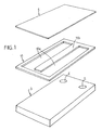
figure 1 est une vue en perspective, avant montage, des principaux éléments de la cathode, selon l'invention ; - la
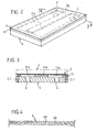
figure 2 est une vue en perspective correspondant à lafigure 1 , après assemblage des différents éléments ; - la
figure 3 est une vue en coupe transversale considérée selon la ligne 3-3 de lafigure 2 ; - la
figure 4 est une vue partielle, à très grande échelle, montrant la structure interne de la membrane en tant que telle ; - Comme le montre la
figure 1 , la cathode, selon l'invention, est composée d'une embase support (3) présentant tout type d'agencement pour la circulation d'un fluide de refroidissement avec une entrée (E) et une sortie (S). L'embase (3), par exemple de forme générale parallélépipédique, reçoit, en superposition, une plaque (11) convenablement découpée pour constituer un cadre délimitant au moins un espace vide (11a) pour la circulation du fluide de refroidissement. - L'un des côtés au moins du cadre (11) présente, dans le même plan, au moins un bras (11b) pour délimiter des canaux de circulation du fluide de refroidissement.
- Ce cadre (11) reçoit, en superposition, une membrane (4). L'embase (3), le cadre (11) et la membrane (4) sont assemblés ensemble, au niveau de leur périphérie. Par exemple, cette liaison s'effectue au moyen d'une soudure traversante (ST).
- Selon une autre caractéristique, la membrane (4) est composée d'au moins deux couches (4a) et (4b) de matériaux différents. La couche (4b), disposée du côté du cadre (11) qui fait office de structure, est réalisée dans un matériau sélectionné pour accepter une déformation élastique. L'autre couche (4a) est réalisée dans un matériau sélectionné pour accepter une déformation plastique, afin d'épouser la surface d'une cible de pulvérisation (2) (tracé traits interrompus,
figure 3 ). - Ainsi, l'invention trouve une application avantageuse dans le domaine de la pulvérisation cathodique sous vide au moyen d'une cible.
- Les avantages ressortent bien de la description.
Claims (2)
- Cathode pour pulvérisation sous vide dont le support de cible (2) est constitué par un refroidisseur, caractérisée en ce qu'elle comprend une embase support (3) sur laquelle est superposé un cadre (11) qui présente, dans le même plan, au moins un bras (11b) pour délimiter des canaux de circulation (11a) d'un fluide de refroidissement.
ledit cadre (11) recevant en superposition une membrane (4), l'embase (3), le cadre (11) et la membrane (4) étant assemblés ensemble en périphérie. - Cathode selon la revendication 1, caractérisée en ce que la membrane (4) est composée d'au moins deux matériaux superposés (4a) et (4b).
Priority Applications (1)
| Application Number | Priority Date | Filing Date | Title |
|---|---|---|---|
| SI200332064T SI1579471T1 (sl) | 2002-07-10 | 2003-07-08 | Katoda za vakuumsko razprševanje |
Applications Claiming Priority (3)
| Application Number | Priority Date | Filing Date | Title |
|---|---|---|---|
| FR0208869 | 2002-07-10 | ||
| FR0208869A FR2842348B1 (fr) | 2002-07-10 | 2002-07-10 | Cathode pour pulverisation sous vide |
| PCT/FR2003/002111 WO2004008479A2 (fr) | 2002-07-10 | 2003-07-08 | Cathode pour pulverisation sous vide |
Publications (2)
| Publication Number | Publication Date |
|---|---|
| EP1579471A2 EP1579471A2 (fr) | 2005-09-28 |
| EP1579471B1 true EP1579471B1 (fr) | 2011-10-12 |
Family
ID=29763836
Family Applications (1)
| Application Number | Title | Priority Date | Filing Date |
|---|---|---|---|
| EP03755581A Expired - Lifetime EP1579471B1 (fr) | 2002-07-10 | 2003-07-08 | Cathode pour pulverisation sous vide |
Country Status (14)
| Country | Link |
|---|---|
| US (1) | US7632383B2 (fr) |
| EP (1) | EP1579471B1 (fr) |
| JP (1) | JP5079212B2 (fr) |
| CN (1) | CN100578724C (fr) |
| AT (1) | ATE528785T1 (fr) |
| AU (1) | AU2003273424A1 (fr) |
| CA (1) | CA2492174C (fr) |
| ES (1) | ES2371246T3 (fr) |
| FR (1) | FR2842348B1 (fr) |
| MX (1) | MXPA05000457A (fr) |
| PL (1) | PL207112B1 (fr) |
| SI (1) | SI1579471T1 (fr) |
| TW (1) | TWI325446B (fr) |
| WO (1) | WO2004008479A2 (fr) |
Families Citing this family (3)
| Publication number | Priority date | Publication date | Assignee | Title |
|---|---|---|---|---|
| DE102012006717A1 (de) * | 2012-04-04 | 2013-10-10 | Oerlikon Trading Ag, Trübbach | An eine indirekte Kühlvorrichtung angepasstes Target |
| SE542687C2 (en) | 2018-06-27 | 2020-06-23 | Impact Coatings Ab Publ | Arc source system for a cathode |
| CN116887501A (zh) * | 2023-07-14 | 2023-10-13 | 中国电子科技集团公司第十二研究所 | 一种电子直线加速器 |
Family Cites Families (15)
| Publication number | Priority date | Publication date | Assignee | Title |
|---|---|---|---|---|
| US4437966A (en) * | 1982-09-30 | 1984-03-20 | Gte Products Corporation | Sputtering cathode apparatus |
| JP2731152B2 (ja) * | 1987-11-17 | 1998-03-25 | 日立金属株式会社 | 冷却部材付きスパッタリング用ターゲット |
| CH672319A5 (en) * | 1987-12-20 | 1989-11-15 | Bogdan Zega | Sputtering target cooling system - has metal membrane sepg. cooling liq. circuit from sputtering chamber |
| JPH02205669A (ja) * | 1989-02-03 | 1990-08-15 | Matsushita Electric Ind Co Ltd | スパッタ装置 |
| JPH02258974A (ja) * | 1989-03-30 | 1990-10-19 | Sumitomo Metal Ind Ltd | スパッタリング装置のターゲット及び陰極部 |
| DE4015388C2 (de) * | 1990-05-14 | 1997-07-17 | Leybold Ag | Kathodenzerstäubungsvorrichtung |
| EP0512456B1 (fr) * | 1991-05-08 | 1997-06-18 | Balzers Aktiengesellschaft | Procédé de montage et démontage d'une plaque cible dans une chambre de traitement sous vide, dispositif de montage, plaque cible et chambre à vide |
| US5147521A (en) * | 1991-05-20 | 1992-09-15 | Tosoh Smd, Inc. | Quick change sputter target assembly |
| JPH0525620A (ja) * | 1991-07-18 | 1993-02-02 | Hitachi Ltd | スパツタリングターゲツト |
| DE4301516C2 (de) * | 1993-01-21 | 2003-02-13 | Applied Films Gmbh & Co Kg | Targetkühlung mit Wanne |
| US5529673A (en) * | 1995-02-17 | 1996-06-25 | Sony Corporation | Mechanically joined sputtering target and adapter therefor |
| JPH08246144A (ja) * | 1995-03-10 | 1996-09-24 | Japan Energy Corp | スパッタリングターゲット用バッキングプレート組立部品 |
| DE29512094U1 (de) * | 1995-07-27 | 1996-02-01 | Heron Sondermaschinen Und Steuerungen Ges.M.B.H., Lustenau | Klemmvorrichtung für Schutzeinrichtungen an Maschinen u.dgl. |
| US5863397A (en) * | 1997-07-11 | 1999-01-26 | Taiwan Semiconductor Manufacturing Co Ltd. | Target mounting apparatus for vapor deposition system |
| JP4130263B2 (ja) * | 1998-12-03 | 2008-08-06 | 三菱伸銅株式会社 | スパッタリング装置および水冷カソード |
-
2002
- 2002-07-10 FR FR0208869A patent/FR2842348B1/fr not_active Expired - Fee Related
-
2003
- 2003-07-08 SI SI200332064T patent/SI1579471T1/sl unknown
- 2003-07-08 AT AT03755581T patent/ATE528785T1/de not_active IP Right Cessation
- 2003-07-08 WO PCT/FR2003/002111 patent/WO2004008479A2/fr not_active Ceased
- 2003-07-08 EP EP03755581A patent/EP1579471B1/fr not_active Expired - Lifetime
- 2003-07-08 CN CN03819917A patent/CN100578724C/zh not_active Expired - Lifetime
- 2003-07-08 JP JP2004520735A patent/JP5079212B2/ja not_active Expired - Lifetime
- 2003-07-08 MX MXPA05000457A patent/MXPA05000457A/es active IP Right Grant
- 2003-07-08 TW TW092118631A patent/TWI325446B/zh not_active IP Right Cessation
- 2003-07-08 CA CA2492174A patent/CA2492174C/fr not_active Expired - Lifetime
- 2003-07-08 ES ES03755581T patent/ES2371246T3/es not_active Expired - Lifetime
- 2003-07-08 PL PL377089A patent/PL207112B1/pl unknown
- 2003-07-08 AU AU2003273424A patent/AU2003273424A1/en not_active Abandoned
-
2005
- 2005-01-10 US US11/032,430 patent/US7632383B2/en not_active Expired - Lifetime
Also Published As
| Publication number | Publication date |
|---|---|
| CN1757091A (zh) | 2006-04-05 |
| WO2004008479A2 (fr) | 2004-01-22 |
| FR2842348A1 (fr) | 2004-01-16 |
| FR2842348B1 (fr) | 2004-09-10 |
| EP1579471A2 (fr) | 2005-09-28 |
| US20050155855A1 (en) | 2005-07-21 |
| CA2492174A1 (fr) | 2004-01-22 |
| JP2006512479A (ja) | 2006-04-13 |
| PL207112B1 (pl) | 2010-11-30 |
| TW200401837A (en) | 2004-02-01 |
| ATE528785T1 (de) | 2011-10-15 |
| MXPA05000457A (es) | 2005-07-22 |
| PL377089A1 (pl) | 2006-01-23 |
| WO2004008479A3 (fr) | 2005-12-15 |
| CN100578724C (zh) | 2010-01-06 |
| JP5079212B2 (ja) | 2012-11-21 |
| TWI325446B (en) | 2010-06-01 |
| SI1579471T1 (sl) | 2011-12-30 |
| AU2003273424A1 (en) | 2004-02-02 |
| CA2492174C (fr) | 2014-04-15 |
| US7632383B2 (en) | 2009-12-15 |
| ES2371246T3 (es) | 2011-12-28 |
Similar Documents
| Publication | Publication Date | Title |
|---|---|---|
| US11306973B2 (en) | Liquid cooling heat exchanger and method for making the same | |
| US11022379B2 (en) | CTE-matched heat pipe | |
| EP3220729B1 (fr) | Dispositif electronique et methode d assemblage d'un tel dispositif | |
| EP1243169B1 (fr) | Module electronique a haut pouvoir de refroidissement | |
| EP1595284A1 (fr) | Semelle de collage electrostatique avec electrode radiofrequence et moyens thermostatiques integres | |
| FR3074011A1 (fr) | Module electrique de puissance | |
| FR2752927A1 (fr) | Echangeur de chaleur ayant la structure d'une pile de plaques et procede pour sa fabrication | |
| CN102851643A (zh) | 非粘合溅射结构以及形成用于溅射的结构的方法 | |
| FR2804767A1 (fr) | Structure de dissipateur thermique pour utilisation dans un ordinateur | |
| JP2022548244A (ja) | セラミックヒータおよび液相拡散接合を用いた形成方法 | |
| CA1218739A (fr) | Support allege pour composants electroniques | |
| FR2770632A1 (fr) | Echangeur de chaleur a collecteur renforce, notamment pour vehicule automobile | |
| FR2468772A1 (fr) | Rotor composite pour pompe centrifuge destinee a refouler des suspensions abrasives | |
| CA2809401C (fr) | Circuit imprime comportant au moins un composant ceramique | |
| FR2943849A1 (fr) | Procede de realisation de boitiers semi-conducteurs et boitier semi-conducteur | |
| EP1239515B1 (fr) | Substrat pour circuit électronique de puissance et module électronique de puissance utilisant un tel substrat | |
| WO2021234244A1 (fr) | Structure d'assemblage d'une pièce comprenant une première partie métallique et une deuxième partie en matériau composite à matrice organique | |
| EP4082306B1 (fr) | Dispositif de dissipation de chaleur, système électrique comportant un tel dispositif et procédé de fabrication associé | |
| CA2492174C (fr) | Cathode pour pulverisation sous vide | |
| FR3071354A1 (fr) | Dispositif electronique comprenant un substrat de support et un capot d'encapsulation d'un composant electronique | |
| JP2013012663A (ja) | 放熱部品及び半導体モジュール装置 | |
| FR2977975A1 (fr) | Boitier electronique a via thermique et procede de fabrication | |
| FR2927762A1 (fr) | Ensemble de commutation pour un systeme d'allumage d'avion | |
| FR2742000A1 (fr) | Composant semiconducteur a montage par brasure | |
| FR2796497A1 (fr) | Interconnexion perfectionnee entre un composant electronique et une carte |
Legal Events
| Date | Code | Title | Description |
|---|---|---|---|
| PUAI | Public reference made under article 153(3) epc to a published international application that has entered the european phase |
Free format text: ORIGINAL CODE: 0009012 |
|
| 17P | Request for examination filed |
Effective date: 20050110 |
|
| AK | Designated contracting states |
Kind code of ref document: A2 Designated state(s): AT BE BG CH CY CZ DE DK EE ES FI FR GB GR HU IE IT LI LU MC NL PT RO SE SI SK TR |
|
| AX | Request for extension of the european patent |
Extension state: AL LT LV MK |
|
| DAX | Request for extension of the european patent (deleted) | ||
| PUAK | Availability of information related to the publication of the international search report |
Free format text: ORIGINAL CODE: 0009015 |
|
| 17Q | First examination report despatched |
Effective date: 20090511 |
|
| GRAJ | Information related to disapproval of communication of intention to grant by the applicant or resumption of examination proceedings by the epo deleted |
Free format text: ORIGINAL CODE: EPIDOSDIGR1 |
|
| GRAP | Despatch of communication of intention to grant a patent |
Free format text: ORIGINAL CODE: EPIDOSNIGR1 |
|
| GRAP | Despatch of communication of intention to grant a patent |
Free format text: ORIGINAL CODE: EPIDOSNIGR1 |
|
| GRAS | Grant fee paid |
Free format text: ORIGINAL CODE: EPIDOSNIGR3 |
|
| RAP1 | Party data changed (applicant data changed or rights of an application transferred) |
Owner name: H.E.F. |
|
| GRAA | (expected) grant |
Free format text: ORIGINAL CODE: 0009210 |
|
| AK | Designated contracting states |
Kind code of ref document: B1 Designated state(s): AT BE BG CH CY CZ DE DK EE ES FI FR GB GR HU IE IT LI LU MC NL PT RO SE SI SK TR |
|
| REG | Reference to a national code |
Ref country code: GB Ref legal event code: FG4D Free format text: NOT ENGLISH |
|
| REG | Reference to a national code |
Ref country code: CH Ref legal event code: EP |
|
| REG | Reference to a national code |
Ref country code: IE Ref legal event code: FG4D |
|
| REG | Reference to a national code |
Ref country code: DE Ref legal event code: R081 Ref document number: 60338751 Country of ref document: DE Owner name: H.E.F., FR Free format text: FORMER OWNER: TECMACHINE, ANDREZIEUX-BOUTHEON, FR |
|
| REG | Reference to a national code |
Ref country code: ES Ref legal event code: FG2A Ref document number: 2371246 Country of ref document: ES Kind code of ref document: T3 Effective date: 20111228 |
|
| REG | Reference to a national code |
Ref country code: DE Ref legal event code: R096 Ref document number: 60338751 Country of ref document: DE Effective date: 20120112 |
|
| REG | Reference to a national code |
Ref country code: NL Ref legal event code: VDEP Effective date: 20111012 |
|
| REG | Reference to a national code |
Ref country code: SK Ref legal event code: T3 Ref document number: E 10480 Country of ref document: SK |
|
| REG | Reference to a national code |
Ref country code: AT Ref legal event code: MK05 Ref document number: 528785 Country of ref document: AT Kind code of ref document: T Effective date: 20111012 |
|
| PG25 | Lapsed in a contracting state [announced via postgrant information from national office to epo] |
Ref country code: GR Free format text: LAPSE BECAUSE OF FAILURE TO SUBMIT A TRANSLATION OF THE DESCRIPTION OR TO PAY THE FEE WITHIN THE PRESCRIBED TIME-LIMIT Effective date: 20120113 Ref country code: SE Free format text: LAPSE BECAUSE OF FAILURE TO SUBMIT A TRANSLATION OF THE DESCRIPTION OR TO PAY THE FEE WITHIN THE PRESCRIBED TIME-LIMIT Effective date: 20111012 Ref country code: PT Free format text: LAPSE BECAUSE OF FAILURE TO SUBMIT A TRANSLATION OF THE DESCRIPTION OR TO PAY THE FEE WITHIN THE PRESCRIBED TIME-LIMIT Effective date: 20120213 Ref country code: NL Free format text: LAPSE BECAUSE OF FAILURE TO SUBMIT A TRANSLATION OF THE DESCRIPTION OR TO PAY THE FEE WITHIN THE PRESCRIBED TIME-LIMIT Effective date: 20111012 |
|
| REG | Reference to a national code |
Ref country code: HU Ref legal event code: AG4A Ref document number: E012883 Country of ref document: HU |
|
| PG25 | Lapsed in a contracting state [announced via postgrant information from national office to epo] |
Ref country code: CY Free format text: LAPSE BECAUSE OF FAILURE TO SUBMIT A TRANSLATION OF THE DESCRIPTION OR TO PAY THE FEE WITHIN THE PRESCRIBED TIME-LIMIT Effective date: 20111012 |
|
| PG25 | Lapsed in a contracting state [announced via postgrant information from national office to epo] |
Ref country code: BG Free format text: LAPSE BECAUSE OF FAILURE TO SUBMIT A TRANSLATION OF THE DESCRIPTION OR TO PAY THE FEE WITHIN THE PRESCRIBED TIME-LIMIT Effective date: 20120112 Ref country code: DK Free format text: LAPSE BECAUSE OF FAILURE TO SUBMIT A TRANSLATION OF THE DESCRIPTION OR TO PAY THE FEE WITHIN THE PRESCRIBED TIME-LIMIT Effective date: 20111012 Ref country code: EE Free format text: LAPSE BECAUSE OF FAILURE TO SUBMIT A TRANSLATION OF THE DESCRIPTION OR TO PAY THE FEE WITHIN THE PRESCRIBED TIME-LIMIT Effective date: 20111012 |
|
| PLBE | No opposition filed within time limit |
Free format text: ORIGINAL CODE: 0009261 |
|
| STAA | Information on the status of an ep patent application or granted ep patent |
Free format text: STATUS: NO OPPOSITION FILED WITHIN TIME LIMIT |
|
| PG25 | Lapsed in a contracting state [announced via postgrant information from national office to epo] |
Ref country code: IT Free format text: LAPSE BECAUSE OF FAILURE TO SUBMIT A TRANSLATION OF THE DESCRIPTION OR TO PAY THE FEE WITHIN THE PRESCRIBED TIME-LIMIT Effective date: 20111012 Ref country code: RO Free format text: LAPSE BECAUSE OF FAILURE TO SUBMIT A TRANSLATION OF THE DESCRIPTION OR TO PAY THE FEE WITHIN THE PRESCRIBED TIME-LIMIT Effective date: 20111012 |
|
| 26N | No opposition filed |
Effective date: 20120713 |
|
| REG | Reference to a national code |
Ref country code: DE Ref legal event code: R097 Ref document number: 60338751 Country of ref document: DE Effective date: 20120713 |
|
| PG25 | Lapsed in a contracting state [announced via postgrant information from national office to epo] |
Ref country code: AT Free format text: LAPSE BECAUSE OF FAILURE TO SUBMIT A TRANSLATION OF THE DESCRIPTION OR TO PAY THE FEE WITHIN THE PRESCRIBED TIME-LIMIT Effective date: 20111012 |
|
| PG25 | Lapsed in a contracting state [announced via postgrant information from national office to epo] |
Ref country code: MC Free format text: LAPSE BECAUSE OF NON-PAYMENT OF DUE FEES Effective date: 20120731 |
|
| PG25 | Lapsed in a contracting state [announced via postgrant information from national office to epo] |
Ref country code: FI Free format text: LAPSE BECAUSE OF FAILURE TO SUBMIT A TRANSLATION OF THE DESCRIPTION OR TO PAY THE FEE WITHIN THE PRESCRIBED TIME-LIMIT Effective date: 20111012 |
|
| PG25 | Lapsed in a contracting state [announced via postgrant information from national office to epo] |
Ref country code: TR Free format text: LAPSE BECAUSE OF FAILURE TO SUBMIT A TRANSLATION OF THE DESCRIPTION OR TO PAY THE FEE WITHIN THE PRESCRIBED TIME-LIMIT Effective date: 20111012 |
|
| REG | Reference to a national code |
Ref country code: FR Ref legal event code: PLFP Year of fee payment: 14 |
|
| REG | Reference to a national code |
Ref country code: FR Ref legal event code: PLFP Year of fee payment: 15 |
|
| REG | Reference to a national code |
Ref country code: FR Ref legal event code: PLFP Year of fee payment: 16 |
|
| PGFP | Annual fee paid to national office [announced via postgrant information from national office to epo] |
Ref country code: SK Payment date: 20220608 Year of fee payment: 20 Ref country code: GB Payment date: 20220608 Year of fee payment: 20 Ref country code: CZ Payment date: 20220607 Year of fee payment: 20 |
|
| PGFP | Annual fee paid to national office [announced via postgrant information from national office to epo] |
Ref country code: BE Payment date: 20220603 Year of fee payment: 20 |
|
| PGFP | Annual fee paid to national office [announced via postgrant information from national office to epo] |
Ref country code: LU Payment date: 20220726 Year of fee payment: 20 Ref country code: IE Payment date: 20220727 Year of fee payment: 20 Ref country code: ES Payment date: 20220803 Year of fee payment: 20 Ref country code: DE Payment date: 20220909 Year of fee payment: 20 |
|
| PGFP | Annual fee paid to national office [announced via postgrant information from national office to epo] |
Ref country code: SI Payment date: 20220603 Year of fee payment: 20 Ref country code: HU Payment date: 20220608 Year of fee payment: 20 Ref country code: FR Payment date: 20220729 Year of fee payment: 20 |
|
| PGFP | Annual fee paid to national office [announced via postgrant information from national office to epo] |
Ref country code: CH Payment date: 20220802 Year of fee payment: 20 |
|
| REG | Reference to a national code |
Ref country code: DE Ref legal event code: R071 Ref document number: 60338751 Country of ref document: DE |
|
| REG | Reference to a national code |
Ref country code: CH Ref legal event code: PL |
|
| REG | Reference to a national code |
Ref country code: SK Ref legal event code: MK4A Ref document number: E 10480 Country of ref document: SK Expiry date: 20230708 Ref country code: ES Ref legal event code: FD2A Effective date: 20230726 |
|
| REG | Reference to a national code |
Ref country code: BE Ref legal event code: MK Effective date: 20230708 |
|
| PG25 | Lapsed in a contracting state [announced via postgrant information from national office to epo] |
Ref country code: CZ Free format text: LAPSE BECAUSE OF EXPIRATION OF PROTECTION Effective date: 20230708 |
|
| REG | Reference to a national code |
Ref country code: GB Ref legal event code: PE20 Expiry date: 20230707 |
|
| REG | Reference to a national code |
Ref country code: IE Ref legal event code: MK9A |
|
| PG25 | Lapsed in a contracting state [announced via postgrant information from national office to epo] |
Ref country code: SI Free format text: LAPSE BECAUSE OF EXPIRATION OF PROTECTION Effective date: 20230709 |
|
| PG25 | Lapsed in a contracting state [announced via postgrant information from national office to epo] |
Ref country code: IE Free format text: LAPSE BECAUSE OF EXPIRATION OF PROTECTION Effective date: 20230708 Ref country code: GB Free format text: LAPSE BECAUSE OF EXPIRATION OF PROTECTION Effective date: 20230707 Ref country code: ES Free format text: LAPSE BECAUSE OF EXPIRATION OF PROTECTION Effective date: 20230709 |
|
| PG25 | Lapsed in a contracting state [announced via postgrant information from national office to epo] |
Ref country code: SK Free format text: LAPSE BECAUSE OF EXPIRATION OF PROTECTION Effective date: 20230708 |