EP1579162B1 - Heat exchanger module and method of producing - Google Patents
Heat exchanger module and method of producing Download PDFInfo
- Publication number
- EP1579162B1 EP1579162B1 EP03815413A EP03815413A EP1579162B1 EP 1579162 B1 EP1579162 B1 EP 1579162B1 EP 03815413 A EP03815413 A EP 03815413A EP 03815413 A EP03815413 A EP 03815413A EP 1579162 B1 EP1579162 B1 EP 1579162B1
- Authority
- EP
- European Patent Office
- Prior art keywords
- heat exchange
- tubes
- zone
- exchanger
- exchangers
- Prior art date
- Legal status (The legal status is an assumption and is not a legal conclusion. Google has not performed a legal analysis and makes no representation as to the accuracy of the status listed.)
- Expired - Lifetime
Links
- 238000000034 method Methods 0.000 title claims description 10
- 238000004519 manufacturing process Methods 0.000 claims abstract description 11
- 238000001816 cooling Methods 0.000 claims abstract description 9
- 238000005219 brazing Methods 0.000 claims description 10
- 239000012530 fluid Substances 0.000 claims description 10
- 239000000463 material Substances 0.000 claims description 4
- 230000003313 weakening effect Effects 0.000 abstract description 15
- 238000000926 separation method Methods 0.000 abstract description 7
- 229910052751 metal Inorganic materials 0.000 description 31
- 239000002184 metal Substances 0.000 description 31
- 238000010008 shearing Methods 0.000 description 4
- 229910052782 aluminium Inorganic materials 0.000 description 3
- XAGFODPZIPBFFR-UHFFFAOYSA-N aluminium Chemical compound [Al] XAGFODPZIPBFFR-UHFFFAOYSA-N 0.000 description 3
- 238000005476 soldering Methods 0.000 description 3
- 125000006850 spacer group Chemical group 0.000 description 3
- 238000004378 air conditioning Methods 0.000 description 2
- 210000002105 tongue Anatomy 0.000 description 2
- 239000012809 cooling fluid Substances 0.000 description 1
- 238000005520 cutting process Methods 0.000 description 1
- 238000006073 displacement reaction Methods 0.000 description 1
- 238000003780 insertion Methods 0.000 description 1
- 230000037431 insertion Effects 0.000 description 1
- 238000009413 insulation Methods 0.000 description 1
- 239000003507 refrigerant Substances 0.000 description 1
- 238000007493 shaping process Methods 0.000 description 1
Images


Classifications
-
- F—MECHANICAL ENGINEERING; LIGHTING; HEATING; WEAPONS; BLASTING
- F28—HEAT EXCHANGE IN GENERAL
- F28D—HEAT-EXCHANGE APPARATUS, NOT PROVIDED FOR IN ANOTHER SUBCLASS, IN WHICH THE HEAT-EXCHANGE MEDIA DO NOT COME INTO DIRECT CONTACT
- F28D1/00—Heat-exchange apparatus having stationary conduit assemblies for one heat-exchange medium only, the media being in contact with different sides of the conduit wall, in which the other heat-exchange medium is a large body of fluid, e.g. domestic or motor car radiators
- F28D1/02—Heat-exchange apparatus having stationary conduit assemblies for one heat-exchange medium only, the media being in contact with different sides of the conduit wall, in which the other heat-exchange medium is a large body of fluid, e.g. domestic or motor car radiators with heat-exchange conduits immersed in the body of fluid
- F28D1/04—Heat-exchange apparatus having stationary conduit assemblies for one heat-exchange medium only, the media being in contact with different sides of the conduit wall, in which the other heat-exchange medium is a large body of fluid, e.g. domestic or motor car radiators with heat-exchange conduits immersed in the body of fluid with tubular conduits
- F28D1/0408—Multi-circuit heat exchangers, e.g. integrating different heat exchange sections in the same unit or heat exchangers for more than two fluids
- F28D1/0426—Multi-circuit heat exchangers, e.g. integrating different heat exchange sections in the same unit or heat exchangers for more than two fluids with units having particular arrangement relative to the large body of fluid, e.g. with interleaved units or with adjacent heat exchange units in common air flow or with units extending at an angle to each other or with units arranged around a central element
- F28D1/0435—Combination of units extending one behind the other
-
- B—PERFORMING OPERATIONS; TRANSPORTING
- B21—MECHANICAL METAL-WORKING WITHOUT ESSENTIALLY REMOVING MATERIAL; PUNCHING METAL
- B21D—WORKING OR PROCESSING OF SHEET METAL OR METAL TUBES, RODS OR PROFILES WITHOUT ESSENTIALLY REMOVING MATERIAL; PUNCHING METAL
- B21D53/00—Making other particular articles
- B21D53/02—Making other particular articles heat exchangers or parts thereof, e.g. radiators, condensers fins, headers
- B21D53/08—Making other particular articles heat exchangers or parts thereof, e.g. radiators, condensers fins, headers of both metal tubes and sheet metal
- B21D53/085—Making other particular articles heat exchangers or parts thereof, e.g. radiators, condensers fins, headers of both metal tubes and sheet metal with fins places on zig-zag tubes or parallel tubes
-
- F—MECHANICAL ENGINEERING; LIGHTING; HEATING; WEAPONS; BLASTING
- F28—HEAT EXCHANGE IN GENERAL
- F28F—DETAILS OF HEAT-EXCHANGE AND HEAT-TRANSFER APPARATUS, OF GENERAL APPLICATION
- F28F1/00—Tubular elements; Assemblies of tubular elements
- F28F1/10—Tubular elements and assemblies thereof with means for increasing heat-transfer area, e.g. with fins, with projections, with recesses
- F28F1/12—Tubular elements and assemblies thereof with means for increasing heat-transfer area, e.g. with fins, with projections, with recesses the means being only outside the tubular element
- F28F1/126—Tubular elements and assemblies thereof with means for increasing heat-transfer area, e.g. with fins, with projections, with recesses the means being only outside the tubular element consisting of zig-zag shaped fins
- F28F1/128—Fins with openings, e.g. louvered fins
-
- F—MECHANICAL ENGINEERING; LIGHTING; HEATING; WEAPONS; BLASTING
- F28—HEAT EXCHANGE IN GENERAL
- F28F—DETAILS OF HEAT-EXCHANGE AND HEAT-TRANSFER APPARATUS, OF GENERAL APPLICATION
- F28F9/00—Casings; Header boxes; Auxiliary supports for elements; Auxiliary members within casings
- F28F9/001—Casings in the form of plate-like arrangements; Frames enclosing a heat exchange core
-
- F—MECHANICAL ENGINEERING; LIGHTING; HEATING; WEAPONS; BLASTING
- F28—HEAT EXCHANGE IN GENERAL
- F28D—HEAT-EXCHANGE APPARATUS, NOT PROVIDED FOR IN ANOTHER SUBCLASS, IN WHICH THE HEAT-EXCHANGE MEDIA DO NOT COME INTO DIRECT CONTACT
- F28D21/00—Heat-exchange apparatus not covered by any of the groups F28D1/00 - F28D20/00
- F28D2021/0019—Other heat exchangers for particular applications; Heat exchange systems not otherwise provided for
- F28D2021/008—Other heat exchangers for particular applications; Heat exchange systems not otherwise provided for for vehicles
- F28D2021/0084—Condensers
-
- F—MECHANICAL ENGINEERING; LIGHTING; HEATING; WEAPONS; BLASTING
- F28—HEAT EXCHANGE IN GENERAL
- F28D—HEAT-EXCHANGE APPARATUS, NOT PROVIDED FOR IN ANOTHER SUBCLASS, IN WHICH THE HEAT-EXCHANGE MEDIA DO NOT COME INTO DIRECT CONTACT
- F28D21/00—Heat-exchange apparatus not covered by any of the groups F28D1/00 - F28D20/00
- F28D2021/0019—Other heat exchangers for particular applications; Heat exchange systems not otherwise provided for
- F28D2021/008—Other heat exchangers for particular applications; Heat exchange systems not otherwise provided for for vehicles
- F28D2021/0091—Radiators
- F28D2021/0094—Radiators for recooling the engine coolant
-
- Y—GENERAL TAGGING OF NEW TECHNOLOGICAL DEVELOPMENTS; GENERAL TAGGING OF CROSS-SECTIONAL TECHNOLOGIES SPANNING OVER SEVERAL SECTIONS OF THE IPC; TECHNICAL SUBJECTS COVERED BY FORMER USPC CROSS-REFERENCE ART COLLECTIONS [XRACs] AND DIGESTS
- Y10—TECHNICAL SUBJECTS COVERED BY FORMER USPC
- Y10T—TECHNICAL SUBJECTS COVERED BY FORMER US CLASSIFICATION
- Y10T29/00—Metal working
- Y10T29/49—Method of mechanical manufacture
- Y10T29/4935—Heat exchanger or boiler making
Definitions
- the invention relates to a heat exchange module and a method for manufacturing such a module. It will find its applications particularly in the field of motor vehicles.
- thermal bridging is achieved by various means, such as providing localized slots, removing material, or locally reducing the thickness of the fins. These various means, if they reduce heat exchange, do not provide a perfect thermal insulation as would be the case in the absence of any thermal bridge.
- the subject of the invention is precisely a module for the exchange of heat that overcomes these disadvantages by allowing to remove the thermal bridge between the different heat exchanger module exchangers.
- the module comprises fins for heat exchange, in particular for cooling, consisting of a strip comprising a first heat exchange zone intended to cooperate with the tubes of the first heat exchanger, and a second heat exchange zone, intended to cooperate with the tubes of the second heat exchanger, and a weakening zone, capable of permitting its separation, into a first element comprising said first zone; heat exchanger and a second element comprising said second heat exchange zone.
- the module further comprises at least one cheek assembled by soldering to the first heat exchange zone and the second heat exchange zone.
- the strip of the fin according to the invention has a corrugated shape and the said weakening zone consists of a straight slot, for example obtained by shear, interrupted at some of the faces. corrugations by at least one residual connection, provided between said first and said second heat exchange zone.
- the faces of the corrugations have a height H and said residual connection, provided at mid-height, has a height h between H / 5 and H / 30, in particular about 0.5 mm.
- the fins are flat. They then comprise perforations in which the tubes are introduced.
- Said strip has a width, for example, substantially equal to the sum of the widths of the tubes of the first and second heat exchangers while said first and said second heat exchange zone of said strip have a width respectively corresponding to the width of the tubes first and second heat exchanger.
- the tubes of the exchangers of said multi-exchanger are offset from each other in a direction orthogonal to said tubes and said cheeks have a shift of equivalent level between the first and the second exchanger.
- said cheeks comprise two parts interconnected by deformable connections and soldered together respectively to the first and second heat exchange zones.
- one of the parts of the cheek assembled at one of the heat exchange zones may comprise at least one excrescence soldered to the other heat exchange zone.
- cheeks find their use in any type of module without necessarily being modules with fins conforming to the invention. These cheeks have in fact their structure capacity limitations of heat transfer from one exchanger to another.
- said sheet metal strip constitutes, for example, a fin as defined above.
- the breaking operation of the residual bonds is performed before brazing, during the operation of association of the sheet metal strips with the tubes.
- the sheet metal strips are shaped so as to give them a corrugated shape, the association of the sheet metal strips with the tubes of the exchanger being done by introducing the corrugated sheet metal strips between the tubes.
- the corrugated spacers of all the exchangers of the heat exchange module are made in a single operation, which makes it possible to increase the speed of manufacture without simultaneously increasing the forming speed.
- the geometrical characteristics of the spacers can be maintained within low manufacturing tolerances, which facilitates their introduction between the tubes without problems of matching.
- said residual connection is made during the conformation of the corrugated sheet metal strips, this by producing a discontinuous slot in the sheet metal strips, for example by shearing.
- the weakening of the metal strips may be achieved by removal of material or by producing longitudinal slots, before shaping.
- the residual bonds are broken by displacement of the exchangers relative to each other, in particular according to a shearing movement.
- the deformable cheeks as mentioned above are assembled to the remainder of the module, for example, when the tubes and the strips of metal sheets having the heat exchange zones are combined. Indeed, thanks to their deformable nature, they can support the operation of separation of said heat exchange zones.
- one of the cheeks may be positioned in abutment against the heat exchange zone of one of the exchangers and the other in support against the heat exchange zone of the other heat exchanger, during the combination of tubes and strips of plate. It will then act on said cheeks in two opposite directions, thereby obtaining the desired offset for the tubes and breaking the residual bond between the heat exchange zones.
- a heat exchange fin in particular cooling, according to the invention.
- Said fin consists of a strip 30 comprising a first heat exchange zone 18, intended to cooperate with tubes of a first heat exchanger, and a second heat exchange zone 20, intended to cooperate with tubes of a second heat exchanger.
- Such fins make it possible to ensure a heat exchange between the air and a fluid circulating in the tubes. They are, for example, aluminum.
- Each heat exchange zone 18,20 may be provided with means for disrupting the flow of air, also called louvers 60,62, known to those skilled in the art.
- the configuration of said louvers is adapted to the type of exchanger equipped. They may, for example, be oriented head to tail on either side of an axis of symmetry, this in each heat exchange zone 18, 20.
- the first heat exchange zone 18 it is provided on either side of a first axis of symmetry of louvers of opposite orientation.
- the second heat exchange zone 20 on either side of a second axis of symmetry.
- the number of louvers of the first heat exchange zone and that of the heat exchange second may be different.
- said band comprises a weakening zone 22, able to allow its separation into a first element comprising said first heat exchange zone 18 and a second element comprising said second heat exchange zone 20.
- the widths of the zones 18 and 20 are not necessarily equal.
- the width of each of these zones corresponds to the width of the fluid circulation tubes of each of the exchangers with which the fin is intended to cooperate. If the tubes of the first exchanger are wider than the tubes of the second exchanger, the heat exchange zone 18 intended to establish a heat exchange with the tubes of the first exchanger may be wider than the heat exchange zone 20 for establishing a heat exchange with the tubes of the second exchanger.
- the weakening zone 22 of the fin may thus be offset with respect to the axis of symmetry thereof.
- said strip 30 has a corrugated shape and said weakening zone 22 consists of a straight slot interrupted at some of the faces of the corrugations by at least one residual connection 34, provided between said first and said second heat exchange zone.
- the ratio of the number of faces with residual bond on the number of faces without residual bond can vary from 1/7 to 1/20. It can be, especially 1/10.
- the two heat exchange zones 18 and 20 are thus separated from one another by lights 26 interrupted at regular intervals by sheet metal tongues 34, in particular perpendicular to the longitudinal axis of the sheet metal strip 30.
- a weakening of the sheet metal strip is thus achieved, this weakening leaving residual connections formed by the tabs between the first heat exchange zone 18 and the second heat exchange zone 20.
- Said lights have, for example, a width of less than 0.5 mm, or even 0.3 mm, or even 0.1 mm, or a zero or non-measurable width, said weakening resulting from a simple cut without removal of material.
- the faces of the corrugations have, in particular, a height H and said residual link has a height h, for example between H / 5 and H / .30, especially equal to H / 12. It can be planned at mid-height or on the shelves.
- the heat exchange module shown on the figure 3 is consisting of a radiator 1 for cooling a motor vehicle engine and an air conditioning condenser 2, these two exchangers are generally planar.
- the radiator 1 consists in a known manner of a bundle of fluid circulation tubes 5 mounted between two manifolds 6 (only one box has been shown), the two manifolds 6 being arranged along two parallel sides of the bundle of tubes. tubes and provided with inlet pipes 8 and outlet of the cooling fluid.
- the condenser 2 also consists of a bundle of fluid circulation tubes 10 mounted between two manifolds 12 (only one box has been shown), the manifolds being arranged along two parallel sides of the bundle and provided with tubes of inlet and outlet of the refrigerant (not shown).
- the tubes of each of the exchangers are, for example, aluminum.
- said module also comprises fins as described above, said first and second elements 64,66 of said fins, provided separated from each other, being respectively associated with the tubes 5,10 of the first and second second exchanger.
- the fins of the heat exchange module are constituted by interleaved corrugated sheets disposed between the tubes 5 and the tubes 10 '
- the manifold 6 of the exchanger 1 is formed from metal sheets, preferably aluminum, shaped by conventional cutting and stamping operations.
- the manifold 6 further comprises side flanks 36 folded vis-à-vis which are generally planar and parallel to each other.
- the flanks 36 are connected substantially perpendicular to the bottom by two fold lines which are parallel to each other.
- the tubing 8 is arranged in one of the lateral flanks 36.
- the manifold 6 is closed by a metal strip of given width which has parallel generatrices. This strip can be fitted between the lateral flanks 36 of the manifold 6 to form an assembly ready to be soldered together with the tubing 8.
- the manifold 12 of the exchanger 2 has the general shape of an elongate cylinder provided with perforations for receiving the tubes 10 of the exchanger.
- said heat exchange module according to the invention further comprises at least one cheek 40 joined by soldering to the first heat exchange zone 18 and the second heat exchange zone 20.
- Said cheek is constituted, for example, by a metal plate 37 of generally rectangular shape.
- the tubes 5, 10 of the exchangers are offset from each other in a direction orthogonal to said tubes and the cheeks 40 have an offset 39 of equivalent level between the first and the second exchanger 1,2.
- the module comprises side cheeks 46 deformable.
- said cheeks comprise two portions 48,50 connected to each other by deformable connections 52 and brazed together respectively to the first 18 and the second 20 heat exchange zones.
- the flange 46 comprises two adjacent elongated parts, namely a portion 48 and a portion 50 interconnected by the deformable bonds 52.
- the portion 48 is adapted to be assembled to the first heat exchange zone 18, c that is to say the interleaves of the exchanger 1, while the portion 50 is adapted to be assembled to the second heat exchange zone 20, that is to say the spacers of the exchanger 2.
- One of the parts 50 of the cheek assembled at one of the heat exchange zones 20 comprises at least one protrusion 68 brazed to the other heat exchange zone 18.
- the invention also relates to a method for manufacturing a heat exchange module comprising at least two heat exchangers 1,2, each exchanger comprising generally flat and regularly spaced fluid circulation tubes 5, 10 having a width , and cooling elements 64,66 associated with these tubes 5, 10.
- said sheet metal strip constitutes, for example, a fin as defined above.
- the sheet metal strips 30 are conformed so as to give them a corrugated shape, the association of the sheet metal strips 30 to the tubes of the heat exchangers being done by introduction of the sheet metal strips between the tubes 5, 10.
- the heat exchange zone 18 and the heat exchange zone 20 are still interconnected by the sheet tongues 34.
- the residual links 34 can be broken by moving the exchangers 1,2 relative to one another. More precisely, the separation of the heat exchange zones 18 and 20 can be achieved by a shearing movement exerting on the first exchanger a force in a first direction F1 and on the second exchanger a force in a second direction F2, parallel and opposite to F1 direction.
- Such an operation may be performed by a tool comprising a pair of jaws.41 and 42 adapted to grip the heat exchange zone 18 (tubes 5 and heat exchange elements 64) of the heat exchanger 1, and another pair of jaws 43 and 44 adapted to grip the heat exchange zone 20 (tubes 10 and heat exchange elements 66) of the heat exchanger 2, said pairs of jaws being able to move according to the F1, F2 directions.
- the said residual connection 34 is made, for example by producing a discontinuous slot in the sheet metal strips 30 during their conformation in undulated form.
- cheeks having an offset 39.
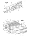
- One of the cheeks may then be positioned in abutment against the heat exchange zone 18 of one of the exchangers 1 and the other cheek 40 bears against the heat exchange zone 20 of the other exchanger 2 when the tubes 5, 10 and the metal strips 30 are combined, as is more particularly illustrated in FIG. figure 6 .
- the said cheeks are then acted in two opposite directions, thereby obtaining the desired offset for the tubes and the breaking of the residual connection between the heat exchange zones.
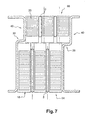
- the cheeks 40 are then in abutment against the heat exchange elements 64, 66 over their entire width, as illustrated in FIG. figure 7 .
- it may be a cheek deformable such as that described in figure 5 .
- the deformable connections 52 may have been previously obtained through cuts 54 made in the thickness of the metal sheet.
- the two parts 48 and 50 of the cheek are then assembled in abutment against the fins 30 before breaking the residual bonding zones of the heat exchange zones 18,20.
- the flange 46 is associated at the same time as the rest of the exchanger (tubes and fins) and absorbs, 1 thanks to its deformable bonds 52, the shearing movement produced by the separation of the two zones. heat exchange.
- the invention is not limited to the embodiments described above by way of example and extends to other variants.
- plastic manifolds each associated with a metal collector.
- a heat exchange module comprising two heat exchangers 1 and 2 (for example a cooling radiator and a condenser) intended to be traversed by different fluids.
- thermoelectric module which can also be called.
- multi-temperature exchanger in which the exchangers 1 and 2 are traversed by the same fluid, provided at two different temperatures from one exchanger to another.
- the invention finds particular application in the production of heat exchange modules for motor vehicles.
Abstract
Description
L'invention concerne un module d'échange de chaleur et un procédé de fabrication d'un tel module. Elle trouvera ses applications en particulier dans le domaine des véhicules automobiles.The invention relates to a heat exchange module and a method for manufacturing such a module. It will find its applications particularly in the field of motor vehicles.
On connaît du document
Cela étant, elle concerne plus particulièrement un module selon le préambule de la revendication 1.That being so, it relates more particularly to a module according to the preamble of
Il est connu d'utiliser, et notamment du document
Dans de tels modules, il est nécessaire d'éviter les ponts thermiques entre les échangeurs. Cette nécessité est d'autant plus grande que les deux échangeurs fonctionnent à des températures différentes. On peut citer comme exemple les modules d'échange de chaleur de véhicules automobiles qui comprennent un radiateur servant au refroidissement du moteur et un condenseur faisant partie du circuit de climatisation.In such modules, it is necessary to avoid thermal bridges between the exchangers. This need is all the greater as the two exchangers operate at different temperatures. An example of this is motor vehicle heat exchange modules which include a radiator for cooling the engine and a condenser forming part of the air conditioning circuit.
On parvient classiquement à réduire les ponts thermiques par des moyens divers, tels que la réalisation de fentes localisées, l'enlèvement de matière ou la réduction locale de l'épaisseur des ailettes. Ces moyens divers, s'ils réduisent les échanges thermiques, n'assurent toutefois pas un isolement thermique parfait comme cela serait le cas en absence de tout pont thermique.Classically, thermal bridging is achieved by various means, such as providing localized slots, removing material, or locally reducing the thickness of the fins. These various means, if they reduce heat exchange, do not provide a perfect thermal insulation as would be the case in the absence of any thermal bridge.
L'invention a précisément pour objet un module d'échange de chaleur qui remédie à ces inconvénients en permettant de supprimer le pont thermique entre les différents échangeurs d'un module d'échangeurs de chaleur.The subject of the invention is precisely a module for the exchange of heat that overcomes these disadvantages by allowing to remove the thermal bridge between the different heat exchanger module exchangers.
Ce but est atteint, conformément à l'invention, par le fait que le module comporte des ailettes d'échange de chaleur, notamment de refroidissement, constituée d'une bande comprenant une première zone d'échange de chaleur, destinée à coopérer avec les tubes du premier échangeur de chaleur, et une seconde zone d'échange de chaleur, destinée à coopérer avec les tubes du second échangeur de chaleur, et une zone d'affaiblissement, apte à autoriser sa séparation, en un premier élément comprenant ladite première zone d'échange de chaleur et un second élément comprenant ladite seconde zone d'échange de chaleur. Le module comprend en outre au moins une joue assemblée par brasage à la première zone d'échange de chaleur et à la seconde zone d'échange de chaleur.This object is achieved, in accordance with the invention, in that the module comprises fins for heat exchange, in particular for cooling, consisting of a strip comprising a first heat exchange zone intended to cooperate with the tubes of the first heat exchanger, and a second heat exchange zone, intended to cooperate with the tubes of the second heat exchanger, and a weakening zone, capable of permitting its separation, into a first element comprising said first zone; heat exchanger and a second element comprising said second heat exchange zone. The module further comprises at least one cheek assembled by soldering to the first heat exchange zone and the second heat exchange zone.
Grâce à ces caractéristiques, on dispose d'une ailette qui permet l'assemblage simultané des composants de deux échangeurs, puis la séparation de la liaison entre ladite première et seconde zones d'échange.Thanks to these features, there is a fin which allows the simultaneous assembly of the components of two exchangers, and the separation of the connection between said first and second exchange zones.
On peut ainsi obtenir des multi-échangeurs qui offrent l'avantage de ne présenter aucun pont thermique entre les zones d'échange de chaleur de l'ailette puisqu'il n'existe plus de liaisons métalliques résiduelles entre elles, par lesquelles un transfert de chaleur pourrait se faire.It is thus possible to obtain multi-exchangers which have the advantage of not having any thermal bridge between the heat exchange zones of the fin since there is no longer any residual metal bonds between them, by which a transfer of heat heat could be done.
Selon un mode de réalisation avantageux, la bande de l'ailette conforme à l'invention présente une forme ondulée et la ladite zone d'affaiblissement est constituée d'une fente rectiligne, par exemple obtenue par cisaillement, interrompue au niveau de certaine des faces des ondulations par au moins une liaison résiduelle, prévue entre ladite première et la dite seconde zone d'échange de chaleur.According to an advantageous embodiment, the strip of the fin according to the invention has a corrugated shape and the said weakening zone consists of a straight slot, for example obtained by shear, interrupted at some of the faces. corrugations by at least one residual connection, provided between said first and said second heat exchange zone.
A titre d'exemple, les faces des ondulations présentent une hauteur H et ladite liaison résiduelle, prévue à mi-hauteur, présente une hauteur h comprise entre H/5 et H/30, notamment d'environ 0,5 mm.For example, the faces of the corrugations have a height H and said residual connection, provided at mid-height, has a height h between H / 5 and H / 30, in particular about 0.5 mm.
Selon une variante, les ailettes sont planes. Elles comportent alors des perforations dans lesquelles les tubes sont introduits.According to one variant, the fins are flat. They then comprise perforations in which the tubes are introduced.
Ladite bande présente une largeur, par exemple, sensiblement égale à la somme des largeurs des tubes du premier et du second échangeurs tandis que ladite première et ladite seconde zone d'échange de chaleur de ladite bande présentent une largeur correspondant respectivement à la largeur des tubes du premier et du second échangeur.Said strip has a width, for example, substantially equal to the sum of the widths of the tubes of the first and second heat exchangers while said first and said second heat exchange zone of said strip have a width respectively corresponding to the width of the tubes first and second heat exchanger.
Dans un premier exemple, les tubes des échangeurs dudit multi-échangeur sont décalés les uns des autres selon une direction orthogonale aux dits tubes et lesdites joues présentent un décalage de niveau équivalent entre le premier et le second échangeur.In a first example, the tubes of the exchangers of said multi-exchanger are offset from each other in a direction orthogonal to said tubes and said cheeks have a shift of equivalent level between the first and the second exchanger.
Dans un second exemple lesdites joues comprennent deux parties reliées entre elles par des liaisons déformables et assemblées par brasage respectivement à la première et à la seconde zones d'échange de chaleur.In a second example, said cheeks comprise two parts interconnected by deformable connections and soldered together respectively to the first and second heat exchange zones.
Dans un tel exemple, l'une des parties de la joue assemblée à l'une des zones d'échange de chaleur pourra comprendre au moins une excroissance assujettie par brasage à l'autre zone d'échange de chaleur.In such an example, one of the parts of the cheek assembled at one of the heat exchange zones may comprise at least one excrescence soldered to the other heat exchange zone.
On peut d'ailleurs noter que de telles joues trouvent leur utilité dans tout type de module sans qu'il s'agisse obligatoirement de modules munis d'ailettes conformes à l'invention. Ces joues présentent en effet par leur structure des capacités de limitations des transferts thermiques d'un échangeur à l'autre.It can also be noted that such cheeks find their use in any type of module without necessarily being modules with fins conforming to the invention. These cheeks have in fact their structure capacity limitations of heat transfer from one exchanger to another.
L'invention concerne encore un procédé de fabrication d'un module d'échange de chaleur comprenant au moins deux échangeurs de chaleur, chaque échangeur comprenant des tubes de circulation de fluide généralement plats et régulièrement espacés, ayant une largeur, et des éléments de refroidissement associées à ces tubes caractérisé en ce que :
- on prévoit des bandes de tôle,
- on réalise un affaiblissement des bandes de tôle afin de limiter une première zone d'échange de chaleur destinée à être associée aux tubes du premier échangeur et une seconde zone d'échange de chaleur destinée à être associée aux tubes du second échangeur de chaleur, cet affaiblissement laissant subsister une liaison résiduelle entre la première zone d'échange de chaleur et la seconde zone d'échange de chaleur,
- on associe les bandes de tôle aux tubes des échangeurs,
- on rompt les liaisons résiduelles entre la première zone d'échange de chaleur et la seconde zone d'échange de chaleur de manière à les séparer entièrement,
- on assemble les échangeurs par brasage, et
- on assemble lesdits échangeurs (1,2) entre eux par ladite joue, lors du brasage.
- sheet metal strips are provided,
- a weakening of the sheet metal strips is achieved in order to limit a first heat exchange zone intended to be associated with the tubes of the first heat exchanger and a second heat exchange zone intended to be associated with the tubes of the second heat exchanger, this weakening leaving a residual connection between the first heat exchange zone and the second heat exchange zone,
- we associate the strips of sheet metal to the tubes of the exchangers,
- the residual connections between the first heat exchange zone and the second heat exchange zone are broken off so as to separate them completely,
- the exchangers are assembled by brazing, and
- said exchangers (1,2) are assembled together by said cheek during brazing.
Après réalisation dudit affaiblissement, ladite bande de tôle constitue, par exemple, une ailette telle que définie plus haut.After completion of said weakening, said sheet metal strip constitutes, for example, a fin as defined above.
Avantageusement, l'opération de rupture des liaisons résiduelles est réalisée avant le brasage, lors de l'opération d'association des bandes de tôle aux tubes.Advantageously, the breaking operation of the residual bonds is performed before brazing, during the operation of association of the sheet metal strips with the tubes.
De préférence, l'on conforme les bandes de tôle de manière à leur donner une forme ondulée, l'association des bandes de tôle aux tubes de l'échangeur se faisant par introduction des bandes de tôle ondulées entre les tubes.Preferably, the sheet metal strips are shaped so as to give them a corrugated shape, the association of the sheet metal strips with the tubes of the exchanger being done by introducing the corrugated sheet metal strips between the tubes.
Dans ce cas, on réalise en une seule opération les intercalaires ondulés de tous les échangeurs du module d'échange de chaleur, ce qui permet une augmentation de la rapidité de fabrication sans augmentation simultanée de la vitesse de formage. Par suite, les caractéristiques géométriques des intercalaires peuvent être maintenues dans de faibles tolérances de fabrication, ce qui facilite leur introduction entre les tubes sans problème d'appariement.In this case, the corrugated spacers of all the exchangers of the heat exchange module are made in a single operation, which makes it possible to increase the speed of manufacture without simultaneously increasing the forming speed. As a result, the geometrical characteristics of the spacers can be maintained within low manufacturing tolerances, which facilitates their introduction between the tubes without problems of matching.
Avantageusement, on réalise ladite liaison résiduelle lors de la conformation des bandes de tôles sous forme ondulée, ceci en réalisant une fente discontinue dans les bandes de tôle, par exemple par cisaillement.Advantageously, said residual connection is made during the conformation of the corrugated sheet metal strips, this by producing a discontinuous slot in the sheet metal strips, for example by shearing.
Alternativement, l'affaiblissement des bandes de tôle pourra être réalisé par enlèvement de matière ou par réalisation de fentes longitudinales, avant conformation.Alternatively, the weakening of the metal strips may be achieved by removal of material or by producing longitudinal slots, before shaping.
Avantageusement, on rompt les liaisons résiduelles par déplacement des échangeurs l'un par rapport à l'autre, notamment selon un mouvement de cisaillement.Advantageously, the residual bonds are broken by displacement of the exchangers relative to each other, in particular according to a shearing movement.
On assemble les joues déformables telles qu'évoquées plus haut au reste du module, par exemple, lors de l'association des tubes et des bandes de tôles présentant les zones d'échange de chaleur. En effet, grâce à leur caractère déformable, elles pourront supporter l'opération de séparation desdites zones d'échange de chaleur.The deformable cheeks as mentioned above are assembled to the remainder of the module, for example, when the tubes and the strips of metal sheets having the heat exchange zones are combined. Indeed, thanks to their deformable nature, they can support the operation of separation of said heat exchange zones.
S'il s'agit d'un multi-échangeurs à tubes décalés, muni de joues présentant un décalage équivalent à celui des tubes, l'une des joues pourra être positionnée en appui contre la zone d'échange de chaleur de l'un des échangeurs et l'autre en appui contre la zone d'échange de chaleur de l'autre échangeur, lors de l'association des tubes et des bandes de tôles. On agira alors sur lesdites joues selon deux directions opposées en obtenant de la sorte le décalage voulu pour les tubes et la rupture de la liaison résiduelle entre les zones d'échange de chaleur.If it is a multi-exchanger tube offset, provided with cheeks having a shift equivalent to that of the tubes, one of the cheeks may be positioned in abutment against the heat exchange zone of one of the exchangers and the other in support against the heat exchange zone of the other heat exchanger, during the combination of tubes and strips of plate. It will then act on said cheeks in two opposite directions, thereby obtaining the desired offset for the tubes and breaking the residual bond between the heat exchange zones.
D'autres caractéristiques et avantages de la présente invention apparaîtront encore à la lecture de la description qui suit d'exemples de réalisation donnés à titre illustratif en référence aux figures annexées. Sur ces figures :
- la
Figure 1 est une vue partielle en perspective d'une ailette pour un module conforme à l'invention; - la
Figure 2 illustre un détail de la zone repéré II à lafigure 1 ; - la
Figure 3 est une vue en perspective d'un module conforme à l'invention; - la
Figure 4 illustre en perspective une variante de réalisation d'un élément d'un module conforme à l'invention; - la
Figure 5 illustre en perspective une étape d'un procédé, conforme à l'invention, de fabrication d'un module d'échangeur de chaleur; - la
Figure 6 détaille selon un plan de coupe transversale la position relative des différents composants illustrés à lafigure 5 , dans un premier état ; - la
Figure 7 détaille selon un plan de coupe transversale la position relative des différents composants illustrés à lafigure 5 , dans un second état.
- the
Figure 1 is a partial perspective view of a fin for a module according to the invention; - the
Figure 2 illustrates a detail of the area marked II to thefigure 1 ; - the
Figure 3 is a perspective view of a module according to the invention; - the
Figure 4 illustrates in perspective an alternative embodiment of an element of a module according to the invention; - the
Figure 5 illustrates in perspective a step of a method, according to the invention, for manufacturing a heat exchanger module; - the
Figure 6 details in a cross-sectional plan the relative position of the various components illustrated in FIG.figure 5 in a first state; - the
Figure 7 details in a cross-sectional plan the relative position of the various components illustrated in FIG.figure 5 in a second state.
Aux
Chaque zone d'échange de chaleur 18,20 pourra être munie de moyens permettant de perturber l'écoulement de l'air, aussi appelées persiennes 60,62, connues de l'homme de l'art.Each
Avantageusement, la configuration desdites persiennes est adaptée au type d'échangeur équipé. Elles pourront, par exemple, être orientées tête-bêche de part et d'autre d'un axe de symétrie, ceci dans chaque zone d'échange de chaleur 18, 20. Autrement dit, dans la première zone d'échange de chaleur 18, il est prévu dé part et d'autre d'un premier axe de symétrie des persiennes d'orientation opposée. De même dans la seconde zone d'échange de chaleur 20, de part et d'autre d'un second axe de symétrie. Le nombre de persienne de la première zone d'échange de chaleur et celui de la seconde d'échange de -chaleur pourra être différent.Advantageously, the configuration of said louvers is adapted to the type of exchanger equipped. They may, for example, be oriented head to tail on either side of an axis of symmetry, this in each
Selon l'invention, ladite bande comprend une zone d'affaiblissement 22, apte à autoriser sa séparation en un premier élément comprenant ladite première zone d'échange de chaleur 18 et un second élément comprenant ladite seconde zone d'échange de chaleur 20.According to the invention, said band comprises a weakening
On remarquera que les largeurs des zones 18 et 20 ne sont pas nécessairement égales. La largeur de chacune de ces zones correspond à la largeur des tubes de circulation de fluide de chacun des échangeurs avec lesquels l'ailette est destinée à coopérer. Si les tubes du premier échangeur sont plus larges que les tubes du second échangeur, la zone d'échange de chaleur 18 destinée à établir un échange de chaleur avec les tubes du premier échangeur pourra être plus large que la zone d'échange de chaleur 20 destinée à établir un échange de chaleur avec les tubes du second échangeur. La zone d'affaiblissement 22 de l'ailette pourra ainsi être décalée par rapport à l'axe de symétrie de celle-ci.It will be noted that the widths of the
Selon le mode de réalisation illustré, ladite bande 30 présente une forme ondulée et la ladite zone d'affaiblissement 22 est constituée d'une fente rectiligne interrompue au niveau de certaine des faces des ondulations par au moins une liaison résiduelle 34, prévue entre ladite première et la dite seconde zone d'échange de chaleur. Le ratio du nombre de faces avec liaison résiduelle sur le nombre de faces sans liaison résiduelle pourra varier de 1/7 à 1/20. Il pourra être, notamment de 1/10.According to the illustrated embodiment, said
Les deux zones d'échange de chaleur 18 et 20 sont ainsi séparées l'une de l'autre par des lumières 26 interrompues à intervalles réguliers par des languettes de tôle 34, notamment perpendiculaire à l'axe longitudinal de la bande de tôle 30.The two
On réalise ainsi un affaiblissement de la bande de tôle, cet affaiblissement laissant subsister des liaisons résiduelles constituées par les languettes entre la première zone d'échange de chaleur 18 et la seconde zone d'échange de chaleur 20. Lesdites lumières présentent, par exemple, une largeur inférieure à 0,5 mm, voire 0,3 mm, voire 0,1 mm, ou encore une largeur nulle ou non mesurable, ledit affaiblissement résultant d'une simple découpe sans enlèvement de matière.A weakening of the sheet metal strip is thus achieved, this weakening leaving residual connections formed by the tabs between the first
Les faces des ondulations présentent, notamment, une hauteur H et ladite liaison résiduelle, présente une hauteur h comprise, par exemple, entre H/5 et H/.30, notamment égale à H/12. Elle pourra être prévue à mi-hauteur ou dans les rayons.The faces of the corrugations have, in particular, a height H and said residual link has a height h, for example between H / 5 and H / .30, especially equal to H / 12. It can be planned at mid-height or on the shelves.
Le module d'échange de chaleur représenté sur la
Le radiateur 1 est constitué de façon connue d'un faisceau de tubes de circulation de fluide 5 montés entre deux boîtes collectrices 6 (une seule boîte a été représentée), les deux boites collectrices 6 étant disposées le long de deux côtés parallèles du faisceau de tubes et munies de tubulures d'entrée 8 et de sortie du fluide de refroidissement.The
Le condenseur 2 est également constitué d'un faisceau de tubes de circulation de fluide 10 montés entre deux boîtes collectrices 12 (une seule boîte a été représentée), les boites collectrices étant disposées le long de deux côtés parallèles du faisceau et munies de tubulures d'entrée et de sortie du fluide réfrigérant (non représentées).The
Les tubes de chacun des échangeurs sont, par exemple, en aluminium.The tubes of each of the exchangers are, for example, aluminum.
Selon l'invention, ledit module comprend également des ailettes telles que décrites plus haut, lesdits premiers et seconds éléments 64,66 desdites ailettes, prévus séparés l'un de l'autre, étant respectivement associés aux tubes 5,10 du premier et du second échangeur. La trace de la liaison résiduelle 34 rompue, bien que visible, n'a pas été représentée.According to the invention, said module also comprises fins as described above, said first and
Dans le mode de réalisation représenté, les ailettes du module d'échange de chaleur sont constituées par des intercalaires de tôles ondulées disposés entre les tubes 5 et les tubes 10'In the embodiment shown, the fins of the heat exchange module are constituted by interleaved corrugated sheets disposed between the
La boîte collectrice 6 de l'échangeur 1 est formée à partir de feuilles métalliques, avantageusement en aluminium, conformées par des opérations classiques de découpage et d'emboutissage.The manifold 6 of the
Elles comportent un fond 80 qui est généralement plat et de forme rectangulaire allongée. Ce fond est destiné à constituer la plaque collectrice, encore appelée «plaque à trous», de la boîte collectrice 6. Il comporte à cet effet une pluralité de trous 82 espacés de forme allongée destinés. à recevoir les tubes 5 de l'échangeur 1. La boîte collectrice 6 comprend, en outre, des flancs latéraux 36 repliés en vis-à-vis qui sont généralement plans et parallèles entre eux. Les flancs 36 se raccordent sensiblement perpendiculairement au fond par deux lignes de pliage qui sont parallèles entre elles. La tubulure 8 est aménagée dans l'un des flancs latéraux 36.They have a bottom 80 which is generally flat and elongated rectangular shape. This bottom is intended to form the collector plate, also called "plate with holes", of the header box 6. It comprises for this purpose a plurality of spaced
La boîte collectrice 6 est fermée par un feuillard métallique de largeur donnée qui possède des génératrices parallèles. Ce feuillard peut venir s'emboîter entre les flancs latéraux 36 de la boîte collectrice 6 pour former un ensemble prêt à être brasé en même temps que la tubulure 8.The manifold 6 is closed by a metal strip of given width which has parallel generatrices. This strip can be fitted between the
La boîte collectrice 12 de l'échangeur 2 présente la forme générale d'un cylindre allongé muni de perforations destinées à recevoir les tubes 10 de l'échangeur.The
Avantageusement, ledit module d'échange de chaleur conforme à l'invention comprend en outre au moins une joue 40 assemblée par brasage à la première zone d'échange de chaleur 18 et à la secondes zone d'échange de chaleur 20. Ladite joue est constituée, par exemple, par une plaque métallique 37 de forme générale rectangulaire.Advantageously, said heat exchange module according to the invention further comprises at least one
Selon le mode de réalisation illustré, les tubes 5,10 des échangeurs sont décalés les uns des autres selon une direction orthogonale aux dits tubes et les joues 40 présentent un décalage 39 de niveau équivalent entre le premier et le second échangeur 1,2.According to the illustrated embodiment, the
Comme illustré à la
Plus précisément, la joue 46 comprend deux parties allongées adjacentes, à savoir une partie 48 et une partie 50 reliées entre elles par les liaisons déformables 52. La partie 48 est propre à être assemblée à la première zone d'échange de chaleur 18, c'est-à-dire aux intercalaires de l'échangeur 1, tandis que la partie 50 est propre à être assemblée à la deuxième zone d'échange de chaleur 20, c'est-à-dire aux intercalaires de l'échangeur 2.More specifically, the
L'une des parties 50 de la joue assemblée à l'une des zones d'échange de chaleur 20 comprend au moins une excroissance 68 assujettie par brasage à l'autre zone d'échange de chaleur 18.One of the
L'invention concerne également un procédé de fabrication d'un module d'échange de chaleur comprenant au moins deux échangeurs de chaleur 1,2, chaque échangeur comprenant des tubes de circulation de fluide 5, 10 généralement plats et régulièrement espacés, ayant une largeur, et des éléments de refroidissement 64,66 associées à ces tubes 5, 10.The invention also relates to a method for manufacturing a heat exchange module comprising at least two
On réalise les opérations suivante
- on prévoit des bandes de tôle 30,
- on
réalise un affaiblissement 22 des bandes de tôle 30 afin de limiter une première zone d'échange de chaleur 18 destinée à être associée auxtubes 5 du premier échangeur 1 et une seconde zone d'échange de chaleur 20 destinée à être associée auxtubes 10 du second échangeur de chaleur 2, cet affaiblissement laissant subsister une liaison résiduelle 34 entre la première zone d'échange de chaleur 18 et la seconde zone d'échange de chaleur 20, - on associe les bandes de tôle 30 aux
tubes 5 et 10 des échangeurs 1, 2, - on rompt les liaisons résiduelles 34 entre la première zone d'échange de chaleur 18 et la seconde zone d'échange de chaleur 20 de manière à les séparer entièrement,
- on assemble les échangeurs 1, 2 par brasage.
- sheet metal strips 30 are provided,
- the sheet metal strips 30 are weakened in order to limit a first
heat exchange zone 18 intended to be associated with thetubes 5 of thefirst heat exchanger 1 and a secondheat exchange zone 20 intended to be associated with thetubes 10 of thesecond heat exchanger 2, this weakening leaving aresidual connection 34 remaining between the firstheat exchange zone 18 and the secondheat exchange zone 20, - the sheet metal strips 30 are associated with the
tubes exchangers - the
residual connections 34 are broken between the firstheat exchange zone 18 and the secondheat exchange zone 20 so as to separate them completely, - the
exchangers
Après réalisation dudit affaiblissement, ladite bande de tôle constitue, par exemple, une ailette telle que définie plus haut.After completion of said weakening, said sheet metal strip constitutes, for example, a fin as defined above.
Avantageusement, avant assemblage, on conforme les bandes de tôle 30 de manière à leur donner une forme ondulée, l'association des bandes de tôle 30 aux tubes des échangeurs de chaleur se faisant par introduction des bandes de tôle entre les tubes 5,10.Advantageously, before assembly, the sheet metal strips 30 are conformed so as to give them a corrugated shape, the association of the sheet metal strips 30 to the tubes of the heat exchangers being done by introduction of the sheet metal strips between the
A la
Plus précisément, après insertion des ailettes ondulées 30 entre les tubes 5 et les tubes 10, la zone d'échange de chaleur 18 et la zone d'échange de chaleur 20 sont encore reliées entre elles par les languettes de tôle 34.More precisely, after insertion of the
On pourra rompre les liaisons résiduelles 34 par déplacement des échangeurs 1,2 l'un par rapport à l'autre. Plus précisément, la séparation des zones d'échange de chaleur 18 et 20 pourra être réalisée par un mouvement de cisaillement en exerçant sur le premier échangeur un effort selon une première direction F1 et sur le second échangeur un effort selon une seconde direction F2, parallèle et opposée à la direction F1.The
Une telle opération pourra être réalisée par un outillage comprenant une paire de mâchoires.41 et 42 propres à enserrer la zone d'échange de chaleur 18 (tubes 5 et éléments d'échange de chaleur 64) de l'échangeur de chaleur 1, et une autre paire de mâchoire 43 et 44 propres à enserrer la zone d'échange de chaleur 20 (tubes 10 et éléments d'échange de chaleur 66) de l'échangeur de chaleur 2, lesdites paires de mâchoires étant aptes à se déplacer selon les directions F1,F2.Such an operation may be performed by a tool comprising a pair of jaws.41 and 42 adapted to grip the heat exchange zone 18 (
On réalise ladite liaison résiduelle 34, par exemples en réalisant une fente discontinue dans les bandes de tôle 30 lors de leur conformation sous forme ondulée.The said
On dispose une joue commune 40 aux deux échangeurs en vis-à-vis des premières 18 et seconde 20 zones d'échange de chaleur et on assemble lesdits échangeurs 1,2 entre eux par ladite joue, lors du brasage.There is a
Comme illustré aux
L'une des joues pourra alors être positionnée en appui contre la zone d'échange de chaleur 18 de l'un des échangeurs 1 et l'autre joue 40 en appui contre la zone d'échange de chaleur 20 de l'autre échangeur 2, lors de l'association des tubes 5,10 et des bandes de tôles 30, comme plus particulièrement illustré à la
On agit ensuite sur lesdites joues selon deux directions opposées en obtenant de la sorte le décalage voulu pour les tubes et la rupture de la liaison résiduelle entre les zones d'échange de chaleur. Les joues 40 sont alors en appui contre les éléments d'échange de chaleur 64,66 sur toute leur largeur, comme illustré à la
Selon un autre mode de réalisation, il pourra s'agir d'une joue déformable telle que celle décrite à la
Dans ce cas, les liaisons déformables 52 auront pu être préalablement obtenues grâce à des découpes 54 réalisées dans l'épaisseur de la tôle métallique.In this case, the
Les deux parties 48 et 50 de la joue sont alors assemblées en appui contre les ailettes 30 avant rupture des zones de liaison résiduelles des zones d'échange de chaleur 18,20.The two
Lorsque les zones de liaison résiduelles 34 sont rompues pour séparer les deux zones d'échange de chaleur 18 et 20, les parties 48 et 50 de la joue restent solidarisées aux deux zones d'échange de chaleur, mais se trouvent écartées l'une de l'autre. Cependant, ces deux parties 48 et 50 restent solidaires l'une de l'autre grâce aux liaisons déformables 52.When the
Ainsi, dans ce mode de réalisation, la joue 46 est associée en même temps que le reste de l'échangeur (tubes et ailettes) et absorbe, 1 grâce à ses liaisons déformables 52, le mouvement de cisaillement produit par la séparation des deux zones d'échange de chaleur.Thus, in this embodiment, the
L'invention n'est pas limitée aux formes de réalisation décrites précédemment à titre d'exemple et s'étend à d'autres variantes. Ainsi, au lieu d'utiliser des boites collectrices complètement métalliques, on pourrait utiliser des boîtes collectrices en matière plastique associées chacune à un collecteur métallique.The invention is not limited to the embodiments described above by way of example and extends to other variants. Thus, instead of using completely metal collecting boxes, one could use plastic manifolds each associated with a metal collector.
Par ailleurs, on a décrit ici un module d'échange de chaleur comprenant deux échangeurs de chaleur 1 et 2 (par exemple un radiateur de refroidissement et un condenseur) destinés à être parcourus par des fluides différents.Moreover, a heat exchange module has been described here comprising two
Il entre aussi dans le cadre de l'invention de réaliser un module d'échange de chaleur, que l'on peut aussi appeler. échangeur multi-températures, dans lequel les échangeurs 1 et 2 sont parcourus par le même fluide, prévus à deux températures différentes d'un échangeur à l'autre.It is also within the scope of the invention to provide a heat exchange module, which can also be called. multi-temperature exchanger, in which the
Alternativement, plutôt que de constituer un module comprenant une joue commune, on pourra assujettir lesdits échangeurs l'un à l'autre sous la forme d'un module, après brasage, grâce à des moyens de liaison rapportés.Alternatively, rather than constituting a module comprising a common cheek, it will be able to subject said exchangers to each other in the form of a module, after soldering, by means of reported connection means.
L'invention trouve une application particulière à la réalisation de modules d'échange de chaleur pour véhicules automobiles.The invention finds particular application in the production of heat exchange modules for motor vehicles.
Claims (13)
- Heat exchange module comprising at least one first and one second heat exchanger (1, 2), each exchanger comprising fluid circulation tubes (5, 10), generally flat, uniformly spaced, having a width, and heat exchange, particularly cooling, fins consisting of a strip (30) comprising a first heat exchange zone (18) intended to collaborate with the tubes of the first heat exchanger, and a second heat exchange zone (20) intended to collaborate with the tubes of the second heat exchanger, the said module further comprising at least one endplate (40, 46) assembled by brazing to the first heat exchange zone (18) and to the second heat exchange zone (20), characterized in that, prior to assembly, the said strip comprises a zone of weakness (22) able to allow it to be separated into a first element (64) comprising the said first heat exchange zone (18) and a second element (66) comprising the said second heat exchange zone (20) and, after assembly, the said first and second elements (64, 66) of the said fins, designed to be separated from one another, are respectively associated with the tubes (5, 10) of the first and of the second exchanger.
- Module according to Claim 1, in which the said strip (30) has a wavy shape and the said zone of weakness consists of a rectilinear slit interrupted at some of the faces of the waves by at least one residual connection (34) provided between the said first and the said second heat exchange zones.
- Module according to Claim 2, in which the faces of the waves have a height H and the said residual connection, provided mid-way up the height, has a height h of between H/5 and H/30.
- Module according to Claim 2, in which the said slit results from a simple cut without the removal of material.
- Heat exchange module according to one of the preceding claims, in which the tubes (5, 10) of the exchangers are offset from one another in a direction orthogonal to the said tubes and the endplates (40) exhibit an equivalent offset in level between the first and second exchangers (1, 2) .
- Heat exchange module according to one of the preceding claims, in which the endplates (46) comprise two parts (48; 50) joined together by deformable connections (52) and assembled by brazing to the first (18) and to the second (20) heat exchange zones respectively.
- Heat exchange module according to Claim 6, in which one of the parts (50) of the endplate assembled to one of the heat exchange zones (20) comprises at least one protrusion (68) secured by brazing to the other heat exchange zone (18).
- Heat exchange module according to any one of the preceding claims, in which the first exchanger is a radiator and the second exchanger is a condenser.
- Method of manufacturing a module according to any one of the preceding claims, characterized in that:- the said strips of sheet (30) are provided,- a weakness (22) is created in the strips of sheet (30) so as to limit the said first heat exchange zone (18) intended to be associated with the tubes of the first exchanger (5) and the said second heat exchange zone (20) intended to be associated with the tubes (10) of the second heat exchanger (2), this weakness leaving a remanent residual connection (34) between the first heat exchange zone (18) and the second heat exchange zone (20),- the strips of sheet (30) are associated with the tubes (5 and 10) of the exchangers (1, 2),- the residual connections (34) between the first heat exchange zone (18) and the second heat exchange zone (20) are broken so as to completely separate the zones,- the exchangers (1, 2) are assembled by brazing,- an endplate (40, 46) common to the two exchangers is positioned facing the first (18) and second (20) heat exchange zones, and- the said exchangers (1, 2) are assembled with one another via the said endplate, during the brazing operation.
- Method according to Claim 9, in which the operation of breaking the residual connections is performed during the operation of associating the strips of sheet with the tubes.
- Method according to one of Claims 9 and 10, in which the strips of sheet (30) are shaped in such a way as to give them a wavy shape, the strips of sheet (30) being associated with the tubes of the heat exchangers by inserting the strips of sheet between the tubes (5, 10).
- Method according to Claim 11, in which the said residual connection is created by making a discontinuous slit in the strips of sheet (30) while they are being given a wavy shape.
- Method according to one of Claims 9 to 12, in which the residual connections (34) are broken by moving the exchangers (1, 2) one relative to the other.
Applications Claiming Priority (3)
| Application Number | Priority Date | Filing Date | Title |
|---|---|---|---|
| FR0216740A FR2849174B1 (en) | 2002-12-23 | 2002-12-23 | HEAT EXCHANGE FINISH, ESPECIALLY COOLING, HEAT EXCHANGE MODULE COMPRISING SUCH FIN AND METHOD OF MANUFACTURING HEAT EXCHANGERS USING THE SAME |
| FR0216740 | 2002-12-23 | ||
| PCT/FR2003/003750 WO2004065872A1 (en) | 2002-12-23 | 2003-12-16 | Method of producing a heat exchanger module |
Publications (2)
| Publication Number | Publication Date |
|---|---|
| EP1579162A1 EP1579162A1 (en) | 2005-09-28 |
| EP1579162B1 true EP1579162B1 (en) | 2009-11-04 |
Family
ID=32406537
Family Applications (1)
| Application Number | Title | Priority Date | Filing Date |
|---|---|---|---|
| EP03815413A Expired - Lifetime EP1579162B1 (en) | 2002-12-23 | 2003-12-16 | Heat exchanger module and method of producing |
Country Status (8)
| Country | Link |
|---|---|
| US (1) | US7905277B2 (en) |
| EP (1) | EP1579162B1 (en) |
| JP (1) | JP4459062B2 (en) |
| AT (1) | ATE447692T1 (en) |
| AU (1) | AU2003300631A1 (en) |
| DE (1) | DE60329940D1 (en) |
| FR (1) | FR2849174B1 (en) |
| WO (1) | WO2004065872A1 (en) |
Families Citing this family (10)
| Publication number | Priority date | Publication date | Assignee | Title |
|---|---|---|---|---|
| JP4683987B2 (en) | 2005-04-14 | 2011-05-18 | カルソニックカンセイ株式会社 | Fin structure of integrated heat exchanger |
| DE102011082797A1 (en) * | 2011-09-15 | 2013-03-21 | Behr Gmbh & Co. Kg | Heat exchanger for cooling charge air |
| FR2987673B1 (en) * | 2012-03-01 | 2018-06-15 | Valeo Systemes Thermiques | METHOD FOR MANUFACTURING A HEAT EXCHANGER TUBE FOR A VEHICLE, ESPECIALLY A MOTOR VEHICLE, TUBE OBTAINED BY SAID METHOD AND HEAT EXCHANGER COMPRISING SUCH A TUBE |
| US10281221B2 (en) | 2012-07-18 | 2019-05-07 | Fab Tek Logic, Llc | Removable heatsink fin assembly |
| CA2821290C (en) | 2012-07-18 | 2019-02-26 | Fab Tek Logic, Llc | Removable radiator fin assembly |
| US20140262143A1 (en) * | 2013-03-15 | 2014-09-18 | Rodney Koch | Single exchanger hvac unit and power machines using the same |
| US10508862B2 (en) * | 2013-03-15 | 2019-12-17 | Carrier Corporation | Heat exchanger for air-cooled chiller |
| JP6687967B2 (en) | 2014-03-24 | 2020-04-28 | 株式会社デンソー | Heat exchanger |
| CN107218822B (en) * | 2016-03-21 | 2019-04-19 | 丹佛斯微通道换热器(嘉兴)有限公司 | Heat exchanger and air-conditioning system |
| FR3090837B1 (en) * | 2018-12-19 | 2021-01-15 | Valeo Systemes Thermiques | Heat exchanger with brazed end cheek |
Family Cites Families (16)
| Publication number | Priority date | Publication date | Assignee | Title |
|---|---|---|---|---|
| US4173998A (en) * | 1978-02-16 | 1979-11-13 | Carrier Corporation | Formed coil assembly |
| IE58157B1 (en) * | 1984-10-02 | 1993-07-28 | Badsey Ltd | Heat exchanger fin array |
| DE4203212A1 (en) * | 1992-02-05 | 1993-10-14 | Behr Gmbh & Co | Mfr. of heat exchangers - involves formed ribs and tubes, which are stacked into large block, and this is divided into individual blocks |
| JP3312986B2 (en) * | 1994-02-25 | 2002-08-12 | 東芝キヤリア株式会社 | Heat exchanger and method of manufacturing heat exchanger |
| US5992514A (en) * | 1995-11-13 | 1999-11-30 | Denso Corporation | Heat exchanger having several exchanging portions |
| JP4019113B2 (en) * | 1997-11-13 | 2007-12-12 | 株式会社ティラド | Integrated heat exchanger fin and method of manufacturing the same |
| US6237676B1 (en) * | 1998-04-28 | 2001-05-29 | Denso Corporation | Heat exchanger for vehicle air conditioner |
| US6328098B1 (en) * | 1998-11-10 | 2001-12-11 | Valeo Inc. | Side member for heat exchanger and heat exchanger incorporating side plate |
| JP4379967B2 (en) * | 1999-03-30 | 2009-12-09 | 株式会社デンソー | Double heat exchanger |
| JP4207331B2 (en) * | 1999-09-29 | 2009-01-14 | 株式会社デンソー | Double heat exchanger |
| JP4482991B2 (en) * | 1999-12-14 | 2010-06-16 | 株式会社デンソー | Double heat exchanger |
| US6561264B2 (en) * | 2000-03-16 | 2003-05-13 | Denso Corporation | Compound heat exhanger having cooling fins introducing different heat exhanging performances within heat exchanging core portion |
| FR2812382B1 (en) * | 2000-07-25 | 2003-02-07 | Valeo Thermique Moteur Sa | METHOD FOR MANUFACTURING A HEAT EXCHANGER FIN, FINS ACCORDING TO THE METHOD AND EXCHANGE MODULE COMPRISING THESE FINS |
| JP4041654B2 (en) * | 2001-01-31 | 2008-01-30 | カルソニックカンセイ株式会社 | Louver fin of heat exchanger, heat exchanger thereof, and method of assembling the louver fin |
| US20030075307A1 (en) * | 2001-10-22 | 2003-04-24 | Heatcraft, Inc. | Exchanger of thermal energy with multiple cores and a thermal barrier |
| JP4029000B2 (en) * | 2002-01-25 | 2008-01-09 | カルソニックカンセイ株式会社 | Manufacturing method of integrated heat exchanger and integrated heat exchanger |
-
2002
- 2002-12-23 FR FR0216740A patent/FR2849174B1/en not_active Expired - Fee Related
-
2003
- 2003-12-16 AT AT03815413T patent/ATE447692T1/en not_active IP Right Cessation
- 2003-12-16 JP JP2004567011A patent/JP4459062B2/en not_active Expired - Fee Related
- 2003-12-16 EP EP03815413A patent/EP1579162B1/en not_active Expired - Lifetime
- 2003-12-16 WO PCT/FR2003/003750 patent/WO2004065872A1/en active Application Filing
- 2003-12-16 AU AU2003300631A patent/AU2003300631A1/en not_active Abandoned
- 2003-12-16 DE DE60329940T patent/DE60329940D1/en not_active Expired - Lifetime
- 2003-12-16 US US10/539,991 patent/US7905277B2/en not_active Expired - Fee Related
Also Published As
| Publication number | Publication date |
|---|---|
| AU2003300631A1 (en) | 2004-08-13 |
| EP1579162A1 (en) | 2005-09-28 |
| WO2004065872A1 (en) | 2004-08-05 |
| FR2849174B1 (en) | 2006-01-06 |
| FR2849174A1 (en) | 2004-06-25 |
| JP2006511785A (en) | 2006-04-06 |
| ATE447692T1 (en) | 2009-11-15 |
| DE60329940D1 (en) | 2009-12-17 |
| US20060249277A1 (en) | 2006-11-09 |
| US7905277B2 (en) | 2011-03-15 |
| JP4459062B2 (en) | 2010-04-28 |
Similar Documents
| Publication | Publication Date | Title |
|---|---|---|
| EP1176378B1 (en) | Process for manufacturing a fin for a heat exchanger, fins according to said process and heat exchange module with such fins | |
| EP2513585B1 (en) | Heat exchanger | |
| EP1192402A2 (en) | Multichannel tube heat exchanger, in particular for motor vehicle | |
| WO2009141379A1 (en) | Plate‑type heat exchanger, particularly for motor vehicles | |
| EP1128149A1 (en) | Heat exchange module, more particularly for automotive vehicle | |
| FR2902510A1 (en) | SIDE PLATE FOR HEAT EXCHANGER, METHOD FOR MANUFACTURING HEAT EXCHANGER, AND HEAT EXCHANGER | |
| EP1579162B1 (en) | Heat exchanger module and method of producing | |
| EP1063486B1 (en) | Plate heat exchanger, especially oil cooler for motor vehicles | |
| WO2003056268A1 (en) | Circuit element for heat exchanger, in particular for motor vehicle and resulting heat exchanger | |
| EP1762808A1 (en) | Flat tube circuit element, and heat exchanger with such an element | |
| EP1063487B1 (en) | Plate heat exchanger, especially for cooling oil of motor vehicles | |
| EP1174673B1 (en) | Heat exchange module, more particularly for automotive vehicle, and process for manufacturing same | |
| WO2005061980A2 (en) | Circuit element for heat exchanger | |
| EP1285212B2 (en) | Manifold block for brazed heat exchanger | |
| FR2904400A1 (en) | TRANSITION ASSEMBLY BETWEEN HEAT EXCHANGER AND EXTERNAL FLOW CIRCUIT, HEAT EXCHANGER, AND METHOD FOR MANUFACTURING THE TRANSITION ASSEMBLY | |
| FR2785978A1 (en) | Heat exchanger for motor vehicle has parallel tube bundles with undulating fin profiles having heat transfer stop slot between bundles | |
| FR2709816A1 (en) | Brazed heat exchanger, useful in particular as air-conditioning condenser for a vehicle | |
| WO2002084196A1 (en) | Heat exchanger tube bundle comprising an improved exchange surface | |
| EP3308096B1 (en) | Heat exchanger for motor vehicle | |
| EP1063488B1 (en) | Plate heat exchanger, especially for cooling oil of motor vehicles | |
| FR3034184A1 (en) | COLLECTOR BOX FOR THERMAL HEAT EXCHANGER WITH TUBE BEAM | |
| FR2817334A1 (en) | Brazed flat tube heat exchanger has tube ends cut away and folded outwards for brazing inside manifold | |
| FR2780153A1 (en) | Flast tube heat exchanger esp for motor vehicle cooling system radiator | |
| EP1509740B1 (en) | Manifold heat exchanger and manifold chamber of simple construction particularly for a motor vehicle | |
| WO2004102103A2 (en) | Heat exchanger which is intended, in particular, for a motor vehicle |
Legal Events
| Date | Code | Title | Description |
|---|---|---|---|
| PUAI | Public reference made under article 153(3) epc to a published international application that has entered the european phase |
Free format text: ORIGINAL CODE: 0009012 |
|
| 17P | Request for examination filed |
Effective date: 20050725 |
|
| AK | Designated contracting states |
Kind code of ref document: A1 Designated state(s): AT BE BG CH CY CZ DE DK EE ES FI FR GB GR HU IE IT LI LU MC NL PT RO SE SI SK TR |
|
| AX | Request for extension of the european patent |
Extension state: AL LT LV MK |
|
| DAX | Request for extension of the european patent (deleted) | ||
| RIN1 | Information on inventor provided before grant (corrected) |
Inventor name: SANCHIS, ALEXANDRE Inventor name: BAUHEREHIM, ALAIN Inventor name: LESUEUR, JEAN, MARC Inventor name: TRAVERS, FLORENT Inventor name: RIONDET, CHRISTIAN Inventor name: ARNESEN, JENS, PETTER |
|
| 17Q | First examination report despatched |
Effective date: 20060215 |
|
| RAP1 | Party data changed (applicant data changed or rights of an application transferred) |
Owner name: VALEO SYSTEMES THERMIQUES |
|
| GRAP | Despatch of communication of intention to grant a patent |
Free format text: ORIGINAL CODE: EPIDOSNIGR1 |
|
| RTI1 | Title (correction) |
Free format text: HEAT EXCHANGER MODULE AND METHOD OF PRODUCING |
|
| GRAS | Grant fee paid |
Free format text: ORIGINAL CODE: EPIDOSNIGR3 |
|
| GRAA | (expected) grant |
Free format text: ORIGINAL CODE: 0009210 |
|
| AK | Designated contracting states |
Kind code of ref document: B1 Designated state(s): AT BE BG CH CY CZ DE DK EE ES FI FR GB GR HU IE IT LI LU MC NL PT RO SE SI SK TR |
|
| REG | Reference to a national code |
Ref country code: GB Ref legal event code: FG4D Free format text: NOT ENGLISH |
|
| REG | Reference to a national code |
Ref country code: CH Ref legal event code: EP |
|
| REG | Reference to a national code |
Ref country code: IE Ref legal event code: FG4D |
|
| REF | Corresponds to: |
Ref document number: 60329940 Country of ref document: DE Date of ref document: 20091217 Kind code of ref document: P |
|
| NLV1 | Nl: lapsed or annulled due to failure to fulfill the requirements of art. 29p and 29m of the patents act | ||
| PG25 | Lapsed in a contracting state [announced via postgrant information from national office to epo] |
Ref country code: ES Free format text: LAPSE BECAUSE OF FAILURE TO SUBMIT A TRANSLATION OF THE DESCRIPTION OR TO PAY THE FEE WITHIN THE PRESCRIBED TIME-LIMIT Effective date: 20100215 Ref country code: FI Free format text: LAPSE BECAUSE OF FAILURE TO SUBMIT A TRANSLATION OF THE DESCRIPTION OR TO PAY THE FEE WITHIN THE PRESCRIBED TIME-LIMIT Effective date: 20091104 Ref country code: PT Free format text: LAPSE BECAUSE OF FAILURE TO SUBMIT A TRANSLATION OF THE DESCRIPTION OR TO PAY THE FEE WITHIN THE PRESCRIBED TIME-LIMIT Effective date: 20100304 Ref country code: SE Free format text: LAPSE BECAUSE OF FAILURE TO SUBMIT A TRANSLATION OF THE DESCRIPTION OR TO PAY THE FEE WITHIN THE PRESCRIBED TIME-LIMIT Effective date: 20091104 |
|
| REG | Reference to a national code |
Ref country code: IE Ref legal event code: FD4D |
|
| PG25 | Lapsed in a contracting state [announced via postgrant information from national office to epo] |
Ref country code: SI Free format text: LAPSE BECAUSE OF FAILURE TO SUBMIT A TRANSLATION OF THE DESCRIPTION OR TO PAY THE FEE WITHIN THE PRESCRIBED TIME-LIMIT Effective date: 20091104 Ref country code: CY Free format text: LAPSE BECAUSE OF FAILURE TO SUBMIT A TRANSLATION OF THE DESCRIPTION OR TO PAY THE FEE WITHIN THE PRESCRIBED TIME-LIMIT Effective date: 20091104 |
|
| BERE | Be: lapsed |
Owner name: VALEO SYSTEMES THERMIQUES Effective date: 20091231 |
|
| PG25 | Lapsed in a contracting state [announced via postgrant information from national office to epo] |
Ref country code: AT Free format text: LAPSE BECAUSE OF FAILURE TO SUBMIT A TRANSLATION OF THE DESCRIPTION OR TO PAY THE FEE WITHIN THE PRESCRIBED TIME-LIMIT Effective date: 20091104 |
|
| PG25 | Lapsed in a contracting state [announced via postgrant information from national office to epo] |
Ref country code: EE Free format text: LAPSE BECAUSE OF FAILURE TO SUBMIT A TRANSLATION OF THE DESCRIPTION OR TO PAY THE FEE WITHIN THE PRESCRIBED TIME-LIMIT Effective date: 20091104 Ref country code: RO Free format text: LAPSE BECAUSE OF FAILURE TO SUBMIT A TRANSLATION OF THE DESCRIPTION OR TO PAY THE FEE WITHIN THE PRESCRIBED TIME-LIMIT Effective date: 20091104 Ref country code: MC Free format text: LAPSE BECAUSE OF NON-PAYMENT OF DUE FEES Effective date: 20100701 Ref country code: DK Free format text: LAPSE BECAUSE OF FAILURE TO SUBMIT A TRANSLATION OF THE DESCRIPTION OR TO PAY THE FEE WITHIN THE PRESCRIBED TIME-LIMIT Effective date: 20091104 Ref country code: IE Free format text: LAPSE BECAUSE OF FAILURE TO SUBMIT A TRANSLATION OF THE DESCRIPTION OR TO PAY THE FEE WITHIN THE PRESCRIBED TIME-LIMIT Effective date: 20091104 Ref country code: BG Free format text: LAPSE BECAUSE OF FAILURE TO SUBMIT A TRANSLATION OF THE DESCRIPTION OR TO PAY THE FEE WITHIN THE PRESCRIBED TIME-LIMIT Effective date: 20100204 |
|
| REG | Reference to a national code |
Ref country code: CH Ref legal event code: PL |
|
| PG25 | Lapsed in a contracting state [announced via postgrant information from national office to epo] |
Ref country code: SK Free format text: LAPSE BECAUSE OF FAILURE TO SUBMIT A TRANSLATION OF THE DESCRIPTION OR TO PAY THE FEE WITHIN THE PRESCRIBED TIME-LIMIT Effective date: 20091104 Ref country code: CZ Free format text: LAPSE BECAUSE OF FAILURE TO SUBMIT A TRANSLATION OF THE DESCRIPTION OR TO PAY THE FEE WITHIN THE PRESCRIBED TIME-LIMIT Effective date: 20091104 |
|
| PLBE | No opposition filed within time limit |
Free format text: ORIGINAL CODE: 0009261 |
|
| STAA | Information on the status of an ep patent application or granted ep patent |
Free format text: STATUS: NO OPPOSITION FILED WITHIN TIME LIMIT |
|
| 26N | No opposition filed |
Effective date: 20100805 |
|
| PG25 | Lapsed in a contracting state [announced via postgrant information from national office to epo] |
Ref country code: LI Free format text: LAPSE BECAUSE OF NON-PAYMENT OF DUE FEES Effective date: 20091231 Ref country code: GR Free format text: LAPSE BECAUSE OF FAILURE TO SUBMIT A TRANSLATION OF THE DESCRIPTION OR TO PAY THE FEE WITHIN THE PRESCRIBED TIME-LIMIT Effective date: 20100205 Ref country code: CH Free format text: LAPSE BECAUSE OF NON-PAYMENT OF DUE FEES Effective date: 20091231 Ref country code: BE Free format text: LAPSE BECAUSE OF NON-PAYMENT OF DUE FEES Effective date: 20091231 |
|
| PG25 | Lapsed in a contracting state [announced via postgrant information from national office to epo] |
Ref country code: IT Free format text: LAPSE BECAUSE OF FAILURE TO SUBMIT A TRANSLATION OF THE DESCRIPTION OR TO PAY THE FEE WITHIN THE PRESCRIBED TIME-LIMIT Effective date: 20091104 |
|
| PG25 | Lapsed in a contracting state [announced via postgrant information from national office to epo] |
Ref country code: LU Free format text: LAPSE BECAUSE OF NON-PAYMENT OF DUE FEES Effective date: 20091216 |
|
| PG25 | Lapsed in a contracting state [announced via postgrant information from national office to epo] |
Ref country code: HU Free format text: LAPSE BECAUSE OF FAILURE TO SUBMIT A TRANSLATION OF THE DESCRIPTION OR TO PAY THE FEE WITHIN THE PRESCRIBED TIME-LIMIT Effective date: 20100505 |
|
| PG25 | Lapsed in a contracting state [announced via postgrant information from national office to epo] |
Ref country code: TR Free format text: LAPSE BECAUSE OF FAILURE TO SUBMIT A TRANSLATION OF THE DESCRIPTION OR TO PAY THE FEE WITHIN THE PRESCRIBED TIME-LIMIT Effective date: 20091104 |
|
| PG25 | Lapsed in a contracting state [announced via postgrant information from national office to epo] |
Ref country code: NL Free format text: LAPSE BECAUSE OF FAILURE TO SUBMIT A TRANSLATION OF THE DESCRIPTION OR TO PAY THE FEE WITHIN THE PRESCRIBED TIME-LIMIT Effective date: 20091104 |
|
| REG | Reference to a national code |
Ref country code: FR Ref legal event code: PLFP Year of fee payment: 13 |
|
| REG | Reference to a national code |
Ref country code: FR Ref legal event code: PLFP Year of fee payment: 14 |
|
| PGFP | Annual fee paid to national office [announced via postgrant information from national office to epo] |
Ref country code: GB Payment date: 20161221 Year of fee payment: 14 |
|
| PGFP | Annual fee paid to national office [announced via postgrant information from national office to epo] |
Ref country code: FR Payment date: 20161229 Year of fee payment: 14 |
|
| PGFP | Annual fee paid to national office [announced via postgrant information from national office to epo] |
Ref country code: DE Payment date: 20161221 Year of fee payment: 14 |
|
| REG | Reference to a national code |
Ref country code: DE Ref legal event code: R119 Ref document number: 60329940 Country of ref document: DE |
|
| GBPC | Gb: european patent ceased through non-payment of renewal fee |
Effective date: 20171216 |
|
| REG | Reference to a national code |
Ref country code: FR Ref legal event code: ST Effective date: 20180831 |
|
| PG25 | Lapsed in a contracting state [announced via postgrant information from national office to epo] |
Ref country code: FR Free format text: LAPSE BECAUSE OF NON-PAYMENT OF DUE FEES Effective date: 20180102 Ref country code: DE Free format text: LAPSE BECAUSE OF NON-PAYMENT OF DUE FEES Effective date: 20180703 |
|
| PG25 | Lapsed in a contracting state [announced via postgrant information from national office to epo] |
Ref country code: GB Free format text: LAPSE BECAUSE OF NON-PAYMENT OF DUE FEES Effective date: 20171216 |