EP1579162B1 - Wärmetauschermodul und verfahren zur herstellung - Google Patents
Wärmetauschermodul und verfahren zur herstellung Download PDFInfo
- Publication number
- EP1579162B1 EP1579162B1 EP03815413A EP03815413A EP1579162B1 EP 1579162 B1 EP1579162 B1 EP 1579162B1 EP 03815413 A EP03815413 A EP 03815413A EP 03815413 A EP03815413 A EP 03815413A EP 1579162 B1 EP1579162 B1 EP 1579162B1
- Authority
- EP
- European Patent Office
- Prior art keywords
- heat exchange
- tubes
- zone
- exchanger
- exchangers
- Prior art date
- Legal status (The legal status is an assumption and is not a legal conclusion. Google has not performed a legal analysis and makes no representation as to the accuracy of the status listed.)
- Expired - Lifetime
Links
Images


Classifications
-
- F—MECHANICAL ENGINEERING; LIGHTING; HEATING; WEAPONS; BLASTING
- F28—HEAT EXCHANGE IN GENERAL
- F28D—HEAT-EXCHANGE APPARATUS, NOT PROVIDED FOR IN ANOTHER SUBCLASS, IN WHICH THE HEAT-EXCHANGE MEDIA DO NOT COME INTO DIRECT CONTACT
- F28D1/00—Heat-exchange apparatus having stationary conduit assemblies for one heat-exchange medium only, the media being in contact with different sides of the conduit wall, in which the other heat-exchange medium is a large body of fluid, e.g. domestic or motor car radiators
- F28D1/02—Heat-exchange apparatus having stationary conduit assemblies for one heat-exchange medium only, the media being in contact with different sides of the conduit wall, in which the other heat-exchange medium is a large body of fluid, e.g. domestic or motor car radiators with heat-exchange conduits immersed in the body of fluid
- F28D1/04—Heat-exchange apparatus having stationary conduit assemblies for one heat-exchange medium only, the media being in contact with different sides of the conduit wall, in which the other heat-exchange medium is a large body of fluid, e.g. domestic or motor car radiators with heat-exchange conduits immersed in the body of fluid with tubular conduits
- F28D1/0408—Multi-circuit heat exchangers, e.g. integrating different heat exchange sections in the same unit or heat exchangers for more than two fluids
- F28D1/0426—Multi-circuit heat exchangers, e.g. integrating different heat exchange sections in the same unit or heat exchangers for more than two fluids with units having particular arrangement relative to the large body of fluid, e.g. with interleaved units or with adjacent heat exchange units in common air flow or with units extending at an angle to each other or with units arranged around a central element
- F28D1/0435—Combination of units extending one behind the other
-
- B—PERFORMING OPERATIONS; TRANSPORTING
- B21—MECHANICAL METAL-WORKING WITHOUT ESSENTIALLY REMOVING MATERIAL; PUNCHING METAL
- B21D—WORKING OR PROCESSING OF SHEET METAL OR METAL TUBES, RODS OR PROFILES WITHOUT ESSENTIALLY REMOVING MATERIAL; PUNCHING METAL
- B21D53/00—Making other particular articles
- B21D53/02—Making other particular articles heat exchangers or parts thereof, e.g. radiators, condensers fins, headers
- B21D53/08—Making other particular articles heat exchangers or parts thereof, e.g. radiators, condensers fins, headers of both metal tubes and sheet metal
- B21D53/085—Making other particular articles heat exchangers or parts thereof, e.g. radiators, condensers fins, headers of both metal tubes and sheet metal with fins places on zig-zag tubes or parallel tubes
-
- F—MECHANICAL ENGINEERING; LIGHTING; HEATING; WEAPONS; BLASTING
- F28—HEAT EXCHANGE IN GENERAL
- F28F—DETAILS OF HEAT-EXCHANGE AND HEAT-TRANSFER APPARATUS, OF GENERAL APPLICATION
- F28F1/00—Tubular elements; Assemblies of tubular elements
- F28F1/10—Tubular elements and assemblies thereof with means for increasing heat-transfer area, e.g. with fins, with projections, with recesses
- F28F1/12—Tubular elements and assemblies thereof with means for increasing heat-transfer area, e.g. with fins, with projections, with recesses the means being only outside the tubular element
- F28F1/126—Tubular elements and assemblies thereof with means for increasing heat-transfer area, e.g. with fins, with projections, with recesses the means being only outside the tubular element consisting of zig-zag shaped fins
- F28F1/128—Fins with openings, e.g. louvered fins
-
- F—MECHANICAL ENGINEERING; LIGHTING; HEATING; WEAPONS; BLASTING
- F28—HEAT EXCHANGE IN GENERAL
- F28F—DETAILS OF HEAT-EXCHANGE AND HEAT-TRANSFER APPARATUS, OF GENERAL APPLICATION
- F28F9/00—Casings; Header boxes; Auxiliary supports for elements; Auxiliary members within casings
- F28F9/001—Casings in the form of plate-like arrangements; Frames enclosing a heat exchange core
-
- F—MECHANICAL ENGINEERING; LIGHTING; HEATING; WEAPONS; BLASTING
- F28—HEAT EXCHANGE IN GENERAL
- F28D—HEAT-EXCHANGE APPARATUS, NOT PROVIDED FOR IN ANOTHER SUBCLASS, IN WHICH THE HEAT-EXCHANGE MEDIA DO NOT COME INTO DIRECT CONTACT
- F28D21/00—Heat-exchange apparatus not covered by any of the groups F28D1/00 - F28D20/00
- F28D2021/0019—Other heat exchangers for particular applications; Heat exchange systems not otherwise provided for
- F28D2021/008—Other heat exchangers for particular applications; Heat exchange systems not otherwise provided for for vehicles
- F28D2021/0084—Condensers
-
- F—MECHANICAL ENGINEERING; LIGHTING; HEATING; WEAPONS; BLASTING
- F28—HEAT EXCHANGE IN GENERAL
- F28D—HEAT-EXCHANGE APPARATUS, NOT PROVIDED FOR IN ANOTHER SUBCLASS, IN WHICH THE HEAT-EXCHANGE MEDIA DO NOT COME INTO DIRECT CONTACT
- F28D21/00—Heat-exchange apparatus not covered by any of the groups F28D1/00 - F28D20/00
- F28D2021/0019—Other heat exchangers for particular applications; Heat exchange systems not otherwise provided for
- F28D2021/008—Other heat exchangers for particular applications; Heat exchange systems not otherwise provided for for vehicles
- F28D2021/0091—Radiators
- F28D2021/0094—Radiators for recooling the engine coolant
-
- Y—GENERAL TAGGING OF NEW TECHNOLOGICAL DEVELOPMENTS; GENERAL TAGGING OF CROSS-SECTIONAL TECHNOLOGIES SPANNING OVER SEVERAL SECTIONS OF THE IPC; TECHNICAL SUBJECTS COVERED BY FORMER USPC CROSS-REFERENCE ART COLLECTIONS [XRACs] AND DIGESTS
- Y10—TECHNICAL SUBJECTS COVERED BY FORMER USPC
- Y10T—TECHNICAL SUBJECTS COVERED BY FORMER US CLASSIFICATION
- Y10T29/00—Metal working
- Y10T29/49—Method of mechanical manufacture
- Y10T29/4935—Heat exchanger or boiler making
Definitions
- the invention relates to a heat exchange module and a method for manufacturing such a module. It will find its applications particularly in the field of motor vehicles.
- thermal bridging is achieved by various means, such as providing localized slots, removing material, or locally reducing the thickness of the fins. These various means, if they reduce heat exchange, do not provide a perfect thermal insulation as would be the case in the absence of any thermal bridge.
- the subject of the invention is precisely a module for the exchange of heat that overcomes these disadvantages by allowing to remove the thermal bridge between the different heat exchanger module exchangers.
- the module comprises fins for heat exchange, in particular for cooling, consisting of a strip comprising a first heat exchange zone intended to cooperate with the tubes of the first heat exchanger, and a second heat exchange zone, intended to cooperate with the tubes of the second heat exchanger, and a weakening zone, capable of permitting its separation, into a first element comprising said first zone; heat exchanger and a second element comprising said second heat exchange zone.
- the module further comprises at least one cheek assembled by soldering to the first heat exchange zone and the second heat exchange zone.
- the strip of the fin according to the invention has a corrugated shape and the said weakening zone consists of a straight slot, for example obtained by shear, interrupted at some of the faces. corrugations by at least one residual connection, provided between said first and said second heat exchange zone.
- the faces of the corrugations have a height H and said residual connection, provided at mid-height, has a height h between H / 5 and H / 30, in particular about 0.5 mm.
- the fins are flat. They then comprise perforations in which the tubes are introduced.
- Said strip has a width, for example, substantially equal to the sum of the widths of the tubes of the first and second heat exchangers while said first and said second heat exchange zone of said strip have a width respectively corresponding to the width of the tubes first and second heat exchanger.
- the tubes of the exchangers of said multi-exchanger are offset from each other in a direction orthogonal to said tubes and said cheeks have a shift of equivalent level between the first and the second exchanger.
- said cheeks comprise two parts interconnected by deformable connections and soldered together respectively to the first and second heat exchange zones.
- one of the parts of the cheek assembled at one of the heat exchange zones may comprise at least one excrescence soldered to the other heat exchange zone.
- cheeks find their use in any type of module without necessarily being modules with fins conforming to the invention. These cheeks have in fact their structure capacity limitations of heat transfer from one exchanger to another.
- said sheet metal strip constitutes, for example, a fin as defined above.
- the breaking operation of the residual bonds is performed before brazing, during the operation of association of the sheet metal strips with the tubes.
- the sheet metal strips are shaped so as to give them a corrugated shape, the association of the sheet metal strips with the tubes of the exchanger being done by introducing the corrugated sheet metal strips between the tubes.
- the corrugated spacers of all the exchangers of the heat exchange module are made in a single operation, which makes it possible to increase the speed of manufacture without simultaneously increasing the forming speed.
- the geometrical characteristics of the spacers can be maintained within low manufacturing tolerances, which facilitates their introduction between the tubes without problems of matching.
- said residual connection is made during the conformation of the corrugated sheet metal strips, this by producing a discontinuous slot in the sheet metal strips, for example by shearing.
- the weakening of the metal strips may be achieved by removal of material or by producing longitudinal slots, before shaping.
- the residual bonds are broken by displacement of the exchangers relative to each other, in particular according to a shearing movement.
- the deformable cheeks as mentioned above are assembled to the remainder of the module, for example, when the tubes and the strips of metal sheets having the heat exchange zones are combined. Indeed, thanks to their deformable nature, they can support the operation of separation of said heat exchange zones.
- one of the cheeks may be positioned in abutment against the heat exchange zone of one of the exchangers and the other in support against the heat exchange zone of the other heat exchanger, during the combination of tubes and strips of plate. It will then act on said cheeks in two opposite directions, thereby obtaining the desired offset for the tubes and breaking the residual bond between the heat exchange zones.
- a heat exchange fin in particular cooling, according to the invention.
- Said fin consists of a strip 30 comprising a first heat exchange zone 18, intended to cooperate with tubes of a first heat exchanger, and a second heat exchange zone 20, intended to cooperate with tubes of a second heat exchanger.
- Such fins make it possible to ensure a heat exchange between the air and a fluid circulating in the tubes. They are, for example, aluminum.
- Each heat exchange zone 18,20 may be provided with means for disrupting the flow of air, also called louvers 60,62, known to those skilled in the art.
- the configuration of said louvers is adapted to the type of exchanger equipped. They may, for example, be oriented head to tail on either side of an axis of symmetry, this in each heat exchange zone 18, 20.
- the first heat exchange zone 18 it is provided on either side of a first axis of symmetry of louvers of opposite orientation.
- the second heat exchange zone 20 on either side of a second axis of symmetry.
- the number of louvers of the first heat exchange zone and that of the heat exchange second may be different.
- said band comprises a weakening zone 22, able to allow its separation into a first element comprising said first heat exchange zone 18 and a second element comprising said second heat exchange zone 20.
- the widths of the zones 18 and 20 are not necessarily equal.
- the width of each of these zones corresponds to the width of the fluid circulation tubes of each of the exchangers with which the fin is intended to cooperate. If the tubes of the first exchanger are wider than the tubes of the second exchanger, the heat exchange zone 18 intended to establish a heat exchange with the tubes of the first exchanger may be wider than the heat exchange zone 20 for establishing a heat exchange with the tubes of the second exchanger.
- the weakening zone 22 of the fin may thus be offset with respect to the axis of symmetry thereof.
- said strip 30 has a corrugated shape and said weakening zone 22 consists of a straight slot interrupted at some of the faces of the corrugations by at least one residual connection 34, provided between said first and said second heat exchange zone.
- the ratio of the number of faces with residual bond on the number of faces without residual bond can vary from 1/7 to 1/20. It can be, especially 1/10.
- the two heat exchange zones 18 and 20 are thus separated from one another by lights 26 interrupted at regular intervals by sheet metal tongues 34, in particular perpendicular to the longitudinal axis of the sheet metal strip 30.
- a weakening of the sheet metal strip is thus achieved, this weakening leaving residual connections formed by the tabs between the first heat exchange zone 18 and the second heat exchange zone 20.
- Said lights have, for example, a width of less than 0.5 mm, or even 0.3 mm, or even 0.1 mm, or a zero or non-measurable width, said weakening resulting from a simple cut without removal of material.
- the faces of the corrugations have, in particular, a height H and said residual link has a height h, for example between H / 5 and H / .30, especially equal to H / 12. It can be planned at mid-height or on the shelves.
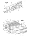
- the heat exchange module shown on the figure 3 is consisting of a radiator 1 for cooling a motor vehicle engine and an air conditioning condenser 2, these two exchangers are generally planar.
- the radiator 1 consists in a known manner of a bundle of fluid circulation tubes 5 mounted between two manifolds 6 (only one box has been shown), the two manifolds 6 being arranged along two parallel sides of the bundle of tubes. tubes and provided with inlet pipes 8 and outlet of the cooling fluid.
- the condenser 2 also consists of a bundle of fluid circulation tubes 10 mounted between two manifolds 12 (only one box has been shown), the manifolds being arranged along two parallel sides of the bundle and provided with tubes of inlet and outlet of the refrigerant (not shown).
- the tubes of each of the exchangers are, for example, aluminum.
- said module also comprises fins as described above, said first and second elements 64,66 of said fins, provided separated from each other, being respectively associated with the tubes 5,10 of the first and second second exchanger.
- the fins of the heat exchange module are constituted by interleaved corrugated sheets disposed between the tubes 5 and the tubes 10 '
- the manifold 6 of the exchanger 1 is formed from metal sheets, preferably aluminum, shaped by conventional cutting and stamping operations.
- the manifold 6 further comprises side flanks 36 folded vis-à-vis which are generally planar and parallel to each other.
- the flanks 36 are connected substantially perpendicular to the bottom by two fold lines which are parallel to each other.
- the tubing 8 is arranged in one of the lateral flanks 36.
- the manifold 6 is closed by a metal strip of given width which has parallel generatrices. This strip can be fitted between the lateral flanks 36 of the manifold 6 to form an assembly ready to be soldered together with the tubing 8.
- the manifold 12 of the exchanger 2 has the general shape of an elongate cylinder provided with perforations for receiving the tubes 10 of the exchanger.
- said heat exchange module according to the invention further comprises at least one cheek 40 joined by soldering to the first heat exchange zone 18 and the second heat exchange zone 20.
- Said cheek is constituted, for example, by a metal plate 37 of generally rectangular shape.
- the tubes 5, 10 of the exchangers are offset from each other in a direction orthogonal to said tubes and the cheeks 40 have an offset 39 of equivalent level between the first and the second exchanger 1,2.
- the module comprises side cheeks 46 deformable.
- said cheeks comprise two portions 48,50 connected to each other by deformable connections 52 and brazed together respectively to the first 18 and the second 20 heat exchange zones.
- the flange 46 comprises two adjacent elongated parts, namely a portion 48 and a portion 50 interconnected by the deformable bonds 52.
- the portion 48 is adapted to be assembled to the first heat exchange zone 18, c that is to say the interleaves of the exchanger 1, while the portion 50 is adapted to be assembled to the second heat exchange zone 20, that is to say the spacers of the exchanger 2.
- One of the parts 50 of the cheek assembled at one of the heat exchange zones 20 comprises at least one protrusion 68 brazed to the other heat exchange zone 18.
- the invention also relates to a method for manufacturing a heat exchange module comprising at least two heat exchangers 1,2, each exchanger comprising generally flat and regularly spaced fluid circulation tubes 5, 10 having a width , and cooling elements 64,66 associated with these tubes 5, 10.
- said sheet metal strip constitutes, for example, a fin as defined above.
- the sheet metal strips 30 are conformed so as to give them a corrugated shape, the association of the sheet metal strips 30 to the tubes of the heat exchangers being done by introduction of the sheet metal strips between the tubes 5, 10.
- the heat exchange zone 18 and the heat exchange zone 20 are still interconnected by the sheet tongues 34.
- the residual links 34 can be broken by moving the exchangers 1,2 relative to one another. More precisely, the separation of the heat exchange zones 18 and 20 can be achieved by a shearing movement exerting on the first exchanger a force in a first direction F1 and on the second exchanger a force in a second direction F2, parallel and opposite to F1 direction.
- Such an operation may be performed by a tool comprising a pair of jaws.41 and 42 adapted to grip the heat exchange zone 18 (tubes 5 and heat exchange elements 64) of the heat exchanger 1, and another pair of jaws 43 and 44 adapted to grip the heat exchange zone 20 (tubes 10 and heat exchange elements 66) of the heat exchanger 2, said pairs of jaws being able to move according to the F1, F2 directions.
- the said residual connection 34 is made, for example by producing a discontinuous slot in the sheet metal strips 30 during their conformation in undulated form.
- cheeks having an offset 39.
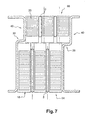
- One of the cheeks may then be positioned in abutment against the heat exchange zone 18 of one of the exchangers 1 and the other cheek 40 bears against the heat exchange zone 20 of the other exchanger 2 when the tubes 5, 10 and the metal strips 30 are combined, as is more particularly illustrated in FIG. figure 6 .
- the said cheeks are then acted in two opposite directions, thereby obtaining the desired offset for the tubes and the breaking of the residual connection between the heat exchange zones.
- the cheeks 40 are then in abutment against the heat exchange elements 64, 66 over their entire width, as illustrated in FIG. figure 7 .
- it may be a cheek deformable such as that described in figure 5 .
- the deformable connections 52 may have been previously obtained through cuts 54 made in the thickness of the metal sheet.
- the two parts 48 and 50 of the cheek are then assembled in abutment against the fins 30 before breaking the residual bonding zones of the heat exchange zones 18,20.
- the flange 46 is associated at the same time as the rest of the exchanger (tubes and fins) and absorbs, 1 thanks to its deformable bonds 52, the shearing movement produced by the separation of the two zones. heat exchange.
- the invention is not limited to the embodiments described above by way of example and extends to other variants.
- plastic manifolds each associated with a metal collector.
- a heat exchange module comprising two heat exchangers 1 and 2 (for example a cooling radiator and a condenser) intended to be traversed by different fluids.
- thermoelectric module which can also be called.
- multi-temperature exchanger in which the exchangers 1 and 2 are traversed by the same fluid, provided at two different temperatures from one exchanger to another.
- the invention finds particular application in the production of heat exchange modules for motor vehicles.
Landscapes
- Engineering & Computer Science (AREA)
- Physics & Mathematics (AREA)
- Mechanical Engineering (AREA)
- Thermal Sciences (AREA)
- General Engineering & Computer Science (AREA)
- Geometry (AREA)
- Heat-Exchange Devices With Radiators And Conduit Assemblies (AREA)
- Details Of Heat-Exchange And Heat-Transfer (AREA)
- Cooling Or The Like Of Semiconductors Or Solid State Devices (AREA)
- Encapsulation Of And Coatings For Semiconductor Or Solid State Devices (AREA)
Claims (13)
- Wärmetauschermodul, das mindestens einen ersten und einen zweiten Wärmetauscher (1, 2) enthält, wobei jeder Tauscher allgemein flache Fluidkreislaufrohre (5, 10) mit gleichmäßigem Abstand, die eine Breite haben, und Wärmetauscherlamellen, insbesondere Kühllamellen, enthält, die aus einem Band (30) bestehen, das eine erste Wärmetauscherzone (18), die dazu bestimmt ist, mit den Rohren des ersten Wärmetauschers zusammenzuwirken, und eine zweite Wärmetauscherzone (20) enthält, die dazu bestimmt ist, mit den Rohren des zweiten Wärmetauschers zusammenzuwirken, wobei das Modul außerdem mindestens eine Seitenwange (40, 46) enthält, die durch Löten an die erste Wärmetauscherzone (18) und an die zweite Wärmetauscherzone (20) montiert wird, dadurch gekennzeichnet, dass das Band vor der Montage eine Schwächungszone (22) enthält, die seine Aufteilung in ein erstes Element (64), das die erste Wärmetauscherzone (18) enthält, und ein zweites Element (66) ermöglicht, das die zweite Wärmetauscherzone (20) enthält, und nach der Montage die ersten und zweiten Elemente (64, 66) der Lamellen, die getrennt voneinander vorgesehen sind, den Rohren (5, 10) des ersten bzw. zweiten Tauschers zugeordnet werden.
- Modul nach Anspruch 1, bei dem das Band (30) eine gewellte Form hat und die Schwächungszone aus einem geradlinigen Schlitz besteht, der in Höhe bestimmter der Seiten der Wellenformen durch mindestens eine Restverbindung (34) unterbrochen ist, die zwischen der ersten und der zweiten Wärmetauscherzone vorgesehen ist.
- Modul nach Anspruch 2, bei dem die Seiten der Wellenformen eine Höhe H haben und die auf halber Höhe vorgesehene Restverbindung eine Höhe h zwischen H/5 und H/30 hat.
- Modul nach Anspruch 2, bei dem der Schlitz aus einem einfachen Ausschnitt ohne Materialentnahme resultiert.
- Wärmetauschermodul nach einem der vorhergehenden Ansprüche, bei dem die Rohre (5, 10) der Tauscher zueinander gemäß einer zu den Rohren orthogonalen Richtung versetzt sind und die Seitenwangen (40) einen entsprechenden Höhenversatz zwischen dem ersten und dem zweiten Tauscher (1, 2) haben.
- Wärmetauschermodul nach einem der vorhergehenden Ansprüche, bei dem die Seitenwangen (46) zwei Teile (48; 50) enthalten, die miteinander über verformbare Verbindungen (52) verbunden sind und durch Löten an die erste (18) bzw. zweite (20) Wärmetauscherzone montiert werden.
- Wärmetauschermodul nach Anspruch 6, bei dem einer der Teile (50) der an eine der Wärmetauscherzonen (20) montierten Seitenwange mindestens einen Vorsprung (68) enthält, der durch Löten an der anderen Wärmetauscherzone (18) befestigt wird.
- Wärmetauschermodul nach einem der vorhergehenden Ansprüche, bei dem der erste Tauscher ein Radiator und der zweite Tauscher ein Kondensator ist.
- Verfahren zur Herstellung eines Moduls nach einem der vorhergehenden Ansprüche, dadurch gekennzeichnet, dass:- die Blechbänder (30) vorgesehen werden,- eine Schwächung (22) der Blechbänder (30) hergestellt wird, um die erste Wärmetauscherzone (18), die dazu bestimmt ist, den Rohren des ersten Tauschers (5) zugeordnet zu werden, und die zweite Wärmetauscherzone (20), die dazu bestimmt ist, den Rohren (10) des zweiten Wärmetauschers (2) zugeordnet zu werden, zu begrenzen, wobei diese Schwächung eine Restverbindung (34) zwischen der ersten Wärmetauscherzone (18) und der zweiten Wärmetauscherzone (20) bestehen lässt,- die Blechbänder (30) den Rohren (5 und 10) der Tauscher (1, 2) zugeordnet werden,- die Restverbindungen (34) zwischen der ersten Wärmetauscherzone (18) und der zweiten Wärmetauscherzone (20) zerbrochen werden, um sie vollständig zu trennen,- die Tauscher (1, 2) durch Löten montiert werden,- eine den zwei Tauschern gemeinsame Seitenwange (40, 46) gegenüber der ersten (18) und der zweiten (20) Wärmetauscherzone angeordnet wird, und- die Tauscher (1, 2) beim Löten durch die Seitenwange aneinander montiert werden.
- Verfahren nach Anspruch 9, bei dem der Vorgang des Zerbrechens der Restverbindungen beim Vorgang der Zuordnung der Blechbänder zu den Rohren durchgeführt wird.
- Verfahren nach einem der Ansprüche 9 oder 10, bei dem die Blechbänder (30) so geformt werden, dass ihnen eine Wellenform verliehen wird, wobei die Zuordnung der Blechbänder (30) zu den Rohren der Wärmetauscher durch Einführen der Blechbänder zwischen die Rohre (5, 10) erfolgt.
- Verfahren nach Anspruch 11, bei dem die Restverbindung hergestellt wird, indem ein unterbrochener Schlitz in den Blechbändern (30) bei ihrer Gestaltung in Wellenform hergestellt wird.
- Verfahren nach einem der Ansprüche 9 bis 12, bei dem die Restverbindungen (34) durch Verschieben der Tauscher (1, 2) zueinander zerbrochen werden.
Applications Claiming Priority (3)
| Application Number | Priority Date | Filing Date | Title |
|---|---|---|---|
| FR0216740A FR2849174B1 (fr) | 2002-12-23 | 2002-12-23 | Ailette d'echange de chaleur, notamment de refroidissement, module d'echange de chaleur comprenant une telle ailette et procede de fabrication d'echangeurs de chaleur utilisant ladite ailette |
| FR0216740 | 2002-12-23 | ||
| PCT/FR2003/003750 WO2004065872A1 (fr) | 2002-12-23 | 2003-12-16 | Procede de fabrication d’un module d’echange de chaleur |
Publications (2)
| Publication Number | Publication Date |
|---|---|
| EP1579162A1 EP1579162A1 (de) | 2005-09-28 |
| EP1579162B1 true EP1579162B1 (de) | 2009-11-04 |
Family
ID=32406537
Family Applications (1)
| Application Number | Title | Priority Date | Filing Date |
|---|---|---|---|
| EP03815413A Expired - Lifetime EP1579162B1 (de) | 2002-12-23 | 2003-12-16 | Wärmetauschermodul und verfahren zur herstellung |
Country Status (8)
| Country | Link |
|---|---|
| US (1) | US7905277B2 (de) |
| EP (1) | EP1579162B1 (de) |
| JP (1) | JP4459062B2 (de) |
| AT (1) | ATE447692T1 (de) |
| AU (1) | AU2003300631A1 (de) |
| DE (1) | DE60329940D1 (de) |
| FR (1) | FR2849174B1 (de) |
| WO (1) | WO2004065872A1 (de) |
Families Citing this family (10)
| Publication number | Priority date | Publication date | Assignee | Title |
|---|---|---|---|---|
| JP4683987B2 (ja) | 2005-04-14 | 2011-05-18 | カルソニックカンセイ株式会社 | 一体型熱交換器のフィン構造 |
| DE102011082797A1 (de) * | 2011-09-15 | 2013-03-21 | Behr Gmbh & Co. Kg | Wärmeübertrager zum Kühlen von Ladeluft |
| FR2987673B1 (fr) * | 2012-03-01 | 2018-06-15 | Valeo Systemes Thermiques | Procede de fabrication d'un tube d'echangeur de chaleur pour vehicule, notamment automobile, tube obtenu par ledit procede et echangeur de chaleur comprenant un tel tube |
| US10281221B2 (en) | 2012-07-18 | 2019-05-07 | Fab Tek Logic, Llc | Removable heatsink fin assembly |
| US9605909B2 (en) | 2012-07-18 | 2017-03-28 | Fab Tek Logic, Llc | Removable radiator fin assembly |
| WO2014149389A1 (en) * | 2013-03-15 | 2014-09-25 | Carrier Corporation | Heat exchanger for air-cooled chiller |
| EP2969612A1 (de) * | 2013-03-15 | 2016-01-20 | Clark Equipment Company | Einzelwärmetauscher-hlk-einheit und leistungsmaschinen damit |
| JP6687967B2 (ja) | 2014-03-24 | 2020-04-28 | 株式会社デンソー | 熱交換器 |
| CN107218822B (zh) * | 2016-03-21 | 2019-04-19 | 丹佛斯微通道换热器(嘉兴)有限公司 | 换热器和空调系统 |
| FR3090837B1 (fr) * | 2018-12-19 | 2021-01-15 | Valeo Systemes Thermiques | Échangeur de chaleur avec joue d’extrémité brasée |
Family Cites Families (16)
| Publication number | Priority date | Publication date | Assignee | Title |
|---|---|---|---|---|
| US4173998A (en) * | 1978-02-16 | 1979-11-13 | Carrier Corporation | Formed coil assembly |
| IE58157B1 (en) * | 1984-10-02 | 1993-07-28 | Badsey Ltd | Heat exchanger fin array |
| DE4203212A1 (de) * | 1992-02-05 | 1993-10-14 | Behr Gmbh & Co | Verfahren zum Herstellen von Wärmetauschern |
| JP3312986B2 (ja) * | 1994-02-25 | 2002-08-12 | 東芝キヤリア株式会社 | 熱交換器および熱交換器の製造方法 |
| US5992514A (en) * | 1995-11-13 | 1999-11-30 | Denso Corporation | Heat exchanger having several exchanging portions |
| JP4019113B2 (ja) * | 1997-11-13 | 2007-12-12 | 株式会社ティラド | 一体型熱交換器のフィンとその製造方法 |
| US6237676B1 (en) * | 1998-04-28 | 2001-05-29 | Denso Corporation | Heat exchanger for vehicle air conditioner |
| US6328098B1 (en) * | 1998-11-10 | 2001-12-11 | Valeo Inc. | Side member for heat exchanger and heat exchanger incorporating side plate |
| JP4379967B2 (ja) * | 1999-03-30 | 2009-12-09 | 株式会社デンソー | 複式熱交換器 |
| JP4207331B2 (ja) * | 1999-09-29 | 2009-01-14 | 株式会社デンソー | 複式熱交換器 |
| JP4482991B2 (ja) * | 1999-12-14 | 2010-06-16 | 株式会社デンソー | 複式熱交換器 |
| US6561264B2 (en) * | 2000-03-16 | 2003-05-13 | Denso Corporation | Compound heat exhanger having cooling fins introducing different heat exhanging performances within heat exchanging core portion |
| FR2812382B1 (fr) * | 2000-07-25 | 2003-02-07 | Valeo Thermique Moteur Sa | Procede de fabrication d'une ailette d'echangeur de chaleur, ailettes selon le procede et module d'echange comportant ces ailettes |
| JP4041654B2 (ja) * | 2001-01-31 | 2008-01-30 | カルソニックカンセイ株式会社 | 熱交換器のルーバーフィンおよびその熱交換器並びにそのルーバーフィンの組付け方法 |
| US20030075307A1 (en) * | 2001-10-22 | 2003-04-24 | Heatcraft, Inc. | Exchanger of thermal energy with multiple cores and a thermal barrier |
| JP4029000B2 (ja) * | 2002-01-25 | 2008-01-09 | カルソニックカンセイ株式会社 | 一体型熱交換器の製造方法およびその一体型熱交換器 |
-
2002
- 2002-12-23 FR FR0216740A patent/FR2849174B1/fr not_active Expired - Fee Related
-
2003
- 2003-12-16 DE DE60329940T patent/DE60329940D1/de not_active Expired - Lifetime
- 2003-12-16 JP JP2004567011A patent/JP4459062B2/ja not_active Expired - Fee Related
- 2003-12-16 AT AT03815413T patent/ATE447692T1/de not_active IP Right Cessation
- 2003-12-16 US US10/539,991 patent/US7905277B2/en not_active Expired - Fee Related
- 2003-12-16 AU AU2003300631A patent/AU2003300631A1/en not_active Abandoned
- 2003-12-16 WO PCT/FR2003/003750 patent/WO2004065872A1/fr not_active Ceased
- 2003-12-16 EP EP03815413A patent/EP1579162B1/de not_active Expired - Lifetime
Also Published As
| Publication number | Publication date |
|---|---|
| FR2849174B1 (fr) | 2006-01-06 |
| EP1579162A1 (de) | 2005-09-28 |
| WO2004065872A1 (fr) | 2004-08-05 |
| US7905277B2 (en) | 2011-03-15 |
| US20060249277A1 (en) | 2006-11-09 |
| JP2006511785A (ja) | 2006-04-06 |
| JP4459062B2 (ja) | 2010-04-28 |
| DE60329940D1 (de) | 2009-12-17 |
| AU2003300631A1 (en) | 2004-08-13 |
| FR2849174A1 (fr) | 2004-06-25 |
| ATE447692T1 (de) | 2009-11-15 |
Similar Documents
| Publication | Publication Date | Title |
|---|---|---|
| EP1176378B1 (de) | Verfahren zur Herstellung einer Rippe für einen Wärmetauscher, Rippe nach solchem Verfahren und Wärmeaustauschsmodul mit solchen Rippen | |
| EP1192402A2 (de) | Wärmetauscher mit mehrkanalrohren | |
| EP2513585A1 (de) | Wärmetauscher | |
| EP1128149A1 (de) | Wärmeaustauchsmodul, insbesondere für Kraftfahrzeug | |
| WO2009141379A1 (fr) | Echangeur de chaleur a plaques, notamment pour vehicules automobiles | |
| FR2902510A1 (fr) | Plaque laterale pour echangeur de chaleur, procede de fabrication d'un echangeur de chaleur et cet echangeur de chaleur | |
| EP1063486B1 (de) | Plattenwärmetauscher, insbesondere Ölkühler für Kraftfahrzeuge | |
| EP1579162B1 (de) | Wärmetauschermodul und verfahren zur herstellung | |
| EP0776454B1 (de) | Flachrohr für einen wärmetauscher | |
| EP1459030A1 (de) | Kreislaufelement für wärmetauscher, insbesondere für ein kraftfahrzeug, und damit hergestellter wärmetauscher | |
| EP1063487B1 (de) | Plattenwärmetauscher, insbesondere zum Kühlen von Kraftfahrzeugöl | |
| EP1174673B1 (de) | Wärmeaustauschsmodul, insbesondere für Kraftfahrzeug, und Verfahren zu dessen Verwendung | |
| WO2005061980A2 (fr) | Element de circuit pour echangeur de chaleur | |
| EP1762808A1 (de) | Kreislaufelement mit Flachrohren und Wärmetauscher mit demselben | |
| EP3645184B1 (de) | Rohr für einen wärmetauscher mit störvorrichtung | |
| EP1285212B2 (de) | Endkammer für einen gelöteten wärmetauscher | |
| FR2904400A1 (fr) | Ensemble de transition entre un echangeur de chaleur et un circuit d'ecoulement exterieur, echangeur de chaleur et procede de fabrication de l'ensemble de transition | |
| WO2002084196A1 (fr) | Faisceau d'echangeur de chaleur comportant une surface d'echange perfectionnee | |
| FR2785978A1 (fr) | Echangeur de chaleur multiple a intercalaires communs | |
| FR2709816A1 (fr) | Echangeur de chaleur brasé utile notamment comme condenseur de climatisation pour véhicule. | |
| EP1063488B1 (de) | Plattenwärmetauscher, insbesondere zum Kühlen von Kraftfahrzeugöl | |
| FR2780153A1 (fr) | Echangeur de chaleur a tubes plats, en particulier pour vehicule automobile | |
| FR2817334A1 (fr) | Echangeur de chaleur brase, notamment pour vehicule automobile, et son procede de fabrication | |
| FR3034184A1 (fr) | Boite collectrice pour echangeur thermique a faisceau de tubes | |
| EP1509740B1 (de) | Verteilerwärmetauscher und verteilerkammer einfacher ausführung, insbesondere für kraftfahrzeug |
Legal Events
| Date | Code | Title | Description |
|---|---|---|---|
| PUAI | Public reference made under article 153(3) epc to a published international application that has entered the european phase |
Free format text: ORIGINAL CODE: 0009012 |
|
| 17P | Request for examination filed |
Effective date: 20050725 |
|
| AK | Designated contracting states |
Kind code of ref document: A1 Designated state(s): AT BE BG CH CY CZ DE DK EE ES FI FR GB GR HU IE IT LI LU MC NL PT RO SE SI SK TR |
|
| AX | Request for extension of the european patent |
Extension state: AL LT LV MK |
|
| DAX | Request for extension of the european patent (deleted) | ||
| RIN1 | Information on inventor provided before grant (corrected) |
Inventor name: SANCHIS, ALEXANDRE Inventor name: BAUHEREHIM, ALAIN Inventor name: LESUEUR, JEAN, MARC Inventor name: TRAVERS, FLORENT Inventor name: RIONDET, CHRISTIAN Inventor name: ARNESEN, JENS, PETTER |
|
| 17Q | First examination report despatched |
Effective date: 20060215 |
|
| RAP1 | Party data changed (applicant data changed or rights of an application transferred) |
Owner name: VALEO SYSTEMES THERMIQUES |
|
| GRAP | Despatch of communication of intention to grant a patent |
Free format text: ORIGINAL CODE: EPIDOSNIGR1 |
|
| RTI1 | Title (correction) |
Free format text: HEAT EXCHANGER MODULE AND METHOD OF PRODUCING |
|
| GRAS | Grant fee paid |
Free format text: ORIGINAL CODE: EPIDOSNIGR3 |
|
| GRAA | (expected) grant |
Free format text: ORIGINAL CODE: 0009210 |
|
| AK | Designated contracting states |
Kind code of ref document: B1 Designated state(s): AT BE BG CH CY CZ DE DK EE ES FI FR GB GR HU IE IT LI LU MC NL PT RO SE SI SK TR |
|
| REG | Reference to a national code |
Ref country code: GB Ref legal event code: FG4D Free format text: NOT ENGLISH |
|
| REG | Reference to a national code |
Ref country code: CH Ref legal event code: EP |
|
| REG | Reference to a national code |
Ref country code: IE Ref legal event code: FG4D |
|
| REF | Corresponds to: |
Ref document number: 60329940 Country of ref document: DE Date of ref document: 20091217 Kind code of ref document: P |
|
| NLV1 | Nl: lapsed or annulled due to failure to fulfill the requirements of art. 29p and 29m of the patents act | ||
| PG25 | Lapsed in a contracting state [announced via postgrant information from national office to epo] |
Ref country code: ES Free format text: LAPSE BECAUSE OF FAILURE TO SUBMIT A TRANSLATION OF THE DESCRIPTION OR TO PAY THE FEE WITHIN THE PRESCRIBED TIME-LIMIT Effective date: 20100215 Ref country code: FI Free format text: LAPSE BECAUSE OF FAILURE TO SUBMIT A TRANSLATION OF THE DESCRIPTION OR TO PAY THE FEE WITHIN THE PRESCRIBED TIME-LIMIT Effective date: 20091104 Ref country code: PT Free format text: LAPSE BECAUSE OF FAILURE TO SUBMIT A TRANSLATION OF THE DESCRIPTION OR TO PAY THE FEE WITHIN THE PRESCRIBED TIME-LIMIT Effective date: 20100304 Ref country code: SE Free format text: LAPSE BECAUSE OF FAILURE TO SUBMIT A TRANSLATION OF THE DESCRIPTION OR TO PAY THE FEE WITHIN THE PRESCRIBED TIME-LIMIT Effective date: 20091104 |
|
| REG | Reference to a national code |
Ref country code: IE Ref legal event code: FD4D |
|
| PG25 | Lapsed in a contracting state [announced via postgrant information from national office to epo] |
Ref country code: SI Free format text: LAPSE BECAUSE OF FAILURE TO SUBMIT A TRANSLATION OF THE DESCRIPTION OR TO PAY THE FEE WITHIN THE PRESCRIBED TIME-LIMIT Effective date: 20091104 Ref country code: CY Free format text: LAPSE BECAUSE OF FAILURE TO SUBMIT A TRANSLATION OF THE DESCRIPTION OR TO PAY THE FEE WITHIN THE PRESCRIBED TIME-LIMIT Effective date: 20091104 |
|
| BERE | Be: lapsed |
Owner name: VALEO SYSTEMES THERMIQUES Effective date: 20091231 |
|
| PG25 | Lapsed in a contracting state [announced via postgrant information from national office to epo] |
Ref country code: AT Free format text: LAPSE BECAUSE OF FAILURE TO SUBMIT A TRANSLATION OF THE DESCRIPTION OR TO PAY THE FEE WITHIN THE PRESCRIBED TIME-LIMIT Effective date: 20091104 |
|
| PG25 | Lapsed in a contracting state [announced via postgrant information from national office to epo] |
Ref country code: EE Free format text: LAPSE BECAUSE OF FAILURE TO SUBMIT A TRANSLATION OF THE DESCRIPTION OR TO PAY THE FEE WITHIN THE PRESCRIBED TIME-LIMIT Effective date: 20091104 Ref country code: RO Free format text: LAPSE BECAUSE OF FAILURE TO SUBMIT A TRANSLATION OF THE DESCRIPTION OR TO PAY THE FEE WITHIN THE PRESCRIBED TIME-LIMIT Effective date: 20091104 Ref country code: MC Free format text: LAPSE BECAUSE OF NON-PAYMENT OF DUE FEES Effective date: 20100701 Ref country code: DK Free format text: LAPSE BECAUSE OF FAILURE TO SUBMIT A TRANSLATION OF THE DESCRIPTION OR TO PAY THE FEE WITHIN THE PRESCRIBED TIME-LIMIT Effective date: 20091104 Ref country code: IE Free format text: LAPSE BECAUSE OF FAILURE TO SUBMIT A TRANSLATION OF THE DESCRIPTION OR TO PAY THE FEE WITHIN THE PRESCRIBED TIME-LIMIT Effective date: 20091104 Ref country code: BG Free format text: LAPSE BECAUSE OF FAILURE TO SUBMIT A TRANSLATION OF THE DESCRIPTION OR TO PAY THE FEE WITHIN THE PRESCRIBED TIME-LIMIT Effective date: 20100204 |
|
| REG | Reference to a national code |
Ref country code: CH Ref legal event code: PL |
|
| PG25 | Lapsed in a contracting state [announced via postgrant information from national office to epo] |
Ref country code: SK Free format text: LAPSE BECAUSE OF FAILURE TO SUBMIT A TRANSLATION OF THE DESCRIPTION OR TO PAY THE FEE WITHIN THE PRESCRIBED TIME-LIMIT Effective date: 20091104 Ref country code: CZ Free format text: LAPSE BECAUSE OF FAILURE TO SUBMIT A TRANSLATION OF THE DESCRIPTION OR TO PAY THE FEE WITHIN THE PRESCRIBED TIME-LIMIT Effective date: 20091104 |
|
| PLBE | No opposition filed within time limit |
Free format text: ORIGINAL CODE: 0009261 |
|
| STAA | Information on the status of an ep patent application or granted ep patent |
Free format text: STATUS: NO OPPOSITION FILED WITHIN TIME LIMIT |
|
| 26N | No opposition filed |
Effective date: 20100805 |
|
| PG25 | Lapsed in a contracting state [announced via postgrant information from national office to epo] |
Ref country code: LI Free format text: LAPSE BECAUSE OF NON-PAYMENT OF DUE FEES Effective date: 20091231 Ref country code: GR Free format text: LAPSE BECAUSE OF FAILURE TO SUBMIT A TRANSLATION OF THE DESCRIPTION OR TO PAY THE FEE WITHIN THE PRESCRIBED TIME-LIMIT Effective date: 20100205 Ref country code: CH Free format text: LAPSE BECAUSE OF NON-PAYMENT OF DUE FEES Effective date: 20091231 Ref country code: BE Free format text: LAPSE BECAUSE OF NON-PAYMENT OF DUE FEES Effective date: 20091231 |
|
| PG25 | Lapsed in a contracting state [announced via postgrant information from national office to epo] |
Ref country code: IT Free format text: LAPSE BECAUSE OF FAILURE TO SUBMIT A TRANSLATION OF THE DESCRIPTION OR TO PAY THE FEE WITHIN THE PRESCRIBED TIME-LIMIT Effective date: 20091104 |
|
| PG25 | Lapsed in a contracting state [announced via postgrant information from national office to epo] |
Ref country code: LU Free format text: LAPSE BECAUSE OF NON-PAYMENT OF DUE FEES Effective date: 20091216 |
|
| PG25 | Lapsed in a contracting state [announced via postgrant information from national office to epo] |
Ref country code: HU Free format text: LAPSE BECAUSE OF FAILURE TO SUBMIT A TRANSLATION OF THE DESCRIPTION OR TO PAY THE FEE WITHIN THE PRESCRIBED TIME-LIMIT Effective date: 20100505 |
|
| PG25 | Lapsed in a contracting state [announced via postgrant information from national office to epo] |
Ref country code: TR Free format text: LAPSE BECAUSE OF FAILURE TO SUBMIT A TRANSLATION OF THE DESCRIPTION OR TO PAY THE FEE WITHIN THE PRESCRIBED TIME-LIMIT Effective date: 20091104 |
|
| PG25 | Lapsed in a contracting state [announced via postgrant information from national office to epo] |
Ref country code: NL Free format text: LAPSE BECAUSE OF FAILURE TO SUBMIT A TRANSLATION OF THE DESCRIPTION OR TO PAY THE FEE WITHIN THE PRESCRIBED TIME-LIMIT Effective date: 20091104 |
|
| REG | Reference to a national code |
Ref country code: FR Ref legal event code: PLFP Year of fee payment: 13 |
|
| REG | Reference to a national code |
Ref country code: FR Ref legal event code: PLFP Year of fee payment: 14 |
|
| PGFP | Annual fee paid to national office [announced via postgrant information from national office to epo] |
Ref country code: GB Payment date: 20161221 Year of fee payment: 14 |
|
| PGFP | Annual fee paid to national office [announced via postgrant information from national office to epo] |
Ref country code: FR Payment date: 20161229 Year of fee payment: 14 |
|
| PGFP | Annual fee paid to national office [announced via postgrant information from national office to epo] |
Ref country code: DE Payment date: 20161221 Year of fee payment: 14 |
|
| REG | Reference to a national code |
Ref country code: DE Ref legal event code: R119 Ref document number: 60329940 Country of ref document: DE |
|
| GBPC | Gb: european patent ceased through non-payment of renewal fee |
Effective date: 20171216 |
|
| REG | Reference to a national code |
Ref country code: FR Ref legal event code: ST Effective date: 20180831 |
|
| PG25 | Lapsed in a contracting state [announced via postgrant information from national office to epo] |
Ref country code: FR Free format text: LAPSE BECAUSE OF NON-PAYMENT OF DUE FEES Effective date: 20180102 Ref country code: DE Free format text: LAPSE BECAUSE OF NON-PAYMENT OF DUE FEES Effective date: 20180703 |
|
| PG25 | Lapsed in a contracting state [announced via postgrant information from national office to epo] |
Ref country code: GB Free format text: LAPSE BECAUSE OF NON-PAYMENT OF DUE FEES Effective date: 20171216 |