JP6687967B2 - Heat exchanger - Google Patents
Heat exchanger Download PDFInfo
- Publication number
- JP6687967B2 JP6687967B2 JP2014059756A JP2014059756A JP6687967B2 JP 6687967 B2 JP6687967 B2 JP 6687967B2 JP 2014059756 A JP2014059756 A JP 2014059756A JP 2014059756 A JP2014059756 A JP 2014059756A JP 6687967 B2 JP6687967 B2 JP 6687967B2
- Authority
- JP
- Japan
- Prior art keywords
- fin
- tube
- fluid
- flow direction
- flat
- Prior art date
- Legal status (The legal status is an assumption and is not a legal conclusion. Google has not performed a legal analysis and makes no representation as to the accuracy of the status listed.)
- Expired - Fee Related
Links
- 230000008014 freezing Effects 0.000 claims description 68
- 238000007710 freezing Methods 0.000 claims description 68
- 239000012530 fluid Substances 0.000 claims description 52
- 238000011144 upstream manufacturing Methods 0.000 claims description 39
- XLYOFNOQVPJJNP-UHFFFAOYSA-N water Substances O XLYOFNOQVPJJNP-UHFFFAOYSA-N 0.000 claims description 36
- 239000011800 void material Substances 0.000 claims description 21
- 238000005520 cutting process Methods 0.000 claims description 6
- 239000000126 substance Substances 0.000 claims description 4
- 239000003507 refrigerant Substances 0.000 description 17
- 230000000694 effects Effects 0.000 description 6
- 239000011232 storage material Substances 0.000 description 6
- 238000005336 cracking Methods 0.000 description 4
- 239000007788 liquid Substances 0.000 description 3
- 230000012447 hatching Effects 0.000 description 2
- 239000000463 material Substances 0.000 description 2
- 230000002093 peripheral effect Effects 0.000 description 2
- 238000003860 storage Methods 0.000 description 2
- 229910000838 Al alloy Inorganic materials 0.000 description 1
- 230000002528 anti-freeze Effects 0.000 description 1
- 238000005219 brazing Methods 0.000 description 1
- 238000001125 extrusion Methods 0.000 description 1
- 230000005484 gravity Effects 0.000 description 1
- 238000010030 laminating Methods 0.000 description 1
- 239000000155 melt Substances 0.000 description 1
- 229910052751 metal Inorganic materials 0.000 description 1
- 239000002184 metal Substances 0.000 description 1
- 239000007769 metal material Substances 0.000 description 1
- 238000000034 method Methods 0.000 description 1
- 238000005192 partition Methods 0.000 description 1
- 238000005057 refrigeration Methods 0.000 description 1
- 230000003014 reinforcing effect Effects 0.000 description 1
- 230000000630 rising effect Effects 0.000 description 1
Images


Classifications
-
- F—MECHANICAL ENGINEERING; LIGHTING; HEATING; WEAPONS; BLASTING
- F28—HEAT EXCHANGE IN GENERAL
- F28F—DETAILS OF HEAT-EXCHANGE AND HEAT-TRANSFER APPARATUS, OF GENERAL APPLICATION
- F28F1/00—Tubular elements; Assemblies of tubular elements
- F28F1/10—Tubular elements and assemblies thereof with means for increasing heat-transfer area, e.g. with fins, with projections, with recesses
- F28F1/12—Tubular elements and assemblies thereof with means for increasing heat-transfer area, e.g. with fins, with projections, with recesses the means being only outside the tubular element
- F28F1/126—Tubular elements and assemblies thereof with means for increasing heat-transfer area, e.g. with fins, with projections, with recesses the means being only outside the tubular element consisting of zig-zag shaped fins
- F28F1/128—Fins with openings, e.g. louvered fins
-
- B—PERFORMING OPERATIONS; TRANSPORTING
- B60—VEHICLES IN GENERAL
- B60H—ARRANGEMENTS OF HEATING, COOLING, VENTILATING OR OTHER AIR-TREATING DEVICES SPECIALLY ADAPTED FOR PASSENGER OR GOODS SPACES OF VEHICLES
- B60H1/00—Heating, cooling or ventilating [HVAC] devices
- B60H1/32—Cooling devices
-
- F—MECHANICAL ENGINEERING; LIGHTING; HEATING; WEAPONS; BLASTING
- F28—HEAT EXCHANGE IN GENERAL
- F28D—HEAT-EXCHANGE APPARATUS, NOT PROVIDED FOR IN ANOTHER SUBCLASS, IN WHICH THE HEAT-EXCHANGE MEDIA DO NOT COME INTO DIRECT CONTACT
- F28D1/00—Heat-exchange apparatus having stationary conduit assemblies for one heat-exchange medium only, the media being in contact with different sides of the conduit wall, in which the other heat-exchange medium is a large body of fluid, e.g. domestic or motor car radiators
- F28D1/02—Heat-exchange apparatus having stationary conduit assemblies for one heat-exchange medium only, the media being in contact with different sides of the conduit wall, in which the other heat-exchange medium is a large body of fluid, e.g. domestic or motor car radiators with heat-exchange conduits immersed in the body of fluid
- F28D1/04—Heat-exchange apparatus having stationary conduit assemblies for one heat-exchange medium only, the media being in contact with different sides of the conduit wall, in which the other heat-exchange medium is a large body of fluid, e.g. domestic or motor car radiators with heat-exchange conduits immersed in the body of fluid with tubular conduits
- F28D1/053—Heat-exchange apparatus having stationary conduit assemblies for one heat-exchange medium only, the media being in contact with different sides of the conduit wall, in which the other heat-exchange medium is a large body of fluid, e.g. domestic or motor car radiators with heat-exchange conduits immersed in the body of fluid with tubular conduits the conduits being straight
- F28D1/0535—Heat-exchange apparatus having stationary conduit assemblies for one heat-exchange medium only, the media being in contact with different sides of the conduit wall, in which the other heat-exchange medium is a large body of fluid, e.g. domestic or motor car radiators with heat-exchange conduits immersed in the body of fluid with tubular conduits the conduits being straight the conduits having a non-circular cross-section
- F28D1/05366—Assemblies of conduits connected to common headers, e.g. core type radiators
- F28D1/05383—Assemblies of conduits connected to common headers, e.g. core type radiators with multiple rows of conduits or with multi-channel conduits
-
- F—MECHANICAL ENGINEERING; LIGHTING; HEATING; WEAPONS; BLASTING
- F28—HEAT EXCHANGE IN GENERAL
- F28D—HEAT-EXCHANGE APPARATUS, NOT PROVIDED FOR IN ANOTHER SUBCLASS, IN WHICH THE HEAT-EXCHANGE MEDIA DO NOT COME INTO DIRECT CONTACT
- F28D20/00—Heat storage plants or apparatus in general; Regenerative heat-exchange apparatus not covered by groups F28D17/00 or F28D19/00
- F28D20/02—Heat storage plants or apparatus in general; Regenerative heat-exchange apparatus not covered by groups F28D17/00 or F28D19/00 using latent heat
-
- F—MECHANICAL ENGINEERING; LIGHTING; HEATING; WEAPONS; BLASTING
- F28—HEAT EXCHANGE IN GENERAL
- F28F—DETAILS OF HEAT-EXCHANGE AND HEAT-TRANSFER APPARATUS, OF GENERAL APPLICATION
- F28F1/00—Tubular elements; Assemblies of tubular elements
- F28F1/10—Tubular elements and assemblies thereof with means for increasing heat-transfer area, e.g. with fins, with projections, with recesses
- F28F1/12—Tubular elements and assemblies thereof with means for increasing heat-transfer area, e.g. with fins, with projections, with recesses the means being only outside the tubular element
- F28F1/24—Tubular elements and assemblies thereof with means for increasing heat-transfer area, e.g. with fins, with projections, with recesses the means being only outside the tubular element and extending transversely
- F28F1/30—Tubular elements and assemblies thereof with means for increasing heat-transfer area, e.g. with fins, with projections, with recesses the means being only outside the tubular element and extending transversely the means being attachable to the element
-
- F—MECHANICAL ENGINEERING; LIGHTING; HEATING; WEAPONS; BLASTING
- F28—HEAT EXCHANGE IN GENERAL
- F28D—HEAT-EXCHANGE APPARATUS, NOT PROVIDED FOR IN ANOTHER SUBCLASS, IN WHICH THE HEAT-EXCHANGE MEDIA DO NOT COME INTO DIRECT CONTACT
- F28D20/00—Heat storage plants or apparatus in general; Regenerative heat-exchange apparatus not covered by groups F28D17/00 or F28D19/00
- F28D2020/0004—Particular heat storage apparatus
- F28D2020/0013—Particular heat storage apparatus the heat storage material being enclosed in elements attached to or integral with heat exchange conduits
-
- F—MECHANICAL ENGINEERING; LIGHTING; HEATING; WEAPONS; BLASTING
- F28—HEAT EXCHANGE IN GENERAL
- F28D—HEAT-EXCHANGE APPARATUS, NOT PROVIDED FOR IN ANOTHER SUBCLASS, IN WHICH THE HEAT-EXCHANGE MEDIA DO NOT COME INTO DIRECT CONTACT
- F28D21/00—Heat-exchange apparatus not covered by any of the groups F28D1/00 - F28D20/00
- F28D2021/0019—Other heat exchangers for particular applications; Heat exchange systems not otherwise provided for
- F28D2021/008—Other heat exchangers for particular applications; Heat exchange systems not otherwise provided for for vehicles
- F28D2021/0085—Evaporators
-
- F—MECHANICAL ENGINEERING; LIGHTING; HEATING; WEAPONS; BLASTING
- F28—HEAT EXCHANGE IN GENERAL
- F28F—DETAILS OF HEAT-EXCHANGE AND HEAT-TRANSFER APPARATUS, OF GENERAL APPLICATION
- F28F2215/00—Fins
- F28F2215/04—Assemblies of fins having different features, e.g. with different fin densities
-
- F—MECHANICAL ENGINEERING; LIGHTING; HEATING; WEAPONS; BLASTING
- F28—HEAT EXCHANGE IN GENERAL
- F28F—DETAILS OF HEAT-EXCHANGE AND HEAT-TRANSFER APPARATUS, OF GENERAL APPLICATION
- F28F2240/00—Spacing means
-
- F—MECHANICAL ENGINEERING; LIGHTING; HEATING; WEAPONS; BLASTING
- F28—HEAT EXCHANGE IN GENERAL
- F28F—DETAILS OF HEAT-EXCHANGE AND HEAT-TRANSFER APPARATUS, OF GENERAL APPLICATION
- F28F2265/00—Safety or protection arrangements; Arrangements for preventing malfunction
- F28F2265/14—Safety or protection arrangements; Arrangements for preventing malfunction for preventing damage by freezing, e.g. for accommodating volume expansion
-
- Y—GENERAL TAGGING OF NEW TECHNOLOGICAL DEVELOPMENTS; GENERAL TAGGING OF CROSS-SECTIONAL TECHNOLOGIES SPANNING OVER SEVERAL SECTIONS OF THE IPC; TECHNICAL SUBJECTS COVERED BY FORMER USPC CROSS-REFERENCE ART COLLECTIONS [XRACs] AND DIGESTS
- Y02—TECHNOLOGIES OR APPLICATIONS FOR MITIGATION OR ADAPTATION AGAINST CLIMATE CHANGE
- Y02E—REDUCTION OF GREENHOUSE GAS [GHG] EMISSIONS, RELATED TO ENERGY GENERATION, TRANSMISSION OR DISTRIBUTION
- Y02E60/00—Enabling technologies; Technologies with a potential or indirect contribution to GHG emissions mitigation
- Y02E60/14—Thermal energy storage
Description
本発明は、表面温度が氷点を下回る可能性がある熱交換器に関するものである。 The present invention relates to a heat exchanger whose surface temperature may be below freezing.
従来、車両空調装置の蒸発器は、冷媒が流通するチューブと、チューブに接合されてチューブ周りを流れる空気と冷媒との熱交換面積を増大させるフィンとを備えている(例えば、特許文献1参照)。 Conventionally, an evaporator of a vehicle air conditioner includes a tube through which a refrigerant flows, and fins that are joined to the tube and increase a heat exchange area between the air flowing around the tube and the refrigerant (for example, see Patent Document 1). ).
このような蒸発器において表面温度が氷点を下回ると、蒸発器の表面に付着した凝縮水が凍結することで体積が膨張して周辺のチューブおよびフィンが破壊されるという凍結割れが発生するおそれがある。 When the surface temperature of such an evaporator falls below the freezing point, the condensed water adhering to the surface of the evaporator freezes and the volume expands, which may cause freezing cracking in which peripheral tubes and fins are destroyed. is there.
これに対し、従来の車両用空調装置では、サーミスタを用いて蒸発器の温度制御を行うことにより、蒸発器温度が基準温度以下になった際に、冷凍サイクルを停止または熱負荷を低下させている。これにより、蒸発器の表面に付着した凝縮水が凍結しない、もしくは凍結割れが発生しない程度までしか凝縮水が凍結しないようにできる。 On the other hand, in the conventional vehicle air conditioner, by controlling the temperature of the evaporator using the thermistor, when the evaporator temperature becomes lower than the reference temperature, the refrigeration cycle is stopped or the heat load is reduced. There is. As a result, the condensed water attached to the surface of the evaporator can be prevented from freezing, or the condensed water can be frozen only to such an extent that freeze cracking does not occur.
しかしながら、近年、ヒートポンプサイクルにおける低圧冷媒を外気と熱交換させて蒸発させる蒸発器として機能する室外熱交換器のように、表面温度が氷点を下回るような環境下で熱交換器を使用するニーズが高まっている。この場合、上述したような蒸発器の温度制御では、凍結割れへの対応が困難となってくる。 However, in recent years, there is a need to use the heat exchanger in an environment where the surface temperature is below the freezing point, such as an outdoor heat exchanger that functions as an evaporator that heat-exchanges low-pressure refrigerant with the outside air in a heat pump cycle. It is rising. In this case, it becomes difficult to deal with freeze cracking by controlling the temperature of the evaporator as described above.
本発明は上記点に鑑みて、表面温度が氷点を下回る可能性がある熱交換器において、凍結割れの発生を抑制することを目的とする。 In view of the above points, the present invention has an object to suppress the occurrence of freeze cracking in a heat exchanger in which the surface temperature may be below the freezing point.
上記目的を達成するため、請求項1に記載の発明では、内部に第1流体が流れる複数本積層されたチューブ(1)と、チューブ(1)に接合されてチューブ(1)周りを流れる第2流体との熱交換面積を増大させるフィン(2)とを備え、フィン(2)における第2流体の流れ方向に垂直な断面形状は、第2流体の流れ方向と略平行な複数の平面部(21)と、隣り合う平面部(21)間を繋ぐ頂部(22)とを有する波形状であり、チューブ(1)およびフィン(2)の少なくとも一方の表面温度が氷点以下になる可能性のある熱交換器において、フィン(2)の平面部(21)には、平面部(21)を切り起こすことによりルーバ(23)が一体形成されており、フィン(2)の平面部(21)のうち第2流体の流れ方向の中央部におけるルーバ(23)が形成されていない部位(26)には、チューブ(1)またはフィン(2)に付着した水または水含有物が凍結する際に最終的に凍結する部位の凍結による体積膨張に伴う負荷を逃がすための空隙部(27、28)が設けられており、チューブ(1)の内部には、第1流体が流れる第1流体通路が形成されており、空隙部(27、28)の少なくとも一部は、チューブ(1)の積層方向から見たときに、第1流体通路と重なるように配置されており、平面部(21)のうち空隙部(27、28)の外縁を構成する部位は、下方側に向けて突出する突出部が接続されていない平面状に形成されており、空隙部(27、28)に対して第2流体の流れ方向上流側および下流側に位置する平面部(21)は、同一のフィン(2)により構成されており、フィン(2)のフィンピッチをFp、空隙部(27、28)における第2流体の流れ方向の長さである空隙部巾をWとしたとき、フィンピッチおよび空隙部巾が、W>0.414×Fp+0.0575の関係を満たしていることを特徴とする。
In order to achieve the above object, in the invention according to
チューブ(1)およびフィン(2)の少なくとも一方の表面温度が氷点以下になる可能性のある熱交換器においては、チューブ(1)またはフィン(2)に付着した凝縮水等の液体(水または水含有物)が凍結する際に、液体の周縁部から凍結が進行して中央部が最終的に凍結する。このため、最終的に凍結が完了する部位(以下、最終凍結部という)が既に凍結が完了している凍結部内に内包されてしまい、凍結による体積膨張に伴い周辺のチューブ(1)やフィン(2)に負荷がかかる。これにより、チューブ(1)やフィン(2)に凍結割れが発生するおそれがある。 In a heat exchanger in which the surface temperature of at least one of the tube (1) and the fin (2) may be lower than the freezing point, liquid (such as condensed water) such as condensed water attached to the tube (1) or the fin (2) When the water-containing material) freezes, the freezing proceeds from the peripheral portion of the liquid and the central portion finally freezes. For this reason, the part where the freezing is finally completed (hereinafter referred to as the final freezing part) is included in the freezing part where the freezing is already completed, and the surrounding tubes (1) and fins ( Load is applied to 2). This may cause freezing cracks in the tubes (1) and fins (2).
これに対し、フィン(2)の平面部(21)に空隙部(27、28)を設けることで、当該空隙部(27、28)において、最終凍結部の凍結による体積膨張に伴う負荷(以下、凍結負荷という)を逃がすことができる。さらに、空隙部(27、28)を、フィン(2)の平面部(21)におけるルーバ(23)が形成されていない部位(24、25、26)に設けることで、フィン(2)のうち凍結負荷が最大となる部位において、凍結負荷を逃がすことができるので、チューブ(1)やフィン(2)に凍結割れが発生することを抑制できる。
また、請求項2に記載の発明では、内部に第1流体が流れる複数本積層されたチューブ(1)と、チューブ(1)に接合されてチューブ(1)周りを流れる第2流体との熱交換面積を増大させるフィン(2)とを備え、フィン(2)における第2流体の流れ方向に垂直な断面形状は、第2流体流れ方向と略平行な複数の平面部(21)と、隣り合う平面部(21)間を繋ぐ頂部(22)とを有する波形状であり、チューブ(1)およびフィン(2)の少なくとも一方の表面温度が氷点以下になる可能性のある熱交換器において、フィン(2)の平面部(21)には、平面部(21)を切り起こすことによりルーバ(23)が一体形成されており、フィン(2)の平面部(21)のうち第2流体の流れ方向の中央部におけるルーバ(23)が形成されていない部位(26)には、チューブ(1)またはフィン(2)に付着した水または水含有物が凍結する際に最終的に凍結する部位の凍結による体積膨張に伴う負荷を逃がすための空隙部(27、28)が設けられており、チューブ(1)の内部には、第1流体が流れる第1流体通路が複数形成されており、チューブ(1)は、複数の第1流体通路を挟んで対向する二つの扁平面(10a、10b)を有しており、空隙部(27、28)の少なくとも一部は、チューブ(1)の積層方向から見たときに、チューブ(1)における複数の第1流体流路のうち少なくとも1つと重なるように配置されており、フィン(2)における、第2流体の流れ方向に対する空隙部(27、28)の上流側および下流側は、チューブ(1)の扁平面(10a、10b)にそれぞれ接合されており、平面部(21)のうち空隙部(27、28)の外縁を構成する部位は、下方側に向けて突出する突出部が接続されていない平面状に形成されており、空隙部(27、28)に対して第2流体の流れ方向上流側および下流側に位置する平面部(21)は、同一のフィン(2)により構成されており、フィン(2)のフィンピッチをFp、空隙部(27、28)における第2流体の流れ方向の長さである空隙部巾をWとしたとき、フィンピッチおよび空隙部巾が、W>0.414×Fp+0.0575の関係を満たしていることを特徴とする。
これによれば、請求項1に記載の発明と同様の効果を得ることができる。
On the other hand, by providing the voids (27, 28) on the flat surface portion (21) of the fin (2), the load (hereinafter , Freezing load). Further, by providing the voids (27, 28) at the portions (24, 25, 26) where the louver (23) is not formed in the flat portion (21) of the fin (2), Since the freezing load can be released at the portion where the freezing load is the maximum, it is possible to suppress the occurrence of freezing cracks in the tube (1) and the fins (2).
Further, in the invention according to
According to this, the same effect as that of the invention described in
なお、この欄および特許請求の範囲で記載した各手段の括弧内の符号は、後述する実施形態に記載の具体的手段との対応関係を示すものである。 It should be noted that the reference numerals in parentheses for each means described in this column and in the claims indicate the correspondence with the specific means described in the embodiments described later.
以下、本発明の実施形態について図に基づいて説明する。以下に説明する実施形態のうち、第1〜第3、第5、第6、第8実施形態が特許請求の範囲に記載した発明の実施形態であり、第4、第7実施形態は、参考例として示す形態である。なお、以下の各実施形態相互において、互いに同一もしくは均等である部分には、図中、同一符号を付してある。 Hereinafter, embodiments of the present invention will be described with reference to the drawings. Of the embodiments described below, the first to third, fifth, sixth, and eighth embodiments are embodiments of the invention described in the claims, and the fourth and seventh embodiments are for reference. It is a form shown as an example. In the following respective embodiments, the same or equivalent parts are designated by the same reference numerals in the drawings.
(第1実施形態)
本発明の第1実施形態について図1〜図11に基づいて説明する。本実施形態は、本発明に係る熱交換器を、ヒートポンプサイクルにおける低圧冷媒を外気と熱交換させて蒸発させる蒸発器として機能する室外熱交換器に適用したものである。
(First embodiment)
1st Embodiment of this invention is described based on FIGS. The present embodiment is an application of the heat exchanger according to the present invention to an outdoor heat exchanger that functions as an evaporator that heat-exchanges low-pressure refrigerant with outside air in a heat pump cycle to evaporate it.
図1に示すように、室外熱交換器は、内部流体としての冷媒が鉛直方向に流れるダウンフロー型の熱交換器である。室外熱交換器は、冷媒が流れる管であるチューブ1を備えている。
As shown in FIG. 1, the outdoor heat exchanger is a downflow type heat exchanger in which a refrigerant as an internal fluid flows in a vertical direction. The outdoor heat exchanger includes a
チューブ1は、外部流体としての空気の流れ方向(以下、空気流れ方向X1という)が長径方向と一致するように、長手方向垂直断面の形状が扁平な長円形状(扁平形状)に形成されている。チューブ1は、その長手方向が鉛直方向に一致するように水平方向に複数本平行に配置されている。なお、本実施形態では、チューブ1として、押出加工による微細多穴チューブを採用している。
The
また、チューブ1は、チューブ1における冷媒が流通する流体通路を挟んで対向する二つの扁平面10a、10bを有している。チューブ1の両側の扁平面10a、10bには、波状に成形された伝熱部材としてのフィン2が接合されている。このフィン2により空気との伝熱面積を増大させて冷媒と空気との熱交換を促進している。このため、チューブ1は、本発明の熱交換対象物に相当している。なお、以下、チューブ1およびフィン2からなる略矩形状の熱交換部をコア部3と呼ぶ。
In addition, the
ヘッダタンク4は、チューブ1の長手方向(以下、チューブ長手方向X2という)の端部(本実施形態では、上下端)にてチューブ長手方向X2と直交する方向(本実施形態では、水平方向)に延びて複数のチューブ1と連通するものである。ヘッダタンク4は、チューブ1が挿入接合されたコアプレート4aと、コアプレート4aとともにタンク内空間を構成するタンク本体部4bとを有して構成されている。本実施形態では、コアプレート4aおよびタンク本体部4bは、金属(例えば、アルミニウム合金)製である。また、コア部3の両端部には、チューブ長手方向X2と略平行に延びてコア部3を補強するインサート5が設けられている。
The
二つのヘッダタンク4のうち、上方側に配置されるとともに、チューブ1に冷媒を分流する入口側タンク41のタンク本体部4bには、冷媒をタンク本体部4b内に流入させる入口パイプ4cが設けられている。また、二つのヘッダタンク4のうち、下方側に配置されるとともに、チューブ1から流出する冷媒を集合する出口側タンク42のタンク本体部4bには、空気との熱交換により冷却された冷媒を流出させる出口パイプ4dが設けられている。
Of the two
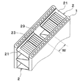
図2に示すように、フィン2は、板状の板部21、および隣り合う板部21を所定距離離して位置づける頂部22を有するように波状に形成されたコルゲートフィンである。板部21は、空気流れ方向X1に沿って広がる面を提供している。板部21は、平板によって提供されることができ、以下の説明では、平面部21とも称される。
As shown in FIG. 2, the
頂部22は、狭い巾の平面を外側に面するように提供する平板状の頂板部を有する。頂板部と平面部21との間には、ほぼ直角の曲げ部が設けられている。頂板部は、チューブ1に接合され、フィン2とチューブ1とが熱伝達可能に接合される。頂部22は、その頂板部の巾が充分に狭く形成され、曲げ部が大きな半径をもって形成されると、全体として湾曲した湾曲部として見ることができる。よって、以下の説明では、頂部22は湾曲部22とも称される。
The
この波状のフィン2は本実施形態では、薄板金属材料にローラ成形法を施すことにより成形されている。フィン2の湾曲部22はチューブ1の扁平面10a、10bにろう付けにより接合されている。
In this embodiment, the
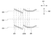
図3、図4および図5に示すように、フィン2の平面部21には、平面部21を切り起こすことにより鎧窓状のルーバ23が一体形成されている。ルーバ23は、チューブ1の積層方向(以下、チューブ積層方向X3という)から見たとき、平面部21に対して予め定めた角度で切り起こされており、空気流れ方向X1に沿って平面部21に複数設けられている。そして、隣り合うルーバ23間には、空気が流通可能なルーバ間通路230が形成されている。
As shown in FIGS. 3, 4 and 5, the
本実施形態では、図3に示すように、1つの平面部21に形成された複数のルーバ23は、空気流れ上流側に位置する複数のルーバ23を含む上流ルーバ群と、空気流れ下流側に位置する複数のルーバ23を含む下流ルーバ群に二分されている。そして、上流ルーバ群に属するルーバ23の切り起こし方向と、下流ルーバ群に属するルーバ23の切り起こし方向とが異なっている。つまり、上流ルーバ群と下流ルーバ群とは、それぞれに属するルーバ23の切り起こし方向が逆に形成されている。
In the present embodiment, as shown in FIG. 3, the plurality of
平面部21の空気流れ上流側の端部は、ルーバ23が形成されていない上流側平面部24となっている。同様に、平面部21の空気流れ下流側の端部は、ルーバ23が形成されていない下流側平面部25となっている。
An end portion of the
平面部21の空気流れ方向X1における略中央部、すなわち上流ルーバ群と下流ルーバ群との間は、ルーバ23が形成されておらず、空気流れ方向が反転する転向部26として構成されている。換言すると、上流ルーバ群と下流ルーバ群との間には、空気流れ方向X1と略平行に形成された転向部26が設けられている。この転向部26を介して、上流ルーバ群と下流ルーバ群とは、それぞれに属するルーバ23の切り起こし方向が反転している。
The
複数のルーバ23のうち空気流れ最上流側に配置される上流端ルーバ23aは、上流側平面部24に接続されている。また、複数のルーバ23のうち空気流れ最下流側に配置される下流端ルーバ23bは、下流側平面部25に接続されている。
The
ルーバ23は、転向部26の空気流れ上流側と下流側とに同枚数ずつ配設されている。本実施形態では、複数のルーバ23は、平面部21の空気流れ方向の中心線(仮想線)C1に対して対称に配置されている。
The same number of
図3、図4および図5において、二点鎖線は、フィン2におけるチューブ積層方向X3に垂直な断面において、隣り合う平面部21間の中心線(仮想線)C2を示している。また、図4および図5において、破線は、フィン2の板厚方向における中心線(仮想線)C3を示している。なお、図4および図5において、複数の一点鎖線は、チューブ長手方向X2に平行な仮想線である。
3, 4, and 5, the alternate long and two short dashes line indicates the center line (virtual line) C2 between the adjacent
ここで、フィン2におけるチューブ積層方向X3に垂直な断面において、隣り合う平面部21間の中心線C2からの最短距離をLとしたとき、フィン2の空気流れ上流側端部からの距離と最短距離Lとの関係を図6に示す。なお、図6の縦軸に示すL比とは、フィン2のうち最短距離Lが最大となる場合の最短距離Lを1として表した最短距離Lの値のことである。
Here, in a cross section of the
図6に示すように、フィン2の平面部21における空気流れ上流側端部、空気流れ下流側端部および空気流れ方向の中央部において、最短距離Lが最大になっている。換言すると、平面部21における上流側平面部24、下流側平面部25および転向部26において、最短距離Lが最大になっている。したがって、本実施形態の上流側平面部24、下流側平面部25および転向部26が、最遠部に相当している。
As shown in FIG. 6, the shortest distance L is maximum at the air flow upstream end, the air flow downstream end, and the center in the air flow direction of the
本実施形態では、平面部21における最短距離Lが最大となる部位(上流側平面部24、下流側平面部25および転向部26)のうち、転向部26にスリット27が形成されている。このとき、スリット27は、チューブ1の空気流れ方向X1の上流側端部および下流側端部のそれぞれから最も離れている部位に設けられている。
In the present embodiment, the
スリット27は、平面部21を、当該平面部21に隣接する一方の湾曲部22から他方の湾曲部22に向かって切り込むことにより形成されている。スリット27は、平面視(チューブ長手方向X2から見た状態)において略矩形状となるように形成されている。スリット27は、チューブ積層方向X3から見たときにチューブ1と重合している。本実施形態では、フィン2は、スリット27を中心として、空気流れ方向X1の上流側と下流側とが対称形状となるように形成されている。
The
このスリット27を設けることで、フィン2に空隙部が形成されている。したがって、本実施形態のスリット27が、本発明の空隙部に相当している。以下、スリット27の空気流れ方向X1の長さを、スリット巾(空隙部巾)Wという。本実施形態では、スリット巾Wは、チューブ1およびフィン2間の空間の内接円の直径よりも大きくなっている。
By providing this
ここで、本発明者は、フィン2のフィンピッチFp(図2参照)およびスリット巾Wをそれぞれ変化させた場合において、凍結状態の解析を行った。この解析結果を図8に示す。
Here, the present inventor analyzed the frozen state when the fin pitch Fp (see FIG. 2) and the slit width W of the
具体的な解析条件としては、空気(外気)側の壁面境界の温度を15℃、熱伝導率を5W/m2K(自然対流相当)とするとともに、冷媒側の壁面境界の温度を−8℃、熱伝導率を∞W/m2Kとした。そして、図9に示すように、フィンピッチFPを一定としてスリット巾Wを変化させて、凝縮水の凍結時におけるチューブ1の変形量を計測し、その結果を図8に示している。図8の太破線の左側の領域では、チューブ1に変形が生じたことを示しており、図8の太破線の右側の領域では、チューブ1に変形が生じていないことを示している。
As specific analysis conditions, the temperature of the wall boundary on the air (outside air) side is 15 ° C., the thermal conductivity is 5 W / m 2 K (equivalent to natural convection), and the temperature of the wall boundary on the refrigerant side is −8. ° C, the thermal conductivity was ∞ W / m 2 K. Then, as shown in FIG. 9, the slit width W is changed while keeping the fin pitch FP constant, and the deformation amount of the
また、図10に、凍結時に後述する閉塞が発生する場合の凍結順序の解析結果を示している。なお、図10および後述する図11において、凍結部を点ハッチングで示し、未凍結部(未凍結の凝縮水が存在する領域)を網掛けハッチングで示している。 Further, FIG. 10 shows the analysis result of the freezing order when the later-described blockage occurs during freezing. In FIG. 10 and FIG. 11 to be described later, the frozen portion is indicated by dot hatching, and the unfrozen portion (area in which unfrozen condensed water exists) is indicated by hatching.
図10に示すように、チューブ1に0℃以下(氷点以下)の低圧冷媒が流れると、大気中の水蒸気が凝縮し、フィン2の隣り合う平面部21間で凍結する。凍結は伝熱部品であるフィン2から、フィン2の表面に沿って地図でいう等高線の如く徐々に膨らむように進行していく。本実施形態では、最短距離Lが短いルーバ23のチューブ長手方向X2の端部(図6におけるL比が小さい部位)から凍結が進行していく。このように凍結が進行していくと、最短距離Lが最大となる部位である最遠部(本実施形態では転向部26)に未凍結の凝縮水が残存し、この未凍結の凝縮水が内部に存在したまま外側が凍結した状態となる。
As shown in FIG. 10, when a low-pressure refrigerant of 0 ° C. or lower (freezing point or lower) flows through the
以下、未凍結の凝縮水が内部に存在する状態でその周りが凍結することを閉塞という。凍結時に閉塞が発生すると、内部に残存している未凍結の凝縮水が凍結する際の体積膨張により、フィン2およびチューブ1に負荷がかかり、その結果、フィン2やチューブ1を変形させて亀裂を生じさせ、ひいては冷媒漏れを引き起す。
Hereinafter, when the unfrozen condensed water is present inside and frozen around it is called blockage. When blockage occurs during freezing, the
一方、図11に、凍結時に閉塞が発生しない場合の凍結順序の解析結果を示している。図11に示すように、スリット巾Wが大きいと、凍結時に閉塞が起こらなくなる。この状態で未凍結の凝縮水が凍結して体積膨張したとしても、その負荷を大気解放側(大気側の外部)に逃がすことができる。このため、チューブ1の変形を抑制することができる。
On the other hand, FIG. 11 shows the analysis result of the freezing order when the blockage does not occur during freezing. As shown in FIG. 11, when the slit width W is large, blockage does not occur during freezing. In this state, even if the unfrozen condensed water freezes and expands in volume, the load can be released to the atmosphere release side (outside the atmosphere side). Therefore, the deformation of the
図8において、太破線より左側の領域では、凍結時に閉塞が発生したが、太破線より右側の領域では、凍結時に閉塞が発生していない。したがって、フィンピッチFpおよびスリット巾Wを、図8における太破線の右側の領域内に位置する関係とすることで、凍結時の閉塞によるチューブ1の変形を抑制できる。
In FIG. 8, the area on the left side of the thick broken line is occluded during freezing, but the area on the right side of the thick broken line is not occluded during freezing. Therefore, by setting the fin pitch Fp and the slit width W to be located in the region on the right side of the thick broken line in FIG. 8, the deformation of the
ところで、そもそも、チューブ1またはフィン2の表面温度が0℃以下(氷点以下)になった際にフィン2の表面に凝縮水が付着していなければ、凝縮水の凍結によるチューブ1およびフィン2の変形を防止することができる。
By the way, in the first place, if condensed water does not adhere to the surface of the
図8における太実線より右側の領域では、フィン2に設けたスリット27のスリット巾Wが大きいので、凝縮水を鉛直方向下方側に排出することができる。一方、図8における太実線より左側の領域では、スリット27のスリット巾Wが小さいので、凝縮水を排出することができない。
In the region on the right side of the thick solid line in FIG. 8, the slit width W of the
このため、本実施形態では、スリット巾Wは、図8における太実線より右側の領域となるように設定されている。具体的には、スリット巾W(単位:mm)およびフィンピッチFp(単位:mm)は、W>0.414×Fp+0.0575の関係を満たすように設定されている。 Therefore, in this embodiment, the slit width W is set to be on the right side of the thick solid line in FIG. Specifically, the slit width W (unit: mm) and the fin pitch Fp (unit: mm) are set so as to satisfy the relationship of W> 0.414 × Fp + 0.0575.
より具体的には、スリット巾Wは、次の数式1を満たすように設定されている。
More specifically, the slit width W is set so as to satisfy the following

但し、α(単位:°)は、フィン2における1つの湾曲部22に接続される2つの平面部21同士がなす角度であるフィン角度を示しており、FH(単位:mm)は、フィン2のチューブ積層方向X3の長さであるフィン高さを示している。また、θ(単位:°)は、ルーバ23の切り起こし角度を示しており、Lp(単位:mm)は、ルーバ23の長さ、すなわちルーバ23における当該ルーバ23表面を流れる空気の流れ方向に沿った長さの平均値を示している。また、aは次の数式2を、bは次の数式3をそれぞれ示している。
However, α (unit: °) indicates a fin angle that is an angle formed by two
ここで、フィン2のうち、表面に凝縮水が溜まる可能性がある部位を保水部という。本実施形態の室外熱交換器はダウンフロー型の熱交換器であるため、凝縮水は重力によりフィン2のうち鉛直方向下方側に移動する。このため、保水部は、フィン2のうち鉛直方向下方側に位置している。そして、スリット27は、フィン2の複数の平面部21のうち、最下方側から保水部よりも上方側までのそれぞれの平面部21に設けられている。
Here, a portion of the
以上説明したように、フィン2の平面部21にスリット27を設けることで、当該スリット27において凍結負荷を逃がすことができる。さらに本実施形態では、スリット27を、フィン2におけるチューブ積層方向X3に垂直な断面において、隣り合う平面部21間の中心線C2からの最短距離Lが最大となる部位に設けている。これによれば、フィン2のうち凍結負荷が最大となる部位において、凍結負荷を逃がすことができるので、チューブ1やフィン2に凍結割れが発生することを抑制できる。
As described above, by providing the
ところで、凝縮水の凍結時、図10および図11に示すように、転向部26には、未凍結の凝縮水が存在し易くなっている。このため、転向部26は、平面部21のうち凍結負荷が最大となる部位である。また、転向部26は、コア部3における空気流れ方向X1の中央部に存在するが、コア部3の空気流れ方向X1の中央部は凍結負荷によるチューブ1の変形量が最大となる部位である。
By the way, when the condensed water is frozen, as shown in FIGS. 10 and 11, unturned condensed water is likely to exist in the turning
これに対し、本実施形態では、スリット27を、チューブ1の空気流れ方向X1の上流側端部および下流側端部のそれぞれから最も離れている部位、すなわち空気流れ方向X1の中央部である転向部26に設けている。このため、平面部21のうち凍結負荷がかかった際に最もチューブ1が破損し易い部位において、凍結負荷を逃がすことが可能となる。
On the other hand, in the present embodiment, the
また、本実施形態では、フィン2を、スリット27を中心として、空気流れ方向X1の上流側と下流側とが対称形状となるように形成している。これによれば、フィン2の成形性を向上させることができる。
In addition, in the present embodiment, the
また、本実施形態では、室外熱交換器をダウンフロー型の熱交換器とするとともに、スリット27を、フィン2の複数の平面部21のうち、最下方側から保水部よりも上方側までのそれぞれの平面部21に設けている。これによれば、フィン2のうち保水部、すなわち凝縮水が付着する可能性がある部位にスリット27が設けられているので、チューブ1やフィン2に凍結割れが発生することを確実に抑制できる。
In addition, in the present embodiment, the outdoor heat exchanger is a downflow type heat exchanger, and the
(第2実施形態)
次に、本発明の第2実施形態について図12に基づいて説明する。本第2実施形態は、上記第1実施形態と比較して、スリット27に代えて貫通孔28を設けた点が異なるものである。
(Second embodiment)
Next, a second embodiment of the present invention will be described based on FIG. The second embodiment is different from the first embodiment in that a through
図12に示すように、本実施形態では、平面部21における最短距離Lが最大となる部位(上流側平面部24、下流側平面部25および転向部26)のうち、転向部26に円形状の貫通孔28が形成されている。本実施形態の貫通孔28が、本発明の空隙部に相当している。また、貫通孔28の直径が、スリット巾Wに相当している。
As shown in FIG. 12, in the present embodiment, among the parts (the upstream
本実施形態によれば、フィン2の平面部21に貫通孔8を設けることで、当該貫通孔28において凍結負荷を逃がすことができるので、上記第1実施形態と同様の効果を得ることが可能となる。
According to the present embodiment, by providing the through hole 8 in the
(第3実施形態)
次に、本発明の第3実施形態について図13に基づいて説明する。本第3実施形態は、上記第2実施形態と比較して、貫通孔28を三角形状とした点が異なるものである。
(Third Embodiment)
Next, a third embodiment of the present invention will be described based on FIG. The third embodiment is different from the second embodiment in that the through
図13に示すように、本実施形態では、平面部21における最短距離Lが最大となる部位(上流側平面部24、下流側平面部25および転向部26)のうち、転向部26に三角形状の貫通孔28が形成されている。このとき、貫通孔28の内接円の直径が、スリット巾Wに相当している。本実施形態によれば、フィン2の平面部21に貫通孔8を設けることで、当該貫通孔28において凍結負荷を逃がすことができるので、上記第1実施形態と同様の効果を得ることが可能となる。
As shown in FIG. 13, in the present embodiment, among the parts (the upstream
(第4実施形態)
次に、本発明の第4実施形態について図14に基づいて説明する。本第4実施形態は、上記第1実施形態と比較して、本発明の空隙部を2つのフィン2の隙間29により構成した点が異なるものである。
(Fourth Embodiment)
Next, a fourth embodiment of the present invention will be described based on FIG. The fourth embodiment is different from the first embodiment in that the void portion of the present invention is formed by the
図14に示すように、本実施形態では、フィン2は、空気流れ方向X1に2つ並んで設けられている。2つのフィン2は、互いに隙間29を設けて配置されている。この2つのフィン2同士の隙間29により、本発明の空隙部が構成されている。このとき、2つのフィン2同士の隙間29における空気流れ方向X1の長さが、スリット巾Wに相当している。
As shown in FIG. 14, in the present embodiment, two
本実施形態によれば、2つのフィン2同士の間に隙間29を設けることで、当該隙間29において凍結負荷を逃がすことができるので、上記第1実施形態と同様の効果を得ることが可能となる。
According to the present embodiment, by providing the
(第5実施形態)
次に、本発明の第5実施形態について図15に基づいて説明する。本第5実施形態は、上記第1実施形態と比較して、フィン2の平面部21に複数の転向部26を設けた点が異なるものである。
(Fifth Embodiment)
Next, a fifth embodiment of the present invention will be described based on FIG. The fifth embodiment is different from the first embodiment in that a plurality of turning
図15に示すように、本実施形態では、フィン2の平面部21に複数(本例では3つ)の転向部26が設けられている。転向部26は、平面部21に等間隔に配置されている。3つの転向部26のうち、空気流れ最下流側の転向部26には、スリット27が形成されている。
As shown in FIG. 15, in the present embodiment, the
複数の転向部26のうち空気流れ最下流側の転向部26は、空気の熱が伝わり難いので、凍結時に未凍結の凝縮水が存在し易くなり、凍結負荷が大きくなり易い。これに対し、本実施形態のように、複数の転向部26のうち空気流れ最下流側の転向部26にスリット27を設けることで、当該スリット27において凍結負荷を逃がすことができる。したがって、平面部21のうち凍結負荷がかかった際にチューブ1が破損し易い部位において、凍結負荷を逃がすことが可能となる。
Since the heat of the air is difficult to be transmitted to the turning
(第6実施形態)
次に、本発明の第6実施形態について図16に基づいて説明する。本第6実施形態は、上記第4実施形態と比較して、室外熱交換器を、冷媒を蒸発させて吸熱作用を発揮させる際に、蓄冷材を凝固させて冷熱を蓄え、蓄冷材が融解する際に蓄えられた冷熱を放冷する蓄冷熱交換器とした点が異なるものである。
(Sixth Embodiment)
Next, a sixth embodiment of the present invention will be described based on FIG. The sixth embodiment is different from the fourth embodiment in that when the outdoor heat exchanger evaporates the refrigerant to exert an endothermic effect, the cold storage material is solidified to store cold heat and the cold storage material melts. The difference is that it is a cold storage heat exchanger that discharges the cold heat stored when the cold storage is performed.
図16に示すように、本実施形態の室外熱交換器は、蓄冷材を収容する部屋を区画する蓄冷材容器6を有している。蓄冷材容器6は、チューブ1に接合されている。
As shown in FIG. 16, the outdoor heat exchanger of this embodiment includes a cool
具体的には、蓄冷材容器6は、チューブ長手方向X2から見た断面が略正方形状の3つの部屋部61と、部屋部61同士を接続する2つの通路部62を備えている。部屋部61は、通路部62よりも体積が大きい。部屋部61は、空気流れ方向X1に3つ並んで設けられている。
Specifically, the
3つの部屋部61は、互いに間隔を設けて配置されている。隣り合う2つの部屋部61同士は、通路部62により接続されている。したがって、3つの部屋部61は、通路部62を介して連通している。通路部62はチューブ1に接合されているが、通路部62とチューブ1との間には隙間が形成されている。
The three
3つの部屋部61のうち、2つの部屋部61の間に配置された部屋部61(以下、中央部屋部610という)は、チューブ1における空気流れ方向の中央部に接合されている。より詳細には、中央部屋部610は、チューブ積層方向X3から見たときに、2つのフィン2同士の隙間29(空隙部)と重合している。
Of the three
以上説明したように、本実施形態では、蓄冷材容器6(中央部屋部610)を、チューブ積層方向X3から見たときに、2つのフィン2同士の隙間29と重合するように設けることで、2つのフィン2同士の隙間29に、凍結時に熱負荷を加えることができる。これにより、凍結時に、コア部3の内方側に未凍結の凝縮水が残存することを抑制できるので、チューブ1やフィン2に凍結割れが発生することをより抑制できる。
As described above, in the present embodiment, the cool storage material container 6 (the central chamber portion 610) is provided so as to overlap with the
(第7実施形態)
次に、本発明の第7実施形態について図17に基づいて説明する。本第7実施形態は、上記第4実施形態と比較して、チューブ1に凹部11を設けた点が異なるものである。
(Seventh embodiment)
Next, a seventh embodiment of the present invention will be described based on FIG. The seventh embodiment differs from the fourth embodiment in that the
図17に示すように、本実施形態では、チューブ1における空気流れ方向の中央部に、チューブ積層方向X3に凹んだ凹部11が設けられている。凹部11は、チューブ積層方向X3から見たときに、2つのフィン2同士の隙間29(空隙部)と重合している。すなわち、凹部11は、チューブ1における隙間29と対向する部位に設けられている。
As shown in FIG. 17, in the present embodiment, a
これによれば、2つのフィン2同士の間の隙間29から凹部11に向かって凍結負荷を逃がすことができるので、凍結負荷をより逃がし易くできる。このため、チューブ1やフィン2に凍結割れが発生することをより抑制できる。
According to this, since the freezing load can be released from the
(第8実施形態)
次に、本発明の第8実施形態について図18および図19に基づいて説明する。本第8実施形態は、上記第1実施形態と比較して、フィン2の平面部21に複数の転向部26を設けた点が異なるものである。
(Eighth Embodiment)
Next, an eighth embodiment of the invention will be described with reference to FIGS. 18 and 19. The eighth embodiment differs from the first embodiment in that a plurality of turning
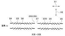
図18および図19に示すように、本実施形態では、フィン2の平面部21に複数(本例では3つ)の転向部26が設けられている。ルーバ23は、各転向部26において、切り起こし方向が反転するように構成されている。以下、複数の転向部26のうち、平面部21の空気流れ方向X1の端部からの距離が最大となる部位に配置された転向部26、すなわち、平面部21における空気流れ方向X1の中央部に配置された転向部26を、中央転向部260という。
As shown in FIGS. 18 and 19, in the present embodiment, a plurality of (three in this example) turning
中央転向部260は、他の転向部26よりも、空気流れ方向X1の長さが長く形成されている。複数の転向部26のうち、中央転向部26にはスリット27が設けられているが、その他の転向部26にはスリット27は設けられていない。
The
本実施形態によれば、フィン2の平面部21、具体的には中央転向部260にスリット27を設けることで、当該スリット27において凍結負荷を逃がすことができるので、上記第1実施形態と同様の効果を得ることが可能となる。
According to the present embodiment, the freezing load can be released in the
(他の実施形態)
本発明は上述の実施形態に限定されることなく、本発明の趣旨を逸脱しない範囲内で、以下のように種々変形可能である。また、上記各実施形態に開示された手段は、実施可能な範囲で適宜組み合わせてもよい。
(Other embodiments)
The present invention is not limited to the above-described embodiments, but can be variously modified as follows without departing from the spirit of the present invention. Further, the means disclosed in each of the above embodiments may be appropriately combined within a practicable range.
(1)上記実施形態では、平面部21における最短距離Lが最大となる部位である上流側平面部24、下流側平面部25および転向部26のうち、転向部26にスリット27または貫通孔28を形成した例について説明したが、スリット27または貫通孔28を設ける部位はこれに限定されない。
(1) In the above-described embodiment, among the upstream
例えば、スリット27または貫通孔28を、上流側平面部24および下流側平面部25のいずれかに形成してもよいし、上流側平面部24および下流側平面部25の双方に形成してもよい。また、スリット27または貫通孔28を、上流側平面部24、下流側平面部25および転向部26のうちの2箇所以上に形成してもよい。
For example, the
さらに、スリット27または貫通孔28を、平面部21における最短距離Lが最大となる部位である上流側平面部24、下流側平面部25および転向部26のうちの少なくとも1箇所に形成するのに加えて、平面部21における他の部位(平面部21における最短距離Lが最大とならない部位)にも形成してもよい。
Further, the
(2)上記第5実施形態では、スリット27を、複数の転向部26のうち、空気流れ最下流側の転向部26に設けた例について説明した。また、上記第8実施形態では、スリット27を、中央転向部260に設けた例について説明した。しかしながら、スリット27を設ける部位はこれらに限定されない。例えば、スリット27を、複数の転向部26の全てに設けてもよいし、複数の転向部26のうち任意の箇所に設けてもよい。
(2) In the fifth embodiment, the example in which the
(3)上記実施形態では、上流ルーバ群と下流ルーバ群とは、それぞれに属するルーバ23の切り起こし方向が反対(逆)になるように形成されているが、ルーバ23の切り起こし方向はこれに限定されない。例えば、複数のルーバ23を、平面部21における空気流れ方向X1の中心線C1に対して左右対称となるように形成してもよい。この場合、上流側ルーバ群に属するルーバ23と下流側ルーバ群に属するルーバ23とが同一形状であっても、成形性を向上させることができる。
(3) In the above-described embodiment, the upstream louver group and the downstream louver group are formed such that the
(4)上記実施形態では、本発明に係る熱交換器を、ヒートポンプサイクルにおける低圧冷媒を外気と熱交換させて蒸発させる蒸発器として機能する室外熱交換器に適用した例について説明したが、本発明に係る熱交換器の適用はこれに限定されない。例えば、不凍液(例えばLLC)の持つ熱を外気に放熱する放熱器に、本発明に係る熱交換器を適用してもよい。 (4) In the above embodiment, an example in which the heat exchanger according to the present invention is applied to an outdoor heat exchanger that functions as an evaporator that heat-exchanges a low-pressure refrigerant with outside air in a heat pump cycle to evaporate, is described. The application of the heat exchanger according to the invention is not limited to this. For example, the heat exchanger according to the present invention may be applied to a radiator that radiates the heat of the antifreeze liquid (for example, LLC) to the outside air.
1 チューブ
2 フィン
21 平面部
22 頂部
26 転向部(最遠部)
27 スリット(空隙部)
28 貫通孔(空隙部)
29 隙間(空隙部)
1
27 slits (voids)
28 Through hole (void)
29 Gap (void)
Claims (6)
前記チューブ(1)に接合されて前記チューブ(1)周りを流れる第2流体との熱交換面積を増大させるフィン(2)とを備え、
前記フィン(2)における前記第2流体の流れ方向に垂直な断面形状は、前記第2流体の流れ方向と略平行な複数の平面部(21)と、隣り合う平面部(21)間を繋ぐ頂部(22)とを有する波形状であり、
前記チューブ(1)および前記フィン(2)の少なくとも一方の表面温度が氷点以下になる可能性のある熱交換器であって、
前記フィン(2)の前記平面部(21)には、前記平面部(21)を切り起こすことによりルーバ(23)が一体形成されており、
前記フィン(2)の前記平面部(21)のうち前記第2流体の流れ方向の中央部における前記ルーバ(23)が形成されていない部位(26)には、前記チューブ(1)または前記フィン(2)に付着した水または水含有物が凍結する際に最終的に凍結する部位の凍結による体積膨張に伴う負荷を逃がすための空隙部(27、28)が設けられており、
前記チューブ(1)の内部には、前記第1流体が流れる第1流体通路が形成されており、
前記空隙部(27、28)の少なくとも一部は、前記チューブ(1)の積層方向から見たときに、前記第1流体通路と重なるように配置されており、
前記平面部(21)のうち前記空隙部(27、28)の外縁を構成する部位は、下方側に向けて突出する突出部が接続されていない平面状に形成されており、
前記空隙部(27、28)に対して前記第2流体の流れ方向上流側および下流側に位置する前記平面部(21)は、同一の前記フィン(2)により構成されており、
前記フィン(2)のフィンピッチをFp、前記空隙部(27、28)における前記第2流体の流れ方向の長さである空隙部巾をWとしたとき、前記フィンピッチおよび前記空隙部巾が、W>0.414×Fp+0.0575の関係を満たしていることを特徴とする熱交換器。 A plurality of laminated tubes (1) in which the first fluid flows,
A fin (2) joined to the tube (1) to increase a heat exchange area with a second fluid flowing around the tube (1),
A cross-sectional shape of the fin (2) perpendicular to the flow direction of the second fluid connects a plurality of flat surface portions (21) substantially parallel to the flow direction of the second fluid and adjacent flat surface portions (21). A corrugated shape having a top (22),
A heat exchanger in which the surface temperature of at least one of the tube (1) and the fin (2) may be below freezing,
A louver (23) is integrally formed on the plane portion (21) of the fin (2) by cutting and raising the plane portion (21),
The tube (1) or the fin (1) is provided in a portion ( 26) of the flat portion (21) of the fin (2) in the central portion in the flow direction of the second fluid where the louver (23) is not formed. When water or a water-containing substance attached to (2) freezes, voids (27, 28) are provided to release the load due to volume expansion due to freezing of the finally frozen portion,
A first fluid passage through which the first fluid flows is formed inside the tube (1),
At least a part of the void portion (27, 28) is arranged so as to overlap with the first fluid passage when viewed from the stacking direction of the tube (1) ,
A portion of the flat surface portion (21) forming an outer edge of the void portion (27, 28) is formed in a flat shape in which a protruding portion protruding downward is not connected,
The plane portions (21) located on the upstream side and the downstream side in the flow direction of the second fluid with respect to the void portions (27, 28) are configured by the same fin (2),
When the fin pitch of the fins (2) is Fp and the gap width which is the length of the gaps (27, 28) in the flow direction of the second fluid is W, the fin pitch and the gap width are , W> 0.414 × Fp + 0.0575.
前記チューブ(1)に接合されて前記チューブ(1)周りを流れる第2流体との熱交換面積を増大させるフィン(2)とを備え、
前記フィン(2)における前記第2流体の流れ方向に垂直な断面形状は、前記第2流体の流れ方向と略平行な複数の平面部(21)と、隣り合う平面部(21)間を繋ぐ頂部(22)とを有する波形状であり、
前記チューブ(1)および前記フィン(2)の少なくとも一方の表面温度が氷点以下になる可能性のある熱交換器であって、
前記フィン(2)の前記平面部(21)には、前記平面部(21)を切り起こすことによりルーバ(23)が一体形成されており、
前記フィン(2)の前記平面部(21)のうち前記第2流体の流れ方向の中央部における前記ルーバ(23)が形成されていない部位(26)には、前記チューブ(1)または前記フィン(2)に付着した水または水含有物が凍結する際に最終的に凍結する部位の凍結による体積膨張に伴う負荷を逃がすための空隙部(27、28)が設けられており、
前記チューブ(1)の内部には、前記第1流体が流れる第1流体通路が複数形成されており、
前記チューブ(1)は、複数の前記第1流体通路を挟んで対向する二つの扁平面(10a、10b)を有しており、
前記空隙部(27、28)の少なくとも一部は、前記チューブ(1)の積層方向から見たときに、前記チューブ(1)における複数の前記第1流体流路のうち少なくとも1つと重なるように配置されており、
前記フィン(2)における、前記第2流体の流れ方向に対する前記空隙部(27、28)の上流側および下流側は、前記チューブ(1)の前記扁平面(10a、10b)にそれぞれ接合されており、
前記平面部(21)のうち前記空隙部(27、28)の外縁を構成する部位は、下方側に向けて突出する突出部が接続されていない平面状に形成されており、
前記空隙部(27、28)に対して前記第2流体の流れ方向上流側および下流側に位置する前記平面部(21)は、同一の前記フィン(2)により構成されており、
前記フィン(2)のフィンピッチをFp、前記空隙部(27、28)における前記第2流体の流れ方向の長さである空隙部巾をWとしたとき、前記フィンピッチおよび前記空隙部巾が、W>0.414×Fp+0.0575の関係を満たしていることを特徴とする熱交換器。 A plurality of laminated tubes (1) in which the first fluid flows,
A fin (2) joined to the tube (1) to increase a heat exchange area with a second fluid flowing around the tube (1),
A cross-sectional shape of the fin (2) perpendicular to the flow direction of the second fluid connects a plurality of flat surface portions (21) substantially parallel to the flow direction of the second fluid and adjacent flat surface portions (21). A corrugated shape having a top (22),
A heat exchanger in which the surface temperature of at least one of the tube (1) and the fin (2) may be below freezing,
A louver (23) is integrally formed on the plane portion (21) of the fin (2) by cutting and raising the plane portion (21),
The tube (1) or the fin (1) is provided in a portion ( 26) of the flat portion (21) of the fin (2) in the central portion in the flow direction of the second fluid where the louver (23) is not formed. When water or a water-containing substance attached to (2) freezes, voids (27, 28) are provided to release the load due to volume expansion due to freezing of the finally frozen portion,
Inside the tube (1), a plurality of first fluid passages through which the first fluid flows are formed,
The tube (1) has two flat surfaces (10a, 10b) facing each other across the plurality of first fluid passages,
At least a part of the voids (27, 28) overlaps with at least one of the plurality of first fluid flow paths in the tube (1) when viewed in the stacking direction of the tube (1). Has been placed ,
The upstream side and the downstream side of the void (27, 28) in the fin (2) with respect to the flow direction of the second fluid are joined to the flat surfaces (10a, 10b) of the tube (1), respectively. Cage,
A portion of the flat surface portion (21) forming an outer edge of the void portion (27, 28) is formed in a flat shape in which a protruding portion protruding downward is not connected,
The plane portions (21) located on the upstream side and the downstream side in the flow direction of the second fluid with respect to the void portions (27, 28) are configured by the same fin (2),
When the fin pitch of the fins (2) is Fp and the gap width which is the length of the gaps (27, 28) in the flow direction of the second fluid is W, the fin pitch and the gap width are , W> 0.414 × Fp + 0.0575.
前記平面部(21)における複数の前記ルーバ(23)の間には、前記第2流体の流れ方向と略平行に形成された転向部(26)が設けられており、
前記空隙部(27、28)は、前記平面部(21)における前記第2流体の流れ方向の中央部に配置された前記転向部(26)に設けられていることを特徴とする請求項1または2に記載の熱交換器。 The flat portion (21) is provided with a plurality of the louvers (23) cut and raised at a predetermined cut and raised angle with respect to the flat portion (21) along the flow direction of the second fluid. Cage,
Between the plurality of louvers (23) in the flat portion (21), a turning portion (26) formed substantially parallel to the flow direction of the second fluid is provided.
The gap portion (27, 28) is according to claim 1, characterized in that provided the said turning portion arranged in the center portion of the second fluid flow direction (26) in said planar portion (21) Or the heat exchanger according to 2 .
特徴とする請求項1ないし5のいずれか1つに記載の熱交換器。 The heat exchanger according to any one of claims 1 to 5 , wherein the tube (1) is arranged so that the first fluid flows in a vertical direction.
Priority Applications (4)
| Application Number | Priority Date | Filing Date | Title |
|---|---|---|---|
| JP2014059756A JP6687967B2 (en) | 2014-03-24 | 2014-03-24 | Heat exchanger |
| PCT/JP2015/001614 WO2015146123A1 (en) | 2014-03-24 | 2015-03-23 | Heat exchanger |
| US15/126,442 US9939208B2 (en) | 2014-03-24 | 2015-03-23 | Heat exchanger |
| DE112015001451.9T DE112015001451T5 (en) | 2014-03-24 | 2015-03-23 | heat exchangers |
Applications Claiming Priority (1)
| Application Number | Priority Date | Filing Date | Title |
|---|---|---|---|
| JP2014059756A JP6687967B2 (en) | 2014-03-24 | 2014-03-24 | Heat exchanger |
Publications (3)
| Publication Number | Publication Date |
|---|---|
| JP2015183908A JP2015183908A (en) | 2015-10-22 |
| JP2015183908A5 JP2015183908A5 (en) | 2016-08-18 |
| JP6687967B2 true JP6687967B2 (en) | 2020-04-28 |
Family
ID=54194673
Family Applications (1)
| Application Number | Title | Priority Date | Filing Date |
|---|---|---|---|
| JP2014059756A Expired - Fee Related JP6687967B2 (en) | 2014-03-24 | 2014-03-24 | Heat exchanger |
Country Status (4)
| Country | Link |
|---|---|
| US (1) | US9939208B2 (en) |
| JP (1) | JP6687967B2 (en) |
| DE (1) | DE112015001451T5 (en) |
| WO (1) | WO2015146123A1 (en) |
Families Citing this family (11)
| Publication number | Priority date | Publication date | Assignee | Title |
|---|---|---|---|---|
| JP6409793B2 (en) | 2016-02-11 | 2018-10-24 | 株式会社デンソー | Intercooler |
| JP6432539B2 (en) * | 2016-02-12 | 2018-12-05 | 株式会社デンソー | Intercooler |
| DE102016213197A1 (en) * | 2016-07-19 | 2018-01-25 | Mahle International Gmbh | Corrugated rib of a heat exchanger and heat exchanger |
| JP2018132247A (en) * | 2017-02-15 | 2018-08-23 | 富士電機株式会社 | Automatic selling machine |
| WO2018154806A1 (en) * | 2017-02-21 | 2018-08-30 | 三菱電機株式会社 | Heat exchanger and air conditioner |
| CN114641663A (en) * | 2019-11-11 | 2022-06-17 | 三菱电机株式会社 | Heat exchanger and refrigeration cycle device |
| DE102020100105A1 (en) * | 2020-01-06 | 2021-07-08 | Volkswagen Aktiengesellschaft | Heat exchanger |
| WO2021224954A1 (en) | 2020-05-07 | 2021-11-11 | 三菱電機株式会社 | Humidity sensor and air conditioner |
| WO2022219719A1 (en) | 2021-04-13 | 2022-10-20 | 三菱電機株式会社 | Heat exchanger and refrigeration cycle device |
| CN117561416A (en) | 2021-06-29 | 2024-02-13 | 三菱电机株式会社 | Heat exchanger, refrigeration cycle device, and heat exchanger manufacturing method |
| JP7353518B1 (en) * | 2022-04-19 | 2023-09-29 | 三菱電機株式会社 | Heat exchangers and air conditioners |
Family Cites Families (28)
| Publication number | Priority date | Publication date | Assignee | Title |
|---|---|---|---|---|
| JPS5678966U (en) * | 1979-11-22 | 1981-06-26 | ||
| JPS58214793A (en) * | 1982-06-09 | 1983-12-14 | Mitsubishi Electric Corp | Heat exchanger |
| US5529116A (en) * | 1989-08-23 | 1996-06-25 | Showa Aluminum Corporation | Duplex heat exchanger |
| SE469552B (en) * | 1991-12-18 | 1993-07-26 | Volvo Ab | AIR BREATHING DEVICE ON A BRAIN PILLOW FILLER |
| JP2588114Y2 (en) | 1993-03-30 | 1999-01-06 | 株式会社日本クライメイトシステムズ | Automotive heat exchanger |
| JP3358380B2 (en) | 1995-04-21 | 2002-12-16 | 株式会社デンソー | Heat exchanger and its manufacturing method |
| US5992514A (en) | 1995-11-13 | 1999-11-30 | Denso Corporation | Heat exchanger having several exchanging portions |
| JPH10231724A (en) | 1997-02-19 | 1998-09-02 | Denso Corp | Heat-exchanger |
| JP3709611B2 (en) | 1995-12-15 | 2005-10-26 | 株式会社デンソー | Heat exchanger |
| JP3446427B2 (en) | 1995-11-13 | 2003-09-16 | 株式会社デンソー | Heat exchanger |
| JP3469412B2 (en) * | 1996-11-13 | 2003-11-25 | 株式会社豊田中央研究所 | Evaporator |
| US6209628B1 (en) | 1997-03-17 | 2001-04-03 | Denso Corporation | Heat exchanger having several heat exchanging portions |
| JP3855346B2 (en) | 1997-03-17 | 2006-12-06 | 株式会社デンソー | Heat exchanger |
| JPH11159987A (en) | 1997-11-29 | 1999-06-15 | Toyo Radiator Co Ltd | Corrugate fin for compound heat exchanger |
| KR100297189B1 (en) * | 1998-11-20 | 2001-11-26 | 황해웅 | High efficiency modular OEL heat exchanger with heat transfer promoting effect |
| JP4122608B2 (en) | 1998-12-10 | 2008-07-23 | 株式会社デンソー | Refrigerant evaporator |
| JP2001059690A (en) * | 1999-08-20 | 2001-03-06 | Zexel Valeo Climate Control Corp | Heat exchanger |
| KR100365022B1 (en) | 2000-05-04 | 2002-12-16 | 한국기계연구원 | Loop heat transfer device with high efficiency fin |
| JP4513207B2 (en) | 2000-12-21 | 2010-07-28 | ダイキン工業株式会社 | Air heat exchanger |
| JP4041654B2 (en) | 2001-01-31 | 2008-01-30 | カルソニックカンセイ株式会社 | Louver fin of heat exchanger, heat exchanger thereof, and method of assembling the louver fin |
| US20030102113A1 (en) | 2001-11-30 | 2003-06-05 | Stephen Memory | Heat exchanger for providing supercritical cooling of a working fluid in a transcritical cooling cycle |
| AU2003241693A1 (en) * | 2002-06-18 | 2003-12-31 | Showa Denko K.K. | Unit-type heat exchanger |
| FR2849174B1 (en) | 2002-12-23 | 2006-01-06 | Valeo Thermique Moteur Sa | HEAT EXCHANGE FINISH, ESPECIALLY COOLING, HEAT EXCHANGE MODULE COMPRISING SUCH FIN AND METHOD OF MANUFACTURING HEAT EXCHANGERS USING THE SAME |
| JP4683987B2 (en) | 2005-04-14 | 2011-05-18 | カルソニックカンセイ株式会社 | Fin structure of integrated heat exchanger |
| JP2007010176A (en) | 2005-06-28 | 2007-01-18 | Denso Corp | Heat exchanger |
| JP2007113802A (en) | 2005-10-18 | 2007-05-10 | Denso Corp | Evaporator |
| US7549465B2 (en) * | 2006-04-25 | 2009-06-23 | Lennox International Inc. | Heat exchangers based on non-circular tubes with tube-endplate interface for joining tubes of disparate cross-sections |
| JP2008309373A (en) | 2007-06-13 | 2008-12-25 | Denso Corp | Heat exchanger |
-
2014
- 2014-03-24 JP JP2014059756A patent/JP6687967B2/en not_active Expired - Fee Related
-
2015
- 2015-03-23 US US15/126,442 patent/US9939208B2/en not_active Expired - Fee Related
- 2015-03-23 DE DE112015001451.9T patent/DE112015001451T5/en not_active Ceased
- 2015-03-23 WO PCT/JP2015/001614 patent/WO2015146123A1/en active Application Filing
Also Published As
| Publication number | Publication date |
|---|---|
| JP2015183908A (en) | 2015-10-22 |
| US9939208B2 (en) | 2018-04-10 |
| DE112015001451T5 (en) | 2017-01-05 |
| WO2015146123A1 (en) | 2015-10-01 |
| US20170082381A1 (en) | 2017-03-23 |
Similar Documents
| Publication | Publication Date | Title |
|---|---|---|
| JP6687967B2 (en) | Heat exchanger | |
| US20120103583A1 (en) | Heat exchanger and fin for the same | |
| JP2006322698A (en) | Heat exchanger | |
| JP6011481B2 (en) | Heat exchanger fins | |
| WO2017073715A1 (en) | Aluminum extruded flat perforated tube and heat exchanger | |
| KR101977817B1 (en) | Heat exchanger | |
| US10352599B2 (en) | Evaporator | |
| JP2016534308A (en) | Heat exchanger and side plate | |
| JP2015017776A5 (en) | ||
| JP2018532093A (en) | Heat exchanger | |
| JP2014020580A (en) | Fin tube type heat exchanger | |
| CN103791750A (en) | Finned tube heat exchanger | |
| JP4122670B2 (en) | Heat exchanger | |
| JP6160385B2 (en) | Laminate heat exchanger | |
| JP2003185374A (en) | Tube for heat exchanger with optimized plate | |
| JP2010175167A (en) | Cold storage heat exchanger | |
| JP5958917B2 (en) | Finned tube heat exchanger | |
| JP6220692B2 (en) | Heat exchanger | |
| JP6717256B2 (en) | Refrigerant evaporator and manufacturing method thereof | |
| JP5063765B2 (en) | Heat exchanger, heat exchanger manufacturing method, refrigerator, and air conditioner | |
| JP5574737B2 (en) | Heat exchanger | |
| JP4617148B2 (en) | Heat exchanger | |
| JP6281422B2 (en) | Laminate heat exchanger | |
| JP2005083653A (en) | Refrigerant evaporator | |
| JP6659215B2 (en) | Heat exchanger |
Legal Events
| Date | Code | Title | Description |
|---|---|---|---|
| A521 | Request for written amendment filed |
Free format text: JAPANESE INTERMEDIATE CODE: A523 Effective date: 20160705 |
|
| A621 | Written request for application examination |
Free format text: JAPANESE INTERMEDIATE CODE: A621 Effective date: 20170215 |
|
| A131 | Notification of reasons for refusal |
Free format text: JAPANESE INTERMEDIATE CODE: A131 Effective date: 20180206 |
|
| A521 | Request for written amendment filed |
Free format text: JAPANESE INTERMEDIATE CODE: A523 Effective date: 20180223 |
|
| A131 | Notification of reasons for refusal |
Free format text: JAPANESE INTERMEDIATE CODE: A131 Effective date: 20180626 |
|
| A521 | Request for written amendment filed |
Free format text: JAPANESE INTERMEDIATE CODE: A523 Effective date: 20180809 |
|
| A02 | Decision of refusal |
Free format text: JAPANESE INTERMEDIATE CODE: A02 Effective date: 20181218 |
|
| A521 | Request for written amendment filed |
Free format text: JAPANESE INTERMEDIATE CODE: A523 Effective date: 20190314 |
|
| A911 | Transfer to examiner for re-examination before appeal (zenchi) |
Free format text: JAPANESE INTERMEDIATE CODE: A911 Effective date: 20190322 |
|
| A912 | Re-examination (zenchi) completed and case transferred to appeal board |
Free format text: JAPANESE INTERMEDIATE CODE: A912 Effective date: 20190517 |
|
| A521 | Request for written amendment filed |
Free format text: JAPANESE INTERMEDIATE CODE: A523 Effective date: 20200207 |
|
| A61 | First payment of annual fees (during grant procedure) |
Free format text: JAPANESE INTERMEDIATE CODE: A61 Effective date: 20200401 |
|
| R150 | Certificate of patent or registration of utility model |
Ref document number: 6687967 Country of ref document: JP Free format text: JAPANESE INTERMEDIATE CODE: R150 |
|
| LAPS | Cancellation because of no payment of annual fees |