JP4207331B2 - Double heat exchanger - Google Patents
Double heat exchanger Download PDFInfo
- Publication number
- JP4207331B2 JP4207331B2 JP27694199A JP27694199A JP4207331B2 JP 4207331 B2 JP4207331 B2 JP 4207331B2 JP 27694199 A JP27694199 A JP 27694199A JP 27694199 A JP27694199 A JP 27694199A JP 4207331 B2 JP4207331 B2 JP 4207331B2
- Authority
- JP
- Japan
- Prior art keywords
- fin
- heat exchanger
- fins
- tubes
- portions
- Prior art date
- Legal status (The legal status is an assumption and is not a legal conclusion. Google has not performed a legal analysis and makes no representation as to the accuracy of the status listed.)
- Expired - Fee Related
Links
Images


Classifications
-
- F—MECHANICAL ENGINEERING; LIGHTING; HEATING; WEAPONS; BLASTING
- F28—HEAT EXCHANGE IN GENERAL
- F28F—DETAILS OF HEAT-EXCHANGE AND HEAT-TRANSFER APPARATUS, OF GENERAL APPLICATION
- F28F1/00—Tubular elements; Assemblies of tubular elements
- F28F1/10—Tubular elements and assemblies thereof with means for increasing heat-transfer area, e.g. with fins, with projections, with recesses
- F28F1/12—Tubular elements and assemblies thereof with means for increasing heat-transfer area, e.g. with fins, with projections, with recesses the means being only outside the tubular element
- F28F1/126—Tubular elements and assemblies thereof with means for increasing heat-transfer area, e.g. with fins, with projections, with recesses the means being only outside the tubular element consisting of zig-zag shaped fins
- F28F1/128—Fins with openings, e.g. louvered fins
-
- F—MECHANICAL ENGINEERING; LIGHTING; HEATING; WEAPONS; BLASTING
- F28—HEAT EXCHANGE IN GENERAL
- F28D—HEAT-EXCHANGE APPARATUS, NOT PROVIDED FOR IN ANOTHER SUBCLASS, IN WHICH THE HEAT-EXCHANGE MEDIA DO NOT COME INTO DIRECT CONTACT
- F28D1/00—Heat-exchange apparatus having stationary conduit assemblies for one heat-exchange medium only, the media being in contact with different sides of the conduit wall, in which the other heat-exchange medium is a large body of fluid, e.g. domestic or motor car radiators
- F28D1/02—Heat-exchange apparatus having stationary conduit assemblies for one heat-exchange medium only, the media being in contact with different sides of the conduit wall, in which the other heat-exchange medium is a large body of fluid, e.g. domestic or motor car radiators with heat-exchange conduits immersed in the body of fluid
- F28D1/04—Heat-exchange apparatus having stationary conduit assemblies for one heat-exchange medium only, the media being in contact with different sides of the conduit wall, in which the other heat-exchange medium is a large body of fluid, e.g. domestic or motor car radiators with heat-exchange conduits immersed in the body of fluid with tubular conduits
- F28D1/0408—Multi-circuit heat exchangers, e.g. integrating different heat exchange sections in the same unit or heat exchangers for more than two fluids
- F28D1/0426—Multi-circuit heat exchangers, e.g. integrating different heat exchange sections in the same unit or heat exchangers for more than two fluids with units having particular arrangement relative to the large body of fluid, e.g. with interleaved units or with adjacent heat exchange units in common air flow or with units extending at an angle to each other or with units arranged around a central element
- F28D1/0435—Combination of units extending one behind the other
-
- F—MECHANICAL ENGINEERING; LIGHTING; HEATING; WEAPONS; BLASTING
- F28—HEAT EXCHANGE IN GENERAL
- F28D—HEAT-EXCHANGE APPARATUS, NOT PROVIDED FOR IN ANOTHER SUBCLASS, IN WHICH THE HEAT-EXCHANGE MEDIA DO NOT COME INTO DIRECT CONTACT
- F28D21/00—Heat-exchange apparatus not covered by any of the groups F28D1/00 - F28D20/00
- F28D2021/0019—Other heat exchangers for particular applications; Heat exchange systems not otherwise provided for
- F28D2021/008—Other heat exchangers for particular applications; Heat exchange systems not otherwise provided for for vehicles
- F28D2021/0084—Condensers
-
- F—MECHANICAL ENGINEERING; LIGHTING; HEATING; WEAPONS; BLASTING
- F28—HEAT EXCHANGE IN GENERAL
- F28D—HEAT-EXCHANGE APPARATUS, NOT PROVIDED FOR IN ANOTHER SUBCLASS, IN WHICH THE HEAT-EXCHANGE MEDIA DO NOT COME INTO DIRECT CONTACT
- F28D21/00—Heat-exchange apparatus not covered by any of the groups F28D1/00 - F28D20/00
- F28D2021/0019—Other heat exchangers for particular applications; Heat exchange systems not otherwise provided for
- F28D2021/008—Other heat exchangers for particular applications; Heat exchange systems not otherwise provided for for vehicles
- F28D2021/0091—Radiators
- F28D2021/0094—Radiators for recooling the engine coolant
-
- F—MECHANICAL ENGINEERING; LIGHTING; HEATING; WEAPONS; BLASTING
- F28—HEAT EXCHANGE IN GENERAL
- F28F—DETAILS OF HEAT-EXCHANGE AND HEAT-TRANSFER APPARATUS, OF GENERAL APPLICATION
- F28F9/00—Casings; Header boxes; Auxiliary supports for elements; Auxiliary members within casings
- F28F9/001—Casings in the form of plate-like arrangements; Frames enclosing a heat exchange core
- F28F2009/004—Common frame elements for multiple cores
-
- F—MECHANICAL ENGINEERING; LIGHTING; HEATING; WEAPONS; BLASTING
- F28—HEAT EXCHANGE IN GENERAL
- F28F—DETAILS OF HEAT-EXCHANGE AND HEAT-TRANSFER APPARATUS, OF GENERAL APPLICATION
- F28F2215/00—Fins
- F28F2215/02—Arrangements of fins common to different heat exchange sections, the fins being in contact with different heat exchange media
Landscapes
- Engineering & Computer Science (AREA)
- Physics & Mathematics (AREA)
- Thermal Sciences (AREA)
- Mechanical Engineering (AREA)
- General Engineering & Computer Science (AREA)
- Geometry (AREA)
- Heat-Exchange Devices With Radiators And Conduit Assemblies (AREA)
- Air-Conditioning For Vehicles (AREA)
- Details Of Heat-Exchange And Heat-Transfer (AREA)
Description
【0001】
【発明の属する技術分野】
本発明は、異種の熱交換部(コア部)を有する複式熱交換器に関するもので、車両用冷凍サイクル(空調装置)のコンデンサ(放熱器、凝縮器)とエンジン冷却水を冷却するラジエータとが一体となったものに適用して有効である。
【0002】
【従来の技術】
複式熱交換器は、前述のごとく、異種のコア部が一体化された熱交換器であるため、両コア部の要求仕様が必ずしも一致しない。このため、例えばコンデンサコア部及びラジエータコア部がフィンにて一体成形されている場合において、ラジエータチューブのピッチ寸法とコンデンサチューブのピッチ寸法とを同じ寸法とした状態で、ラジエータチューブの厚みをコンデンサチューブの厚みより大きくすると、コンデンサフィンの高さをラジエータフィンの高さより高くせざるを得ない。
【0003】
このとき、コンデンサフィンとラジエータフィンとが一体化されている場合には、両フィンの展開寸法(山部及び谷部を延ばしてフィンを平坦な平板状としたときの長手方向寸法)を等しくせざるを得ないので、単純に両フィンの高さを相違させることはできない。
【0004】
そこで、特開平11−148795号公報に記載の発明では、折り曲げ形成されたフィンの山部及び谷部の曲率半径を相違させることでフィン高さを相違させている。具体的には、ラジエータフィンの曲率半径をコンデンサフィンの曲率半径より小さくすることにより、ラジエータフィンの高さをコンデンサフィンの高さより高くている。
【0005】
【発明が解決しようとする課題】
ところで、複式熱交換器に限らず、複数本のチューブを有するいわゆるマルチフロー型の熱交換器では、一般的に、熱交換器(コア部)の製造時においては、チューブとフィンとを交互に積層して仮組み(仮固定)した後に、炉内で加熱してチューブやフィン等をろう付け接合する。
【0006】
このとき、コンデンサフィンの山部及び谷部の曲率半径とラジエータフィンの山部及び谷部の曲率半径が相違していると、例えコンデンサフィンの材質及び板厚とラジエータフィンの材質及び板厚とが同じであっても、チューブとフィンとを仮組み(仮固定)する際の拘束力に対するコンデンサフィンの変形量(変形特性)とラジエータフィンの変形量(変形特性)とが相違してしまうので、仮組み(仮固定)作業時にコンデンサフィンとコンデンサチューブとの接触面圧と、ラジエータフィンとラジエータチューブとの接触面圧との間に比較的大きな差が発生してしまい、ろう付け不良等の不具合が発生するおそれがある。
【0007】
また、フィンの山部及び谷部の曲率半径が小さくなると、ろう付け時にチューブとフィンとの接合箇所にフィレットが形成され難くなるため、チューブからフィンへ熱を伝導させる部位が小さくなり、熱交換能力の低下を招く。
【0008】
本発明は、上記点に鑑み、フィンの山部及び谷部の曲率半径を大きく相違させることなく、複式熱交換器のフィンを一体化することを目的とする。
【0009】
【課題を解決するための手段】
本発明は、上記目的を達成するために、請求項1に記載の発明では、複式熱交換器において、第1、2フィン(112、122)は、互いに一体に形成されているとともに、かつ、折り曲げ形成された複数箇所の山部(112b、122b)及び谷部(112c、122c)と、隣り合う山部(112b、122b)及び谷部(112c、122c)間を繋ぐ平面部(112d、122d)とからなる波状のコルゲートフィンであり、第1、2フィン(112、122)を部分的に結合する結合部(f)が、複数箇所の山部(112b、122b)おきに設けられており、さらに、第1フィン(112)の平面部(112d)の傾き角度(θ1)と、第2フィン(122)の平面部(122d)の傾き角度(θ2)とが相違していることを特徴とする。
【0010】
これにより、平面部(112d、122d)の傾き角度とともに、フィン高さが変化するので、第1、2フィン(112、122)の山部(112b、122b)及び谷部(112c、122c)の曲率半径を等しくした状態で、第1フィン(112)のフィン高さと第2フィン(122)のフィン高さを相違させることができる。
【0011】
したがって、複式熱交換器の仮組作業時に、両フィン(112、122)と両チューブ(111、121)と略等しい接触面圧にて接触させることができるので、両者(111、121、112、122)のろう付け不良を防止することが可能となる。
【0012】
また、両フィン(112、122)の山部(112b、122b)及び谷部(112c、122c)の曲率半径を適切な値とすることができるので、チューブ(111、121)とフィン(112、122)との接合箇所に適正なフィレットを形成することができ、複式熱交換器の熱交換能力の低下を防止することが可能となる。
【0013】
請求項2に記載の発明では、複式熱交換器において、第1、2フィン(112、122)は、互いに一体に形成されているとともに、かつ、頂部に両チューブ(111、121)の長手方向と略平行な平板部(112a、122a)を有するように矩形状に折り曲げられた複数箇所の山部(112b、122b)及び谷部(112c、122c)と、隣り合う山部(112b、122b)及び谷部(112c、122c)間を繋ぐ平面部(112d、122d)とからなるコルゲートフィンであり、第1、2フィン(112、122)を部分的に結合する結合部(f)が、複数箇所の山部(112b、122b)おきに設けられており、さらに、第1フィン(112)の平板部(112a)の長さ(L1)と、第2フィン(122)の平板部(122a)の長さ(L2)とが相違していることを特徴とする。
【0014】
これにより、展開寸法を等しくした状態では、請求項1に記載の発明と同様に、第1フィン(112)の平面部(112d)の傾き角度(θ1)と、第2フィン(122)の平面部(122d)の傾き角度(θ2)とが相違するので、第1、2フィン(112、122)の山部(112b、122b)及び谷部(112c、122c)の曲率半径を等しくした状態で、第1フィン(112)のフィン高さと第2フィン(122のフィン高さを相違させることができる。
【0015】
したがって、複式熱交換器の仮組作業時に、両フィン(112、122)と両チューブ(111、121)と略等しい接触面圧にて接触させることができるので、両者(111、121、112、122)のろう付け不良を防止ことが可能となる。
【0016】
また、両フィン(112、122)の山部(112b、122b)及び谷部(112c、122c)の曲率半径を適切な値とすることができるので、チューブ(111、121)とフィン(112、122)との接合箇所に適正なフィレットを形成することができ、複式熱交換器の熱交換能力の低下を防止することが可能となる。
【0017】
請求項3に記載の発明では、複式熱交換器において、第1、2フィン(112、122)は、互いに一体に形成されているとともに、かつ、折り曲げ形成された複数箇所の山部(112b、122b)及び谷部(112c、122c)と、隣り合う山部(112b、122b)及び谷部(112c、122c)間を繋ぐ平面部(112d、122d)とからなる波状のコルゲートフィンであり、第1フィン(112)と第2フィン(122)とを所定寸法以上離隔させた状態で両フィン(112、122)を部分的に結合する結合部(f)が設けられており、さらに、第1フィン(112)の平面部(112d)の傾き角度(θ1)と、第2フィン(122)の平面部(122d)の傾き角度(θ2)とが相違していることを特徴とする。
【0018】
これにより、請求項1に記載の発明と同様に、両フィン(112、122)と両チューブ(111、121)と略等しい接触面圧にて接触させることができ、両者(111、121、112、122)のろう付け不良を防止できるとともに、チューブ(111、121)とフィン(112、122)との接合箇所に適正なフィレットを形成することができ、複式熱交換器の熱交換能力の低下を防止するこするとが可能となる。
【0019】
請求項4に記載の発明では、複式熱交換器において、第1、2フィン(112、122)は、互いに一体に形成されているとともに、かつ、頂部に両チューブ(111、121)の長手方向と略平行な平板部(112a、122a)を有するように矩形状に折り曲げられた複数箇所の山部(112b、122b)及び谷部(112c、122c)と、隣り合う山部(112b、122b)及び谷部(112c、122c)間を繋ぐ平面部(112d、122d)とからなるコルゲートフィンであり、第1フィン(112)と第2フィン(122)とを所定寸法以上離隔させた状態で両フィン(112、122)を部分的に結合する結合部(f)が設けられており、さらに、第1フィン(112)の平板部(112a)の長さ(L1)と、第2フィン(122)の平板部(122a)の長さ(L2)とが相違していることを特徴とする。
【0020】
これにより、請求項2に記載の発明と同様に、両フィン(112、122)と両チューブ(111、121)と略等しい接触面圧にて接触させることができ、両者(111、121、112、122)のろう付け不良を防止できるとともに、チューブ(111、121)とフィン(112、122)との接合箇所に適正なフィレットを形成することができ、複式熱交換器の熱交換能力の低下を防止することが可能となる。
【0021】
請求項5に記載の発明では、平面部(112d、122d)には、その一部を切り起こした鎧窓状のルーバ(112e、122e)が形成されていることを特徴とする。
【0022】
これにより、両平面部(112d、122d)の傾き角度(θ1、θ2)が相違しているので、空気流れ上流側から見ると、両平面部(112d、122d)がずれた状態となる。したがって、空気流れ上流側に位置する平面部(112d)の端部で発生した温度境界層が空気流れ下流側に存在する平面部(122d)により乱されるので、より確実に温度境界層が成長することを防止でき、ルーバ(112e、122e)の存在と相まって確実に熱伝達率の向上を図ることができる。
【0023】
請求項6に記載の発明では、第1流体は、車両用冷凍サイクル内を循環する冷媒であり、一方、第2流体は、液冷式内燃機関の冷却液であり、さらに、第1フィン(112)のフィン高さ(H1)は、第2フィン(122)のフィン高さ(H2)より高いことを特徴とする。
【0024】
これにより、液冷式内燃機関の冷却液が流通する第2チューブ(121)の通路断面積を大きくすることができるので、第2熱交換器(120)の通水抵抗を小さくすることができる。
【0025】
因みに、上記各手段の括弧内の符号は、後述する実施形態に記載の具体的手段との対応関係を示す一例である。
【0026】
【発明の実施の形態】
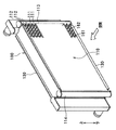
本実施形態は、本発明に係る複式熱交換器を車両用冷凍サイクル(空調装置)のコンデンサ(放熱器、凝縮器)と水冷エンジン(液冷式内燃機関)の冷却水(冷却液)を冷却するラジエータとが一体となったものに適用したものである。そして、図1は本実施形態に係る複式熱交換器100を空気流れ上流側から見た斜視図であり、図3は、水冷エンジン側(空気流れ下流側)から見た斜視図である。
【0027】
図1中、110は冷凍サイクル内を循環する冷媒と空気とを熱交換させて冷媒を冷却するコンデンサ(第1熱交換器)であり、このコンデンサ110は、冷媒(第1流体)が流通する複数本のコンデンサチューブ111、各コンデンサチューブ111間に配設されて冷媒と空気との熱交換を促進するコンデンサフィン(第1フィン)112、及びコンデンサチューブ111の長手方向両端側に配設されて各コンデンサチューブ111と連通するヘッダタンク113、114等から構成されている。
【0028】
因みに、紙面右側のヘッダタンク113は、各コンデンサチューブ111に冷媒を分配供給するものであり、紙面左側のヘッダタンク114は、各コンデンサチューブ111にて熱交換を終えた冷媒を集合回収するものである。
【0029】
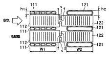
なお、コンデンサチューブ111は、図3に示すように、内部に多数本の冷媒通路111aが形成された多穴構造であり、押し出し加工又は引き抜き加工にて扁平状に形成されている。また、コンデンサフィン112は、後述するラジエータフィン122と一体化されており、その詳細は後述する。
【0030】
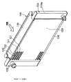
一方、図2中、120は水冷エンジンから流出する冷却水と空気とを熱交換して冷却水を冷却するラジエータであり、このラジエータ120は、冷却水(第2流体)が流通する複数本のラジエータチューブ121、各ラジエータチューブ121間に配設されて冷媒と空気との熱交換を促進するラジエータフィン(第2フィン)122、及びラジエータチューブ121の長手方向両端側に配設されて各ラジエータチューブ121と連通するヘッダタンク123、124等から構成されている。
【0031】
なお、紙面左側のヘッダタンク123は、各ラジエータチューブ121に冷却水を分配供給するものであり、紙面右側のヘッダタンク124は、各ラジエータチューブ121にて熱交換を終えた冷却水を集合回収するものである。
【0032】
また、ラジエータチューブ121は、図3に示すように、単純な扁平形状であり、その短径寸法(厚み寸法)h2は、コンデンサチューブ111の短径寸法(厚み寸法)h1より大きくなっている。そして、本実施形態では、両チューブ111、121の長径寸法(幅寸法)W1、W2は略等しく、かつ、その長径方向は、空気流れに沿った方向である。
【0033】
因みに、コンデンサチューブ111では冷媒が気相冷媒から液相冷媒に相変化しながら流通するのに対して、ラジエータチューブ121では冷却水が相変化せずに流通するので、一般的にラジエータチューブ121の通路断面積をコンデンサチューブ111の通路断面積より大きくすることが望ましい。
【0034】
また、130はコンデンサ110及びラジエータ120の端部に配設されて両者110、120の補強部材をなすサイドプレートであり、両チューブ111、121、両フィン112、122、両ヘッダタンク113、114、123、124及びサイドプレート130は、ろう付けにて一体接合されている。
【0035】
次に、両フィン112、122について述べる。
【0036】
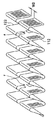
両フィン112、122は、図3、4に示すように、ローラ成型法にて互いに一体に形成されているとともに、かつ、頂部に両チューブ111、121の長手方向と略平行な平板部112a、122aを有するように矩形状に折り曲げられた複数箇所の山部112b、122b及び谷部112c、122cと、隣り合う山部112b、122b及び谷部112c、122c間を繋ぐ平面部112d、122dとからなる略矩形波状のコルゲートフィンである。
【0037】
そして、平面部112d、122dには、両フィン112、122を通過する空気の流れを乱して温度境界層が成長することを防止すべく、その一部を切り起こして鎧窓状としたルーバ112e、122eが形成されいるとともに、図5に示すように、コンデンサフィン112とラジエータフィン122とを所定寸法W3以上離隔させた状態で両フィン112、122を部分的に結合する結合部fが、複数箇所の山部112b、122bおきに設けられている。
【0038】
ここで、所定寸法W3は、少なくとも両フィン112、122の板厚より大きい寸法であって、図6に示すように、コンデンサフィン112の平面部112dの傾き角度θ1と、ラジエータフィン122の平面部122dの傾き角度θ2とを相違させたときに、両平面部112d、122dの傾き角度θ1、θ2を吸収することができる程度にねじれ変形し得る程度の寸法である。
【0039】
なお、図4、5に示すように、コンデンサフィン112とラジエータフィン122とを所定寸法W3以上離隔させることにより形成されたスリット(空間)Sは、ラジエータ120側からコンデンサ110側に熱が移動することを抑制する熱移動抑止手段として機能する。
【0040】
次に、本実施形態の特徴を述べる。
【0041】
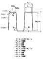
コンデンサフィン112とラジエータフィン122との展開寸法及びピッチ寸法(山部と山部との距離)を等しくした状態で、本実施形態のごとく、コンデンサフィン112の平面部112dの傾き角度θ1と、ラジエータフィン122の平面部122dの傾き角度θ2とを相違させると、図6に示すように、傾き角度が小さい方のフィン(本実施形態では、コンデンサフィン112)の平板部112aの長さL1が、傾き角度が大きい方のフィン(本実施形態では、ラジエータフィン122)の平板部122aの長さL2より小さくなるとともに、傾き角度が小さい方のフィンフィン高さ(山部と谷部との高低差)H1が傾き角度が大きいフィンのフィン高さH2より高くなる。
【0042】
したがって、コンデンサフィン112の山部112b及び谷部112cと平面部112dとの連結部112fの曲率半径r1と、ラジエータフィン112の山部122b及び谷部122cと平面部122dとの連結部122fの曲率半径r2とを等しくした状態で、コンデンサフィン112のフィン高さH1とラジエータフィン122のフィン高さH1とを相違させることができる。
【0043】
延いては、複式熱交換器100の仮組作業時に、両フィン112、122と両チューブ111、121とを略等しい接触面圧にて接触させることができるので、両者111、121、112、122のろう付け不良を防止できる。
【0044】
なお、平板部112a、122aの長さL1、L2とは、山部112b、122b(谷部112c、122c)のうち両チューブ111、121の長手方向と平行な部位の寸法を言うものである。また、平板部112a、122aは、図4、6に示すように、両チューブ111、121の長手方向に対して完全に平行となるもののみを言うものではなく、例えば図7に示すように、連結部112f、122fの曲率半径r1、r2より大きい曲率半径にて湾曲している場合も含むものである。
【0045】
また、両フィン112、122の山部112b、122b及び谷部112c、122cの曲率半径を適切な値とすることができるので、チューブ111、121とフィン112、122との接合箇所に適正なフィレットを形成することができ、複式熱交換器100の熱交換能力の低下を防止できる。
【0046】
また、両平面部112d、122dの傾き角度θ1、θ2が相違しているので、空気流れ上流側から見ると、両平面部112d、122dがずれた状態となる(図6参照)。したがって、空気流れ上流側に位置する平面部112dの端部で発生した温度境界層が空気流れ下流側に存在する平面部122dにより乱されるので、より確実に温度境界層が成長することを防止でき、ルーバ112e、122eの存在と相まって確実に熱伝達率の向上を図ることができる。
【0047】
ところで、上述の実施形態では、両フィン112、122は矩形波状のコルゲートフィンであったが、正弦波状のコルゲートフィンであってもよい。なお、この場合においては、平板部112a、122aが形成されず、一定の曲率半径にて湾曲した形状となる。
【0048】
また、上述の実施形態では、スリットSは、所定の幅寸法(W3)を有するものであったが、幅寸法(W3)が極めて小さくなるように線状に切断したスリットSとしてもよい。なお、この場合、コンデンサフィン112の平面部112dの傾き角度θ1と、ラジエータフィン122の平面部122dの傾き角度θ2とを相違させるべく、結合部fを複数箇所の山部112b、122bおき設定する必要がある。
【0049】
一方、上述の実施形態のごとく、スリットSに所定の幅寸法(W3)を持たせた場合には、結合部fを全ての平面部112d、122dに設けてもよい。
【0050】
また、上述の実施形態では、両フィン112、122のピッチ寸法を一致させたが、結合部fを複数箇所の山部112b、122bおき設定した場合には、図8に示すように、一の結合部fと他の結合部fとの間で、両フィン112、122のピッチ寸法(山部112b、122b間の距離)Pを相違させてもよい。これにより、一の結合部fと他の結合部fとの間に存在する平面部112d、122dの傾きが相違するので、これに伴ってフィン高さも相違する。なお、この場合、両フィン112、122の形状は、正弦波状又は矩形波状のいずれの形状であってもよい。
【図面の簡単な説明】
【図1】本発明の実施形態に係る複式熱交換器を空気流れ上流側から見た斜視図である。
【図2】本発明の実施形態に係る複式熱交換器を空気流れ下流側から見た斜視図である。
【図3】本発明の実施形態に係る複式熱交換器の断面図である。
【図4】本発明の実施形態に係る複式熱交換器におけるフィンの斜視図である。
【図5】本発明の実施形態に係る複式熱交換器におけるフィンの斜視図である。
【図6】本発明の実施形態に係る複式熱交換器におけるフィンの正面図である。
【図7】本発明の実施形態に係る複式熱交換器におけるフィンの変形例を示す正面図である。
【図8】本発明の実施形態に係る複式熱交換器におけるフィンの変形例を示す正面図である。
【符号の説明】
112…コンデンサフィン、112a…平板部、112b…山部、
112c…谷部、112d…平面部、122…ラジエータフィン、
122a…平板部、122b…山部、112c…谷部、112d…平面部。[0001]
BACKGROUND OF THE INVENTION
The present invention relates to a dual heat exchanger having different types of heat exchanging parts (core parts), and includes a condenser (radiator, condenser) of a vehicle refrigeration cycle (air conditioner) and a radiator for cooling engine cooling water. It is effective when applied to a single unit.
[0002]
[Prior art]
As described above, the duplex heat exchanger is a heat exchanger in which different types of core parts are integrated, so that the required specifications of both core parts do not necessarily match. For this reason, for example, when the condenser core part and the radiator core part are integrally formed with fins, the thickness of the radiator tube is set so that the pitch dimension of the radiator tube is equal to the pitch dimension of the condenser tube. If it is larger than the thickness of the capacitor fin, the height of the capacitor fin must be made higher than the height of the radiator fin.
[0003]
At this time, if the capacitor fin and the radiator fin are integrated, the development dimensions of the fins (longitudinal dimensions when the fins are flattened by extending the peaks and valleys) are equalized. Since it is unavoidable, the height of both fins cannot be simply made different.
[0004]
Therefore, in the invention described in Japanese Patent Application Laid-Open No. 11-148895, the fin heights are made different by making the radii of curvature of the ridges and valleys of the fins formed bent. Specifically, by setting the radius of curvature of the radiator fin to be smaller than the radius of curvature of the capacitor fin, the height of the radiator fin is made higher than the height of the capacitor fin.
[0005]
[Problems to be solved by the invention]
By the way, not only a double heat exchanger but a so-called multiflow type heat exchanger having a plurality of tubes, in general, the tubes and the fins are alternately arranged during the manufacture of the heat exchanger (core part). After stacking and temporary assembly (temporary fixing), heating in a furnace and brazing and joining tubes and fins.
[0006]
At this time, if the curvature radius of the peak and valley of the capacitor fin and the curvature radius of the peak and valley of the radiator fin are different, for example, the material and plate thickness of the capacitor fin and the material and plate thickness of the radiator fin Since the deformation amount (deformation characteristic) of the capacitor fin and the deformation amount (deformation characteristic) of the radiator fin with respect to the restraining force when temporarily assembling (temporarily fixing) the tube and the fin are different. During temporary assembly (temporary fixing), a relatively large difference occurs between the contact surface pressure between the capacitor fin and the capacitor tube and the contact surface pressure between the radiator fin and the radiator tube. There is a risk of malfunction.
[0007]
In addition, if the radius of curvature of the ridges and valleys of the fin is reduced, fillets are less likely to be formed at the joint between the tube and the fin during brazing, so the portion that conducts heat from the tube to the fin is reduced and heat exchange is performed. It causes a decline in ability.
[0008]
An object of this invention is to integrate the fin of a duplex heat exchanger, without making the curvature radius of the peak part and trough part of a fin differ greatly in view of the said point.
[0009]
[Means for Solving the Problems]
In order to achieve the above object, according to the present invention, in the dual heat exchanger, the first and second fins (112, 122) are integrally formed with each other, and Plural ridges (112b, 122b) and valleys (112c, 122c) formed by bending, and planar portions (112d, 122d) connecting the adjacent ridges (112b, 122b) and valleys (112c, 122c). ) And wavy corrugated fins, and a coupling portion (f) for partially coupling the first and second fins (112, 122) is provided every plurality of peak portions (112b, 122b). Furthermore, the inclination angle (θ1) of the flat surface portion (112d) of the first fin (112) is different from the inclination angle (θ2) of the flat surface portion (122d) of the second fin (122). And
[0010]
As a result, the fin height changes with the inclination angle of the plane portions (112d, 122d), so that the peak portions (112b, 122b) and the valley portions (112c, 122c) of the first and second fins (112, 122). The fin height of the first fin (112) and the fin height of the second fin (122) can be made different with the curvature radius being equal.
[0011]
Accordingly, during temporary assembly work of the dual heat exchanger, both fins (112, 122) and both tubes (111, 121) can be brought into contact with each other at substantially the same contact surface pressure, so both (111, 121, 112, 122), it is possible to prevent the brazing failure.
[0012]
Moreover, since the curvature radius of the peak part (112b, 122b) and trough part (112c, 122c) of both fins (112, 122) can be made into an appropriate value, a tube (111, 121) and a fin (112, 122), an appropriate fillet can be formed at the joint location, and it is possible to prevent a decrease in the heat exchange capability of the dual heat exchanger.
[0013]
In the invention according to claim 2, in the dual heat exchanger, the first and second fins (112, 122) are integrally formed with each other, and the longitudinal direction of both tubes (111, 121) is formed at the top. And a plurality of crests (112b, 122b) and troughs (112c, 122c) bent in a rectangular shape so as to have flat plate parts (112a, 122a) substantially parallel to the crest, and adjacent crests (112b, 122b) And corrugated fins composed of flat portions (112d, 122d) connecting the valley portions (112c, 122c), and a plurality of coupling portions (f) partially coupling the first and second fins (112, 122). It is provided every other peak portion (112b, 122b), and further, the length (L1) of the flat plate portion (112a) of the first fin (112) and the flat plate portion of the second fin (122). Wherein the length of 122a) (L2) and is different.
[0014]
Thereby, in the state where the development dimensions are equal, the inclination angle (θ1) of the flat portion (112d) of the first fin (112) and the plane of the second fin (122) are the same as in the invention of claim 1. Since the inclination angle (θ2) of the portion (122d) is different, the radii of curvature of the peaks (112b, 122b) and the valleys (112c, 122c) of the first and second fins (112, 122) are made equal. The fin height of the first fin (112) can be different from the fin height of the second fin (122).
[0015]
Accordingly, during temporary assembly work of the dual heat exchanger, both fins (112, 122) and both tubes (111, 121) can be brought into contact with each other at substantially the same contact surface pressure, so both (111, 121, 112, 122), it is possible to prevent the brazing failure.
[0016]
Moreover, since the curvature radius of the peak part (112b, 122b) and trough part (112c, 122c) of both fins (112, 122) can be made into an appropriate value, a tube (111, 121) and a fin (112, 122), an appropriate fillet can be formed at the joint location, and it is possible to prevent a decrease in the heat exchange capability of the dual heat exchanger.
[0017]
In the invention according to claim 3, in the dual heat exchanger, the first and second fins (112, 122) are integrally formed with each other and are bent at a plurality of ridges (112b, 122b) and a trough (112c, 122c), and a corrugated fin having a corrugated shape composed of a planar portion (112d, 122d) connecting between the adjacent crest (112b, 122b) and trough (112c, 122c), A coupling portion (f) for partially coupling the fins (112, 122) with the first fin (112) and the second fin (122) spaced apart by a predetermined dimension or more is provided. The inclination angle (θ1) of the flat surface portion (112d) of the fin (112) is different from the inclination angle (θ2) of the flat surface portion (122d) of the second fin (122).
[0018]
Thereby, like the invention of Claim 1, both fins (112, 122) and both tubes (111, 121) can be made to contact with substantially equal contact surface pressure, both (111, 121, 112). , 122) can be prevented, and an appropriate fillet can be formed at the joint between the tube (111, 121) and the fin (112, 122), and the heat exchange capacity of the dual heat exchanger is reduced. Can be prevented.
[0019]
In the invention according to claim 4, in the dual heat exchanger, the first and second fins (112, 122) are formed integrally with each other, and the longitudinal direction of both tubes (111, 121) is formed at the top. And a plurality of crests (112b, 122b) and troughs (112c, 122c) bent in a rectangular shape so as to have flat plate parts (112a, 122a) substantially parallel to the crest, and adjacent crests (112b, 122b) And corrugated fins composed of flat portions (112d, 122d) connecting the valley portions (112c, 122c), and the first fin (112) and the second fin (122) are spaced apart by a predetermined dimension or more. A coupling portion (f) for partially coupling the fins (112, 122) is provided, and further, the length (L1) of the flat plate portion (112a) of the first fin (112), and the second Wherein the flat portion of the fin (122) the length of (122a) (L2) and is different.
[0020]
Thereby, like the invention of Claim 2, both fins (112, 122) and both tubes (111, 121) can be made to contact with substantially equal contact surface pressure, both (111, 121, 112). , 122) can be prevented, and an appropriate fillet can be formed at the joint between the tube (111, 121) and the fin (112, 122), and the heat exchange capacity of the dual heat exchanger is reduced. Can be prevented.
[0021]
The invention according to claim 5 is characterized in that an armor window-like louver (112e, 122e) is formed on the flat portion (112d, 122d) by cutting and raising a part thereof.
[0022]
Thereby, since the inclination angles (θ1, θ2) of the two flat portions (112d, 122d) are different, the two flat portions (112d, 122d) are shifted from the upstream side of the air flow. Therefore, the temperature boundary layer generated at the end of the plane portion (112d) located on the upstream side of the air flow is disturbed by the plane portion (122d) existing on the downstream side of the air flow, so that the temperature boundary layer grows more reliably. In combination with the presence of the louvers (112e, 122e), the heat transfer coefficient can be reliably improved.
[0023]
In the invention according to claim 6, the first fluid is a refrigerant that circulates in the refrigeration cycle for the vehicle, while the second fluid is a coolant for a liquid-cooled internal combustion engine. 112), the fin height ( H1 ) of the second fin (122) is higher than the fin height ( H2 ).
[0024]
Thereby, since the passage cross-sectional area of the 2nd tube (121) through which the cooling fluid of a liquid cooling internal combustion engine distribute | circulates can be enlarged, the water flow resistance of a 2nd heat exchanger (120) can be made small. .
[0025]
Incidentally, the reference numerals in parentheses of each means described above are an example showing the correspondence with the specific means described in the embodiments described later.
[0026]
DETAILED DESCRIPTION OF THE INVENTION
In this embodiment, the dual heat exchanger according to the present invention cools the condenser (radiator, condenser) of the refrigeration cycle (air conditioner) for the vehicle and the cooling water (coolant) of the water-cooled engine (liquid-cooled internal combustion engine). It is applied to the one that is integrated with the radiator. FIG. 1 is a perspective view of the
[0027]
In FIG. 1,
[0028]
Incidentally, the
[0029]
As shown in FIG. 3, the
[0030]
On the other hand, in FIG. 2,
[0031]
The
[0032]
As shown in FIG. 3, the
[0033]
Incidentally, in the
[0034]
[0035]
Next, both
[0036]
As shown in FIGS. 3 and 4, the
[0037]
Further, in order to prevent the temperature boundary layer from growing by disturbing the flow of air passing through the
[0038]
Here, the predetermined dimension W3 is at least larger than the thickness of the
[0039]
As shown in FIGS. 4 and 5, the slit (space) S formed by separating the
[0040]
Next, features of the present embodiment will be described.
[0041]
With the unfolded dimensions and pitch dimensions (distance between peaks and peaks) of the
[0042]
Accordingly, the radius of curvature r1 of the connecting
[0043]
As a result, both the
[0044]
The lengths L1 and L2 of the
[0045]
Moreover, since the curvature radius of the
[0046]
In addition, since the inclination angles θ1 and θ2 of the
[0047]
By the way, in the above-mentioned embodiment, although both the
[0048]
In the above-described embodiment, the slit S has a predetermined width dimension (W3). However, the slit S may be a linearly cut slit S so that the width dimension (W3) is extremely small. In this case, in order to make the inclination angle θ1 of the
[0049]
On the other hand, as in the above-described embodiment, when the slit S has a predetermined width dimension (W3), the coupling portion f may be provided on all the
[0050]
Moreover, in the above-mentioned embodiment, although the pitch dimension of both the
[Brief description of the drawings]
FIG. 1 is a perspective view of a dual heat exchanger according to an embodiment of the present invention as viewed from the upstream side of an air flow.
FIG. 2 is a perspective view of the dual heat exchanger according to the embodiment of the present invention as viewed from the downstream side of the air flow.
FIG. 3 is a cross-sectional view of a dual heat exchanger according to an embodiment of the present invention.
FIG. 4 is a perspective view of fins in the dual heat exchanger according to the embodiment of the present invention.
FIG. 5 is a perspective view of fins in the dual heat exchanger according to the embodiment of the present invention.
FIG. 6 is a front view of fins in the dual heat exchanger according to the embodiment of the present invention.
FIG. 7 is a front view showing a modified example of fins in the dual heat exchanger according to the embodiment of the present invention.
FIG. 8 is a front view showing a modified example of fins in the dual heat exchanger according to the embodiment of the present invention.
[Explanation of symbols]
112: Capacitor fins, 112a: Flat plate portion, 112b: Mountain portion,
112c ... Valley part, 112d ... Plane part, 122 ... Radiator fin,
122a ... Flat plate portion, 122b ... Mountain portion, 112c ... Valley portion, 112d ... Plane portion.
Claims (6)
第2流体が流通するとともに、前記第1チューブ(111)と平行な方向に延びる複数本の第2チューブ(121)、及び前記第2チューブ(121)間に配設された熱交換を促進する第2フィン(122)を有して構成され、前記第1熱交換器(110)より空気流れ下流側に配設された第2熱交換器(120)とを備え、
前記第1、2フィン(112、122)は、互いに一体に形成されているとともに、かつ、折り曲げ形成された複数箇所の山部(112b、122b)及び谷部(112c、122c)と、隣り合う前記山部(112b、122b)及び前記谷部(112c、122c)間を繋ぐ平面部(112d、122d)とからなる波状のコルゲートフィンであり、
前記第1、2フィン(112、122)を部分的に結合する結合部(f)が、複数箇所の前記山部(112b、122b)おきに設けられており、
さらに、前記第1フィン(112)の前記平面部(112d)の傾き角度(θ1)と、前記第2フィン(122)の前記平面部(122d)の傾き角度(θ2)とが相違していることを特徴とする複式熱交換器。A plurality of first tubes (111) through which a first fluid circulates and a first fin (112) disposed between the first tubes (111) for promoting heat exchange. A heat exchanger (110);
While the 2nd fluid distribute | circulates, the heat exchange arrange | positioned between the several 2nd tube (121) extended in the direction parallel to the said 1st tube (111) and the said 2nd tube (121) is accelerated | stimulated. A second heat exchanger (120) configured to have a second fin (122) and disposed downstream of the first heat exchanger (110) in the air flow;
The first and second fins (112, 122) are formed integrally with each other and are adjacent to a plurality of crests (112b, 122b) and troughs (112c, 122c) formed by bending. A corrugated corrugated fin composed of a flat portion (112d, 122d) connecting the peak (112b, 122b) and the valley (112c, 122c);
A coupling portion (f) for partially coupling the first and second fins (112, 122) is provided at every plurality of the mountain portions (112b, 122b),
Furthermore, the inclination angle (θ1) of the flat surface portion (112d) of the first fin (112) is different from the inclination angle (θ2) of the flat surface portion (122d) of the second fin (122). A dual heat exchanger characterized by that.
第2流体が流通するとともに前記第1チューブ(111)と平行な方向に延びる複数本の第2チューブ(121)、及び前記第2チューブ(121)間に配設された矩形波状の第2フィン(122)を有して構成され、前記第1熱交換器(110)より空気流れ下流側に配設された第2熱交換器(120)とを備え、
前記第1、2フィン(112、122)は、互いに一体に形成されているとともに、かつ、頂部に前記両チューブ(111、121)の長手方向と略平行な平板部(112a、122a)を有するように矩形状に折り曲げられた複数箇所の山部(112b、122b)及び谷部(112c、122c)と、隣り合う前記山部(112b、122b)及び前記谷部(112c、122c)間を繋ぐ平面部(112d、122d)とからなるコルゲートフィンであり、
前記第1、2フィン(112、122)を部分的に結合する結合部(f)が、複数箇所の前記山部(112b、122b)おきに設けられており、
さらに、前記第1フィン(112)の前記平板部(112a)の長さ(L1)と、前記第2フィン(122)の前記平板部(122a)の長さ(L2)とが相違していることを特徴とする複式熱交換器。A first heat exchange comprising a plurality of first tubes (111) through which a first fluid flows, and rectangular wave-shaped first fins (112) disposed between the first tubes (111). A vessel (110);
A plurality of second tubes (121) that circulate in the second fluid and extend in a direction parallel to the first tube (111), and rectangular wave-shaped second fins disposed between the second tubes (121) (122) and a second heat exchanger (120) disposed downstream of the first heat exchanger (110) in the air flow,
The first and second fins (112, 122) are formed integrally with each other and have flat plate portions (112a, 122a) substantially parallel to the longitudinal direction of the tubes (111, 121) at the top. In this way, the crests (112b, 122b) and the troughs (112c, 122c) at a plurality of places bent in a rectangular shape are connected to the adjacent crests (112b, 122b) and the troughs (112c, 122c). Corrugated fins composed of flat portions (112d, 122d),
A coupling portion (f) for partially coupling the first and second fins (112, 122) is provided at every plurality of the mountain portions (112b, 122b),
Further, the length (L1) of the flat plate portion (112a) of the first fin (112) is different from the length (L2) of the flat plate portion (122a) of the second fin (122). A dual heat exchanger characterized by that.
第2流体が流通するとともに前記第1チューブ(111)と平行な方向に延びる複数本の第2チューブ(121)、及び前記第2チューブ(121)間に配設された熱交換を促進する第2フィン(122)を有して構成され、前記第1熱交換器(110)より空気流れ下流側に配設された第2熱交換器(120)とを備え、
前記第1、2フィン(112、122)は、互いに一体に形成されているとともに、かつ、折り曲げ形成された複数箇所の山部(112b、122b)及び谷部(112c、122c)と、隣り合う前記山部(112b、122b)及び前記谷部(112c、122c)間を繋ぐ平面部(112d、122d)とからなる波状のコルゲートフィンであり、
前記第1フィン(112)と前記第2フィン(122)とを所定寸法以上離隔させた状態で前記両フィン(112、122)を部分的に結合する結合部(f)が設けられており、
さらに、前記第1フィン(112)の前記平面部(112d)の傾き角度(θ1)と、前記第2フィン(122)の前記平面部(122d)の傾き角度(θ2)とが相違していることを特徴とする複式熱交換器。A plurality of first tubes (111) through which a first fluid circulates and a first fin (112) disposed between the first tubes (111) for promoting heat exchange. A heat exchanger (110);
A second fluid that circulates in the second fluid and extends in a direction parallel to the first tube (111) and a heat exchange disposed between the second tube (121) and the second tube (121). A second heat exchanger (120) configured to have two fins (122) and disposed downstream of the first heat exchanger (110) in the air flow;
The first and second fins (112, 122) are formed integrally with each other and are adjacent to a plurality of crests (112b, 122b) and troughs (112c, 122c) formed by bending. A corrugated corrugated fin composed of a flat portion (112d, 122d) connecting the peak (112b, 122b) and the valley (112c, 122c);
A coupling portion (f) for partially coupling the fins (112, 122) in a state where the first fin (112) and the second fin (122) are separated by a predetermined dimension or more;
Furthermore, the inclination angle (θ1) of the flat surface portion (112d) of the first fin (112) is different from the inclination angle (θ2) of the flat surface portion (122d) of the second fin (122). A dual heat exchanger characterized by that.
第2流体が流通するとともに、前記第1チューブ(111)と平行な方向に延びる複数本の第2チューブ(121)、及び前記第2チューブ(121)間に配設された矩形波状の第2フィン(122)を有して構成され、前記第1熱交換器(110)より空気流れ下流側に配設された第2熱交換器(120)とを備え、前記第1、2フィン(112、122)は、互いに一体に形成されているとともに、かつ、頂部に前記両チューブ(111、121)の長手方向と略平行な平板部(112a、122a)を有するように矩形状に折り曲げられた複数箇所の山部(112b、122b)及び谷部(112c、122c)と、隣り合う前記山部(112b、122b)及び前記谷部(112c、122c)間を繋ぐ平面部(112d、122d)とからなるコルゲートフィンであり、
前記第1フィン(112)と前記第2フィン(122)とを所定寸法以上離隔させた状態で前記両フィン(112、122)を部分的に結合する結合部(f)が設けられており、
さらに、前記第1フィン(112)の前記平板部(112a)の長さ(L1)と、前記第2フィン(122)の前記平板部(122a)の長さ(L2)とが相違していることを特徴とする複式熱交換器。A first heat exchange comprising a plurality of first tubes (111) through which a first fluid flows, and rectangular wave-shaped first fins (112) disposed between the first tubes (111). A vessel (110);
A second fluid having a rectangular wave shape disposed between the second tubes (121) and the plurality of second tubes (121) extending in a direction parallel to the first tubes (111) while the second fluid flows. A second heat exchanger (120) configured to have a fin (122) and disposed downstream of the first heat exchanger (110) in the air flow, and the first and second fins (112) , 122) are integrally formed with each other and bent into a rectangular shape so that the top portion has flat plate portions (112a, 122a) substantially parallel to the longitudinal direction of the tubes (111, 121). A plurality of peak portions (112b, 122b) and valley portions (112c, 122c) and plane portions (112d, 122d) connecting the adjacent peak portions (112b, 122b) and the valley portions (112c, 122c). Is a corrugated fin consisting of,
A coupling portion (f) for partially coupling the fins (112, 122) in a state where the first fin (112) and the second fin (122) are separated by a predetermined dimension or more;
Further, the length (L1) of the flat plate portion (112a) of the first fin (112) is different from the length (L2) of the flat plate portion (122a) of the second fin (122). A dual heat exchanger characterized by that.
さらに、前記第1フィン(112)のフィン高さ(H1)は、前記第2フィン(122)のフィン高さ(H2)より高いことを特徴とする請求項1ないし5のいずれか1つに記載の複式熱交換器。The first fluid is a refrigerant circulating in the refrigeration cycle for a vehicle, while the second fluid is a coolant of a liquid-cooled internal combustion engine,
Further, the fin height of the first fin (112) (H 1) is any one of claims 1 to 5, characterized in that above the fin height (H 2) of said second fin (122) Double heat exchanger as described in 1.
Priority Applications (4)
| Application Number | Priority Date | Filing Date | Title |
|---|---|---|---|
| JP27694199A JP4207331B2 (en) | 1999-09-29 | 1999-09-29 | Double heat exchanger |
| GB0018349A GB2356040B (en) | 1999-09-29 | 2000-07-26 | Double heat exchanger for vehicle air conditioner |
| US09/640,228 US6213196B1 (en) | 1999-09-29 | 2000-08-16 | Double heat exchanger for vehicle air conditioner |
| FR0011607A FR2798990B1 (en) | 1999-09-29 | 2000-09-12 | DOUBLE HEAT EXCHANGER FOR VEHICLE AIR CONDITIONER |
Applications Claiming Priority (1)
| Application Number | Priority Date | Filing Date | Title |
|---|---|---|---|
| JP27694199A JP4207331B2 (en) | 1999-09-29 | 1999-09-29 | Double heat exchanger |
Publications (3)
| Publication Number | Publication Date |
|---|---|
| JP2001099593A JP2001099593A (en) | 2001-04-13 |
| JP2001099593A5 JP2001099593A5 (en) | 2005-11-24 |
| JP4207331B2 true JP4207331B2 (en) | 2009-01-14 |
Family
ID=17576553
Family Applications (1)
| Application Number | Title | Priority Date | Filing Date |
|---|---|---|---|
| JP27694199A Expired - Fee Related JP4207331B2 (en) | 1999-09-29 | 1999-09-29 | Double heat exchanger |
Country Status (4)
| Country | Link |
|---|---|
| US (1) | US6213196B1 (en) |
| JP (1) | JP4207331B2 (en) |
| FR (1) | FR2798990B1 (en) |
| GB (1) | GB2356040B (en) |
Families Citing this family (33)
| Publication number | Priority date | Publication date | Assignee | Title |
|---|---|---|---|---|
| JP4379967B2 (en) * | 1999-03-30 | 2009-12-09 | 株式会社デンソー | Double heat exchanger |
| FR2796337B1 (en) * | 1999-07-12 | 2005-08-19 | Valeo Climatisation | HEATING-AIR CONDITIONING INSTALLATION FOR MOTOR VEHICLE |
| EP1167909A3 (en) * | 2000-02-08 | 2005-10-12 | Calsonic Kansei Corporation | Core structure of integral heat-exchanger |
| FR2805605B1 (en) * | 2000-02-28 | 2002-05-31 | Valeo Thermique Moteur Sa | HEAT EXCHANGE MODULE, PARTICULARLY FOR A MOTOR VEHICLE |
| JP4041654B2 (en) * | 2001-01-31 | 2008-01-30 | カルソニックカンセイ株式会社 | Louver fin of heat exchanger, heat exchanger thereof, and method of assembling the louver fin |
| GB2372560A (en) * | 2001-02-24 | 2002-08-28 | Llanelli Radiators Ltd | Heat exchanger system |
| US20030102113A1 (en) * | 2001-11-30 | 2003-06-05 | Stephen Memory | Heat exchanger for providing supercritical cooling of a working fluid in a transcritical cooling cycle |
| JP4029000B2 (en) * | 2002-01-25 | 2008-01-09 | カルソニックカンセイ株式会社 | Manufacturing method of integrated heat exchanger and integrated heat exchanger |
| DE10235038A1 (en) | 2002-07-31 | 2004-02-12 | Behr Gmbh & Co. | Flat-tube heat exchanger |
| JP4037241B2 (en) * | 2002-10-24 | 2008-01-23 | カルソニックカンセイ株式会社 | Corrugated fin |
| FR2849174B1 (en) * | 2002-12-23 | 2006-01-06 | Valeo Thermique Moteur Sa | HEAT EXCHANGE FINISH, ESPECIALLY COOLING, HEAT EXCHANGE MODULE COMPRISING SUCH FIN AND METHOD OF MANUFACTURING HEAT EXCHANGERS USING THE SAME |
| US6729270B1 (en) | 2002-12-23 | 2004-05-04 | Caterpillar Inc | Increased capacity cooling system for a work machine |
| FR2854235B1 (en) * | 2003-04-28 | 2005-08-05 | Valeo Climatisation | OPTIMIZED PROFILE WIND THRUST FOR HEAT EXCHANGER, ESPECIALLY OF MOTOR VEHICLE. |
| US6907919B2 (en) * | 2003-07-11 | 2005-06-21 | Visteon Global Technologies, Inc. | Heat exchanger louver fin |
| DE10342241A1 (en) * | 2003-09-11 | 2005-04-07 | Behr Gmbh & Co. Kg | heat exchangers |
| US20050217839A1 (en) * | 2004-03-30 | 2005-10-06 | Papapanu Steven J | Integral primary and secondary heat exchanger |
| CN1997861A (en) * | 2004-04-09 | 2007-07-11 | 艾尔研究公司 | Heat and mass exchanger |
| FR2875896B1 (en) * | 2004-09-29 | 2017-11-24 | Valeo Thermique Moteur Sa | INTERCHANGE OF HEAT EXCHANGE FOR A HEAT EXCHANGE DEVICE |
| US20070240865A1 (en) * | 2006-04-13 | 2007-10-18 | Zhang Chao A | High performance louvered fin for heat exchanger |
| CN101846475B (en) * | 2009-03-25 | 2013-12-11 | 三花控股集团有限公司 | Fin for heat exchanger and heat exchanger with same |
| CN101526324B (en) * | 2009-04-13 | 2010-07-28 | 三花丹佛斯(杭州)微通道换热器有限公司 | Fin, heat exchanger with fin and heat exchanger device |
| CN101619950B (en) * | 2009-08-13 | 2011-05-04 | 三花丹佛斯(杭州)微通道换热器有限公司 | Fin and heat exchanger with same |
| US20110048688A1 (en) * | 2009-09-02 | 2011-03-03 | Delphi Technologies, Inc. | Heat Exchanger Assembly |
| US20140318753A1 (en) * | 2013-04-29 | 2014-10-30 | Ford Global Technologies, Llc | Heat exchanger |
| CN101865574B (en) | 2010-06-21 | 2013-01-30 | 三花控股集团有限公司 | Heat exchanger |
| EP3767219A1 (en) | 2011-10-19 | 2021-01-20 | Carrier Corporation | Flattened tube finned heat exchanger and fabrication method |
| CN104937364B (en) | 2013-01-28 | 2019-03-08 | 开利公司 | Multitubular bundles heat exchange unit with manifold component |
| EP2962055B1 (en) * | 2013-03-01 | 2018-05-23 | Sapa AS | Fin solution related to micro channel based heat exchanger |
| WO2014133394A1 (en) * | 2013-03-01 | 2014-09-04 | Norsk Hydro Asa | Multi port extrusion (mpe) design |
| ES2877092T3 (en) | 2013-11-25 | 2021-11-16 | Carrier Corp | Double duty microchannel heat exchanger |
| CN106643263B (en) * | 2015-07-29 | 2019-02-15 | 丹佛斯微通道换热器(嘉兴)有限公司 | Fin component for heat exchanger and the heat exchanger with the fin component |
| EP3575728B1 (en) * | 2018-05-30 | 2020-12-16 | Valeo Autosystemy SP. Z.O.O. | A core of a heat exchanger comprising corrugated fins |
| EP3832245B1 (en) * | 2019-12-05 | 2022-02-23 | ABB Schweiz AG | Heat exchanger and cooled electrical assembly |
Family Cites Families (13)
| Publication number | Priority date | Publication date | Assignee | Title |
|---|---|---|---|---|
| US2647731A (en) * | 1951-08-17 | 1953-08-04 | Arvin Ind Inc | Radiator core construction |
| US3045979A (en) * | 1956-03-07 | 1962-07-24 | Modine Mfg Co | Staggered serpentine structure for heat exchanges and method and means for making the same |
| DE7928310U1 (en) * | 1978-05-31 | 1980-01-31 | Covrad Ltd., Canley, Coventry, West Midlands (Ver. Koenigreich) | DEVICE FOR SHAPING A SECOND SURFACE ELEMENT FOR HEAT EXCHANGERS |
| US5172752A (en) * | 1990-06-12 | 1992-12-22 | Goetz Jr Edward E | Curved heat exchanger with low frontal area tube passes |
| US5509199A (en) * | 1995-01-17 | 1996-04-23 | General Motors Corporation | Method of making a dual radiator and condenser assembly |
| JP3322533B2 (en) * | 1995-08-24 | 2002-09-09 | カルソニックカンセイ株式会社 | Fin for integrated heat exchanger |
| US5992514A (en) * | 1995-11-13 | 1999-11-30 | Denso Corporation | Heat exchanger having several exchanging portions |
| JP3855346B2 (en) * | 1997-03-17 | 2006-12-06 | 株式会社デンソー | Heat exchanger |
| JPH11148795A (en) | 1997-11-14 | 1999-06-02 | Toyo Radiator Co Ltd | Combined heat exchanger |
| JPH11148793A (en) * | 1997-11-14 | 1999-06-02 | Zexel:Kk | Method and device for forming fin used in integral heat exchanger |
| JPH11147149A (en) * | 1997-11-14 | 1999-06-02 | Zexel:Kk | Manufacture of corrugated fin for heat exchanger |
| JPH11173784A (en) * | 1997-12-08 | 1999-07-02 | Zexel:Kk | Fin structure for integrated heat exchanger |
| FR2785978B1 (en) * | 1998-11-16 | 2001-03-30 | Valeo Thermique Moteur Sa | MULTIPLE HEAT EXCHANGER WITH COMMON INSERTS |
-
1999
- 1999-09-29 JP JP27694199A patent/JP4207331B2/en not_active Expired - Fee Related
-
2000
- 2000-07-26 GB GB0018349A patent/GB2356040B/en not_active Expired - Fee Related
- 2000-08-16 US US09/640,228 patent/US6213196B1/en not_active Expired - Lifetime
- 2000-09-12 FR FR0011607A patent/FR2798990B1/en not_active Expired - Fee Related
Also Published As
| Publication number | Publication date |
|---|---|
| GB2356040B (en) | 2003-07-16 |
| FR2798990B1 (en) | 2004-05-07 |
| JP2001099593A (en) | 2001-04-13 |
| GB0018349D0 (en) | 2000-09-13 |
| US6213196B1 (en) | 2001-04-10 |
| FR2798990A1 (en) | 2001-03-30 |
| GB2356040A (en) | 2001-05-09 |
Similar Documents
| Publication | Publication Date | Title |
|---|---|---|
| JP4207331B2 (en) | Double heat exchanger | |
| JP4379967B2 (en) | Double heat exchanger | |
| JP4482991B2 (en) | Double heat exchanger | |
| JP4117429B2 (en) | Heat exchanger fins | |
| US9395121B2 (en) | Heat exchanger having convoluted fin end and method of assembling the same | |
| US8910703B2 (en) | Heat exchanger | |
| JP4674602B2 (en) | Heat exchanger | |
| US6209628B1 (en) | Heat exchanger having several heat exchanging portions | |
| JP5803768B2 (en) | Heat exchanger fins and heat exchangers | |
| US6889757B2 (en) | Core structure of integral heat-exchanger | |
| JP2002372389A (en) | Heat exchanger | |
| EP1195567B1 (en) | Heat exchanger having several heat exchanging portions | |
| US5975200A (en) | Plate-fin type heat exchanger | |
| JP3683001B2 (en) | Double stacked heat exchanger | |
| KR100812500B1 (en) | one united fin of compound heat exchanger | |
| JP3446427B2 (en) | Heat exchanger | |
| JP4513207B2 (en) | Air heat exchanger | |
| JPH07324884A (en) | Corrugated fin for heat exchanger | |
| JP7226364B2 (en) | Heat exchanger | |
| JP2004069258A (en) | Flat tube, and method of manufacturing heat exchanger using flat tube | |
| CN115038924A (en) | Tube heat exchanger with spacers | |
| JP2009030904A (en) | Heat exchanger | |
| EP1193460A2 (en) | Core structure of integral heat-exchanger | |
| JPH07198283A (en) | Fin for heat exchanger | |
| JPS633712B2 (en) |
Legal Events
| Date | Code | Title | Description |
|---|---|---|---|
| A521 | Written amendment |
Free format text: JAPANESE INTERMEDIATE CODE: A523 Effective date: 20051011 |
|
| A621 | Written request for application examination |
Free format text: JAPANESE INTERMEDIATE CODE: A621 Effective date: 20051011 |
|
| A977 | Report on retrieval |
Free format text: JAPANESE INTERMEDIATE CODE: A971007 Effective date: 20080718 |
|
| A131 | Notification of reasons for refusal |
Free format text: JAPANESE INTERMEDIATE CODE: A131 Effective date: 20080729 |
|
| A521 | Written amendment |
Free format text: JAPANESE INTERMEDIATE CODE: A523 Effective date: 20080820 |
|
| TRDD | Decision of grant or rejection written | ||
| A01 | Written decision to grant a patent or to grant a registration (utility model) |
Free format text: JAPANESE INTERMEDIATE CODE: A01 Effective date: 20080930 |
|
| A01 | Written decision to grant a patent or to grant a registration (utility model) |
Free format text: JAPANESE INTERMEDIATE CODE: A01 |
|
| A61 | First payment of annual fees (during grant procedure) |
Free format text: JAPANESE INTERMEDIATE CODE: A61 Effective date: 20081013 |
|
| R150 | Certificate of patent or registration of utility model |
Free format text: JAPANESE INTERMEDIATE CODE: R150 |
|
| FPAY | Renewal fee payment (event date is renewal date of database) |
Free format text: PAYMENT UNTIL: 20111031 Year of fee payment: 3 |
|
| FPAY | Renewal fee payment (event date is renewal date of database) |
Free format text: PAYMENT UNTIL: 20121031 Year of fee payment: 4 |
|
| FPAY | Renewal fee payment (event date is renewal date of database) |
Free format text: PAYMENT UNTIL: 20121031 Year of fee payment: 4 |
|
| FPAY | Renewal fee payment (event date is renewal date of database) |
Free format text: PAYMENT UNTIL: 20131031 Year of fee payment: 5 |
|
| R250 | Receipt of annual fees |
Free format text: JAPANESE INTERMEDIATE CODE: R250 |
|
| R250 | Receipt of annual fees |
Free format text: JAPANESE INTERMEDIATE CODE: R250 |
|
| LAPS | Cancellation because of no payment of annual fees |