EP1578620B1 - Pneumatique a mobilite etendue avec flancs a rigidite variable - Google Patents
Pneumatique a mobilite etendue avec flancs a rigidite variable Download PDFInfo
- Publication number
- EP1578620B1 EP1578620B1 EP03779985A EP03779985A EP1578620B1 EP 1578620 B1 EP1578620 B1 EP 1578620B1 EP 03779985 A EP03779985 A EP 03779985A EP 03779985 A EP03779985 A EP 03779985A EP 1578620 B1 EP1578620 B1 EP 1578620B1
- Authority
- EP
- European Patent Office
- Prior art keywords
- tire
- circumferential
- sidewall
- sidewalls
- reinforcement structure
- Prior art date
- Legal status (The legal status is an assumption and is not a legal conclusion. Google has not performed a legal analysis and makes no representation as to the accuracy of the status listed.)
- Expired - Lifetime
Links
- 230000000750 progressive effect Effects 0.000 claims abstract description 7
- 230000001747 exhibiting effect Effects 0.000 claims abstract 2
- 230000002787 reinforcement Effects 0.000 claims description 43
- 239000011324 bead Substances 0.000 claims description 32
- 238000004873 anchoring Methods 0.000 claims description 16
- 230000000717 retained effect Effects 0.000 claims 1
- 230000003014 reinforcing effect Effects 0.000 description 22
- 239000000203 mixture Substances 0.000 description 18
- 238000000034 method Methods 0.000 description 14
- 230000006870 function Effects 0.000 description 8
- 238000005096 rolling process Methods 0.000 description 7
- 238000004519 manufacturing process Methods 0.000 description 6
- 230000008569 process Effects 0.000 description 6
- 239000011265 semifinished product Substances 0.000 description 6
- 208000002740 Muscle Rigidity Diseases 0.000 description 5
- 230000000694 effects Effects 0.000 description 5
- 239000000047 product Substances 0.000 description 5
- 230000000712 assembly Effects 0.000 description 3
- 238000000429 assembly Methods 0.000 description 3
- 230000000903 blocking effect Effects 0.000 description 3
- 238000005516 engineering process Methods 0.000 description 3
- 239000000463 material Substances 0.000 description 3
- 238000004804 winding Methods 0.000 description 3
- 230000008901 benefit Effects 0.000 description 2
- 230000008859 change Effects 0.000 description 2
- 239000011248 coating agent Substances 0.000 description 2
- 238000000576 coating method Methods 0.000 description 2
- 239000000470 constituent Substances 0.000 description 2
- 238000007796 conventional method Methods 0.000 description 2
- 230000002349 favourable effect Effects 0.000 description 2
- 238000010438 heat treatment Methods 0.000 description 2
- 238000012423 maintenance Methods 0.000 description 2
- 238000007665 sagging Methods 0.000 description 2
- 238000004381 surface treatment Methods 0.000 description 2
- 238000011282 treatment Methods 0.000 description 2
- 229910001369 Brass Inorganic materials 0.000 description 1
- 239000004677 Nylon Substances 0.000 description 1
- 241001080024 Telles Species 0.000 description 1
- 230000009471 action Effects 0.000 description 1
- 238000004026 adhesive bonding Methods 0.000 description 1
- 239000004760 aramid Substances 0.000 description 1
- 229920003235 aromatic polyamide Polymers 0.000 description 1
- 230000002238 attenuated effect Effects 0.000 description 1
- 239000010951 brass Substances 0.000 description 1
- 230000015556 catabolic process Effects 0.000 description 1
- 239000002131 composite material Substances 0.000 description 1
- 150000001875 compounds Chemical class 0.000 description 1
- 238000013461 design Methods 0.000 description 1
- 238000011161 development Methods 0.000 description 1
- 230000018109 developmental process Effects 0.000 description 1
- 239000013536 elastomeric material Substances 0.000 description 1
- 231100001261 hazardous Toxicity 0.000 description 1
- 238000005470 impregnation Methods 0.000 description 1
- 238000005304 joining Methods 0.000 description 1
- 239000002184 metal Substances 0.000 description 1
- 230000007935 neutral effect Effects 0.000 description 1
- 229920001778 nylon Polymers 0.000 description 1
- 229920003207 poly(ethylene-2,6-naphthalate) Polymers 0.000 description 1
- 239000011112 polyethylene naphthalate Substances 0.000 description 1
- 229920000139 polyethylene terephthalate Polymers 0.000 description 1
- 239000005020 polyethylene terephthalate Substances 0.000 description 1
- 239000011148 porous material Substances 0.000 description 1
- 238000004513 sizing Methods 0.000 description 1
- 239000000126 substance Substances 0.000 description 1
- 239000004753 textile Substances 0.000 description 1
- 238000004073 vulcanization Methods 0.000 description 1
Images


Classifications
-
- B—PERFORMING OPERATIONS; TRANSPORTING
- B60—VEHICLES IN GENERAL
- B60C—VEHICLE TYRES; TYRE INFLATION; TYRE CHANGING; CONNECTING VALVES TO INFLATABLE ELASTIC BODIES IN GENERAL; DEVICES OR ARRANGEMENTS RELATED TO TYRES
- B60C13/00—Tyre sidewalls; Protecting, decorating, marking, or the like, thereof
-
- B—PERFORMING OPERATIONS; TRANSPORTING
- B60—VEHICLES IN GENERAL
- B60C—VEHICLE TYRES; TYRE INFLATION; TYRE CHANGING; CONNECTING VALVES TO INFLATABLE ELASTIC BODIES IN GENERAL; DEVICES OR ARRANGEMENTS RELATED TO TYRES
- B60C9/00—Reinforcements or ply arrangement of pneumatic tyres
- B60C9/02—Carcasses
- B60C9/04—Carcasses the reinforcing cords of each carcass ply arranged in a substantially parallel relationship
- B60C9/08—Carcasses the reinforcing cords of each carcass ply arranged in a substantially parallel relationship the cords extend transversely from bead to bead, i.e. radial ply
- B60C9/09—Carcasses the reinforcing cords of each carcass ply arranged in a substantially parallel relationship the cords extend transversely from bead to bead, i.e. radial ply combined with other carcass plies having cords extending diagonally from bead to bead, i.e. combined radial ply and bias angle ply
-
- Y—GENERAL TAGGING OF NEW TECHNOLOGICAL DEVELOPMENTS; GENERAL TAGGING OF CROSS-SECTIONAL TECHNOLOGIES SPANNING OVER SEVERAL SECTIONS OF THE IPC; TECHNICAL SUBJECTS COVERED BY FORMER USPC CROSS-REFERENCE ART COLLECTIONS [XRACs] AND DIGESTS
- Y10—TECHNICAL SUBJECTS COVERED BY FORMER USPC
- Y10T—TECHNICAL SUBJECTS COVERED BY FORMER US CLASSIFICATION
- Y10T152/00—Resilient tires and wheels
- Y10T152/10—Tires, resilient
- Y10T152/10495—Pneumatic tire or inner tube
- Y10T152/10819—Characterized by the structure of the bead portion of the tire
-
- Y—GENERAL TAGGING OF NEW TECHNOLOGICAL DEVELOPMENTS; GENERAL TAGGING OF CROSS-SECTIONAL TECHNOLOGIES SPANNING OVER SEVERAL SECTIONS OF THE IPC; TECHNICAL SUBJECTS COVERED BY FORMER USPC CROSS-REFERENCE ART COLLECTIONS [XRACs] AND DIGESTS
- Y10—TECHNICAL SUBJECTS COVERED BY FORMER USPC
- Y10T—TECHNICAL SUBJECTS COVERED BY FORMER US CLASSIFICATION
- Y10T152/00—Resilient tires and wheels
- Y10T152/10—Tires, resilient
- Y10T152/10495—Pneumatic tire or inner tube
- Y10T152/10855—Characterized by the carcass, carcass material, or physical arrangement of the carcass materials
- Y10T152/10864—Sidewall stiffening or reinforcing means other than main carcass plies or foldups thereof about beads
Definitions
- the present invention relates to tires. More particularly, it relates to a tire comprising a particular arrangement of architectural elements arranged in the zone of the sidewalls, allowing, on the one hand, in a condition of substantially normal pressure, to obtain flexible sidewalls, capable of conferring qualities, particularly of comfort and rolling resistance, particularly favorable, and secondly, under reduced pressure conditions, obtaining stiffened sidewalls, capable of supporting the load of the tire, within certain limits.
- the documents US 6,453,961 and PCT / US99 / 11081 illustrate different techniques used in self-supporting sidewall tires in order to reduce the impact of too rigid flanks in normal pressure operation.
- the first document describes a tire comprising a circumferential insert made of porous elastomeric material, located in the axially inner portion of a sidewall insert. The porous portion makes it possible to maintain a certain amount of flank flexibility in the normal mode. At reduced pressure, the pores are crushed, thus increasing the stiffness of the sidewall to allow good maintenance.
- the second document describes a tire in which one of the series of radial sidewall reinforcement consists of variable modulus wires. A similar effect of variation in stiffness is thus obtained as a function of crushing of the sidewall.
- the invention provides a tire comprising at least one carcass-type reinforcement structure anchored on each side of the tire in a bead whose base is intended to be mounted on a rim seat, each bead extending radially outwardly by a sidewall, the flanks joining radially outwardly a tread and having at least one sidewall support means with substantially progressive rigidity increase, disposed in the substantially median portion of said sidewalls, the carcass-type reinforcing structure extending circumferentially from the bead towards said sidewall, a crown reinforcement, each of the beads also comprising an anchoring zone enabling the reinforcement structure to be maintained in each of said beads, said support means has at least one circumferential wire arranged on the circumference according to positio ns different axial, so as to form along the circumferential path, a succession of substantially regular undulations forming a corrugated circumferential profile.
- the tire does not require support to roll at low pressure; on the other hand, it does not have rigid sidewalls reinforced for example with rubber inserts.
- the sidewalls have a variable structural stiffness with the boom of the tire.
- the structural rigidity is that of a standard tire.
- the flanks have a flexibility advantageously comparable to a conventional tire.
- Favorable features such as a high level of comfort, low rolling resistance, good endurance, etc. can be maintained.
- the tire according to the invention thus has the advantages associated with the self-supporting tire, which makes it possible to ensure extended mobility, without, however, having the disadvantages which affect the qualities of the tires in normal use at a substantially normal pressure.
- flanks In "extended mobility" mode, when the pressure drops, the decrease in pressure causes an increase in the deflection, and therefore, the structural stiffness of the flanks: in a substantially progressive manner, in particular at the level of the area of the tire near the area of contact with the ground, with the gradual appearance of a tension force of greater and greater importance in the means of support, the rigidity of said support means increases. These phenomena result in a gradual blocking of flanking flanks, until obtaining a support force capable of withstanding the forces transmitted by the flanks. Finally, after powering the support means, flanks can support the load. The load is therefore largely supported by the flank support means. In contrast to the known type of means, these means, thanks to a circumferential type action, produce a radial type reaction.
- the flanking of the flanks is in a certain way "blocked", there is no significant or even complete sagging of the tire, in particular at the level of the contact area. .
- the load is therefore largely supported by the tensioning of the support means.
- the tire operates with a greater deflection and a considerably higher structural rigidity, not only to prevent total sagging of the sidewalls, but also to support the load despite the fall. pressure, comparable to a self-supporting tire.
- the one or more yarns are circumferentially arranged at different axial positions, so as to form along the circumferential path a succession of substantially regular corrugations forming a corrugated circumferential profile.
- the wires as such can be substantially rigid. By arranging the wires in a wavy manner, the required elasticity is obtained.
- said carcass-type reinforcement structure is arranged in such a way that, in the substantially median portion of the sidewall, the threads of said reinforcing structure comprise, on the circumference, different axial positions, so as to form along the circumferential path, a succession of substantially regular undulations forming a corrugated circumferential profile.
- the corrugations formed by said circumferential wires on the one hand and the corrugations formed by the reinforcement structure wires on the other hand are substantially in correspondence (are substantially circumferentially aligned).
- the outer surface of said sidewall of the tire, in the zone where the reinforcement structure comprises said corrugations also comprises a corrugated circumferential profile, substantially in correspondence with said profile formed by said reinforcing structure .
- the corrugations of the position of the reinforcement and the edge of the flank are preferably provided with amplitudes and frequencies that are substantially similar. This gives a homogeneous configuration.
- the side corrugations make it possible to visualize the internal architectural characteristics of the tire. This last aspect makes it possible, for example, to better identify this type of technology.
- the outer surface of the sidewall is substantially rectilinear.
- the particular architecture of the reinforcement structure is not revealed, and the profile of the sidewall is conventionally configured.
- the paths of the carcass-type reinforcement structures can be arranged according to two types of configurations, for example an "in phase opposition" configuration, in which the radial position of a reinforcing wire, for a given circumferential position of the circumferential profile. corrugated, is substantially symmetrical in each side with respect to the median plane of said tire; or an "in-phase” configuration, wherein the radial position of a reinforcing structure portion, for a given circumferential position of the corrugated circumferential profile, is substantially opposite in each flank.
- the reinforcement or reinforcement of the tires is at present - and most often - constituted by stacking one or more plies conventionally referred to as "carcass plies", “summit plies”, etc.
- This method of designating reinforcing reinforcements comes from the manufacturing process, consisting in producing a series of semi-finished products in the form of plies, provided with wire reinforcements, often longitudinal, which are subsequently assembled or stacked in order to make a rough draft. pneumatic. Tablecloths are made flat, with large dimensions, and are subsequently cut according to the dimensions of a given product.
- the assembly of the plies is also made, initially, substantially flat.
- the blank thus produced is then shaped to adopt the typical toroidal profile of the tires.
- the so-called "finished” semi-finished products are then applied to the blank to obtain a product ready for vulcanization.
- Such a type of "conventional” method involves, in particular for the manufacturing phase of the blank of the tire, the use of an anchoring element (generally a bead wire), used to carry out the anchoring or the maintenance of the carcass reinforcement in the area of the beads of the tire.
- an anchoring element generally a bead wire
- a portion of all the plies constituting the carcass reinforcement is turned around around a bead wire disposed in the bead of the tire. In this way, an anchoring of the carcass reinforcement in the bead is created.
- the tires described in this document do not have the "traditional" reversal of carcass ply around a rod.
- This type of anchorage is replaced by an arrangement in which adjacent circumferential filaments are disposed adjacent to said sidewall reinforcing structure, all of which is embedded in a rubber anchoring or bonding mixture.
- anchoring zone can mean as much the “traditional” reversal of carcass ply around a rod of a conventional method, that the assembly formed by the circumferential filaments, the rubber mix and the adjacent portions of sidewall reinforcement of a low zone made with a method with application to a toroidal core.
- the term “wire” refers in general to both monofilaments and multifilaments or assemblies such as cables, twisted or any type of equivalent assembly, and this, whatever the material and treatment of these sons. It may be for example surface treatments, coating or pre-sizing to promote adhesion to the rubber.
- unitary wire refers to a single-component wire, without assembly.
- multifilament means on the contrary an assembly of at least two unitary elements to form a cable, a twist, etc.
- the carcass ply or plies are turned around a rod.
- the rod then performs a function of anchoring the carcass.
- it supports the tension developing in the carcass son for example under the effect of the inflation pressure.
- the arrangement described herein provides a similar anchoring function. It is also known to use the traditional type of rod to ensure a function of tightening the bead on a rim.
- the arrangement described in this document also provides a similar role of clamping.
- gum or "bond” mixture is understood to mean the rubber mixture possibly in contact with the reinforcement threads, adhering thereto and capable of filling the interstices between adjacent yarns.
- contact between a wire and a bonding rubber layer is meant that at least a portion of the outer circumference of the wire is in intimate contact with the rubber compound constituting the bonding rubber.
- “Flanks” designates the portions of the tire most often of low flexural stiffness located between the top and the beads. So-called “sidewall mixtures” rubber mixtures located axially externally relative to the son of the carcass reinforcement structure and their gum binding. These mixtures usually have a low modulus of elasticity.
- modulus of elasticity of a rubber mix, a secant extension module obtained at a deformation of uniaxial extension of the order of 10% at room temperature.
- radially upwards or “radially upper” or “radially outward” means towards the largest radii.
- wire generally refers to both monofilaments and multifilaments, or assemblies such as cables, twists or even any type of equivalent assembly, and this, whatever the material and the treatment of these yarns, for example surface treatment or coating or pre-gluing to promote adhesion to the rubber.
- a carcass-type reinforcing or reinforcing structure will be said to be radial when its wires are arranged at 90 °, but also, according to the terminology in use, at an angle close to 90 °.
- characteristics of the wire one understands for example its dimensions, its composition, its characteristics and mechanical properties (in particular the module), its characteristics and chemical properties, etc.
- the figure 3 illustrates the low zone, in particular the bead 1 of a first embodiment of the tire according to the invention.
- the bead 1 has an axially outer portion 2 provided and shaped so as to be placed against the edge of a rim.
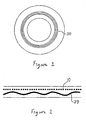
- the upper or radially outer portion of the portion 2 forms a portion 5 adapted to the rim hook. This portion is often curved axially outwards, as illustrated in FIG. figure 1 .
- the portion 2 terminates radially and axially inwardly by a bead seat, adapted to be disposed against a rim seat.
- the bead also comprises an axially inner portion 3, extending substantially radially from the seat to the sidewall 6.
- the tire also comprises a reinforcing structure 10 or reinforcing carcass type provided with reinforcements advantageously configured in a substantially radial arrangement.
- This structure can be arranged continuously from one bead to the other, through the sides and the top of the tire, or it can comprise two or more parts, arranged for example along the sidewalls, without covering the entire summit.
- the tire rigid support for example a rigid core imposing the shape of its inner cavity.
- the core in the order required by the final architecture, are applied all the constituents of the tire, which are placed directly in their final place, without the profile of the tire having to be modified during manufacture.
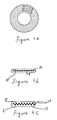
- the anchoring function can be achieved by means of a circumferential yarn arrangement, as illustrated for example in FIG. figure 3b .
- These son are preferably metal, and possibly brass.
- Various variants advantageously provide yarns of textile nature, such as aramid, nylon, PET, PEN, or hybrid. In each stack, the son are advantageously substantially concentric and superimposed.
- a laminated composite bead is produced inside the bead 1, between the wire alignments of the reinforcing structure, there are 21 son oriented circumferentially. These are arranged in a stack 22 as in the figures, or in several adjacent piles, or in any judicious arrangement, depending on the type of tire and / or the desired characteristics.
- the radially inner end portions of the reinforcing structure 10 cooperate with the wire windings. An anchoring of these portions is thus created in said beads.
- the space between the circumferential threads and the reinforcing structure is occupied by a rubber bonding or bonding mixture 60.
- the modulus of elasticity of such a mixture can reach or exceed 10 to 15 MPa, and even in some cases reach or exceed 40 MPa.
- Wire arrangements can be arranged and manufactured in many ways.
- a battery may advantageously consist of a single wire wound (substantially zero degrees) spirally over several turns, preferably from the smallest diameter to the largest diameter.
- a stack may also consist of several concentric threads placed one inside the other, so that one is superimposed rings of progressively increasing diameter. It is not necessary to add a rubber mixture to ensure the impregnation of the reinforcing thread, or circumferential windings of thread.
- FIGS. 1 and 2 illustrate two first preferred embodiments according to the invention.
- at least one circumferential wire 30 is disposed in the sidewall. It is advantageously son of substantially elastic type. These are preferably arranged in the substantially median portion of the flanks. In general this portion corresponds to the section of the flanks of greater width.
- the one or more circumferential threads are of bi-module type.
- a first module (from 0.2 to 2 GPa), for normal operation, to obtain properties similar to good standard tires, with good characteristics including comfort and rolling resistance.
- a second module (20 to 100 GPa), appears when the flanks are collapsed and the circumferential yarns are subjected to significant elongation / stretching stresses, allowing stiffening of the flanks and supporting the load induced by the loss. pressure.
- the circumferential threads are preferably effective in the second case, and interfere little or not with the qualities of the tire used at substantially normal pressure.
- the percentage of preferential elongation corresponding to a change of modular characteristic is between 1 and 4%, and preferably between 2 and 3%.
- the elasticity of the son is obtained thanks to a specific configuration of the cables.
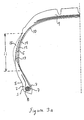
- the circumferential yarns are disposed along the circumference of the tire with circumferential corrugations.
- the wires do not always occupy the same axial position depending on the angular position on the sidewall.
- these substantially parallel wires are used, these are preferably corrugated so as to follow similar paths.
- the threads are sometimes more inward, sometimes more outwardly, forming waves or waves extending circumferentially along the flanks.
- These corrugations are advantageously similar (wavelengths, amplitudes, etc., comparable) to those of the wires of the carcass-type reinforcement structure (as described below).
- the corrugations of these two types of elements are advantageously in phase, so as to substantially correspond along their respective paths.
- the figure 7 shows an example of such a circumferential wire 30 with corrugations, presented in a perspective view according to the three traditional axes, to better visualize said undulations.
- the undulations may be weaker than those shown in this figure.
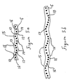
- FIGS. 3a and 3b illustrate an advantageous variant of the invention having different possible paths for the carcass-type reinforcing structure 10.
- a flank zone with corrugations 11 extends radially in the side between the bead 1 and the crown zone 9. Out of this zone, all carcass-type structure wires occupy a substantially identical radial position in the sidewall. But in this zone 11, the different son distributed along the sidewall do not all occupy the same radial position. This is clearly visible on Figures 4c , 5a and 5b in addition to figure 3b .
- the various possible positions lie between a path of the most axially inner reinforcing structure 12 and a path of the most axially outer reinforcing structure 13 (in dotted line).
- the Figure 4b and 4c illustrate well the shades or variations of axial positions of the reinforcing structure son in the sidewall, depending on the radial position in the latter.
- the figure 4b shows a substantially linear arrangement of the yarns in the sidewall, insofar as the yarns are observed outside the corrugated zone, as for example at the radial positions BB 'illustrated in FIG. figure 4a .
- the figure 4c shows the same son at a radial position corresponding substantially to the corrugated area, such as the radial position AA 'illustrated in FIG. figure 4a .
- the zone AA ' is therefore included in the corrugated zone 11 or multi-position interval.
- FIGs 6a and 6b illustrate the influence of the angular position of a tire according to the invention with respect to the ground 300, on the dynamic evolutions of the shape and the amplitude of the corrugations.
- the flank undergoes a mechanical stress tending to stretch, stretch or straighten the corrugations, as illustrated in FIG. figure 6b for the AA 'profile in dotted lines, corresponding to the AA' section of the figure 6a .
- the figure 6b shows also, in solid lines, the profile B-B ', with the undulations, corresponding to the section BB' of the figure 6a , that is to say in an area not under the influence of the contact area.
- the corrugations provide a kind of "reserve" of material, available to respond to the various mechanical stresses due to deformations at the passage in the contact area, and in particular the circumferential stresses.
- This reserve available reduces or may even in some cases avoid the use of stretching rubber mix between the son.
- the mechanical stresses due to the contact area are thus somehow damped or absorbed by the corrugations of the flanks. This deformation is achieved with a substantially limited heating compared to stretching the rubber mix. The rolling resistance and endurance characteristics are therefore not affected.
- the wires 30 have a similar behavior, so that their undulations also flatten out, until the wires become more and more subject to circumferential tension forces.
- the circumferential cords put in tension generate a substantially progressive blocking of the buckling of the flanks.
- these wires have a flank support effect, which can no longer collapse.
- the sidewalls can therefore support or withstand the forces, a little like a self-supporting tire, but with support due to a circumferentially acting element rather than radially.
- This progressive circumferential locking phenomenon thus makes it possible to have distinct situations: in normal pressure mode, with the corrugations of the circumferential threads and the threads of the carcass-type reinforcement structure, the flanks are substantially flexible; in low pressure mode, with increasing attenuation of the two types of corrugations in the portion of the tire corresponding substantially to the area of contact with the ground, the stiffening of the sidewalls allows for a self-porting function.
- flank support means is a bi-module cable
- the effect is comparable, except that the elasticity is conferred by the circumferential cables rather than by the corrugations.
- the industrial manufacture of a tire according to the invention can be carried out according to several types of processes.
- a principle of laying on a central core is used allowing either the individual laying of the constituent elements such as rubber mixes and reinforcements (son) or the laying of semi-finished products such as rubber reinforced lamellae.
- a central core is used provided with corrugations in the zone corresponding substantially to the zone 11 of the tire, thus making it possible to confer, as soon as the various elements are laid, the corrugated shape or profile of the flanks, as previously described. .
Landscapes
- Engineering & Computer Science (AREA)
- Mechanical Engineering (AREA)
- Tires In General (AREA)
- Prostheses (AREA)
- Materials For Medical Uses (AREA)
Applications Claiming Priority (3)
| Application Number | Priority Date | Filing Date | Title |
|---|---|---|---|
| FR0216749 | 2002-12-26 | ||
| FR0216749 | 2002-12-26 | ||
| PCT/EP2003/012925 WO2004058516A1 (fr) | 2002-12-26 | 2003-11-19 | Pneumatique a mobilite etendue avec flancs a rigidite variable |
Publications (2)
| Publication Number | Publication Date |
|---|---|
| EP1578620A1 EP1578620A1 (fr) | 2005-09-28 |
| EP1578620B1 true EP1578620B1 (fr) | 2008-09-17 |
Family
ID=32669142
Family Applications (1)
| Application Number | Title | Priority Date | Filing Date |
|---|---|---|---|
| EP03779985A Expired - Lifetime EP1578620B1 (fr) | 2002-12-26 | 2003-11-19 | Pneumatique a mobilite etendue avec flancs a rigidite variable |
Country Status (9)
| Country | Link |
|---|---|
| US (1) | US7281558B2 (ko) |
| EP (1) | EP1578620B1 (ko) |
| JP (1) | JP4522865B2 (ko) |
| KR (1) | KR20050084491A (ko) |
| CN (1) | CN1729110B (ko) |
| AT (1) | ATE408526T1 (ko) |
| AU (1) | AU2003288113A1 (ko) |
| DE (1) | DE60323675D1 (ko) |
| WO (1) | WO2004058516A1 (ko) |
Families Citing this family (8)
| Publication number | Priority date | Publication date | Assignee | Title |
|---|---|---|---|---|
| CN1714003B (zh) * | 2002-11-18 | 2011-08-24 | 米其林技术公司 | 带有波状侧壁的扩展移动性轮胎 |
| FR2886580B1 (fr) * | 2005-06-02 | 2008-01-04 | Michelin Soc Tech | Pneumatique avec flanc ondules |
| PL2531360T3 (pl) | 2010-02-01 | 2015-03-31 | Galileo Wheel Ltd | Odkształcalny zespół kołowy |
| LT2736737T (lt) * | 2011-07-27 | 2018-03-26 | Galileo Wheel Ltd. | Padanga antžeminio transporto priemonei |
| JP5261584B2 (ja) * | 2012-01-20 | 2013-08-14 | 住友ゴム工業株式会社 | 空気入りタイヤの製造方法 |
| WO2014201368A1 (en) | 2013-06-15 | 2014-12-18 | Ronald Thompson | Annular ring and non-pneumatic tire |
| CA2976055A1 (en) | 2015-02-04 | 2016-08-11 | Advancing Mobility, Llc. | Non-pneumatic tire and other annular devices |
| US10442252B2 (en) * | 2015-04-09 | 2019-10-15 | Jeffrey P Douglas | Tire with high strength corrugated sidewalls |
Family Cites Families (24)
| Publication number | Priority date | Publication date | Assignee | Title |
|---|---|---|---|---|
| US3240250A (en) * | 1964-06-11 | 1966-03-15 | Nat Standard Co | Pneumatic tires |
| NL130258C (ko) * | 1965-07-28 | |||
| BE794658A (fr) * | 1972-02-03 | 1973-07-30 | Michelin & Cie | Perfectionnements aux enveloppes de pneumatiques |
| JPS52106504A (en) | 1976-03-04 | 1977-09-07 | Bridgestone Corp | Radial pneumatic tire for rough ground having superior side cut resist ability |
| US4436139A (en) * | 1981-07-20 | 1984-03-13 | Motor Wheel Corporation | Method and apparatus for manufacture of brake drums |
| JPH02234812A (ja) * | 1989-03-08 | 1990-09-18 | Bridgestone Corp | 空気入りタイヤ |
| US5660656A (en) * | 1992-08-05 | 1997-08-26 | Sedepro | Tire with anchored carcass |
| JPH06340209A (ja) * | 1993-06-01 | 1994-12-13 | Bridgestone Corp | 建設車両用空気入りラジアルタイヤ |
| JP2643085B2 (ja) * | 1994-02-09 | 1997-08-20 | 住友ゴム工業株式会社 | 空気入りタイヤ及びその製造方法 |
| JPH09193625A (ja) * | 1996-01-17 | 1997-07-29 | Bridgestone Corp | 空気入りタイヤ |
| JP3665884B2 (ja) * | 1996-08-05 | 2005-06-29 | 東洋ゴム工業株式会社 | 空気入りラジアルタイヤ |
| JP3418519B2 (ja) * | 1997-02-20 | 2003-06-23 | 不二精工株式会社 | 空気入りラジアルタイヤ |
| US6279630B1 (en) * | 1998-12-23 | 2001-08-28 | Daimlerchrysler Ag | Non pneumatic tires |
| US6695025B1 (en) * | 1999-05-18 | 2004-02-24 | The Goodyear Tire & Rubber Company | Runflat tire construction with ply cords having a variable modulus of elasticity |
| KR20010053607A (ko) * | 1999-05-27 | 2001-06-25 | 폴 겔리 | 최적화된 카카스 경로를 구비한 런플랫 타이어 |
| JP3449692B2 (ja) * | 1999-09-24 | 2003-09-22 | 不二精工株式会社 | 空気入りラジアルタイヤ |
| US6453961B1 (en) * | 2000-06-01 | 2002-09-24 | The Goodyear Tire & Rubber Company | Variable-stiffness wedge insert for runflat tire |
| JP4820525B2 (ja) * | 2000-07-31 | 2011-11-24 | ソシエテ ド テクノロジー ミシュラン | 防振手段を備えた二輪車用タイヤ |
| JP4537561B2 (ja) * | 2000-09-28 | 2010-09-01 | 住友ゴム工業株式会社 | 空気入りタイヤ |
| WO2002030691A1 (en) * | 2000-10-10 | 2002-04-18 | Societe De Technologie Michelin | Tire having more carcass layers in sidewall than in bead |
| WO2002030688A1 (en) * | 2000-10-10 | 2002-04-18 | Societe De Technologie Michelin | Tire having an outer carcass path |
| EP1446279B1 (en) * | 2001-11-22 | 2006-03-01 | PIRELLI PNEUMATICI Società per Azioni | Vehicle tyre provided with sidewall reinforcements. |
| JP2003231406A (ja) * | 2002-02-12 | 2003-08-19 | Yokohama Rubber Co Ltd:The | 空気入りタイヤ |
| CN1714003B (zh) * | 2002-11-18 | 2011-08-24 | 米其林技术公司 | 带有波状侧壁的扩展移动性轮胎 |
-
2003
- 2003-11-19 AU AU2003288113A patent/AU2003288113A1/en not_active Abandoned
- 2003-11-19 EP EP03779985A patent/EP1578620B1/fr not_active Expired - Lifetime
- 2003-11-19 KR KR1020057011951A patent/KR20050084491A/ko not_active Application Discontinuation
- 2003-11-19 DE DE60323675T patent/DE60323675D1/de not_active Expired - Lifetime
- 2003-11-19 AT AT03779985T patent/ATE408526T1/de not_active IP Right Cessation
- 2003-11-19 CN CN2003801072774A patent/CN1729110B/zh not_active Expired - Fee Related
- 2003-11-19 WO PCT/EP2003/012925 patent/WO2004058516A1/fr active IP Right Grant
- 2003-11-19 JP JP2004562551A patent/JP4522865B2/ja not_active Expired - Fee Related
-
2005
- 2005-06-24 US US11/165,351 patent/US7281558B2/en not_active Expired - Fee Related
Also Published As
| Publication number | Publication date |
|---|---|
| CN1729110B (zh) | 2010-10-13 |
| EP1578620A1 (fr) | 2005-09-28 |
| US7281558B2 (en) | 2007-10-16 |
| ATE408526T1 (de) | 2008-10-15 |
| JP4522865B2 (ja) | 2010-08-11 |
| JP2006512243A (ja) | 2006-04-13 |
| CN1729110A (zh) | 2006-02-01 |
| KR20050084491A (ko) | 2005-08-26 |
| AU2003288113A1 (en) | 2004-07-22 |
| WO2004058516A1 (fr) | 2004-07-15 |
| DE60323675D1 (de) | 2008-10-30 |
| US20050236086A1 (en) | 2005-10-27 |
Similar Documents
| Publication | Publication Date | Title |
|---|---|---|
| EP3568289B1 (fr) | Assemblage comprenant une structure élastique et une structure porteuse | |
| EP3568290B1 (fr) | Assemblage comprenant un tissu partiellement rompable et une structure porteuse | |
| EP3390114B1 (fr) | Ensemble pour pneumatique comprenant des tissu(s) ou tricot(s) imprégnés et un moyen de maintien sacrificiel | |
| EP3568291B1 (fr) | Assemblage pour pneumatique comprenant une structure rompable et une structure porteuse, pneumatique et procédé de fabrication dudit pneu | |
| EP1237739B1 (fr) | Bourrelet pour pneumatique a mobilite etendue | |
| EP1565328B1 (fr) | Pneumatique a mobilite etendue avec flancs ondules | |
| EP1254034B1 (fr) | Bourrelet pour pneumatique a mobilite etendue | |
| EP1578620B1 (fr) | Pneumatique a mobilite etendue avec flancs a rigidite variable | |
| EP1395448B1 (fr) | Pneumatique avec nappe carcasse a bi-ancrage | |
| EP1461215B1 (fr) | Pneumatique avec demi-carcasses doubles et zone sommet adaptee | |
| EP2331350B1 (fr) | Pneumatique pour vehicules lourds comportant au moins dans chaque epaule au moins deux couches additionnelles dans l'armature de sommet | |
| EP1789266B1 (fr) | Pneumatique a mobilite etendue avec zone d'ancrage surabaissee | |
| WO2006024561A1 (fr) | Pneumatique a mobilite etendue avec zone d'ancrage a moment d'inertie eleve | |
| EP1554133B1 (fr) | Pneumatique a mobilite etendue avec bourrelet a repartition d'effort symetrique | |
| WO2002000451A1 (fr) | Pneumatique avec demi-carcasses doubles | |
| EP1893421B1 (fr) | Pneumatique avec flancs ondules | |
| EP1534542A1 (fr) | Pneumatique avec ancrage non-lineaire de structure de renfort | |
| EP1101633B1 (fr) | Pneumatique avec zone basse découplée | |
| EP1663672B1 (fr) | Pneumatique a mobilite etendue avec bourrelets agences de facon asymetrique | |
| WO2003093034A2 (fr) | Pneumatique avec bourrelet muni dune structure filaire repartie en deux zones | |
| WO2002000455A1 (fr) | Renfort lateral pour pneumatique | |
| WO2003093032A1 (fr) | Pneumatique avec bourrelet dont la zone d'ancrage est microdeformable | |
| WO2003093033A1 (fr) | Pneumatique avec bourrelet muni d'une zone favorisant le montage/demontage |
Legal Events
| Date | Code | Title | Description |
|---|---|---|---|
| PUAI | Public reference made under article 153(3) epc to a published international application that has entered the european phase |
Free format text: ORIGINAL CODE: 0009012 |
|
| 17P | Request for examination filed |
Effective date: 20050726 |
|
| AK | Designated contracting states |
Kind code of ref document: A1 Designated state(s): AT BE BG CH CY CZ DE DK EE ES FI FR GB GR HU IE IT LI LU MC NL PT RO SE SI SK TR |
|
| AX | Request for extension of the european patent |
Extension state: AL LT LV MK |
|
| DAX | Request for extension of the european patent (deleted) | ||
| 17Q | First examination report despatched |
Effective date: 20071129 |
|
| GRAP | Despatch of communication of intention to grant a patent |
Free format text: ORIGINAL CODE: EPIDOSNIGR1 |
|
| GRAS | Grant fee paid |
Free format text: ORIGINAL CODE: EPIDOSNIGR3 |
|
| GRAA | (expected) grant |
Free format text: ORIGINAL CODE: 0009210 |
|
| AK | Designated contracting states |
Kind code of ref document: B1 Designated state(s): AT BE BG CH CY CZ DE DK EE ES FI FR GB GR HU IE IT LI LU MC NL PT RO SE SI SK TR |
|
| REG | Reference to a national code |
Ref country code: GB Ref legal event code: FG4D Free format text: NOT ENGLISH |
|
| REG | Reference to a national code |
Ref country code: CH Ref legal event code: EP |
|
| REG | Reference to a national code |
Ref country code: IE Ref legal event code: FG4D Free format text: LANGUAGE OF EP DOCUMENT: FRENCH |
|
| REF | Corresponds to: |
Ref document number: 60323675 Country of ref document: DE Date of ref document: 20081030 Kind code of ref document: P |
|
| PG25 | Lapsed in a contracting state [announced via postgrant information from national office to epo] |
Ref country code: AT Free format text: LAPSE BECAUSE OF FAILURE TO SUBMIT A TRANSLATION OF THE DESCRIPTION OR TO PAY THE FEE WITHIN THE PRESCRIBED TIME-LIMIT Effective date: 20080917 Ref country code: FI Free format text: LAPSE BECAUSE OF FAILURE TO SUBMIT A TRANSLATION OF THE DESCRIPTION OR TO PAY THE FEE WITHIN THE PRESCRIBED TIME-LIMIT Effective date: 20080917 Ref country code: SI Free format text: LAPSE BECAUSE OF FAILURE TO SUBMIT A TRANSLATION OF THE DESCRIPTION OR TO PAY THE FEE WITHIN THE PRESCRIBED TIME-LIMIT Effective date: 20080917 |
|
| NLV1 | Nl: lapsed or annulled due to failure to fulfill the requirements of art. 29p and 29m of the patents act | ||
| REG | Reference to a national code |
Ref country code: IE Ref legal event code: FD4D |
|
| PG25 | Lapsed in a contracting state [announced via postgrant information from national office to epo] |
Ref country code: ES Free format text: LAPSE BECAUSE OF FAILURE TO SUBMIT A TRANSLATION OF THE DESCRIPTION OR TO PAY THE FEE WITHIN THE PRESCRIBED TIME-LIMIT Effective date: 20081228 Ref country code: BG Free format text: LAPSE BECAUSE OF FAILURE TO SUBMIT A TRANSLATION OF THE DESCRIPTION OR TO PAY THE FEE WITHIN THE PRESCRIBED TIME-LIMIT Effective date: 20081217 |
|
| PG25 | Lapsed in a contracting state [announced via postgrant information from national office to epo] |
Ref country code: SK Free format text: LAPSE BECAUSE OF FAILURE TO SUBMIT A TRANSLATION OF THE DESCRIPTION OR TO PAY THE FEE WITHIN THE PRESCRIBED TIME-LIMIT Effective date: 20080917 Ref country code: RO Free format text: LAPSE BECAUSE OF FAILURE TO SUBMIT A TRANSLATION OF THE DESCRIPTION OR TO PAY THE FEE WITHIN THE PRESCRIBED TIME-LIMIT Effective date: 20080917 Ref country code: PT Free format text: LAPSE BECAUSE OF FAILURE TO SUBMIT A TRANSLATION OF THE DESCRIPTION OR TO PAY THE FEE WITHIN THE PRESCRIBED TIME-LIMIT Effective date: 20090217 Ref country code: NL Free format text: LAPSE BECAUSE OF FAILURE TO SUBMIT A TRANSLATION OF THE DESCRIPTION OR TO PAY THE FEE WITHIN THE PRESCRIBED TIME-LIMIT Effective date: 20080917 Ref country code: CZ Free format text: LAPSE BECAUSE OF FAILURE TO SUBMIT A TRANSLATION OF THE DESCRIPTION OR TO PAY THE FEE WITHIN THE PRESCRIBED TIME-LIMIT Effective date: 20080917 |
|
| BERE | Be: lapsed |
Owner name: MICHELIN RECHERCHE ET TECHNIQUE S.A. Effective date: 20081130 Owner name: SOC. DE TECHNOLOGIE MICHELIN Effective date: 20081130 |
|
| PG25 | Lapsed in a contracting state [announced via postgrant information from national office to epo] |
Ref country code: MC Free format text: LAPSE BECAUSE OF NON-PAYMENT OF DUE FEES Effective date: 20081130 |
|
| REG | Reference to a national code |
Ref country code: CH Ref legal event code: PL |
|
| PLBE | No opposition filed within time limit |
Free format text: ORIGINAL CODE: 0009261 |
|
| STAA | Information on the status of an ep patent application or granted ep patent |
Free format text: STATUS: NO OPPOSITION FILED WITHIN TIME LIMIT |
|
| PG25 | Lapsed in a contracting state [announced via postgrant information from national office to epo] |
Ref country code: DK Free format text: LAPSE BECAUSE OF FAILURE TO SUBMIT A TRANSLATION OF THE DESCRIPTION OR TO PAY THE FEE WITHIN THE PRESCRIBED TIME-LIMIT Effective date: 20080917 Ref country code: IE Free format text: LAPSE BECAUSE OF FAILURE TO SUBMIT A TRANSLATION OF THE DESCRIPTION OR TO PAY THE FEE WITHIN THE PRESCRIBED TIME-LIMIT Effective date: 20080917 Ref country code: EE Free format text: LAPSE BECAUSE OF FAILURE TO SUBMIT A TRANSLATION OF THE DESCRIPTION OR TO PAY THE FEE WITHIN THE PRESCRIBED TIME-LIMIT Effective date: 20080917 |
|
| 26N | No opposition filed |
Effective date: 20090618 |
|
| GBPC | Gb: european patent ceased through non-payment of renewal fee |
Effective date: 20081217 |
|
| PG25 | Lapsed in a contracting state [announced via postgrant information from national office to epo] |
Ref country code: BE Free format text: LAPSE BECAUSE OF NON-PAYMENT OF DUE FEES Effective date: 20081130 |
|
| PG25 | Lapsed in a contracting state [announced via postgrant information from national office to epo] |
Ref country code: CH Free format text: LAPSE BECAUSE OF NON-PAYMENT OF DUE FEES Effective date: 20081130 Ref country code: LI Free format text: LAPSE BECAUSE OF NON-PAYMENT OF DUE FEES Effective date: 20081130 |
|
| PG25 | Lapsed in a contracting state [announced via postgrant information from national office to epo] |
Ref country code: GB Free format text: LAPSE BECAUSE OF NON-PAYMENT OF DUE FEES Effective date: 20081217 |
|
| PG25 | Lapsed in a contracting state [announced via postgrant information from national office to epo] |
Ref country code: SE Free format text: LAPSE BECAUSE OF FAILURE TO SUBMIT A TRANSLATION OF THE DESCRIPTION OR TO PAY THE FEE WITHIN THE PRESCRIBED TIME-LIMIT Effective date: 20081217 |
|
| PG25 | Lapsed in a contracting state [announced via postgrant information from national office to epo] |
Ref country code: HU Free format text: LAPSE BECAUSE OF FAILURE TO SUBMIT A TRANSLATION OF THE DESCRIPTION OR TO PAY THE FEE WITHIN THE PRESCRIBED TIME-LIMIT Effective date: 20090318 Ref country code: CY Free format text: LAPSE BECAUSE OF FAILURE TO SUBMIT A TRANSLATION OF THE DESCRIPTION OR TO PAY THE FEE WITHIN THE PRESCRIBED TIME-LIMIT Effective date: 20080917 Ref country code: LU Free format text: LAPSE BECAUSE OF NON-PAYMENT OF DUE FEES Effective date: 20081119 |
|
| PG25 | Lapsed in a contracting state [announced via postgrant information from national office to epo] |
Ref country code: TR Free format text: LAPSE BECAUSE OF FAILURE TO SUBMIT A TRANSLATION OF THE DESCRIPTION OR TO PAY THE FEE WITHIN THE PRESCRIBED TIME-LIMIT Effective date: 20080917 |
|
| PG25 | Lapsed in a contracting state [announced via postgrant information from national office to epo] |
Ref country code: GR Free format text: LAPSE BECAUSE OF FAILURE TO SUBMIT A TRANSLATION OF THE DESCRIPTION OR TO PAY THE FEE WITHIN THE PRESCRIBED TIME-LIMIT Effective date: 20081218 |
|
| PGFP | Annual fee paid to national office [announced via postgrant information from national office to epo] |
Ref country code: FR Payment date: 20121130 Year of fee payment: 10 Ref country code: DE Payment date: 20121121 Year of fee payment: 10 |
|
| PGFP | Annual fee paid to national office [announced via postgrant information from national office to epo] |
Ref country code: IT Payment date: 20121127 Year of fee payment: 10 |
|
| REG | Reference to a national code |
Ref country code: DE Ref legal event code: R119 Ref document number: 60323675 Country of ref document: DE |
|
| REG | Reference to a national code |
Ref country code: FR Ref legal event code: ST Effective date: 20140731 |
|
| PG25 | Lapsed in a contracting state [announced via postgrant information from national office to epo] |
Ref country code: DE Free format text: LAPSE BECAUSE OF NON-PAYMENT OF DUE FEES Effective date: 20140603 Ref country code: IT Free format text: LAPSE BECAUSE OF NON-PAYMENT OF DUE FEES Effective date: 20131119 |
|
| REG | Reference to a national code |
Ref country code: DE Ref legal event code: R119 Ref document number: 60323675 Country of ref document: DE Effective date: 20140603 |
|
| PG25 | Lapsed in a contracting state [announced via postgrant information from national office to epo] |
Ref country code: FR Free format text: LAPSE BECAUSE OF NON-PAYMENT OF DUE FEES Effective date: 20131202 |