EP1578620B1 - Run-flat tyre with variable-rigidity sidewalls - Google Patents
Run-flat tyre with variable-rigidity sidewalls Download PDFInfo
- Publication number
- EP1578620B1 EP1578620B1 EP03779985A EP03779985A EP1578620B1 EP 1578620 B1 EP1578620 B1 EP 1578620B1 EP 03779985 A EP03779985 A EP 03779985A EP 03779985 A EP03779985 A EP 03779985A EP 1578620 B1 EP1578620 B1 EP 1578620B1
- Authority
- EP
- European Patent Office
- Prior art keywords
- tire
- circumferential
- sidewall
- sidewalls
- reinforcement structure
- Prior art date
- Legal status (The legal status is an assumption and is not a legal conclusion. Google has not performed a legal analysis and makes no representation as to the accuracy of the status listed.)
- Expired - Lifetime
Links
- 230000000750 progressive effect Effects 0.000 claims abstract description 7
- 230000001747 exhibiting effect Effects 0.000 claims abstract 2
- 230000002787 reinforcement Effects 0.000 claims description 43
- 239000011324 bead Substances 0.000 claims description 32
- 238000004873 anchoring Methods 0.000 claims description 16
- 230000000717 retained effect Effects 0.000 claims 1
- 230000003014 reinforcing effect Effects 0.000 description 22
- 239000000203 mixture Substances 0.000 description 18
- 238000000034 method Methods 0.000 description 14
- 230000006870 function Effects 0.000 description 8
- 238000005096 rolling process Methods 0.000 description 7
- 238000004519 manufacturing process Methods 0.000 description 6
- 230000008569 process Effects 0.000 description 6
- 239000011265 semifinished product Substances 0.000 description 6
- 208000002740 Muscle Rigidity Diseases 0.000 description 5
- 230000000694 effects Effects 0.000 description 5
- 239000000047 product Substances 0.000 description 5
- 230000000712 assembly Effects 0.000 description 3
- 238000000429 assembly Methods 0.000 description 3
- 230000000903 blocking effect Effects 0.000 description 3
- 238000005516 engineering process Methods 0.000 description 3
- 239000000463 material Substances 0.000 description 3
- 238000004804 winding Methods 0.000 description 3
- 230000008901 benefit Effects 0.000 description 2
- 230000008859 change Effects 0.000 description 2
- 239000011248 coating agent Substances 0.000 description 2
- 238000000576 coating method Methods 0.000 description 2
- 239000000470 constituent Substances 0.000 description 2
- 238000007796 conventional method Methods 0.000 description 2
- 230000002349 favourable effect Effects 0.000 description 2
- 238000010438 heat treatment Methods 0.000 description 2
- 238000012423 maintenance Methods 0.000 description 2
- 238000007665 sagging Methods 0.000 description 2
- 238000004381 surface treatment Methods 0.000 description 2
- 238000011282 treatment Methods 0.000 description 2
- 229910001369 Brass Inorganic materials 0.000 description 1
- 239000004677 Nylon Substances 0.000 description 1
- 241001080024 Telles Species 0.000 description 1
- 230000009471 action Effects 0.000 description 1
- 238000004026 adhesive bonding Methods 0.000 description 1
- 239000004760 aramid Substances 0.000 description 1
- 229920003235 aromatic polyamide Polymers 0.000 description 1
- 230000002238 attenuated effect Effects 0.000 description 1
- 239000010951 brass Substances 0.000 description 1
- 230000015556 catabolic process Effects 0.000 description 1
- 239000002131 composite material Substances 0.000 description 1
- 150000001875 compounds Chemical class 0.000 description 1
- 238000013461 design Methods 0.000 description 1
- 238000011161 development Methods 0.000 description 1
- 230000018109 developmental process Effects 0.000 description 1
- 239000013536 elastomeric material Substances 0.000 description 1
- 231100001261 hazardous Toxicity 0.000 description 1
- 238000005470 impregnation Methods 0.000 description 1
- 238000005304 joining Methods 0.000 description 1
- 239000002184 metal Substances 0.000 description 1
- 230000007935 neutral effect Effects 0.000 description 1
- 229920001778 nylon Polymers 0.000 description 1
- 229920003207 poly(ethylene-2,6-naphthalate) Polymers 0.000 description 1
- 239000011112 polyethylene naphthalate Substances 0.000 description 1
- 229920000139 polyethylene terephthalate Polymers 0.000 description 1
- 239000005020 polyethylene terephthalate Substances 0.000 description 1
- 239000011148 porous material Substances 0.000 description 1
- 238000004513 sizing Methods 0.000 description 1
- 239000000126 substance Substances 0.000 description 1
- 239000004753 textile Substances 0.000 description 1
- 238000004073 vulcanization Methods 0.000 description 1
Images


Classifications
-
- B—PERFORMING OPERATIONS; TRANSPORTING
- B60—VEHICLES IN GENERAL
- B60C—VEHICLE TYRES; TYRE INFLATION; TYRE CHANGING; CONNECTING VALVES TO INFLATABLE ELASTIC BODIES IN GENERAL; DEVICES OR ARRANGEMENTS RELATED TO TYRES
- B60C13/00—Tyre sidewalls; Protecting, decorating, marking, or the like, thereof
-
- B—PERFORMING OPERATIONS; TRANSPORTING
- B60—VEHICLES IN GENERAL
- B60C—VEHICLE TYRES; TYRE INFLATION; TYRE CHANGING; CONNECTING VALVES TO INFLATABLE ELASTIC BODIES IN GENERAL; DEVICES OR ARRANGEMENTS RELATED TO TYRES
- B60C9/00—Reinforcements or ply arrangement of pneumatic tyres
- B60C9/02—Carcasses
- B60C9/04—Carcasses the reinforcing cords of each carcass ply arranged in a substantially parallel relationship
- B60C9/08—Carcasses the reinforcing cords of each carcass ply arranged in a substantially parallel relationship the cords extend transversely from bead to bead, i.e. radial ply
- B60C9/09—Carcasses the reinforcing cords of each carcass ply arranged in a substantially parallel relationship the cords extend transversely from bead to bead, i.e. radial ply combined with other carcass plies having cords extending diagonally from bead to bead, i.e. combined radial ply and bias angle ply
-
- Y—GENERAL TAGGING OF NEW TECHNOLOGICAL DEVELOPMENTS; GENERAL TAGGING OF CROSS-SECTIONAL TECHNOLOGIES SPANNING OVER SEVERAL SECTIONS OF THE IPC; TECHNICAL SUBJECTS COVERED BY FORMER USPC CROSS-REFERENCE ART COLLECTIONS [XRACs] AND DIGESTS
- Y10—TECHNICAL SUBJECTS COVERED BY FORMER USPC
- Y10T—TECHNICAL SUBJECTS COVERED BY FORMER US CLASSIFICATION
- Y10T152/00—Resilient tires and wheels
- Y10T152/10—Tires, resilient
- Y10T152/10495—Pneumatic tire or inner tube
- Y10T152/10819—Characterized by the structure of the bead portion of the tire
-
- Y—GENERAL TAGGING OF NEW TECHNOLOGICAL DEVELOPMENTS; GENERAL TAGGING OF CROSS-SECTIONAL TECHNOLOGIES SPANNING OVER SEVERAL SECTIONS OF THE IPC; TECHNICAL SUBJECTS COVERED BY FORMER USPC CROSS-REFERENCE ART COLLECTIONS [XRACs] AND DIGESTS
- Y10—TECHNICAL SUBJECTS COVERED BY FORMER USPC
- Y10T—TECHNICAL SUBJECTS COVERED BY FORMER US CLASSIFICATION
- Y10T152/00—Resilient tires and wheels
- Y10T152/10—Tires, resilient
- Y10T152/10495—Pneumatic tire or inner tube
- Y10T152/10855—Characterized by the carcass, carcass material, or physical arrangement of the carcass materials
- Y10T152/10864—Sidewall stiffening or reinforcing means other than main carcass plies or foldups thereof about beads
Landscapes
- Engineering & Computer Science (AREA)
- Mechanical Engineering (AREA)
- Tires In General (AREA)
- Prostheses (AREA)
- Materials For Medical Uses (AREA)
Abstract
Description
La présente invention concerne les pneumatiques. Plus particulièrement, elle concerne un pneumatique comportant un agencement particulier des éléments architecturaux disposés dans la zone des flancs, permettant, d'une part, en condition de pression sensiblement normale, l'obtention de flancs souples, susceptibles de conférer des qualités, notamment de confort et de résistance au roulement, particulièrement favorables, et d'autre part, en condition de pression réduite, l'obtention de flancs rigidifiés, susceptibles de permettre de supporter la charge du pneumatique, en respectant certaines limites.The present invention relates to tires. More particularly, it relates to a tire comprising a particular arrangement of architectural elements arranged in the zone of the sidewalls, allowing, on the one hand, in a condition of substantially normal pressure, to obtain flexible sidewalls, capable of conferring qualities, particularly of comfort and rolling resistance, particularly favorable, and secondly, under reduced pressure conditions, obtaining stiffened sidewalls, capable of supporting the load of the tire, within certain limits.
Depuis quelques années, les manufacturiers de pneumatiques consentent des efforts particulièrement importants afin de développer des solutions originales à un problème datant du début même de l'utilisation des roues chaussées de pneus de type gonflés, à savoir comment permettre au véhicule de poursuivre sa route malgré une perte importante ou totale de pression d'un ou plusieurs pneumatiques. Pendant des décennies, la roue de secours fut considérée comme la solution unique et universelle. Puis, plus récemment, les avantages considérables liés à sa suppression éventuelle sont apparus. Le concept de « mobilité étendue » se développe. Les techniques associées permettent de rouler avec le même pneumatique, en fonction de certaines limites à respecter, après une crevaison ou une chute de pression. Cela permet par exemple de se rendre à un point de dépannage sans devoir s'arrêter, dans des circonstances souvent hasardeuses, pour installer la roue de secours.In recent years, tire manufacturers have been making particularly important efforts to develop original solutions to a problem dating back to the very beginning of the use of tires with inflated type tires, namely how to allow the vehicle to continue its journey despite a significant or total loss of pressure of one or more tires. For decades, the spare wheel was considered the unique and universal solution. Then, more recently, the considerable benefits of its eventual removal have emerged. The concept of "extended mobility" is developing. The associated techniques make it possible to ride with the same tire, according to certain limits to be respected, after a puncture or a pressure drop. This allows for example to get to a breakdown point without having to stop, in often hazardous circumstances, to install the spare wheel.
Deux grands types de technologies pour mobilité étendue apparaissent aujourd'hui sur le marché automobile. D'une part, on retrouve les pneumatiques de type autoporteur, (souvent désignés par leur appellation en langue anglaise ZP pour « zero pressure »). Les pneus autoporteurs sont susceptibles de supporter une charge à pression réduite, voire sans pression, grâce à des flancs renforcés, le plus souvent au moyen d'inserts en matière caoutchoutique, prévus dans les flancs. La rigidité structurelle des flancs d'un pneumatique de ce type est très élevée. Les technologies à flancs renforcés privilégient le fonctionnement en mode dégradé, normalement exceptionnel, ou tout au moins très occasionnel pour la grande majorité des véhicules, au détriment du fonctionnement courant, qui subit les inconvénients liés de façon intrinsèque au principe des flancs renforcés. En fonctionnement normal, à la pression nominale d'utilisation, ceci peut entraîner d'importantes pénalisation en terme de résistance au roulement et de confort. Par ailleurs, la forte tendance de la zone basse du pneumatique à vouloir glisser hors de la jante sous l'effet de l'affaissement des flancs peut limiter la portée de cette solution.Two major types of extended mobility technologies are emerging today in the automotive market. On the one hand, we find self-supporting type of tires, (often referred to by their name in the English language ZP for "zero pressure"). The self-supporting tires are likely to withstand a load at reduced pressure or without pressure, thanks to reinforced sidewalls, usually by means of rubber inserts provided in the sidewalls. The structural rigidity of the flanks of a tire of this type is very high. The reinforced sidewall technologies favor the operation in degraded mode, normally exceptional, or at least very occasional for the vast majority of vehicles, to the detriment of the current operation, which undergoes the drawbacks intrinsically linked to the principle of reinforced sidewalls. In normal operation, at the nominal pressure of use, this can lead to significant penalties in terms of rolling resistance and comfort. Moreover, the strong tendency of the low zone of the tire to want to slip out of the rim under the effect of the slump of the flanks may limit the scope of this solution.
Les documents
D'autre part, on retrouve des roues équipées d'appuis, susceptibles de supporter l'intérieur de la bande de roulement d'un pneumatique lors d'un affaissement des flancs suite à une chute de pression. Cette solution est avantageusement couplée à un pneumatique comportant une zone basse susceptible de minimiser les risques de glissement du pneumatique hors de la jante. Cette solution est avantageuse puisqu'elle permet de conserver sensiblement intactes les caractéristiques de roulage en conditions normales. Par contre, elle présente l'inconvénient de nécessiter une pièce additionnelle, l'appui, pour chacune des roues du véhicule.On the other hand, there are wheels equipped with supports, capable of supporting the inside of the tread of a tire during a collapse of the sidewalls following a pressure drop. This solution is advantageously coupled to a tire having a low area which can minimize the risk of sliding of the tire out of the rim. This solution is advantageous since it makes it possible to keep substantially intact the rolling characteristics under normal conditions. On the other hand, it has the disadvantage of requiring an additional piece, the support, for each of the wheels of the vehicle.
Ainsi, afin de pallier ces différents inconvénients, l'invention prévoit un pneumatique comportant au moins une structure de renfort de type carcasse ancrée de chaque côté du pneumatique dans un bourrelet dont la base est destinée à être montée sur un siège de jante, chaque bourrelet se prolongeant radialement vers l'extérieur par un flanc, les flancs rejoignant radialement vers l'extérieur une bande de roulement et comportant au moins un moyen de support de flanc à augmentation de rigidité sensiblement progressive, disposé dans la portion sensiblement médiane desdits flancs, la structure de renfort de type carcasse s'étendant circonférentiellement depuis le bourrelet vers ledit flanc, une armature de sommet, chacun des bourrelets comportant par ailleurs une zone d'ancrage permettant le maintien de la structure de renfort dans chacun desdits bourrelets, ledit moyen de support comporte au moins un fil circonférentiel agencés sur la circonférence suivant des positions axiales différentes, de façon à former le long du parcours circonférentiel, une succession d'ondulations sensiblement régulières formant un profil circonférentiel ondulé.Thus, in order to overcome these various drawbacks, the invention provides a tire comprising at least one carcass-type reinforcement structure anchored on each side of the tire in a bead whose base is intended to be mounted on a rim seat, each bead extending radially outwardly by a sidewall, the flanks joining radially outwardly a tread and having at least one sidewall support means with substantially progressive rigidity increase, disposed in the substantially median portion of said sidewalls, the carcass-type reinforcing structure extending circumferentially from the bead towards said sidewall, a crown reinforcement, each of the beads also comprising an anchoring zone enabling the reinforcement structure to be maintained in each of said beads, said support means has at least one circumferential wire arranged on the circumference according to positio ns different axial, so as to form along the circumferential path, a succession of substantially regular undulations forming a corrugated circumferential profile.
Si l'utilisation d'un enroulement circonférentiel d'un fil en renfort de flanc est connue du documentIf the use of a circumferential winding of a sidewall reinforcement yarn is known from the document
La solution proposée par la présente invention permet de s'affranchir de la plupart des inconvénients liés au techniques actuelles permettant la mobilité étendue. D'une part, le pneumatique ne nécessite pas d'appui pour rouler à faible pression ; d'autre part, il ne dispose pas de flancs rigides renforcés par exemple à l'aide d'inserts en matière caoutchoutique. Les flancs présentent une rigidité structurelle variable avec la flèche du pneumatique. Ainsi, quand le pneu roule avec sa pression nominale, la rigidité structurelle est celle d'un pneu standard. Les flancs présentent une souplesse avantageusement comparable à un pneumatique traditionnel. Les caractéristiques favorables telles qu'un haut niveau de confort, une faible résistance au roulement, une bonne endurance, etc, peuvent être maintenues. Le pneumatique selon l'invention présente ainsi les avantages liés au pneu autoporteur, qui permet d'assurer une mobilité étendue, sans toutefois comporter les inconvénients qui affectent les qualités du pneumatiques en utilisation courante à pression sensiblement normale.The solution proposed by the present invention makes it possible to overcome most of the drawbacks associated with current techniques allowing extended mobility. On the one hand, the tire does not require support to roll at low pressure; on the other hand, it does not have rigid sidewalls reinforced for example with rubber inserts. The sidewalls have a variable structural stiffness with the boom of the tire. Thus, when the tire rolls with its nominal pressure, the structural rigidity is that of a standard tire. The flanks have a flexibility advantageously comparable to a conventional tire. Favorable features such as a high level of comfort, low rolling resistance, good endurance, etc. can be maintained. The tire according to the invention thus has the advantages associated with the self-supporting tire, which makes it possible to ensure extended mobility, without, however, having the disadvantages which affect the qualities of the tires in normal use at a substantially normal pressure.
En mode « mobilité étendue », lorsque la pression chute, la diminution de pression provoque une augmentation de la flèche, et par le fait même, de la rigidité structurelle des flancs : de façon sensiblement progressive, en particulier au niveau de la zone du pneumatique à proximité de l'aire de contact avec le sol, avec l'apparition progressive d'une force de tension de plus en plus grande dans les moyens de support, la rigidité desdits moyens de support augmente. Ces phénomènes entraînent un blocage graduel du flambage des flancs, jusqu'à l'obtention d'une force de soutien susceptible de supporter les efforts transmis par les flancs. On obtient enfin, après mise sous tension des moyens de support, des flancs pouvant supporter la charge. La charge est donc en bonne partie supportée par les moyens de support de flancs. Contrairement aux moyens de type connus, ces moyens, grâce à une action de type circonférentielle, produisent une réaction de type radiale.In "extended mobility" mode, when the pressure drops, the decrease in pressure causes an increase in the deflection, and therefore, the structural stiffness of the flanks: in a substantially progressive manner, in particular at the level of the area of the tire near the area of contact with the ground, with the gradual appearance of a tension force of greater and greater importance in the means of support, the rigidity of said support means increases. These phenomena result in a gradual blocking of flanking flanks, until obtaining a support force capable of withstanding the forces transmitted by the flanks. Finally, after powering the support means, flanks can support the load. The load is therefore largely supported by the flank support means. In contrast to the known type of means, these means, thanks to a circumferential type action, produce a radial type reaction.
Puisque, après étirement des moyens de support dans les flancs, le flambage des flancs est en quelque sorte « bloqué », il ne se produit pas d'affaissement important, voire total, du pneumatique, en particulier au niveau de l'aire de contact. La charge est donc en bonne partie supportée par la mise en tension des moyens de support. Ainsi, avec une pression fortement réduite ou nulle, le pneumatique fonctionne avec une flèche plus importante et une rigidité structurelle considérablement plus élevée, non seulement afin d'empêcher l'affaissement total des flancs, mais également pour permettre de supporter la charge malgré la chute de pression, de façon comparable à un pneu autoporteur.Since, after stretching the support means in the flanks, the flanking of the flanks is in a certain way "blocked", there is no significant or even complete sagging of the tire, in particular at the level of the contact area. . The load is therefore largely supported by the tensioning of the support means. Thus, with a greatly reduced or zero pressure, the tire operates with a greater deflection and a considerably higher structural rigidity, not only to prevent total sagging of the sidewalls, but also to support the load despite the fall. pressure, comparable to a self-supporting tire.
Le ou lesdits fils sont agencés sur la circonférence suivant des positions axiales différentes, de façon à former le long du parcours circonférentiel, une succession d'ondulations sensiblement régulières formant un profil circonférentiel ondulé. II s'agit d'une façon astucieuse et pratique de réaliser la fonction d'élasticité des fils circonférentiels. Dans un tel cas de figure, les fils en tant que tels peuvent être sensiblement rigides. Grâce à l'agencement des fils de façon ondulée, on obtient l'élasticité requise.The one or more yarns are circumferentially arranged at different axial positions, so as to form along the circumferential path a succession of substantially regular corrugations forming a corrugated circumferential profile. This is a clever and practical way of achieving the elasticity function of the circumferential threads. In such a case, the wires as such can be substantially rigid. By arranging the wires in a wavy manner, the required elasticity is obtained.
Selon une variante de réalisation avantageuse, ladite structure de renfort de type carcasse est agencée de façon à ce que, dans la portion sensiblement médiane du flanc, les fils de ladite structure de renfort comportent, sur la circonférence, des positions axiales différentes, de façon à former le long du parcours circonférentiel, une succession d'ondulations sensiblement régulières formant un profil circonférentiel ondulé.According to an advantageous embodiment variant, said carcass-type reinforcement structure is arranged in such a way that, in the substantially median portion of the sidewall, the threads of said reinforcing structure comprise, on the circumference, different axial positions, so as to form along the circumferential path, a succession of substantially regular undulations forming a corrugated circumferential profile.
Selon une variante de réalisation avantageuse, les ondulations formées par lesdits fils circonférentiels d'une part et les ondulations formées par les fils de structure de renfort d'autre part, sont sensiblement en correspondance (sont sensiblement alignées circonférentiellement).According to an advantageous embodiment, the corrugations formed by said circumferential wires on the one hand and the corrugations formed by the reinforcement structure wires on the other hand, are substantially in correspondence (are substantially circumferentially aligned).
En mode « mobilité étendue», lorsque la pression chute, la diminution de pression provoque une augmentation de la flèche, et par le fait même, de la rigidité structurelle des flancs : de façon sensiblement progressive, en particulier au niveau de la zone du pneumatique à proximité de l'aire de contact avec le sol, les ondulations de la structure de renfort de type carcasse s'aplanissent ou s'atténuent ; les ondulations des fils circonférentiels font de même, avec l'apparition progressive d'une force de tension de plus en plus grande dans les fils circonférentiels. Ces phénomènes entraînent un blocage graduel du flambage des flancs, jusqu'à l'obtention d'une force de soutien susceptible de supporter les efforts transmis par les flancs. On obtient enfin, après mise sous tension des fils, des flancs pouvant supporter la charge.In the "extended mobility" mode, when the pressure drops, the decrease in pressure causes an increase in the deflection, and hence the structural stiffness of the sidewalls: substantially progressively, particularly at the level of the tire area near the contact area with the ground, the corrugations of the carcass-type reinforcement structure are flattened or attenuated; the corrugations of the circumferential threads do the same, with the progressive appearance of a tension force of greater and greater importance in the circumferential threads. These phenomena result in a gradual blocking of flanking flanks, until obtaining a support force capable of withstanding the forces transmitted by the flanks. Finally, after energizing the son, flanks can support the load.
Selon un mode de réalisation avantageux de l'invention, la surface extérieure dudit flanc du pneumatique, dans la zone où la structure de renfort comporte lesdites ondulations, comporte également un profil circonférentiel ondulé, sensiblement en correspondance avec ledit profil formé par ladite structure de renfort. On prévoit préférentiellement des ondulations de la position des renfort et de la bordure du flanc d'amplitudes et fréquences sensiblement similaires. On obtient alors une configuration homogène. Par ailleurs, les ondulations de flanc permettent de visualiser les caractéristiques architecturales internes du pneumatique. Ce dernier aspect permet par exemple de mieux identifier ce type de technologie.According to an advantageous embodiment of the invention, the outer surface of said sidewall of the tire, in the zone where the reinforcement structure comprises said corrugations, also comprises a corrugated circumferential profile, substantially in correspondence with said profile formed by said reinforcing structure . The corrugations of the position of the reinforcement and the edge of the flank are preferably provided with amplitudes and frequencies that are substantially similar. This gives a homogeneous configuration. In addition, the side corrugations make it possible to visualize the internal architectural characteristics of the tire. This last aspect makes it possible, for example, to better identify this type of technology.
Selon une variante, la surface extérieure du flanc est sensiblement rectiligne. L'architecture particulière de la structure de renfort n'est donc pas révélée, et le profil du flanc est classiquement configuré.According to one variant, the outer surface of the sidewall is substantially rectilinear. The particular architecture of the reinforcement structure is not revealed, and the profile of the sidewall is conventionally configured.
Les parcours des structures de renfort de type carcasse peuvent être agencés selon deux types de configurations, soit par exemple une configuration « en opposition de phase », dans laquelle la position radiale d'un fil de renfort, pour une position circonférentielle donnée du profil circonférentiel ondulé, est sensiblement symétrique dans chaque flanc par rapport au plan médian dudit pneumatique ; ou une configuration « en phase », dans laquelle, la position radiale d'une portion de structure de renfort, pour une position circonférentielle donnée du profil circonférentiel ondulé, est sensiblement à l'opposée dans chaque flanc.The paths of the carcass-type reinforcement structures can be arranged according to two types of configurations, for example an "in phase opposition" configuration, in which the radial position of a reinforcing wire, for a given circumferential position of the circumferential profile. corrugated, is substantially symmetrical in each side with respect to the median plane of said tire; or an "in-phase" configuration, wherein the radial position of a reinforcing structure portion, for a given circumferential position of the corrugated circumferential profile, is substantially opposite in each flank.
Tous les détails de réalisation sont donnés dans la description qui suit, complétée par les
- la
figure 1 illustre une coupe d'un pneumatique comportant des câbles circonférentiels selon l'invention ; - la
figure 2 illustre une coupe circonférentielle en vue partielle montrant essentiellement un flanc dans lequel un fil circonféntiel est disposé ; - les
figures 3a et3b sont des coupes radiales montrant essentiellement un bourrelet, un flanc, et la moitié du sommet de deux exemples de réalisation d'un premier type de pneumatiques selon l'invention ; - les
figures 4b et 4c sont des coupes circonférentielles en vue partielles montrant essentiellement un flanc avec les positions radiales d'une série de fils de renfort en fonction de leur position radiales dans le flanc telle qu'illustrée à lafigure 4a ; - les
figures 5a et 5b présentent des variantes de réalisation de l'exemple de lafigure 2 ; - la
figure 6b illustre le profil des flancs d'un pneumatique selon l'invention selon une coupe transversale, en différentes positions illustrées à lafigure 6a : en A-A', en « zone étirée » ou « flanc tendu » et en B-B', en zone « flanc ondulé » ; - la
figure 7 illustre une vue en perspective d'un fil de flanc circonférentiel, agencé de façon ondulée.
- the
figure 1 illustrates a section of a tire comprising circumferential cables according to the invention; - the
figure 2 illustrates a circumferential sectional view essentially showing a sidewall in which a circumferential thread is disposed; - the
figures 3a and3b are radial sections essentially showing a bead, a flank, and half the top of two embodiments of a first type of tire according to the invention; - the
Figures 4b and 4c are partial-view circumferential cuts essentially showing a flank with the radial positions of a series of reinforcing threads as a function of their radial position in the sidewall as illustrated in FIG.figure 4a ; - the
Figures 5a and 5b present alternative embodiments of the example of thefigure 2 ; - the
figure 6b illustrates the profile of the sidewalls of a tire according to the invention in a cross-section, in different positions illustrated in FIG.figure 6a : in A-A ', in "stretched zone" or "extended flank" and in B-B', in "corrugated flank"zone; - the
figure 7 illustrates a perspective view of a circumferential sidewall wire, arranged in a wavy manner.
L'armature de renforcement ou renforcement des pneumatiques est à l'heure actuelle - et le plus souvent - constituée par empilage d'une ou plusieurs nappes désignées classiquement « nappes de carcasse », «nappes sommet », etc. Cette façon de désigner les armatures de renforcement provient du procédé de fabrication, consistant à réaliser une série de produits semi-finis en forme de nappes, pourvues de renforts filaires souvent longitudinaux, qui sont par la suite assemblées ou empilées afin de confectionner une ébauche de pneumatique. Les nappes sont réalisées à plat, avec des dimensions importantes, et sont par la suite coupées en fonction des dimensions d'un produit donné. L'assemblage des nappes est également réalisé, dans un premier temps, sensiblement à plat. L'ébauche ainsi réalisée est ensuite mise en forme pour adopter le profil toroïdal typique des pneumatiques. Les produits semi-finis dits « de finition » sont ensuite appliqués sur l'ébauche, pour obtenir un produit prêt pour la vulcanisation.The reinforcement or reinforcement of the tires is at present - and most often - constituted by stacking one or more plies conventionally referred to as "carcass plies", "summit plies", etc. This method of designating reinforcing reinforcements comes from the manufacturing process, consisting in producing a series of semi-finished products in the form of plies, provided with wire reinforcements, often longitudinal, which are subsequently assembled or stacked in order to make a rough draft. pneumatic. Tablecloths are made flat, with large dimensions, and are subsequently cut according to the dimensions of a given product. The assembly of the plies is also made, initially, substantially flat. The blank thus produced is then shaped to adopt the typical toroidal profile of the tires. The so-called "finished" semi-finished products are then applied to the blank to obtain a product ready for vulcanization.
Un tel type de procédé "classique" implique, en particulier pour la phase de fabrication de l'ébauche du pneumatique, l'utilisation d'un élément d'ancrage (généralement une tringle), utilisée pour réaliser l'ancrage ou le maintien de l'armature de carcasse dans la zone des bourrelets du pneumatique. Ainsi, pour ce type de procédé, on effectue un retournement d'une portion de toutes les nappes composant l'armature de carcasse (ou d'une partie seulement) autour d'une tringle disposée dans le bourrelet du pneumatique. On crée de la sorte un ancrage de l'armature de carcasse dans le bourrelet.Such a type of "conventional" method involves, in particular for the manufacturing phase of the blank of the tire, the use of an anchoring element (generally a bead wire), used to carry out the anchoring or the maintenance of the carcass reinforcement in the area of the beads of the tire. Thus, for this type of process, a portion of all the plies constituting the carcass reinforcement (or of a part only) is turned around around a bead wire disposed in the bead of the tire. In this way, an anchoring of the carcass reinforcement in the bead is created.
La généralisation dans l'industrie de ce type de procédé classique, malgré de nombreuses variantes dans la façon de réaliser les nappes et les assemblages, a conduit l'homme du métier à utiliser un vocabulaire calqué sur le procédé ; d'où la terminologie généralement admise, comportant notamment les termes «nappes», «carcasse», «tringle», «conformation» pour désigner le passage d'un profil plat à un profil toroïdal, etc.The generalization in industry of this type of conventional process, in spite of numerous variations in the way of making the plies and assemblies, has leads the skilled person to use a vocabulary modeled on the process; hence the generally accepted terminology, including in particular the terms "plies", "carcass", "rod", "conformation" to designate the passage from a flat profile to a toroidal profile, etc.
Cependant, il existe aujourd'hui des pneumatiques qui ne comportent à proprement parler pas de «nappes» ou de «tringles» d'après les définitions précédentes. Par exemple, le document
Par ailleurs, les pneumatiques décrits dans ce document ne disposent pas du "traditionnel" retournement de nappe carcasse autour d'une tringle. Ce type d'ancrage est remplacé par un agencement dans lequel on dispose de façon adjacente à ladite structure de renfort de flanc des filaments circonférentiels, le tout étant noyé dans un mélange caoutchoutique d'ancrage ou de liaison.Moreover, the tires described in this document do not have the "traditional" reversal of carcass ply around a rod. This type of anchorage is replaced by an arrangement in which adjacent circumferential filaments are disposed adjacent to said sidewall reinforcing structure, all of which is embedded in a rubber anchoring or bonding mixture.
Il existe également des procédés d'assemblage sur noyau toroïdal utilisant des produits semi-finis spécialement adaptés pour une pose rapide, efficace et simple sur un noyau central. Enfin, il est également possible d'utiliser un mixte comportant à la fois certains produits semi-finis pour réaliser certains aspects architecturaux (tels que des nappes, tringles, etc), tandis que d'autres sont réalisés à partir de l'application directe de mélanges et/ou de renforts sous forme de filaments.There are also toroidal core assembly methods using semi-finished products specially adapted for fast, efficient and simple laying on a central core. Finally, it is also possible to use a combination of both semi-finished products to achieve certain architectural aspects (such as tablecloths, rods, etc.), while others are made from direct application mixtures and / or reinforcements in the form of filaments.
Dans le présent document, afin de tenir compte des évolutions technologiques récentes tant dans le domaine de la fabrication que pour la conception de produits, les termes classiques tels que «nappes», «tringles», etc, sont avantageusement remplacés par des termes neutres ou indépendants du type de procédé utilisé. Ainsi, le terme «renfort de type carcasse» ou «renfort de flanc» est valable pour désigner les fils de renforts d'une nappe carcasse dans le procédé classique, et les fils correspondants, en général appliqués au niveau des flancs, d'un pneumatique produit selon un procédé sans semi-finis. Le terme «zone d'ancrage» pour sa part, peut désigner tout autant le "traditionnel" retournement de nappe carcasse autour d'une tringle d'un procédé classique, que l'ensemble formé par les filaments circonférentiels, le mélange caoutchoutique et les portions adjacentes de renfort de flanc d'une zone basse réalisée avec un procédé avec application sur un noyau toroïdal.In this document, in order to take account of recent technological developments both in the field of manufacturing and for the design of products, the conventional terms such as "tablecloths", "rods", etc., are advantageously replaced by neutral terms or independent of the type of process used. Thus, the term "carcass-type reinforcement" or "sidewall reinforcement" is used to designate the reinforcing threads of a carcass ply in the conventional method, and the corresponding threads, generally applied at the flanks, of a pneumatic produced according to a process without semi-finished. The term "anchoring zone", for its part, can mean as much the "traditional" reversal of carcass ply around a rod of a conventional method, that the assembly formed by the circumferential filaments, the rubber mix and the adjacent portions of sidewall reinforcement of a low zone made with a method with application to a toroidal core.
Dans la présente description, le terme "fil" désigne en toute généralité aussi bien des monofilaments que des multifilaments ou des assemblages comme des câbles, des retors ou encore tout type d'assemblage équivalent, et ceci, quels que soient la matière et le traitement de ces fils. Il peut s'agir par exemple de traitements de surface, enrobage ou pré-encollage pour favoriser l'adhérence sur le caoutchouc. L'expression « fil unitaire » désigne un fil composé d'un seul élément, sans assemblage. Le terme « multifilaments » désigne au contraire un assemblage d'au moins deux éléments unitaires pour former un câble, un retors, etc.In the present description, the term "wire" refers in general to both monofilaments and multifilaments or assemblies such as cables, twisted or any type of equivalent assembly, and this, whatever the material and treatment of these sons. It may be for example surface treatments, coating or pre-sizing to promote adhesion to the rubber. The term "unitary wire" refers to a single-component wire, without assembly. The term "multifilament" means on the contrary an assembly of at least two unitary elements to form a cable, a twist, etc.
On sait que, de façon traditionnelle, la ou les nappes de carcasse sont retournées autour d'une tringle. La tringle remplit alors une fonction d'ancrage de la carcasse. Ainsi, notamment, elle supporte la tension se développant dans les fils de carcasse par exemple sous l'effet de la pression de gonflage. L'agencement décrit dans le présent document permet d'assurer une fonction similaire d'ancrage. Il est également connu d'utiliser la tringle de type traditionnel pour assurer une fonction de serrage du bourrelet sur une jante. L'agencement décrit dans le présent document permet également d'assurer un rôle similaire de serrage.It is known that, traditionally, the carcass ply or plies are turned around a rod. The rod then performs a function of anchoring the carcass. Thus, in particular, it supports the tension developing in the carcass son for example under the effect of the inflation pressure. The arrangement described herein provides a similar anchoring function. It is also known to use the traditional type of rod to ensure a function of tightening the bead on a rim. The arrangement described in this document also provides a similar role of clamping.
Dans la présente description, on entend par gomme ou mélange de « liaison », le mélange caoutchoutique éventuellement en contact avec les fils de renforcement, adhérant à ceux-ci et susceptible de remplir les interstices entre fils adjacents.In the present description, the term gum or "bond" mixture is understood to mean the rubber mixture possibly in contact with the reinforcement threads, adhering thereto and capable of filling the interstices between adjacent yarns.
On entend par "contact" entre un fil et une couche de gomme de liaison le fait qu'au moins une partie de la circonférence extérieure du fil est en contact intime avec le mélange caoutchoutique constituant de la gomme de liaison.By "contact" between a wire and a bonding rubber layer is meant that at least a portion of the outer circumference of the wire is in intimate contact with the rubber compound constituting the bonding rubber.
On désigne "flancs" les portions du pneumatique le plus souvent de faible rigidité de flexion situées entre le sommet et les bourrelets. On appelle "mélange flancs" les mélanges caoutchoutiques situés axialement extérieurement relativement aux fils de la structure de renforcement de la carcasse et à leur gomme de liaison. Ces mélanges ont habituellement un bas module d'élasticité."Flanks" designates the portions of the tire most often of low flexural stiffness located between the top and the beads. So-called "sidewall mixtures" rubber mixtures located axially externally relative to the son of the carcass reinforcement structure and their gum binding. These mixtures usually have a low modulus of elasticity.
On appelle "bourrelet" la portion du pneumatique adjacente radialement intérieurement au flanc.The portion of the tire adjacent radially to the sidewall is called "bead".
On entend par "module d'élasticité" d'un mélange caoutchoutique, un module d'extension sécant obtenu à une déformation d'extension uniaxiale de l'ordre de 10% à température ambiante.The term "modulus of elasticity" of a rubber mix, a secant extension module obtained at a deformation of uniaxial extension of the order of 10% at room temperature.
Pour rappel, "radialement vers le haut", ou "radialement supérieur" ou "radialement extérieurement" signifie vers les plus grands rayons.As a reminder, "radially upwards", or "radially upper" or "radially outward" means towards the largest radii.
Dans le présent mémoire, le terme "fil" désigne en toute généralité aussi bien des monofilaments que des multifilaments, ou des assemblages comme des câbles, des retors ou bien encore n'importe quel type d'assemblage équivalent, et ceci, quels que soit la matière et le traitement de ces fils, par exemple traitement de surface ou enrobage ou préencollage pour favoriser l'adhérence sur le caoutchouc.In the present specification, the term "wire" generally refers to both monofilaments and multifilaments, or assemblies such as cables, twists or even any type of equivalent assembly, and this, whatever the material and the treatment of these yarns, for example surface treatment or coating or pre-gluing to promote adhesion to the rubber.
Une structure de renfort ou de renforcement de type carcasse sera dite radiale lorsque ses fils sont disposés à 90°, mais aussi, selon la terminologie en usage, à un angle proche de 90°.A carcass-type reinforcing or reinforcing structure will be said to be radial when its wires are arranged at 90 °, but also, according to the terminology in use, at an angle close to 90 °.
Par caractéristiques du fil, on entend par exemple ses dimensions, sa composition, ses caractéristiques et propriétés mécaniques (notamment le module), ses caractéristiques et propriétés chimiques, etc.By characteristics of the wire, one understands for example its dimensions, its composition, its characteristics and mechanical properties (in particular the module), its characteristics and chemical properties, etc.
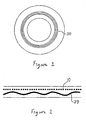
La
Le pneumatique comporte également une structure de renfort 10 ou de renforcement de type carcasse pourvue de renforts avantageusement configurés selon un agencement sensiblement radial. Cette structure peut être agencée de façon continue d'un bourrelet à l'autre, en passant par les flancs et le sommet du pneumatique, ou encore, elle peut comporter deux ou plusieurs parties, agencées par exemple le long des flancs, sans couvrir la totalité du sommet.The tire also comprises a reinforcing
Afin de positionner les fils de renforcement de façon aussi précise que possible, il est très avantageux de confectionner le pneumatique sur support rigide, par exemple un noyau rigide imposant la forme de sa cavité intérieure. On applique sur ce noyau, dans l'ordre requis par l'architecture finale, tous les constituants du pneumatique, qui sont disposés directement à leur place finale, sans que le profil du pneumatique doive être modifié lors de la confection.In order to position the reinforcing threads as accurately as possible, it is very advantageous to make the tire rigid support, for example a rigid core imposing the shape of its inner cavity. On this core, in the order required by the final architecture, are applied all the constituents of the tire, which are placed directly in their final place, without the profile of the tire having to be modified during manufacture.
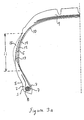
Deux principaux types d'ancrage de la structure de renfort de type carcasse sont possibles. De façon typique, le retournement de ladite structure 10 autour d'une tringle 7 au niveau du bourrelet 1 assure l'ancrage de la structure de renfort de type carcasse dans le bourrelet, tel qu'illustré par exemple à la
Autrement, la fonction d'ancrage peut être réalisée grâce à un agencement de fils circonférentiel, tel qu'illustré par exemple à la
Afin d'assurer un parfait ancrage de la structure de renfort, on réalise un bourrelet composite stratifié. A l'intérieur du bourrelet 1, entre les alignements de fil de la structure de renfort, on dispose les fils 21 orientés circonférentiellement. Ceux-ci sont disposés en une pile 22 comme sur les figures, ou en plusieurs piles adjacentes, ou en toute disposition judicieuse, selon le type de pneumatique et/ou les caractéristiques recherchées.In order to ensure perfect anchoring of the reinforcement structure, a laminated composite bead is produced. Inside the
Les portions d'extrémité radialement internes de la structure de renfort 10 coopèrent avec les enroulements filaires. Il se crée ainsi un ancrage de ces portions dans lesdits bourrelets. Afin de favoriser cet ancrage, l'espace entre les fils circonférentiels et la structure de renfort est occupé par un mélange caoutchoutique 60 de liaison ou d'ancrage. On peut également prévoir l'utilisation de plusieurs mélanges ayant des caractéristiques différentes, délimitant plusieurs zones, les combinaisons de mélanges et les agencements résultants étant quasi-illimités. A titre d'exemple non limitatif, le module d'élasticité d'un tel mélange peut atteindre ou dépasser 10 à 15 Mpa, et même dans certains cas atteindre, voire dépasser 40 Mpa.The radially inner end portions of the reinforcing
Les arrangements de fils peuvent être agencés et fabriqués de plusieurs façons. Par exemple, une pile peut avantageusement être constituée d'un seul fil enroulé (sensiblement à zéro degré) en spirale sur plusieurs tours, de préférence depuis le plus petit diamètre vers le plus grand diamètre. Une pile peut également être constituée de plusieurs fils concentriques posés l'un dans l'autre, de façon à ce que l'on superpose des anneaux de diamètre progressivement croissant. Il n'est pas nécessaire d'ajouter un mélange de caoutchouc pour assurer l'imprégnation du fil de renfort, ou des enroulements circonférentiels de fil.Wire arrangements can be arranged and manufactured in many ways. For example, a battery may advantageously consist of a single wire wound (substantially zero degrees) spirally over several turns, preferably from the smallest diameter to the largest diameter. A stack may also consist of several concentric threads placed one inside the other, so that one is superimposed rings of progressively increasing diameter. It is not necessary to add a rubber mixture to ensure the impregnation of the reinforcing thread, or circumferential windings of thread.
Les
Le ou lesdits fils circonférentiels sont de type à bi-module. Un premier module, (de 0,2 à 2 GPa), pour le fonctionnement normal, permettant d'obtenir des propriétés s'apparentant à de bons pneumatiques standard, avec des bonnes caractéristiques notamment de confort et de résistance au roulement. Un second module, (de 20 à 100 GPa), apparaissant lorsque les flancs sont affaissés et les fils circonférentiels assujettis à d'importantes contraintes d'élongation/d'étirement, permettant de rigidifier les flancs et de supporter la charge induite par la perte de pression. Les fils circonférentiels sont préférentiellement efficaces dans le second cas, et interfèrent peu ou pas avec les qualités du pneumatique utilisé à pression sensiblement normale.The one or more circumferential threads are of bi-module type. A first module, (from 0.2 to 2 GPa), for normal operation, to obtain properties similar to good standard tires, with good characteristics including comfort and rolling resistance. A second module, (20 to 100 GPa), appears when the flanks are collapsed and the circumferential yarns are subjected to significant elongation / stretching stresses, allowing stiffening of the flanks and supporting the load induced by the loss. pressure. The circumferential threads are preferably effective in the second case, and interfere little or not with the qualities of the tire used at substantially normal pressure.
Le pourcentage d'allongement préférentiel correspondant à un changement de caractéristique modulaire (changement de pente sur un graphique contrainte-allongement) se situe entre 1 et 4 %, et de préférence entre 2 et 3 %.The percentage of preferential elongation corresponding to a change of modular characteristic (change of slope on a stress-elongation graph) is between 1 and 4%, and preferably between 2 and 3%.
Selon un autre mode de réalisation illustré à la
La
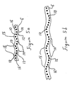
Les
Entre ces positions extrêmes, on peut retrouver une ou plusieurs séries de positions intermédiaires 16, comme illustré par exemple aux
Les
Les
En faisant un parallèle avec le comportement dynamique d'un pneumatique de type radial traditionnel (sans ondulations), on note les points suivants. Lors du passage au niveau de l'aire de contact 310, de multiples sollicitations mécaniques interviennent. Entre le point d'entrée et le point de sortie de l'aire de contact, le pneumatique subit une importante contrainte d'allongement dans le sens circonférentiel. Au niveau des flancs, ces sollicitations occasionnent un phénomène de « déradialisation » des fils de la structure de renfort. Les fils ont donc tendance à s'écarter les uns des autres, suite à un étirement élastique du mélange caoutchoutique du flanc entre les fils. Ce phénomène entraîne lui-même un certain échauffement du pneumatique, qui contribue à augmenter la résistance au roulement et affecte l'endurance du produit.By making a parallel with the dynamic behavior of a traditional radial-type tire (without corrugations), the following points are noted. When passing through the
Avec un pneumatique selon l'invention, comportant une zone de flanc avec ondulations, les mêmes sollicitations mécaniques se manifestent entre l'entrée et la sortie de l'aire de contact. Cependant, les ondulations procurent une sorte de « réserve » de matière, disponible pour répondre aux diverses sollicitations mécanique dues aux déformations au niveau du passage dans l'aire de contact, et en particulier les sollicitations circonférentielles. Cette réserve disponible réduit ou peut même dans certains cas éviter le recours à l'étirement du mélange caoutchoutique entre les fils. On assiste donc à une déformation des ondulations dans la zone angulaire du pneumatique correspondant à l'aire de contact. Lesdites ondulations « s'aplanissent », ou diminuent d'amplitude. Les sollicitations mécaniques dues à l'aire de contact sont donc en quelque sorte amorties ou absorbées par les ondulations des flancs. Cette déformation se réalise avec un échauffement sensiblement limité par rapport à un étirement du mélange caoutchoutique. Les caractéristiques de résistance au roulement et d'endurance sont par conséquent peu affectées.With a tire according to the invention, comprising a flank zone with corrugations, the same mechanical stresses occur between the entry and the exit of the contact area. However, the corrugations provide a kind of "reserve" of material, available to respond to the various mechanical stresses due to deformations at the passage in the contact area, and in particular the circumferential stresses. This reserve available reduces or may even in some cases avoid the use of stretching rubber mix between the son. There is thus a deformation of the corrugations in the angular zone of the tire corresponding to the area of contact. Said undulations "flatten out", or decrease in amplitude. The mechanical stresses due to the contact area are thus somehow damped or absorbed by the corrugations of the flanks. This deformation is achieved with a substantially limited heating compared to stretching the rubber mix. The rolling resistance and endurance characteristics are therefore not affected.
Lors de la phase d'aplanissement des ondulations, les fils 30 ont un comportement similaire, si bien que leurs ondulations s'aplanissent aussi, jusqu'à ce que les fils deviennent de plus en plus sujets à des efforts de tension circonférentiels. Les fils circonférentiels mis en tension engendrent un blocage sensiblement progressif du flambage des flancs. Finalement, ces fils ont un effet de soutien des flancs, qui ne peuvent plus s'affaisser. Les flancs peuvent donc soutenir ou supporter les efforts, un peu à la façon d'un pneumatique autoporteur, mais avec un soutien dû à un élément agissant circonférentiellement plutôt que radialement.During the flattening phase of the corrugations, the
Ce phénomène de blocage circonférentiel progressif permet ainsi d'avoir des situations distinctes : en mode de pression normale, avec les ondulations des fils circonférentiels et des fils de la structure de renfort de type carcasse, les flancs sont sensiblement souples ; en mode de pression faible, avec atténuation de plus en plus forte des deux types d'ondulations dans la portion du pneumatique correspondant sensiblement à la zone de contact avec le sol, la rigidification des flancs permet de réaliser une fonction d'auto-portage.This progressive circumferential locking phenomenon thus makes it possible to have distinct situations: in normal pressure mode, with the corrugations of the circumferential threads and the threads of the carcass-type reinforcement structure, the flanks are substantially flexible; in low pressure mode, with increasing attenuation of the two types of corrugations in the portion of the tire corresponding substantially to the area of contact with the ground, the stiffening of the sidewalls allows for a self-porting function.
Dans le cas où le moyen de support de flanc est un câble bi-module, l'effet est comparable, sauf que l'élasticité est conférée par les câbles circonférentiels plutôt que par les ondulations.In the case where the flank support means is a bi-module cable, the effect is comparable, except that the elasticity is conferred by the circumferential cables rather than by the corrugations.
La fabrication industrielle d'un pneumatique selon l'invention peut être réalisée selon plusieurs types de procédés. De manière avantageuse, on utilise un principe de pose sur noyau central permettant soit la pose individuelle des éléments constituants tels les mélanges caoutchoutiques et les renforts (fils) ou encore la pose de produits semi-finis tels des lamelles caoutchoutiques renforcées. Avec un tel procédé, on utilise un noyau central pourvu d'ondulations dans la zone correspondant sensiblement à la zone 11 du pneumatique, permettant ainsi de conférer, dès la pose des différents éléments, la forme ou profil ondulé des flancs, telle que préalablement décrite.The industrial manufacture of a tire according to the invention can be carried out according to several types of processes. Advantageously, a principle of laying on a central core is used allowing either the individual laying of the constituent elements such as rubber mixes and reinforcements (son) or the laying of semi-finished products such as rubber reinforced lamellae. With such a method, a central core is used provided with corrugations in the zone corresponding substantially to the zone 11 of the tire, thus making it possible to confer, as soon as the various elements are laid, the corrugated shape or profile of the flanks, as previously described. .
Claims (3)
- A tyre comprising at least one carcass-type reinforcement structure anchored on each side of the tyre in a bead whose base is intended to be fitted on a rim seat, each bead being extended radially towards the outside by a sidewall, the sidewalls meeting up radially towards the outside with a tread and comprising at least one sidewall support means exhibiting a substantially progressive increase in rigidity, disposed in the substantially median portion of said sidewalls, the carcass-type reinforcement structure extending circumferentially from the bead towards said sidewall, a crown reinforcement, each of the beads comprising furthermore an anchoring zone allowing the reinforcement structure to be retained in each of said beads, characterised in that said support means comprising at least one circumferential cord arranged on the circumference in different axial positions, so as to form around the circumference a succession of substantially regular undulations forming an undulating circumferential profile.
- A tyre according to Claim 1, in which said carcass-type reinforcement structure is arranged in such a way that, in the substantially median portion of the sidewall, the cords of said reinforcement structure exhibit different axial positions on the circumference, so as to form around the circumference a succession of substantially regular undulations forming an undulating circumferential profile.
- A tyre according to Claim 2, in which the undulations formed by said circumferential cords on the one hand and the undulations formed by the reinforcement structure cords on the other hand are substantially congruent.
Applications Claiming Priority (3)
| Application Number | Priority Date | Filing Date | Title |
|---|---|---|---|
| FR0216749 | 2002-12-26 | ||
| FR0216749 | 2002-12-26 | ||
| PCT/EP2003/012925 WO2004058516A1 (en) | 2002-12-26 | 2003-11-19 | Run-flat tyre with variable-rigidity sidewalls |
Publications (2)
| Publication Number | Publication Date |
|---|---|
| EP1578620A1 EP1578620A1 (en) | 2005-09-28 |
| EP1578620B1 true EP1578620B1 (en) | 2008-09-17 |
Family
ID=32669142
Family Applications (1)
| Application Number | Title | Priority Date | Filing Date |
|---|---|---|---|
| EP03779985A Expired - Lifetime EP1578620B1 (en) | 2002-12-26 | 2003-11-19 | Run-flat tyre with variable-rigidity sidewalls |
Country Status (9)
| Country | Link |
|---|---|
| US (1) | US7281558B2 (en) |
| EP (1) | EP1578620B1 (en) |
| JP (1) | JP4522865B2 (en) |
| KR (1) | KR20050084491A (en) |
| CN (1) | CN1729110B (en) |
| AT (1) | ATE408526T1 (en) |
| AU (1) | AU2003288113A1 (en) |
| DE (1) | DE60323675D1 (en) |
| WO (1) | WO2004058516A1 (en) |
Families Citing this family (8)
| Publication number | Priority date | Publication date | Assignee | Title |
|---|---|---|---|---|
| ATE387323T1 (en) * | 2002-11-18 | 2008-03-15 | Michelin Soc Tech | TIRE WITH CURVED SIDEWALLS FOR GREATER MOBILITY |
| FR2886580B1 (en) * | 2005-06-02 | 2008-01-04 | Michelin Soc Tech | PNEUMATIC WITH FLANK ONDULES |
| WO2011092709A1 (en) | 2010-02-01 | 2011-08-04 | Galileo Wheel Ltd. | Deformable wheel assembly |
| TR201802974T4 (en) | 2011-07-27 | 2018-03-21 | Galileo Wheel Ltd | Tire for the surface tool. |
| JP5261584B2 (en) * | 2012-01-20 | 2013-08-14 | 住友ゴム工業株式会社 | Pneumatic tire manufacturing method |
| CA2915483C (en) | 2013-06-15 | 2021-11-16 | Ronald Thompson | Annular ring and non-pneumatic tire |
| US10953696B2 (en) | 2015-02-04 | 2021-03-23 | Camso Inc | Non-pneumatic tire and other annular devices |
| US10442252B2 (en) * | 2015-04-09 | 2019-10-15 | Jeffrey P Douglas | Tire with high strength corrugated sidewalls |
Family Cites Families (24)
| Publication number | Priority date | Publication date | Assignee | Title |
|---|---|---|---|---|
| US3240250A (en) * | 1964-06-11 | 1966-03-15 | Nat Standard Co | Pneumatic tires |
| NL130258C (en) * | 1965-07-28 | |||
| BE794658A (en) * | 1972-02-03 | 1973-07-30 | Michelin & Cie | IMPROVEMENTS TO TIRE PACKAGES |
| JPS52106504A (en) | 1976-03-04 | 1977-09-07 | Bridgestone Corp | Radial pneumatic tire for rough ground having superior side cut resist ability |
| US4436139A (en) * | 1981-07-20 | 1984-03-13 | Motor Wheel Corporation | Method and apparatus for manufacture of brake drums |
| JPH02234812A (en) * | 1989-03-08 | 1990-09-18 | Bridgestone Corp | Pneumatic tire |
| US5660656A (en) * | 1992-08-05 | 1997-08-26 | Sedepro | Tire with anchored carcass |
| JPH06340209A (en) * | 1993-06-01 | 1994-12-13 | Bridgestone Corp | Pneumatic radial tire for construction vehicle |
| JP2643085B2 (en) * | 1994-02-09 | 1997-08-20 | 住友ゴム工業株式会社 | Pneumatic tire and manufacturing method thereof |
| JPH09193625A (en) * | 1996-01-17 | 1997-07-29 | Bridgestone Corp | Pneumatic tire |
| JP3665884B2 (en) * | 1996-08-05 | 2005-06-29 | 東洋ゴム工業株式会社 | Pneumatic radial tire |
| JP3418519B2 (en) * | 1997-02-20 | 2003-06-23 | 不二精工株式会社 | Pneumatic radial tire |
| US6279630B1 (en) * | 1998-12-23 | 2001-08-28 | Daimlerchrysler Ag | Non pneumatic tires |
| US6695025B1 (en) * | 1999-05-18 | 2004-02-24 | The Goodyear Tire & Rubber Company | Runflat tire construction with ply cords having a variable modulus of elasticity |
| EP1100688A1 (en) * | 1999-05-27 | 2001-05-23 | Michelin Recherche Et Technique S.A. | Runflat tire having optimized carcass path |
| JP3449692B2 (en) * | 1999-09-24 | 2003-09-22 | 不二精工株式会社 | Pneumatic radial tire |
| US6453961B1 (en) * | 2000-06-01 | 2002-09-24 | The Goodyear Tire & Rubber Company | Variable-stiffness wedge insert for runflat tire |
| BR0112888B1 (en) * | 2000-07-31 | 2009-12-01 | two-wheel tire and use of a substantially peripheral anti-vibration means. | |
| JP4537561B2 (en) * | 2000-09-28 | 2010-09-01 | 住友ゴム工業株式会社 | Pneumatic tire |
| WO2002030691A1 (en) * | 2000-10-10 | 2002-04-18 | Societe De Technologie Michelin | Tire having more carcass layers in sidewall than in bead |
| AU2002212316A1 (en) * | 2000-10-10 | 2002-04-22 | Michelin Recherche Et Technique S.A. | Tire having an outer carcass path |
| ES2259012T3 (en) * | 2001-11-22 | 2006-09-16 | Pirelli Tyre S.P.A. | TIRE FOR VEHICLE WITH REINFORCED SIDE. |
| JP2003231406A (en) * | 2002-02-12 | 2003-08-19 | Yokohama Rubber Co Ltd:The | Pneumatic tire |
| ATE387323T1 (en) * | 2002-11-18 | 2008-03-15 | Michelin Soc Tech | TIRE WITH CURVED SIDEWALLS FOR GREATER MOBILITY |
-
2003
- 2003-11-19 EP EP03779985A patent/EP1578620B1/en not_active Expired - Lifetime
- 2003-11-19 JP JP2004562551A patent/JP4522865B2/en not_active Expired - Fee Related
- 2003-11-19 AT AT03779985T patent/ATE408526T1/en not_active IP Right Cessation
- 2003-11-19 CN CN2003801072774A patent/CN1729110B/en not_active Expired - Fee Related
- 2003-11-19 WO PCT/EP2003/012925 patent/WO2004058516A1/en active IP Right Grant
- 2003-11-19 DE DE60323675T patent/DE60323675D1/en not_active Expired - Lifetime
- 2003-11-19 AU AU2003288113A patent/AU2003288113A1/en not_active Abandoned
- 2003-11-19 KR KR1020057011951A patent/KR20050084491A/en not_active Application Discontinuation
-
2005
- 2005-06-24 US US11/165,351 patent/US7281558B2/en not_active Expired - Fee Related
Also Published As
| Publication number | Publication date |
|---|---|
| WO2004058516A1 (en) | 2004-07-15 |
| JP4522865B2 (en) | 2010-08-11 |
| US20050236086A1 (en) | 2005-10-27 |
| KR20050084491A (en) | 2005-08-26 |
| DE60323675D1 (en) | 2008-10-30 |
| CN1729110B (en) | 2010-10-13 |
| AU2003288113A1 (en) | 2004-07-22 |
| JP2006512243A (en) | 2006-04-13 |
| CN1729110A (en) | 2006-02-01 |
| EP1578620A1 (en) | 2005-09-28 |
| US7281558B2 (en) | 2007-10-16 |
| ATE408526T1 (en) | 2008-10-15 |
Similar Documents
| Publication | Publication Date | Title |
|---|---|---|
| EP3568289B1 (en) | Assembly comprising an elastic structure and a supporting structure | |
| EP3568290B1 (en) | Assembly comprising a partially breakable fabric and a supporting structure | |
| EP3390114B1 (en) | Assembly for tyre including impregnated woven or knitted fabric(s) and a sacrificial holding means | |
| EP3568291B1 (en) | Tyre assembly comprising a breakable structure and a bearing structure, tyre and method of manufacturing said tyre | |
| EP1237739B1 (en) | Tyre bead with extended mobility | |
| EP1565328B1 (en) | Tyre with extended mobility comprising corrugated sidewalls | |
| EP1254034B1 (en) | Tyre bead with extended mobility | |
| EP1578620B1 (en) | Run-flat tyre with variable-rigidity sidewalls | |
| EP1395448B1 (en) | Tyre with double-anchoring casing ply | |
| EP1461215B1 (en) | Double half-carcass tyre with an adapted crown area | |
| EP2331350B1 (en) | Tyre for heavy vehicles comprising, at least in each shoulder, at least two additional layers in the crown reinforcement | |
| EP1789266B1 (en) | Extended mobility tyre comprising several superlow anchor areas | |
| WO2006024561A1 (en) | Extended mobility tyre comprising an anchoring area having a high moment of inertia | |
| EP1554133B1 (en) | Extended mobility tyre comprising bead with symmetrical force distribution | |
| WO2002000451A1 (en) | Double half-carcass tyre | |
| EP1893421B1 (en) | Tyre with corrugated sidewalls | |
| EP1534542A1 (en) | Tyre with non-linear anchoring of reinforcing structure | |
| EP1101633B1 (en) | Tire with decoupled low zone | |
| EP1663672B1 (en) | Tyre with extended mobility with asymmetrically arranged beads | |
| WO2003093034A2 (en) | Tyre with bead provided with a wire structure divided into two zones | |
| WO2002000455A1 (en) | Tyre lateral reinforcing element | |
| WO2003093032A1 (en) | Tyre with bead comprising a micro-deformable anchor zone | |
| WO2003093033A1 (en) | Tyre with bead provided with a zone facilitating mounting/dismounting |
Legal Events
| Date | Code | Title | Description |
|---|---|---|---|
| PUAI | Public reference made under article 153(3) epc to a published international application that has entered the european phase |
Free format text: ORIGINAL CODE: 0009012 |
|
| 17P | Request for examination filed |
Effective date: 20050726 |
|
| AK | Designated contracting states |
Kind code of ref document: A1 Designated state(s): AT BE BG CH CY CZ DE DK EE ES FI FR GB GR HU IE IT LI LU MC NL PT RO SE SI SK TR |
|
| AX | Request for extension of the european patent |
Extension state: AL LT LV MK |
|
| DAX | Request for extension of the european patent (deleted) | ||
| 17Q | First examination report despatched |
Effective date: 20071129 |
|
| GRAP | Despatch of communication of intention to grant a patent |
Free format text: ORIGINAL CODE: EPIDOSNIGR1 |
|
| GRAS | Grant fee paid |
Free format text: ORIGINAL CODE: EPIDOSNIGR3 |
|
| GRAA | (expected) grant |
Free format text: ORIGINAL CODE: 0009210 |
|
| AK | Designated contracting states |
Kind code of ref document: B1 Designated state(s): AT BE BG CH CY CZ DE DK EE ES FI FR GB GR HU IE IT LI LU MC NL PT RO SE SI SK TR |
|
| REG | Reference to a national code |
Ref country code: GB Ref legal event code: FG4D Free format text: NOT ENGLISH |
|
| REG | Reference to a national code |
Ref country code: CH Ref legal event code: EP |
|
| REG | Reference to a national code |
Ref country code: IE Ref legal event code: FG4D Free format text: LANGUAGE OF EP DOCUMENT: FRENCH |
|
| REF | Corresponds to: |
Ref document number: 60323675 Country of ref document: DE Date of ref document: 20081030 Kind code of ref document: P |
|
| PG25 | Lapsed in a contracting state [announced via postgrant information from national office to epo] |
Ref country code: AT Free format text: LAPSE BECAUSE OF FAILURE TO SUBMIT A TRANSLATION OF THE DESCRIPTION OR TO PAY THE FEE WITHIN THE PRESCRIBED TIME-LIMIT Effective date: 20080917 Ref country code: FI Free format text: LAPSE BECAUSE OF FAILURE TO SUBMIT A TRANSLATION OF THE DESCRIPTION OR TO PAY THE FEE WITHIN THE PRESCRIBED TIME-LIMIT Effective date: 20080917 Ref country code: SI Free format text: LAPSE BECAUSE OF FAILURE TO SUBMIT A TRANSLATION OF THE DESCRIPTION OR TO PAY THE FEE WITHIN THE PRESCRIBED TIME-LIMIT Effective date: 20080917 |
|
| NLV1 | Nl: lapsed or annulled due to failure to fulfill the requirements of art. 29p and 29m of the patents act | ||
| REG | Reference to a national code |
Ref country code: IE Ref legal event code: FD4D |
|
| PG25 | Lapsed in a contracting state [announced via postgrant information from national office to epo] |
Ref country code: ES Free format text: LAPSE BECAUSE OF FAILURE TO SUBMIT A TRANSLATION OF THE DESCRIPTION OR TO PAY THE FEE WITHIN THE PRESCRIBED TIME-LIMIT Effective date: 20081228 Ref country code: BG Free format text: LAPSE BECAUSE OF FAILURE TO SUBMIT A TRANSLATION OF THE DESCRIPTION OR TO PAY THE FEE WITHIN THE PRESCRIBED TIME-LIMIT Effective date: 20081217 |
|
| PG25 | Lapsed in a contracting state [announced via postgrant information from national office to epo] |
Ref country code: SK Free format text: LAPSE BECAUSE OF FAILURE TO SUBMIT A TRANSLATION OF THE DESCRIPTION OR TO PAY THE FEE WITHIN THE PRESCRIBED TIME-LIMIT Effective date: 20080917 Ref country code: RO Free format text: LAPSE BECAUSE OF FAILURE TO SUBMIT A TRANSLATION OF THE DESCRIPTION OR TO PAY THE FEE WITHIN THE PRESCRIBED TIME-LIMIT Effective date: 20080917 Ref country code: PT Free format text: LAPSE BECAUSE OF FAILURE TO SUBMIT A TRANSLATION OF THE DESCRIPTION OR TO PAY THE FEE WITHIN THE PRESCRIBED TIME-LIMIT Effective date: 20090217 Ref country code: NL Free format text: LAPSE BECAUSE OF FAILURE TO SUBMIT A TRANSLATION OF THE DESCRIPTION OR TO PAY THE FEE WITHIN THE PRESCRIBED TIME-LIMIT Effective date: 20080917 Ref country code: CZ Free format text: LAPSE BECAUSE OF FAILURE TO SUBMIT A TRANSLATION OF THE DESCRIPTION OR TO PAY THE FEE WITHIN THE PRESCRIBED TIME-LIMIT Effective date: 20080917 |
|
| BERE | Be: lapsed |
Owner name: MICHELIN RECHERCHE ET TECHNIQUE S.A. Effective date: 20081130 Owner name: SOC. DE TECHNOLOGIE MICHELIN Effective date: 20081130 |
|
| PG25 | Lapsed in a contracting state [announced via postgrant information from national office to epo] |
Ref country code: MC Free format text: LAPSE BECAUSE OF NON-PAYMENT OF DUE FEES Effective date: 20081130 |
|
| REG | Reference to a national code |
Ref country code: CH Ref legal event code: PL |
|
| PLBE | No opposition filed within time limit |
Free format text: ORIGINAL CODE: 0009261 |
|
| STAA | Information on the status of an ep patent application or granted ep patent |
Free format text: STATUS: NO OPPOSITION FILED WITHIN TIME LIMIT |
|
| PG25 | Lapsed in a contracting state [announced via postgrant information from national office to epo] |
Ref country code: DK Free format text: LAPSE BECAUSE OF FAILURE TO SUBMIT A TRANSLATION OF THE DESCRIPTION OR TO PAY THE FEE WITHIN THE PRESCRIBED TIME-LIMIT Effective date: 20080917 Ref country code: IE Free format text: LAPSE BECAUSE OF FAILURE TO SUBMIT A TRANSLATION OF THE DESCRIPTION OR TO PAY THE FEE WITHIN THE PRESCRIBED TIME-LIMIT Effective date: 20080917 Ref country code: EE Free format text: LAPSE BECAUSE OF FAILURE TO SUBMIT A TRANSLATION OF THE DESCRIPTION OR TO PAY THE FEE WITHIN THE PRESCRIBED TIME-LIMIT Effective date: 20080917 |
|
| 26N | No opposition filed |
Effective date: 20090618 |
|
| GBPC | Gb: european patent ceased through non-payment of renewal fee |
Effective date: 20081217 |
|
| PG25 | Lapsed in a contracting state [announced via postgrant information from national office to epo] |
Ref country code: BE Free format text: LAPSE BECAUSE OF NON-PAYMENT OF DUE FEES Effective date: 20081130 |
|
| PG25 | Lapsed in a contracting state [announced via postgrant information from national office to epo] |
Ref country code: CH Free format text: LAPSE BECAUSE OF NON-PAYMENT OF DUE FEES Effective date: 20081130 Ref country code: LI Free format text: LAPSE BECAUSE OF NON-PAYMENT OF DUE FEES Effective date: 20081130 |
|
| PG25 | Lapsed in a contracting state [announced via postgrant information from national office to epo] |
Ref country code: GB Free format text: LAPSE BECAUSE OF NON-PAYMENT OF DUE FEES Effective date: 20081217 |
|
| PG25 | Lapsed in a contracting state [announced via postgrant information from national office to epo] |
Ref country code: SE Free format text: LAPSE BECAUSE OF FAILURE TO SUBMIT A TRANSLATION OF THE DESCRIPTION OR TO PAY THE FEE WITHIN THE PRESCRIBED TIME-LIMIT Effective date: 20081217 |
|
| PG25 | Lapsed in a contracting state [announced via postgrant information from national office to epo] |
Ref country code: HU Free format text: LAPSE BECAUSE OF FAILURE TO SUBMIT A TRANSLATION OF THE DESCRIPTION OR TO PAY THE FEE WITHIN THE PRESCRIBED TIME-LIMIT Effective date: 20090318 Ref country code: CY Free format text: LAPSE BECAUSE OF FAILURE TO SUBMIT A TRANSLATION OF THE DESCRIPTION OR TO PAY THE FEE WITHIN THE PRESCRIBED TIME-LIMIT Effective date: 20080917 Ref country code: LU Free format text: LAPSE BECAUSE OF NON-PAYMENT OF DUE FEES Effective date: 20081119 |
|
| PG25 | Lapsed in a contracting state [announced via postgrant information from national office to epo] |
Ref country code: TR Free format text: LAPSE BECAUSE OF FAILURE TO SUBMIT A TRANSLATION OF THE DESCRIPTION OR TO PAY THE FEE WITHIN THE PRESCRIBED TIME-LIMIT Effective date: 20080917 |
|
| PG25 | Lapsed in a contracting state [announced via postgrant information from national office to epo] |
Ref country code: GR Free format text: LAPSE BECAUSE OF FAILURE TO SUBMIT A TRANSLATION OF THE DESCRIPTION OR TO PAY THE FEE WITHIN THE PRESCRIBED TIME-LIMIT Effective date: 20081218 |
|
| PGFP | Annual fee paid to national office [announced via postgrant information from national office to epo] |
Ref country code: FR Payment date: 20121130 Year of fee payment: 10 Ref country code: DE Payment date: 20121121 Year of fee payment: 10 |
|
| PGFP | Annual fee paid to national office [announced via postgrant information from national office to epo] |
Ref country code: IT Payment date: 20121127 Year of fee payment: 10 |
|
| REG | Reference to a national code |
Ref country code: DE Ref legal event code: R119 Ref document number: 60323675 Country of ref document: DE |
|
| REG | Reference to a national code |
Ref country code: FR Ref legal event code: ST Effective date: 20140731 |
|
| PG25 | Lapsed in a contracting state [announced via postgrant information from national office to epo] |
Ref country code: DE Free format text: LAPSE BECAUSE OF NON-PAYMENT OF DUE FEES Effective date: 20140603 Ref country code: IT Free format text: LAPSE BECAUSE OF NON-PAYMENT OF DUE FEES Effective date: 20131119 |
|
| REG | Reference to a national code |
Ref country code: DE Ref legal event code: R119 Ref document number: 60323675 Country of ref document: DE Effective date: 20140603 |
|
| PG25 | Lapsed in a contracting state [announced via postgrant information from national office to epo] |
Ref country code: FR Free format text: LAPSE BECAUSE OF NON-PAYMENT OF DUE FEES Effective date: 20131202 |