EP1578185A1 - Vorrichtung zur Erzeugung einer elektro-magnetisch abgeschirmten Verbindung - Google Patents
Vorrichtung zur Erzeugung einer elektro-magnetisch abgeschirmten Verbindung Download PDFInfo
- Publication number
- EP1578185A1 EP1578185A1 EP05002635A EP05002635A EP1578185A1 EP 1578185 A1 EP1578185 A1 EP 1578185A1 EP 05002635 A EP05002635 A EP 05002635A EP 05002635 A EP05002635 A EP 05002635A EP 1578185 A1 EP1578185 A1 EP 1578185A1
- Authority
- EP
- European Patent Office
- Prior art keywords
- plug
- unit
- carrier element
- partial
- partial shield
- Prior art date
- Legal status (The legal status is an assumption and is not a legal conclusion. Google has not performed a legal analysis and makes no representation as to the accuracy of the status listed.)
- Granted
Links
- 238000007667 floating Methods 0.000 claims description 27
- 230000005540 biological transmission Effects 0.000 claims description 6
- 239000011324 bead Substances 0.000 claims description 2
- 230000002093 peripheral effect Effects 0.000 claims description 2
- 229910052751 metal Inorganic materials 0.000 description 6
- 239000000725 suspension Substances 0.000 description 6
- 239000002184 metal Substances 0.000 description 5
- 238000005516 engineering process Methods 0.000 description 3
- DMFGNRRURHSENX-UHFFFAOYSA-N beryllium copper Chemical compound [Be].[Cu] DMFGNRRURHSENX-UHFFFAOYSA-N 0.000 description 2
- 238000013500 data storage Methods 0.000 description 2
- 238000013461 design Methods 0.000 description 2
- 230000006870 function Effects 0.000 description 2
- 230000001771 impaired effect Effects 0.000 description 2
- 238000005452 bending Methods 0.000 description 1
- 238000010276 construction Methods 0.000 description 1
- 238000011161 development Methods 0.000 description 1
- 230000018109 developmental process Effects 0.000 description 1
- 238000010586 diagram Methods 0.000 description 1
- 239000006185 dispersion Substances 0.000 description 1
- 238000003780 insertion Methods 0.000 description 1
- 230000037431 insertion Effects 0.000 description 1
- 230000007257 malfunction Effects 0.000 description 1
- 238000004519 manufacturing process Methods 0.000 description 1
- 238000013507 mapping Methods 0.000 description 1
- 238000012805 post-processing Methods 0.000 description 1
- 238000012216 screening Methods 0.000 description 1
- 238000000926 separation method Methods 0.000 description 1
- 238000012549 training Methods 0.000 description 1
Images


Classifications
-
- H—ELECTRICITY
- H01—ELECTRIC ELEMENTS
- H01R—ELECTRICALLY-CONDUCTIVE CONNECTIONS; STRUCTURAL ASSOCIATIONS OF A PLURALITY OF MUTUALLY-INSULATED ELECTRICAL CONNECTING ELEMENTS; COUPLING DEVICES; CURRENT COLLECTORS
- H01R13/00—Details of coupling devices of the kinds covered by groups H01R12/70 or H01R24/00 - H01R33/00
- H01R13/648—Protective earth or shield arrangements on coupling devices, e.g. anti-static shielding
- H01R13/658—High frequency shielding arrangements, e.g. against EMI [Electro-Magnetic Interference] or EMP [Electro-Magnetic Pulse]
- H01R13/6591—Specific features or arrangements of connection of shield to conductive members
- H01R13/6597—Specific features or arrangements of connection of shield to conductive members the conductive member being a contact of the connector
-
- H—ELECTRICITY
- H01—ELECTRIC ELEMENTS
- H01R—ELECTRICALLY-CONDUCTIVE CONNECTIONS; STRUCTURAL ASSOCIATIONS OF A PLURALITY OF MUTUALLY-INSULATED ELECTRICAL CONNECTING ELEMENTS; COUPLING DEVICES; CURRENT COLLECTORS
- H01R13/00—Details of coupling devices of the kinds covered by groups H01R12/70 or H01R24/00 - H01R33/00
- H01R13/62—Means for facilitating engagement or disengagement of coupling parts or for holding them in engagement
- H01R13/629—Additional means for facilitating engagement or disengagement of coupling parts, e.g. aligning or guiding means, levers, gas pressure electrical locking indicators, manufacturing tolerances
- H01R13/631—Additional means for facilitating engagement or disengagement of coupling parts, e.g. aligning or guiding means, levers, gas pressure electrical locking indicators, manufacturing tolerances for engagement only
- H01R13/6315—Additional means for facilitating engagement or disengagement of coupling parts, e.g. aligning or guiding means, levers, gas pressure electrical locking indicators, manufacturing tolerances for engagement only allowing relative movement between coupling parts, e.g. floating connection
-
- H—ELECTRICITY
- H01—ELECTRIC ELEMENTS
- H01R—ELECTRICALLY-CONDUCTIVE CONNECTIONS; STRUCTURAL ASSOCIATIONS OF A PLURALITY OF MUTUALLY-INSULATED ELECTRICAL CONNECTING ELEMENTS; COUPLING DEVICES; CURRENT COLLECTORS
- H01R13/00—Details of coupling devices of the kinds covered by groups H01R12/70 or H01R24/00 - H01R33/00
- H01R13/648—Protective earth or shield arrangements on coupling devices, e.g. anti-static shielding
- H01R13/658—High frequency shielding arrangements, e.g. against EMI [Electro-Magnetic Interference] or EMP [Electro-Magnetic Pulse]
- H01R13/6581—Shield structure
-
- H—ELECTRICITY
- H01—ELECTRIC ELEMENTS
- H01R—ELECTRICALLY-CONDUCTIVE CONNECTIONS; STRUCTURAL ASSOCIATIONS OF A PLURALITY OF MUTUALLY-INSULATED ELECTRICAL CONNECTING ELEMENTS; COUPLING DEVICES; CURRENT COLLECTORS
- H01R13/00—Details of coupling devices of the kinds covered by groups H01R12/70 or H01R24/00 - H01R33/00
- H01R13/73—Means for mounting coupling parts to apparatus or structures, e.g. to a wall
- H01R13/74—Means for mounting coupling parts in openings of a panel
Definitions
- the invention relates to a device for generating an electro-magnetically shielded connection between a connector assembly having at least one plug a first unit and one at least a corresponding socket having bushing arrangement a second unit, wherein the at least a plug and the at least one socket in their interconnected state a plug connection form.
- a reliable electro-magnetically shielded To create a plug connection becomes all the more complicated the more plug connections or plug / socket pairs between the units to be joined are, especially if this is a floating Suspension is necessary.
- a high-frequency data transmission is, for example in so-called hard disk storage or flight data storage used on which during a picture flight an airplane flying from a digital camera accumulating data are stored. With this data it can be e.g. to image data, supplementary data too the images, such as Mission data, system information or general information for postprocessing act.
- the flight data store is in general designed as mass storage for "digital mapping camera".
- Every flight data memory a stand-alone unit that has an image data port connected to the digital camera.
- each storage unit is mechanically fastened and in another operation electrically connected with all necessary cables. After the landing the flight data memory is removed and the Image data copied to a terrestrial mass storage.
- a disadvantage of the known flight data storage that the connection of the flight data memory with the continuing cable tedious and because of the cramped Space in the aircraft often very difficult is. This is especially true at high data rates. A wrong connection of cables can lead to a malfunction. Especially significant is also that the connector reliable, in particular vibration and shockproof, since otherwise due to the flight movements of the aircraft the risk of accidental disconnection is to be feared.
- the present invention is based on the object an electro-magnetically shielded connection between at least one plug and one socket especially if these each with a electronic unit are connected, the device in a structurally simple way a permanent and reliable electro-magnetic shielding should also ensure a regular release.
- the shielding device is the function “electromagnetic shielding" and the Function "electrical connection” separated from each other.
- the solution according to the invention makes it possible to use a entire plug or socket arrangement, independent on the number of plugs and sockets, electro-magnetic by one of the plugs or sockets independent Shield shielding.
- the Plug or the sockets can thus be flexible or be suspended floating without this the electromagnetic shielding is impaired.
- the solution according to the invention can be easily and produce economically. Due to the separation of Electromagnetic shielding from the actual Plug connection becomes the electromagnetic shielding by contacting the plugs with the sockets not worn or impaired. This results a permanently reliable shielding of the connection.
- Another advantage of the solution according to the invention consists in that the shielding in easier Way, for example via a screw, but also via any other connection technology, can be connected to the housing of the unit, which includes the plugs or sockets. These Connection is independent of a floating one or flexible suspension of the plug or sockets. This ensures that the case of the Units connected via the connector be, the same electrical potential exhibit. Potential differences between the housings and thus disturbance dispersions are thus reliable avoided.
- the plugs and sockets in a special cost-effective Only form plastic.
- One cost-intensive metallically shielded housing for every plug and socket is no longer necessary.
- the two partial shields contact each other electromagnetically, if the at least one plug the at least one Bush contacted.
- the first partial shielding with the first Unit and the second partial shield with the second Unit is electromagnetically tightly connected. This For example, by a screw or a other connection technology done.
- the plug connection between the Plug and the socket is closed, arises in addition to the shield an electrical connection between the first and the second unit, thereby whose electrical potentials are adjusted.
- the at least one Plug is connected to a first carrier element, which is provided with the first partial shielding, and at least one socket with a second support member connected, which with the second Partial shield is provided.
- the support members allow one of the units independent arrangement.
- the first Carrier element with the first partial shield floating attached to the housing of the intended unit become.
- the second carrier element may be attached to the Housing of the other unit also floating or be fixed immovably.
- the support elements on the respective unit can in easy way an electro-magnetic tight connection be created to this housing.
- the Partial shields provided with the carrier elements are created in the manner already described one Electro-magnetic tight shielding for the connectors as well as an electrical connection between the housings of the two units.
- the at least one plug with the first carrier element and the at least one Socket releasably connected to the second carrier element is. It is also advantageous if the at least a plug and / or the at least one socket floating or flexible with the respective support element connected is.
- a floating or flexible arrangement at least one plug or a corresponding one Socket has been found to be advantageous for possible tolerances when closing the Balance plug connection. Because the electro-magnetic Shielding or the balance between the potentials of the housing of the two units independently from a floating arrangement of plugs or the sockets, the described ones occur Disadvantages of the prior art in this case not on.
- the floating arranged carrier element for example formed substantially plate-shaped be and have a protruding edge through known from the general state of the art spring elements floating or flexible with the associated Unit is connected.
- the floating suspension of at least one of the two Carrier elements makes it possible that the partial shields the support elements which the electro-magnetic Shielding form accordingly can align each other. I'm trying exposed that the floating suspension of a the two support elements is sufficient for this purpose.
- the other carrier element can also be plate-shaped trained but immovable with the associated Unit to be connected.
- the partial shields of the two support elements can For example, each formed as a metal shell be, which the respectively associated plug or Socket assembly surrounds or circumferentially arranged around this is.
- a possible training of partial shielding can also be that these essentially formed linearly extending projections which is essentially in the form of a rectangle are arranged with each other and the plug or the Surrounded socket arrangement.
- Another alternative Embodiment of the partial shield for example consist in that the support element plate-shaped is formed, with a protruding plate edge is provided, which the plug or the socket assembly surrounds and formed as a partial shield is.
- the partial shields as projections or as a plate edge, it has to be advantageous exposed when having these contact springs or are designed as contact springs.
- the contact springs can, for example, as a curved Be formed sheet metal elements. An education out Beryllium copper has proved to be particularly suitable exposed.
- the embodiment shows a device for generating an electro-magnetically shielded connection between a connector 1 having at least one Connector assembly 2 of a first unit 3 and an at least one corresponding socket 4 having Bushing arrangement 5 of a second unit 6.
- the first unit 3 and the second unit 6 can be designed as any technical devices, which via formed by plug 1 and 4 sockets Contact connectors 7.
- the second unit 6 may e.g. as a laptop and the first Unit 3 designed as a charging or connecting station be.
- the first unit 3 can also be considered more general Equipment cabinet or as a system unit, for example be trained in medical technology, in the a correspondingly portable second unit 6, e.g. one System element, a medical device or the like, is used.
- the embodiment of the first Unit 3 or the second unit 6 are not Set limits.
- the device according to the invention can be used for any technical devices that to be connected electronically.
- the second unit is designed as a flight data memory 6, on the during a picture flight of an airplane 8 from a digital camera (not shown in detail) accumulating data can be stored.
- the second unit 3 is here as one for receiving the flight data memory 6 suitable adapter 3 is formed, wherein the Adpater 3 electrically and mechanically connected to the aircraft 8 is.
- the flight data memory 6 can, for example, several Storage media (not shown) and optionally include further system components. digital Cameras for recording such data are from the well known in the art, why in the embodiment of this is not closer will be received.
- the flight data memory is 6 by means of a locking device 9 with the adapter 3 connected or braced.
- a handle 10 For easy Handling or insertion of the flight data memory 6 is this provided on its upper side with a handle 10.
- the flight data memory 6 several storage media are arranged, these are thus by the Handle 10 and the housing 6a of the flight data memory. 6 combined to a removable unit.
- the flight data memory is 6 formed as an independent unit that has a Image data connection with a not shown digital camera is connected. Furthermore, a control data input, a control data output and a Supply voltage input and an image data interface available.
- FIG 3 the said connections or inputs and Outputs in the form of the socket assembly 5 shown.
- the sockets 4 are for contacting the plug 1 provided in accordance with Figure 2 and 4, whereby a corresponding Number of connectors 7 closed becomes.
- the plug arrangement 2 of the adapter 3 on two connectors 1.
- the bushing arrangement 5 of the flight data memory. 6 also two sockets 4 on.
- the plug 1 and the Sockets 4 are for high-frequency data transmission intended.
- the plug 1 and the sockets 4 are high-pole educated.
- the bushing assembly 5 of the flight data memory 6 at one of the locking device. 9 remote from the back of the flight data memory 6 is arranged.
- the connector assembly 2 of the adapter 3 is here arranged in a rear wall of the adapter 3, which adjacent to the rear wall of the flight data memory 6, if this is inserted into the adapter 3 and accordingly is locked.
- the flight data memory 6 in the adapter. 3 used and then by the locking device 9 in the direction of the rear wall of the adapter 3 is moved so that the plug 1 and the Contact jacks 4 with each other.
- the locking device 9 is prevents the flight data memory 6 again can move in the opposite direction.
- the Plug 1 and the sockets 4 thus contact reliably together.
- the partial shields 11, 12 thus form a shielding device 13, which the connectors 7 electromagnetically tightly shielded. It surrounds the Shielding device 13, the connectors 7, is However, both of the plugs 1 and the Sockets 4 independent.
- the electromagnetic shielding 13 from the Plug assembly 2 surrounding the first partial shield 11 and the bushing assembly 5 surrounding the second Partial shield 12 assembled.
- FIG. 4 illustrates the Plug 1 connected to a first carrier element 14.
- the first carrier element 14 is substantially plate-shaped with a bent edge.
- the bent edge of the first carrier element is used 14 to this floating or flexible to arrange the adapter 3.
- FIG. 4 illustrated in principle with reference to the spring elements 15.
- the Plug 1 by means of a screw with the plane Surface of the first support member 14 are screwed. It is provided that the plug 1 floating or flexibly connected to the first carrier element 14 are.
- the plug arrangement formed from the plugs 1 2 is surrounded by the first partial shield 11.
- the first partial shield 11 may be, for example as encircling edge, elevation, bead or Be formed projection.
- the first partial shield 11 in the embodiment of substantially linearly extending projections 16 formed which substantially in Form of a rectangle are arranged one another and surrounded the connector assembly 2.
- the projections 16 are while on the second partial shield 12 of the flight data memory 6 aligned.
- the projections 16 are in Embodiment designed as a contact springs, the at a contact with the second partial shield 12 are flexible within certain limits give in.
- the contact springs can, for example, as realized bent metal strips as beryllium copper be.
- the floating arrangement of the first carrier element 14 on the adapter 3 is a floating or realized flexible arrangement of the first partial shield 11.
- the sockets are 4 connected to a second support member 17, which is provided with the second partial shield 12.
- the Bushings 4 are doing with the second support member 17th detachably connected by means of a screw.
- the second support member 17 is substantially plate-shaped trained and immovable with the second Unit 6 connected. This is in the embodiment a screw provided.
- the second carrier element 17 has a raised peripheral plate edge, which screwed to the second support member 17 Sockets 4 of the socket assembly 5 surrounds on.
- the plate edge serves as a second partial shield 12, which with the projections 16 of the first Partial shield 11 contacted as soon as the out of sockets 4 and plugs 1 formed connectors 7 closed are.
- the trained as a plate edge second Partial shield 12 may comprise contact springs and / or be designed as contact springs.
- Guide pins 18 and the guide holes 19 By the Guide pins 18 and the guide holes 19 is achieved that the partial shields 11, 12 and the Plug 1 and the sockets 4 in the intended position to contact. Possibly existing tolerances be by the floating suspension of the first support member 14 and the floating suspension the plug 1 and the jacks 4 balanced.
- the Guide pins 18 and the guide bore 19 take over doing the guide so that the plug 1 and the Sockets 4 almost free of any bending loads can contact.
- the to Plugs 1 and the sockets 4 leading cable 20 a Sheath 21 have the with the support elements 14, 17 directly or via the housing 6a of the flight data memory 6 and the housing 3a of the adapter 3 electrically connected or connectable.
- Figure 4 shows this is a possible embodiment. It is the Sheath 21 of the cable 20 with the housing 3a of the Adapters 3 electrically connected.
- a casing 21st a cable 20 connected to a socket 4 either directly with the second support member 17 or with the housing 6a of the flight data memory 6 is connected be.
- the data to be transmitted are from the sheathing 21 of the cable 20 shown in Figure 4 accordingly shielded.
- the casing 21 is connected to the housing 3a electro-magnetically shielded connected.
- the Housing 3a is about the spring elements 15 with the first Carrier element 14 electrically connected and electro-magnetic shielded to the outside.
- the first carrier element 14 is on the shielding 13 (if the plug 1 with the sockets 4 contact) with the second support member 17 connected so that in this area an electromagnetic shielding is given to the outside.
- the second carrier element 17 is via a screw with the housing 6a of the flight data memory 6 connected.
- the housing 6a of the flight data memory 6 is in Embodiment formed of metal and shields the interior or in the interior of the housing 6a arranged system elements according to electro-magnetic outside.
- the sheath not shown in detail of the cable which continue from the sockets 4 of the flight data memory 6, can either be directly with the electric second support member 17 or connected to the housing 6a be.
- connection becomes in addition to the electro-magnetic shielding achieves that the housings 3a and 6a have the same electrical potential have, thereby becomes a potential source of interference eliminated.
- the same electrical potential the housing 3a and 6a is already achieved by that these on the support elements 14, 17 and the shielding device 13 are electrically connected.
- the connector is electro-magnetic shielded or EMC-tight, on the other hand the housings of the two assembled units 3, 6 the same electrical level.
- the plug 2 and the jacks 4 for example be designed as a D-SUB connector or sockets.
- the shielding 13 or all for electro-magnetic Shielding elements are in the Embodiment formed of metal.
- the described Embodiment is not on the illustrated Embodiment limited.
Landscapes
- Details Of Connecting Devices For Male And Female Coupling (AREA)
- Shielding Devices Or Components To Electric Or Magnetic Fields (AREA)
Abstract
Description
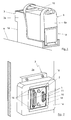
- Fig. 1
- eine perspektivische Darstellung einer ersten Einheit in Form eines Adapters mit einer eingesetzten zweiten Einheit in Form eines Flugdatenspeichers;
- Fig. 2
- eine Ansicht einer Steckeranordnung der ersten Einheit, wobei die Stecker mit einem ersten Trägerelement verschraubt sind, welches mit einer ersten Teilabschirmung versehen ist;
- Fig. 3
- eine Ansicht einer Buchsenanordnung der zweiten Einheit, wobei die Buchsen mit einem zweiten Trägerelement verschraubt sind, welches mit der zweiten Teilabschirmung versehen ist;
- Fig. 4
- eine prinzipmäßige Darstellung des ersten Trägerelementes in einer zu Fig. 2 alternativen Ausführungsform, wobei das erste Trägerelement schwimmend mit der ersten Einheit verbunden ist; und
- Fig. 5
- eine prinzipmäßige Darstellung in der die beiden Einheiten über Steckverbindungen miteinander verbunden sind und aus den Teilabschirmungen eine die Steckverbindungen elektromagnetisch abschirmende Abschirmeinrichtung gebildet ist.
Claims (21)
- Vorrichtung zur Erzeugung einer elektro-magnetisch abgeschirmten Verbindung zwischen einer wenigstens einen Stecker aufweisenden Steckeranordnung einer ersten Einheit und einer wenigstens eine korrespondierende Buchse aufweisenden Buchsenanordnung einer zweiten Einheit, wobei der wenigstens eine Stecker und die wenigstens eine Buchse in ihrem miteinander verbundenen Zustand eine Steckverbindung bilden,
dadurch gekennzeichnet , dass
die Steckverbindung (7) von einer dieselbe elektro-magnetisch dicht abschirmenden Abschirmeinrichtung (13) umgeben ist, welche von dem wenigstens einen Stecker (1) und der wenigstens einen Buchse (4) unabhängig ausgebildet ist. - Vorrichtung nach Anspruch 1,
dadurch gekennzeichnet, dass
die elektro-magnetische Abschirmeinrichtung (13) aus einer die Steckeranordnung (2) umgebenden ersten Teilabschirmung (11) und einer die Buchsenanordnung (5) umgebenden zweiten Teilabschirmung (12) zusammensetzbar ist. - Vorrichtung nach Anspruch 2,
dadurch gekennzeichnet, dass
die beiden Teilabschirmungen (11,12) elektro-magnetisch dicht miteinander kontaktieren, wenn der wenigstens eine Stecker (1) die wenigstens eine Buchse (4) kontaktiert. - Vorrichtung nach Anspruch 2 oder 3,
dadurch gekennzeichnet, dass
die erste Teilabschirmung (11) mit der ersten Einheit (3) und die zweite Teilabschirmung (12) mit der zweiten Einheit (6) elektro-magnetisch dicht verbunden ist. - Vorrichtung nach einem der Ansprüche 2 bis 4,
dadurch gekennzeichnet, dass
die erste Teilabschirmung (11) und/oder die zweite Teilabschirmung (12) als umlaufender Rand, Erhebung, Wulst oder Vorsprung ausgebildet ist. - Vorrichtung nach einem der Ansprüche 2 bis 5,
dadurch gekennzeichnet, dass
wenigstens eine Teilabschirmung (11,12) schwimmend bzw. flexibel mit der zugeordneten Einheit (3,6) verbunden ist. - Vorrichtung nach einem der Ansprüche 2 bis 6,
dadurch gekennzeichnet, dass
der wenigstens eine Stecker (1) mit einem ersten Trägerelement (14) verbunden ist, welches mit der ersten Teilabschirmung (11) versehen ist, und die wenigstens eine Buchse (4) mit einem zweiten Trägerelement (17) verbunden ist, welches mit der zweiten Teilabschirmung (12) versehen ist. - Vorrichtung nach Anspruch 7,
dadurch gekennzeichnet, dass
der wenigstens eine Stecker (1) mit dem ersten Trägerelement (14) und die wenigstens eine Buchse (4) mit dem zweiten Trägerelement (17) lösbar verbunden ist. - Vorrichtung nach Anspruch 7 oder 8,
dadurch gekennzeichnet, dass
der wenigstens eine Stecker (1) und/oder die wenigstens eine Buchse (4) schwimmend bzw. flexibel mit dem jeweiligen Trägerelement (14,17) verbunden ist. - Vorrichtung nach Ansprüche 7, 8 oder 9,
dadurch gekennzeichnet, dass
das erste Trägerelement (14) und das zweite Trägerelement (17) zur definierten Verbindung miteinander jeweils mit zueinander korrespondierenden Führungselementen (18,19) versehen sind. - Vorrichtung nach Anspruch 10,
dadurch gekennzeichnet, dass
das erste Trägerelement (14) Führungsstifte (18) und das zweite Trägerelement (17) Führungsbohrungen (19) aufweist. - Vorrichtung nach einem der Ansprüche 7 bis 11,
dadurch gekennzeichnet, dass
das erste Trägerelement (14) im wesentlichen plattenförmig ausgebildet und schwimmend mit der ersten Einheit (3) verbunden ist, wobei die erste Teilabschirmung (11) aus im wesentlichen linear verlaufenden Vorsprüngen (16) ausgebildet ist, welche im wesentlichen in Form eines Rechtecks zueinander angeordnet sind und die Steckeranordnung (2) umgeben. - Vorrichtung nach Anspruch 12,
dadurch gekennzeichnet, dass
das zweite Trägerelement (17) im wesentlichen plattenförmig ausgebildet und unbeweglich mit der zweiten Einheit (6) verbunden ist, wobei die zweite Teilabschirmung (12) als Plattenrand ausgebildet ist, welcher die Buchsenanordnung (5) umgibt. - Vorrichtung nach Anspruch 12 oder 13,
dadurch gekennzeichnet, dass
die Vorsprünge (16) des ersten Trägerelements (14) und/oder die als Plattenrand ausgebildete zweite Teilabschirmung (12) des zweiten Trägerelements (17) Kontaktfedern aufweisen und/oder als Kontaktfederausgebildet sind. - Vorrichtung nach einem der Ansprüche 1 bis 14,
dadurch gekennzeichnet, dass
die Steckeranordnung (2) jeweils wenigstens zwei Stecker (1) und die Buchsenanordnung (5) jeweils wenigstens zwei Buchsen (4) aufweist. - Vorrichtung nach einem der Ansprüche 2 bis 15,
dadurch gekennzeichnet, dass
die zu den Steckern (1) bzw. den Buchsen (4) führenden Kabel (20) eine metallische Ummantelung (21) aufweisen, die mit der jeweils zugeordneten Teilabschirmung (11,12) direkt oder über die zugeordneten Trägerelemente (14,17) bzw. die zugeordnete Einheit (3,6) elektro-magnetisch dicht verbunden bzw. verbindbar sind. - Vorrichtung nach einem der Ansprüche 2 bis 16,
dadurch gekennzeichnet, dass
der Innenraum der ersten Einheit (3) und/oder der zweiten Einheit (6) durch ein metallisches Gehäuse (3a,6a) elektro-magnetisch dicht abgeschirmt ist, wobei das metallische Gehäuse (3a,6a) mit der jeweils zugeordneten Teilabschirmung (11,12) elektro-magnetisch dicht verbunden bzw. verbindbar ist. - Vorrichtung nach einem der Ansprüche 1 bis 17,
dadurch gekennzeichnet, dass
die Stecker (1) bzw. die Buchsen (4) zur Hochfrequenzdatenübertragung vorgesehen sind. - Vorrichtung nach einem der Ansprüche 1 bis 18,
dadurch gekennzeichnet, dass
die Stecker (1) bzw. die Buchsen (4) hochpolig ausgebildet sind. - Vorrichtung nach einem der Ansprüche 1 bis 19,
dadurch gekennzeichnet, dass
die zweite Einheit (6) als portabler Flugdatenspeicher ausgebildet ist, auf den während eines Bildflugs eines Flugzeuges (8) von einer digitalen Kamera anfallende Daten ablegbar sind. - Vorrichtung nach Anspruch 20,
dadurch gekennzeichnet, dass
die erste Einheit (3) als ein zur Aufnahme des Flugdatenspeichers (6) geeigneter Adapter ausgebildet ist, wobei der Adapter elektrisch und/oder mechanisch mit dem Flugzeug (8) verbunden ist.
Applications Claiming Priority (2)
| Application Number | Priority Date | Filing Date | Title |
|---|---|---|---|
| DE102004013874 | 2004-03-20 | ||
| DE102004013874A DE102004013874A1 (de) | 2004-03-20 | 2004-03-20 | Vorrichtung zur Erzeugung einer elektro-magnetisch abgeschirmten Verbindung |
Publications (2)
| Publication Number | Publication Date |
|---|---|
| EP1578185A1 true EP1578185A1 (de) | 2005-09-21 |
| EP1578185B1 EP1578185B1 (de) | 2018-10-03 |
Family
ID=34833225
Family Applications (1)
| Application Number | Title | Priority Date | Filing Date |
|---|---|---|---|
| EP05002635.0A Expired - Lifetime EP1578185B1 (de) | 2004-03-20 | 2005-02-09 | Vorrichtung zur Erzeugung einer elektro-magnetisch abgeschirmten Verbindung |
Country Status (4)
| Country | Link |
|---|---|
| US (1) | US7147511B2 (de) |
| EP (1) | EP1578185B1 (de) |
| JP (1) | JP4776957B2 (de) |
| DE (1) | DE102004013874A1 (de) |
Cited By (1)
| Publication number | Priority date | Publication date | Assignee | Title |
|---|---|---|---|---|
| WO2011113940A3 (de) * | 2010-03-19 | 2012-02-02 | Magna Steyr Fahrzeugtechnik Ag & Co Kg | Kupplung zwischen einer wechselbaren batterie und einem fahrzeug |
Families Citing this family (7)
| Publication number | Priority date | Publication date | Assignee | Title |
|---|---|---|---|---|
| DE102004013875A1 (de) * | 2004-03-20 | 2005-11-17 | Z/I Imaging Ltd., Shannon | Vorrichtung zur Befestigung einer portablen elektronischen Einheit |
| DE102006050288B4 (de) * | 2006-10-23 | 2014-02-13 | Rittal Gmbh & Co. Kg | Leistungsversorgungseinrichtung |
| WO2015164538A1 (en) | 2014-04-23 | 2015-10-29 | Tyco Electronics Corporation | Electrical connector with shield cap and shielded terminals |
| CN104527616B (zh) * | 2014-12-05 | 2016-08-24 | 奇瑞新能源汽车技术有限公司 | 一种电池包快换机构及电动车 |
| JP6507135B2 (ja) * | 2016-03-15 | 2019-04-24 | 宏致電子股▲ふん▼有限公司Aces Electronics Co.,Ltd. | プラグユニット及びレセプタクルユニット |
| US10263365B2 (en) | 2016-03-15 | 2019-04-16 | Aces Electronics Co., Ltd. | Plug unit and receptacle unit |
| JP6871267B2 (ja) * | 2016-10-25 | 2021-05-12 | オリンパス株式会社 | 内視鏡プロセッサ |
Citations (6)
| Publication number | Priority date | Publication date | Assignee | Title |
|---|---|---|---|---|
| DE3432789A1 (de) * | 1983-09-07 | 1985-04-11 | Sundstrand Data Control, Inc., Redmond, Wash. | Waermeschutzgehaeuse |
| EP0351070A2 (de) * | 1988-07-15 | 1990-01-17 | Hewlett-Packard Company | Doppelwandiges Ablenkelement zur Belüftung und elektromagnetischen Abschirmung |
| EP0752808A1 (de) * | 1995-07-01 | 1997-01-08 | British Aerospace Public Limited Company | Wärme- und stossfestes Datenaufzeichnungsgerät |
| WO2000078113A1 (en) * | 1999-06-16 | 2000-12-21 | Ericsson, Inc. | Rf emissions shield including resilient fingers and connector assembly and method including the same |
| US20020012238A1 (en) * | 2000-07-31 | 2002-01-31 | Tsutomu Takahashi | Communication device and plug-in unit therefor |
| EP1398853A2 (de) * | 2002-09-12 | 2004-03-17 | Harting Electric GmbH & Co. KG | Steckverbindermodul |
Family Cites Families (11)
| Publication number | Priority date | Publication date | Assignee | Title |
|---|---|---|---|---|
| JPS6165789U (de) * | 1984-10-04 | 1986-05-06 | ||
| JP3300503B2 (ja) * | 1993-09-29 | 2002-07-08 | 株式会社日立国際電気 | フライトデータレコーダのオンラインモニタ装置と試験装置 |
| FR2742626B1 (fr) * | 1995-12-19 | 1998-02-20 | Eurocopter France | Dispositif de guidage, d'entrainement et de verrouillage d'un tiroir d'equipement electrique ou electronique dans une armoire |
| JPH10135678A (ja) * | 1996-10-30 | 1998-05-22 | Nec Corp | プラグインタイプ電子装置のシールド構造 |
| ATE309944T1 (de) * | 2000-02-03 | 2005-12-15 | Honeywell Int Inc | Auf ereignisse basierte flugzeugbildsequenz und daten-aufzeichnungssystem |
| US6305986B1 (en) * | 2000-05-18 | 2001-10-23 | Hon Hai Precision Ind. Co., Ltd. | Cable connector assembly having improved grounding means |
| FR2815778B1 (fr) * | 2000-10-23 | 2002-12-06 | Alstom | Dispositif de protection d'un connecteur electrique pour plaque de circuit imprime contre les perturbations electromagnetiques |
| US6706966B2 (en) * | 2001-03-19 | 2004-03-16 | L-3 Communications Corporation | Hardened voyage data recorder |
| JP4232356B2 (ja) * | 2001-06-12 | 2009-03-04 | 富士通株式会社 | 通信装置 |
| US6533612B1 (en) * | 2001-08-24 | 2003-03-18 | Wieson Electronic Co., Ltd. | Connector with improved positioning structure |
| JP3607241B2 (ja) * | 2001-10-29 | 2005-01-05 | 日本圧着端子製造株式会社 | 電気コネクタ |
-
2004
- 2004-03-20 DE DE102004013874A patent/DE102004013874A1/de not_active Withdrawn
-
2005
- 2005-02-09 EP EP05002635.0A patent/EP1578185B1/de not_active Expired - Lifetime
- 2005-03-18 US US11/084,560 patent/US7147511B2/en not_active Expired - Lifetime
- 2005-03-22 JP JP2005081663A patent/JP4776957B2/ja not_active Expired - Fee Related
Patent Citations (6)
| Publication number | Priority date | Publication date | Assignee | Title |
|---|---|---|---|---|
| DE3432789A1 (de) * | 1983-09-07 | 1985-04-11 | Sundstrand Data Control, Inc., Redmond, Wash. | Waermeschutzgehaeuse |
| EP0351070A2 (de) * | 1988-07-15 | 1990-01-17 | Hewlett-Packard Company | Doppelwandiges Ablenkelement zur Belüftung und elektromagnetischen Abschirmung |
| EP0752808A1 (de) * | 1995-07-01 | 1997-01-08 | British Aerospace Public Limited Company | Wärme- und stossfestes Datenaufzeichnungsgerät |
| WO2000078113A1 (en) * | 1999-06-16 | 2000-12-21 | Ericsson, Inc. | Rf emissions shield including resilient fingers and connector assembly and method including the same |
| US20020012238A1 (en) * | 2000-07-31 | 2002-01-31 | Tsutomu Takahashi | Communication device and plug-in unit therefor |
| EP1398853A2 (de) * | 2002-09-12 | 2004-03-17 | Harting Electric GmbH & Co. KG | Steckverbindermodul |
Cited By (1)
| Publication number | Priority date | Publication date | Assignee | Title |
|---|---|---|---|---|
| WO2011113940A3 (de) * | 2010-03-19 | 2012-02-02 | Magna Steyr Fahrzeugtechnik Ag & Co Kg | Kupplung zwischen einer wechselbaren batterie und einem fahrzeug |
Also Published As
| Publication number | Publication date |
|---|---|
| JP4776957B2 (ja) | 2011-09-21 |
| US20050208832A1 (en) | 2005-09-22 |
| DE102004013874A1 (de) | 2005-10-06 |
| EP1578185B1 (de) | 2018-10-03 |
| JP2005268806A (ja) | 2005-09-29 |
| US7147511B2 (en) | 2006-12-12 |
Similar Documents
| Publication | Publication Date | Title |
|---|---|---|
| DE102013210343B4 (de) | Zweistufige Kontaktgestaltung für ein Verbindungssystem bei Energieanwendungen | |
| DE202016104271U1 (de) | Steckverbindersystem | |
| EP2695249A1 (de) | Voreilende massekontaktierung mittels federelement | |
| DE102015015202B4 (de) | Steckverbinder und Stecksystem | |
| EP3493333B1 (de) | Elektrische steckverbindung zur datenübertragung | |
| DE102016108989A1 (de) | Steckkontaktset und Verfahren zum Prüfen einer Verrastung des Steckkontaktsets | |
| EP3849028A1 (de) | Steckverbinderanordnung und elektrischer steckverbinder | |
| EP1578185B1 (de) | Vorrichtung zur Erzeugung einer elektro-magnetisch abgeschirmten Verbindung | |
| DE102019121872A1 (de) | Hybridsteckverbinder | |
| DE102016121598A1 (de) | Basismodul und Luftfahrtcomputersystem mit dem Basismodul | |
| DE102016006775A1 (de) | Elektrische Steckverbindung | |
| DE19844281A1 (de) | Elektrisches Gerät mit mindestens einem Einschub | |
| DE2414021B2 (de) | Scharnier fuer eine loesbare mechanische verbindung zweier elektrischer einrichtungen | |
| DE102024137044A1 (de) | Riser-karte für den vertikalen einbau einer erweiterungskarte | |
| DE69724166T2 (de) | Einschub für elektronische Karten mit automatischem Einstecken und Trennen, Einschub und seine Aufnahmestruktur, Demontageverfahren von elektronischen Karten | |
| DE102019111880B4 (de) | Elektrisches Steckverbindungssystem | |
| WO2009140987A1 (de) | Gehäusemodul und modular aufgebautes automatisierungsgerät | |
| DE1949412A1 (de) | Chassis fuer elektronische Geraete | |
| DE3628113C2 (de) | ||
| EP0052785A1 (de) | Vorrichtung zum Lösen und Herausziehen eines Mehrleiterkabels aus einem Gehäuse | |
| EP1134850B1 (de) | Durchführungsadapter und Steckverbinder für einen Durchführungsadapter | |
| DE3123503A1 (de) | "loesbare optische steckerverbindung" | |
| DE102021123968A1 (de) | Integrierte Motorvorrichtung mit steckverbundener Motoreinheit und Servoantriebseinheit | |
| DE202018106611U1 (de) | Datenübertragungs- und/oder Ladekabel | |
| DE102025114524A1 (de) | Modularer Medienkonverter und modulares Industriesteckverbindersystem mit modularem Medienkonverter |
Legal Events
| Date | Code | Title | Description |
|---|---|---|---|
| PUAI | Public reference made under article 153(3) epc to a published international application that has entered the european phase |
Free format text: ORIGINAL CODE: 0009012 |
|
| AK | Designated contracting states |
Kind code of ref document: A1 Designated state(s): AT BE BG CH CY CZ DE DK EE ES FI FR GB GR HU IE IS IT LI LT LU MC NL PL PT RO SE SI SK TR |
|
| AX | Request for extension of the european patent |
Extension state: AL BA HR LV MK YU |
|
| RAP1 | Party data changed (applicant data changed or rights of an application transferred) |
Owner name: Z/I IMAGING LTD. |
|
| 17P | Request for examination filed |
Effective date: 20060217 |
|
| AKX | Designation fees paid |
Designated state(s): AT BE BG CH CY CZ DE DK EE ES FI FR GB GR HU IE IS IT LI LT LU MC NL PL PT RO SE SI SK TR |
|
| REG | Reference to a national code |
Ref country code: HK Ref legal event code: DE Ref document number: 1085604 Country of ref document: HK |
|
| 17Q | First examination report despatched |
Effective date: 20090902 |
|
| RAP1 | Party data changed (applicant data changed or rights of an application transferred) |
Owner name: LEICA GEOSYSTEMS AG |
|
| STAA | Information on the status of an ep patent application or granted ep patent |
Free format text: STATUS: EXAMINATION IS IN PROGRESS |
|
| GRAP | Despatch of communication of intention to grant a patent |
Free format text: ORIGINAL CODE: EPIDOSNIGR1 |
|
| STAA | Information on the status of an ep patent application or granted ep patent |
Free format text: STATUS: GRANT OF PATENT IS INTENDED |
|
| INTG | Intention to grant announced |
Effective date: 20180523 |
|
| GRAS | Grant fee paid |
Free format text: ORIGINAL CODE: EPIDOSNIGR3 |
|
| GRAA | (expected) grant |
Free format text: ORIGINAL CODE: 0009210 |
|
| STAA | Information on the status of an ep patent application or granted ep patent |
Free format text: STATUS: THE PATENT HAS BEEN GRANTED |
|
| AK | Designated contracting states |
Kind code of ref document: B1 Designated state(s): AT BE BG CH CY CZ DE DK EE ES FI FR GB GR HU IE IS IT LI LT LU MC NL PL PT RO SE SI SK TR |
|
| REG | Reference to a national code |
Ref country code: GB Ref legal event code: FG4D Free format text: NOT ENGLISH |
|
| REG | Reference to a national code |
Ref country code: CH Ref legal event code: EP Ref country code: AT Ref legal event code: REF Ref document number: 1050120 Country of ref document: AT Kind code of ref document: T Effective date: 20181015 |
|
| REG | Reference to a national code |
Ref country code: IE Ref legal event code: FG4D Free format text: LANGUAGE OF EP DOCUMENT: GERMAN Ref country code: DE Ref legal event code: R096 Ref document number: 502005015918 Country of ref document: DE |
|
| REG | Reference to a national code |
Ref country code: CH Ref legal event code: PK Free format text: BERICHTIGUNGEN |
|
| REG | Reference to a national code |
Ref country code: NL Ref legal event code: MP Effective date: 20181003 |
|
| RIC2 | Information provided on ipc code assigned after grant |
Ipc: H05K 9/00 20060101AFI20050725BHEP |
|
| REG | Reference to a national code |
Ref country code: LT Ref legal event code: MG4D |
|
| PG25 | Lapsed in a contracting state [announced via postgrant information from national office to epo] |
Ref country code: NL Free format text: LAPSE BECAUSE OF FAILURE TO SUBMIT A TRANSLATION OF THE DESCRIPTION OR TO PAY THE FEE WITHIN THE PRESCRIBED TIME-LIMIT Effective date: 20181003 |
|
| PG25 | Lapsed in a contracting state [announced via postgrant information from national office to epo] |
Ref country code: IS Free format text: LAPSE BECAUSE OF FAILURE TO SUBMIT A TRANSLATION OF THE DESCRIPTION OR TO PAY THE FEE WITHIN THE PRESCRIBED TIME-LIMIT Effective date: 20190203 Ref country code: FI Free format text: LAPSE BECAUSE OF FAILURE TO SUBMIT A TRANSLATION OF THE DESCRIPTION OR TO PAY THE FEE WITHIN THE PRESCRIBED TIME-LIMIT Effective date: 20181003 Ref country code: PL Free format text: LAPSE BECAUSE OF FAILURE TO SUBMIT A TRANSLATION OF THE DESCRIPTION OR TO PAY THE FEE WITHIN THE PRESCRIBED TIME-LIMIT Effective date: 20181003 Ref country code: CZ Free format text: LAPSE BECAUSE OF FAILURE TO SUBMIT A TRANSLATION OF THE DESCRIPTION OR TO PAY THE FEE WITHIN THE PRESCRIBED TIME-LIMIT Effective date: 20181003 Ref country code: LT Free format text: LAPSE BECAUSE OF FAILURE TO SUBMIT A TRANSLATION OF THE DESCRIPTION OR TO PAY THE FEE WITHIN THE PRESCRIBED TIME-LIMIT Effective date: 20181003 Ref country code: BG Free format text: LAPSE BECAUSE OF FAILURE TO SUBMIT A TRANSLATION OF THE DESCRIPTION OR TO PAY THE FEE WITHIN THE PRESCRIBED TIME-LIMIT Effective date: 20190103 Ref country code: ES Free format text: LAPSE BECAUSE OF FAILURE TO SUBMIT A TRANSLATION OF THE DESCRIPTION OR TO PAY THE FEE WITHIN THE PRESCRIBED TIME-LIMIT Effective date: 20181003 |
|
| PGFP | Annual fee paid to national office [announced via postgrant information from national office to epo] |
Ref country code: DE Payment date: 20190227 Year of fee payment: 15 |
|
| PG25 | Lapsed in a contracting state [announced via postgrant information from national office to epo] |
Ref country code: PT Free format text: LAPSE BECAUSE OF FAILURE TO SUBMIT A TRANSLATION OF THE DESCRIPTION OR TO PAY THE FEE WITHIN THE PRESCRIBED TIME-LIMIT Effective date: 20190203 Ref country code: GR Free format text: LAPSE BECAUSE OF FAILURE TO SUBMIT A TRANSLATION OF THE DESCRIPTION OR TO PAY THE FEE WITHIN THE PRESCRIBED TIME-LIMIT Effective date: 20190104 Ref country code: SE Free format text: LAPSE BECAUSE OF FAILURE TO SUBMIT A TRANSLATION OF THE DESCRIPTION OR TO PAY THE FEE WITHIN THE PRESCRIBED TIME-LIMIT Effective date: 20181003 |
|
| REG | Reference to a national code |
Ref country code: DE Ref legal event code: R097 Ref document number: 502005015918 Country of ref document: DE |
|
| PG25 | Lapsed in a contracting state [announced via postgrant information from national office to epo] |
Ref country code: DK Free format text: LAPSE BECAUSE OF FAILURE TO SUBMIT A TRANSLATION OF THE DESCRIPTION OR TO PAY THE FEE WITHIN THE PRESCRIBED TIME-LIMIT Effective date: 20181003 Ref country code: IT Free format text: LAPSE BECAUSE OF FAILURE TO SUBMIT A TRANSLATION OF THE DESCRIPTION OR TO PAY THE FEE WITHIN THE PRESCRIBED TIME-LIMIT Effective date: 20181003 |
|
| PLBE | No opposition filed within time limit |
Free format text: ORIGINAL CODE: 0009261 |
|
| STAA | Information on the status of an ep patent application or granted ep patent |
Free format text: STATUS: NO OPPOSITION FILED WITHIN TIME LIMIT |
|
| PG25 | Lapsed in a contracting state [announced via postgrant information from national office to epo] |
Ref country code: RO Free format text: LAPSE BECAUSE OF FAILURE TO SUBMIT A TRANSLATION OF THE DESCRIPTION OR TO PAY THE FEE WITHIN THE PRESCRIBED TIME-LIMIT Effective date: 20181003 Ref country code: SK Free format text: LAPSE BECAUSE OF FAILURE TO SUBMIT A TRANSLATION OF THE DESCRIPTION OR TO PAY THE FEE WITHIN THE PRESCRIBED TIME-LIMIT Effective date: 20181003 Ref country code: EE Free format text: LAPSE BECAUSE OF FAILURE TO SUBMIT A TRANSLATION OF THE DESCRIPTION OR TO PAY THE FEE WITHIN THE PRESCRIBED TIME-LIMIT Effective date: 20181003 |
|
| 26N | No opposition filed |
Effective date: 20190704 |
|
| REG | Reference to a national code |
Ref country code: CH Ref legal event code: PL |
|
| GBPC | Gb: european patent ceased through non-payment of renewal fee |
Effective date: 20190209 |
|
| PG25 | Lapsed in a contracting state [announced via postgrant information from national office to epo] |
Ref country code: LU Free format text: LAPSE BECAUSE OF NON-PAYMENT OF DUE FEES Effective date: 20190209 Ref country code: SI Free format text: LAPSE BECAUSE OF FAILURE TO SUBMIT A TRANSLATION OF THE DESCRIPTION OR TO PAY THE FEE WITHIN THE PRESCRIBED TIME-LIMIT Effective date: 20181003 Ref country code: MC Free format text: LAPSE BECAUSE OF FAILURE TO SUBMIT A TRANSLATION OF THE DESCRIPTION OR TO PAY THE FEE WITHIN THE PRESCRIBED TIME-LIMIT Effective date: 20181003 |
|
| REG | Reference to a national code |
Ref country code: BE Ref legal event code: MM Effective date: 20190228 |
|
| REG | Reference to a national code |
Ref country code: IE Ref legal event code: MM4A |
|
| PG25 | Lapsed in a contracting state [announced via postgrant information from national office to epo] |
Ref country code: LI Free format text: LAPSE BECAUSE OF NON-PAYMENT OF DUE FEES Effective date: 20190228 Ref country code: CH Free format text: LAPSE BECAUSE OF NON-PAYMENT OF DUE FEES Effective date: 20190228 |
|
| PG25 | Lapsed in a contracting state [announced via postgrant information from national office to epo] |
Ref country code: IE Free format text: LAPSE BECAUSE OF NON-PAYMENT OF DUE FEES Effective date: 20190209 Ref country code: GB Free format text: LAPSE BECAUSE OF NON-PAYMENT OF DUE FEES Effective date: 20190209 |
|
| PG25 | Lapsed in a contracting state [announced via postgrant information from national office to epo] |
Ref country code: BE Free format text: LAPSE BECAUSE OF NON-PAYMENT OF DUE FEES Effective date: 20190228 Ref country code: FR Free format text: LAPSE BECAUSE OF NON-PAYMENT OF DUE FEES Effective date: 20190228 |
|
| PG25 | Lapsed in a contracting state [announced via postgrant information from national office to epo] |
Ref country code: TR Free format text: LAPSE BECAUSE OF FAILURE TO SUBMIT A TRANSLATION OF THE DESCRIPTION OR TO PAY THE FEE WITHIN THE PRESCRIBED TIME-LIMIT Effective date: 20181003 |
|
| REG | Reference to a national code |
Ref country code: AT Ref legal event code: MM01 Ref document number: 1050120 Country of ref document: AT Kind code of ref document: T Effective date: 20190209 |
|
| PG25 | Lapsed in a contracting state [announced via postgrant information from national office to epo] |
Ref country code: AT Free format text: LAPSE BECAUSE OF NON-PAYMENT OF DUE FEES Effective date: 20190209 |
|
| REG | Reference to a national code |
Ref country code: DE Ref legal event code: R119 Ref document number: 502005015918 Country of ref document: DE |
|
| REG | Reference to a national code |
Ref country code: HK Ref legal event code: WD Ref document number: 1085604 Country of ref document: HK |
|
| PG25 | Lapsed in a contracting state [announced via postgrant information from national office to epo] |
Ref country code: DE Free format text: LAPSE BECAUSE OF NON-PAYMENT OF DUE FEES Effective date: 20200901 |
|
| PG25 | Lapsed in a contracting state [announced via postgrant information from national office to epo] |
Ref country code: CY Free format text: LAPSE BECAUSE OF FAILURE TO SUBMIT A TRANSLATION OF THE DESCRIPTION OR TO PAY THE FEE WITHIN THE PRESCRIBED TIME-LIMIT Effective date: 20181003 |
|
| PG25 | Lapsed in a contracting state [announced via postgrant information from national office to epo] |
Ref country code: HU Free format text: LAPSE BECAUSE OF FAILURE TO SUBMIT A TRANSLATION OF THE DESCRIPTION OR TO PAY THE FEE WITHIN THE PRESCRIBED TIME-LIMIT; INVALID AB INITIO Effective date: 20050209 |