EP1577895A2 - Vorrichtung zur Halterung eines Speichermediums - Google Patents
Vorrichtung zur Halterung eines Speichermediums Download PDFInfo
- Publication number
- EP1577895A2 EP1577895A2 EP05002637A EP05002637A EP1577895A2 EP 1577895 A2 EP1577895 A2 EP 1577895A2 EP 05002637 A EP05002637 A EP 05002637A EP 05002637 A EP05002637 A EP 05002637A EP 1577895 A2 EP1577895 A2 EP 1577895A2
- Authority
- EP
- European Patent Office
- Prior art keywords
- support structure
- storage medium
- housing
- pressure
- outside
- Prior art date
- Legal status (The legal status is an assumption and is not a legal conclusion. Google has not performed a legal analysis and makes no representation as to the accuracy of the status listed.)
- Granted
Links
Images


Classifications
-
- G—PHYSICS
- G11—INFORMATION STORAGE
- G11B—INFORMATION STORAGE BASED ON RELATIVE MOVEMENT BETWEEN RECORD CARRIER AND TRANSDUCER
- G11B33/00—Constructional parts, details or accessories not provided for in the other groups of this subclass
- G11B33/02—Cabinets; Cases; Stands; Disposition of apparatus therein or thereon
- G11B33/04—Cabinets; Cases; Stands; Disposition of apparatus therein or thereon modified to store record carriers
- G11B33/0405—Cabinets; Cases; Stands; Disposition of apparatus therein or thereon modified to store record carriers for storing discs
- G11B33/0433—Multiple disc containers
- G11B33/0455—Multiple disc containers for single disc boxes
-
- G—PHYSICS
- G11—INFORMATION STORAGE
- G11B—INFORMATION STORAGE BASED ON RELATIVE MOVEMENT BETWEEN RECORD CARRIER AND TRANSDUCER
- G11B33/00—Constructional parts, details or accessories not provided for in the other groups of this subclass
- G11B33/02—Cabinets; Cases; Stands; Disposition of apparatus therein or thereon
- G11B33/04—Cabinets; Cases; Stands; Disposition of apparatus therein or thereon modified to store record carriers
- G11B33/0405—Cabinets; Cases; Stands; Disposition of apparatus therein or thereon modified to store record carriers for storing discs
- G11B33/0433—Multiple disc containers
- G11B33/0438—Multiple disc containers for disc cartridges
Definitions
- the invention relates to a device for mounting at least one storage medium.
- a device for arranging a storage medium for example a mass storage in the form of a hard disk, known in which the storage medium in a introduced connected to a housing holder becomes.
- shocks and vibrations are disturbing the storage medium, inasmuch as the to the Reading or writing the storage medium provided Hard disk head is in a parking position.
- vibrations or shocks too damage or destruction of the storage medium to lead.
- Shocks and vibrations can be different Have causes and in the most diverse Applications occur. Regularly is with it such loads to be expected when the storage medium Used in land, water or air vehicles in which, during a movement of the same written on the storage medium or information have to be read from the storage medium.
- Such special hard disks are in particular also then used when it comes to the storage medium is about a flight data storage on the during a picture flight large amounts of data of a digital camera should be stored.
- this data it can e.g. image data, supplementary data for the images, such as. Mission data, system information or general information for post processing.
- the storage medium is in this case generally as mass storage designed for "digital mapping camera".
- each storage unit is mechanically fastened and electrically with all necessary cables connected. Electrical and mechanical is every flight data memory an independent entity that has one Image data port connected to a digital camera is. Furthermore, a control data input, a Control data output and a supply voltage input, a supply voltage output as well serial port available for configuration.
- the flight data memory stores the image data during of the flight. After landing, the flight data storage becomes taken and the image data on terrestrial mass storage copied. After copying and a subsequent Formatting is the flight data store again free for further image flights.
- the present invention is therefore the task based, a device for holding at least to create a storage medium, the aforementioned Disadvantages of the prior art triggers, in the the storage medium especially against vibration and Shocks as well as pressure fluctuations and excessive heat development is protected.
- the storage medium is arranged in a support structure which is vibration damped by a damping device with a surrounding the support structure Housing is connected, wherein the storage medium pressure-tight delimited to an outside atmosphere and a Cooling element provided for cooling the storage medium is.
- the storage medium By the inventive arrangement of the storage medium this is against vibration, vibrations and Shock protected.
- the storage medium can be considered relative simple and inexpensive standard hard drive be educated. A special and therefore cost-effective Special production of the hard disk or the Write and / or read inserted hard disk head is not necessary.
- the storage medium Vibration-damped via a supporting structure is, the storage medium can be exchanged in a simple manner be without the entire damping device must be dismantled.
- the damping device and the support structure can also change the Storage medium or in a repair-related or a capacity-related exchange unchanged remain. It is advantageous if the damping device is designed dynamically.
- the storage medium according to the invention pressure-tight is delimited to an outside atmosphere, prevents any change of altitude, for example when used in an airplane, the Pressure in the area of the storage medium drops and itself thus possibly setting a pressure which is a correct one Work of the storage medium no longer permits.
- the solution according to the invention is also the when using a storage medium regularly occurring problem of cooling or the discharge of the resulting from the use of the storage medium Heat, dissolved.
- a cooling element is used, the storage medium, which pressure-tight to a Outside atmosphere is delimited, cool.
- the to Outside atmosphere pressure-tight arrangement of the storage medium is a cooling of the same particularly important because otherwise overheating and thus damage the storage medium is not reliably excluded can be.
- the device according to the invention can also several storage media are recorded. You can do this For example, several hard disk drives mechanically and electrically to an easily exchangeable unit summarized and arranged in a support structure become. Alternatively, it is also possible within a housing to arrange a plurality of support structures.
- the support structure also for receiving electrical system components, such as Power supply, interfaces, controllers or RAID controllers etc. is used.
- electrical system components such as Power supply, interfaces, controllers or RAID controllers etc.
- the device according to the invention is particularly suitable Way, if the storage medium as an ingredient a flight data memory in an aircraft for storage the image data or other data used becomes. It is advantageous if the housing is inside whose arranged the support structure with the storage medium is, with means of attachment to one with an aircraft connected adapter is formed.
- An embodiment of the housing for attachment to a Adapter has been found to be particularly suitable to the inventive device in a simple Way in different types of aircraft to use can.
- the adapter can be fixed to the plane be connected so that the inventive device or the housing receives a corresponding guide.
- a shockproof or vibration protected arrangement of the housing is not necessary because the occurring shocks and vibrations by the damping device between the support structure and the housing be absorbed. It is an advantage if the housing has coupling elements which are intended for Transmission and / or reception of signals and / or a supply voltage with coupling elements of Adapters are connectable.
- the support structure in which the storage medium is arranged, pressure-tight train.
- the support structure as pressure-resistant or pressure-tight Housing is formed.
- the storage medium is thus easily sealed in a pressure-tight manner and is thus independent against pressure fluctuations, for example occur when an airplane's altitude replaced.
- the support structure has means that allow defined opening of the same to (if the outside atmosphere has a higher pressure level as the interior of the support structure) air into the support structure to flow because in principle, despite a pressure-tight design of the support structure a certain Pressure loss between the support structure and the outside atmosphere can not be excluded. According to experience flows when used at high altitudes more air per unit of time from the supporting structure than in the phase at the bottom flows back, because the pressure differences are different. Too low internal pressure can by a defined opening the Support structure can be counteracted.
- the storage medium may be affected by the general Prior art known dry cartridges be used.
- a pressure-tight design of the support structure can be provided that the controller on the outside the support structure is arranged.
- controller and other system components also within the pressure-tight support structure be arranged.
- this is only for such System components useful, the pressure stability need or for which they are worth mentioning Way advantageous.
- a constructive embodiment of the invention can also be provided that between the inside the support structure and the storage medium heat conducting elements are arranged.
- the through the storage medium Heat generated by the heat-conducting elements in a simple way fast and reliable too derived from the supporting structure.
- the heat-conducting elements can be designed for example as Leitmatten be.
- the cooling element arranged such or is used that the cooling element mainly for cooling the outside of the support structure and / or the controller or other system components serves. It can be provided that the cooling element is designed as a fan, the Air from outside the housing into the housing brings or sucks. The housing can be used for convection with the outside atmosphere air vents exhibit. As advantageous has also the Use of air baffles exposed that the Support structure or the controller and / or other system components surrounded and those generated by the fan Allow the air flow to flow past it.
- the fabric can be used, for example, as textile fabric be trained and prevents the fan promotes the airflow into areas he does not is effective. By covering the air flow can be directed to the areas where one Heat dissipation is necessary.
- a constructive embodiment of the invention may alternatively to the pressure-tight embodiment of Support structure also be provided that the housing is formed pressure-tight.
- the support structure can do this be designed such that a circulation of the in the housing sealed gaseous medium (e.g. Air) to the storage medium is possible. This acts it is an embodiment that is for certain Applications may seem advantageous.
- a disadvantage of the pressure-tight design the case is that no cool outside air used for direct cooling of the heat-generating elements can be.
- the cooling in the pressure-tight Housing contained system component can only passively, by applying heat give the pressure-tight housing and the heat from the pressure tight housing subsequently to the outside environment is derived.
- the cooling can be improved when inside the pressure-tight housing Cooling element, for example designed as a fan, is arranged.
- the cooling element can be used for circulation the gaseous medium within the pressure-resistant Housing can be used, reducing heat dissipation is improved in the housing.
- a Covering preferably a textile covering used be so inside the pressure-tight housing essentially the heat-generating system components, preferably the storage medium through which Cooling fan.
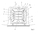
- Fig. 1 shows the device according to the invention for mounting at least one storage medium 1.
- the storage medium 1 is designed as a hard disk storage. Of the Hard disk space is used during the Image flight data captured by a digital camera store. Digital cameras for recording such Data is sufficient from the general state of the art known, why in the embodiment of this will not be discussed in detail.
- the device according to the invention is used in the most diverse areas where a reliable Writing or reading data to or from a storage medium is required.
- the device according to the invention is suitable thereby in the ranges of the technology with which the storage medium while reading or writing bumps, Vibrations or vibrations and / or pressure fluctuations is exposed.
- the exemplary embodiment shows an example of the application of a flight data storage, which is for recording used by image data in an aircraft.
- the storage medium is commercially available Hard disk 1 formed.
- the hard disk is 1 arranged in a support structure 2, which via a Damping device 3 vibration damped with a the supporting structure 2 surrounding housing 4 is connected.
- the hard disk 1 is pressure tight to a not delimited outer atmosphere defined.
- a cooling element 5 is provided.
- the pressure-tight or pressure-insulated arrangement of Hard disk 1 is realized according to FIG. 1, that the support structure 2 is formed pressure-tight.
- the support structure 2 has an interior, the essentially the dimensions of the hard disk 1 equivalent. It is envisaged that between the Inside of the support structure 2 and the hard disk 1 Heat-conducting elements 6 are arranged. According to FIG. 1 the heat-conducting elements thereby formed as Leitmatten 6.
- the resulting from the operation of the hard disk 1 Temperature is thus fast on the Leitmatten 6 and reliably transported away and into the supporting structure 2 initiated. From the support structure 2 radiates the absorbed heat to the outside. To a fast Heat removal from the surface of the support structure 2 to support, has the support structure 2 on its outside Cooling ribs 7, which correspond to the surface enlarge.
- the cooling element 5 is substantially the Cooling of the outside of the support structure 2 is provided.
- the cooling element is designed as a fan 5, which is fixed to the housing 4.
- the fan 5 refers its air necessary for ventilation from the outside atmosphere outside the housing 4. From the fan 5 the tightened air is directed towards the support structure 2 promoted or ventilated, so the air on the largest possible surface of the support structure 2 flows past.
- For convection with the outside atmosphere has the housing 4 in addition to the suction port for the fan 5 air passage openings 8.
- a textile fabric 9 is provided to Control of the air flow between the fan 5 and the support structure 2 .
- the textile fabric 9 is such spanned that the support structure 2 in the midst of the fan 5 generated air flow is.
- the textile covering 9 has the one shown in FIG Embodiment baffles 10, the from the fan 5 generated airflow 2 also accordingly channeled past the support structure 2 should. It is provided according to FIG. 1, that the textile covering 9 between the fan 5 and the Baffles 10 is clamped.
- the baffles 10 may be attached to the cooling fins 7 of the support structure 2 abut or adjoin them, so that through the baffles 10 and the cooling fins 7 channels be created by the generated by the fan 5 Air for cooling the outside of the support structure 2 can flow.
- a controller 11 is arranged on the outside of the support structure 2, a controller 11 is arranged. additionally to the controller 11 can not in closer shown way also other system components the outside of the support structure 2 may be arranged.
- the System components can also be used in pressure-sealed interior be arranged the support structure 2, if this appears to be advantageous for their functionality.
- the controller 11 is thus within one from the baffles 10 limited large air duct arranged.
- a possible way of airflow is represented in principle in Fig. 1.
- FIG Damping device 3 a plurality of vibration isolators 3a on.
- the vibration isolators are as am Market available wire rope vibration damper 3a formed. These wire rope vibration absorbers 3a are arranged such that the hard disk 1 or the support structure 2 suspended within the housing 4 is.
- the Housing 4 means 12 for attachment to a with a Aircraft connected adapter 13.
- the housing 4 has coupling elements for transmission / to Receiving signals and / or a Supply voltage with coupling elements of the adapter 13 are connectable.
- Fig. 1 it is provided that the fan 5 a Air filter 14 has to clean the sucked air.
- FIG. 2 shows an illustration of the support structure 2 the outside of eight wire rope vibration damper 3a for vibration or vibration damped connection provided with a housing 4, not shown in Fig. 2 are.
- the controller 11 is arranged on an outer side of the support structure 2 in this case.
- the support structure 2 cooling fins 7 on.
- the support structure 2 as well the controller 11 are comprised of two baffles 10, so in combination with the cooling fins 7 corresponding Cooling channels are created through which the air conveyed by the fan 5 (not shown in FIG. 2) can flow.
- Fig. 3 shows a view of the support structure 2 according to Fig. 2, wherein one half of the support structure 2 removed was, so the interior of the support structure 2 in principle is shown.
- Embodiment are in the interior of the support structure 2 two hard drives 1 arranged.
- the hard disks 1 are arranged such that the largest possible area of hard drives 1 with the cooling fins 7 provided outside of the support structure 2 faces.
- Between the hard disks 1 and the inside of the support structure 2 are the already mentioned Heat-conducting elements 6 arranged in the form of Leitmatten.
- the support structure 2 is essentially of two halves formed by a plurality of screws can be connected to each other.
- the two halves the support structure 2 are essentially as Half shells formed. Between the two half shells the support structure 2 is the arrangement of a seal 15 to provide.
- a sufficiently pressure-tight Support structure 2 formed in which the two Hard disks 1 can be arranged.
- Fig. 4 shows a possible embodiment of the housing 4 and the adapter 13.
- the means 12 for connecting the housing 4 with the adapter 13 by a lever 12 is formed through which the housing 4 in the adapter 13 can be clamped. Possibly can the lever 12 thereby by further fasteners or locking members are supported.
- the Case is with an outside mounted handle 16 provided by the housing 4 in a simple manner used in the adapter 13 and again from this can be removed.
- Such a design is particularly suitable for use of the Device according to the invention in an aircraft Recording image data as such devices often need to be removed to allow the hard drives 1 can be read.
- FIG. 5 shows an alternative to Fig. 1 embodiment.
- the in Fig. 5 and Fig. 1 with the same reference numerals designated elements have the same function and are with the exception of the following deviations analog or identical.
- the support structure 2 has an embodiment, which completed a circulation in the housing 4 gaseous medium (for example, air) around the hard disk 1 allows. It is also planned that the further system elements arranged in the housing 4, for example, the controller 11 through the circulation of the sealed in the housing 4 gaseous Medium to be cooled. In the housing 4 is arranged a cooling element 5, which is designed as a fan is. Within the housing 4 is also analog to Fig. 1, a textile fabric 9 is provided, the control the circulation of the gaseous medium so is intended that all possible contained in the housing 4 Elements - especially the hard disk 1 - the one to Heat development tend to be circulated or cooled.
- gaseous medium for example, air
- the fan 5 is shown in FIG. 5 on the outside of the Support structure 2 arranged such that the fan. 5 the gaseous medium is active from the interior of the Support structure 2, in which the hard disks 1 arranged are, sucks.
- the textile fabric 9 is the sucked from the interior of the support structure 2 gaseous Medium diverted and to a fan 5 directed opposite region of the support structure 2.
- the gaseous Medium for cooling the disks 1 back in the Interior of the support structure 2 flow.
- a principle possible and advantageous flow path is in Fig. 5 represented by the arrows.
- the solution according to the invention is particularly suitable Way for pressure-insulated and vibration-dampened fastening from storage media.
- other system elements may have a Such a holder is advantageous instead of Storage media used in the inventive solution become.
Landscapes
- Cooling Or The Like Of Electrical Apparatus (AREA)
- Vibration Prevention Devices (AREA)
- Packaging For Recording Disks (AREA)
Abstract
Description
- Fig. 1
- eine prinzipmäßige Darstellung der erfindungsgemäßen Vorrichtung mit einem Speicherelement, das innerhalb einer druckdicht ausgebildeten Tragstruktur angeordnet ist;
- Fig. 2
- eine perspektivische Darstellung der Tragstruktur mit einem an der Außenseite befestigten Controller, Luftleitbleichen und einer Dämpfungseinrichtung zur Befestigung an einem nicht dargestellten Gehäuse;
- Fig. 3
- eine Innenansicht der Tragstruktur mit zwei als Festplatten ausgebildeten Speichermedien;
- Fig. 4
- eine perspektivische Darstellung eines Adapters in welchem ein Gehäuse der erfindungsgemäßen Vorrichtung eingesetzt ist, und
- Fig. 5
- eine zu Fig. 1 alternative Ausgestaltung der erfindungsgemäßen Lösung, wobei das Gehäuse druckdicht ausgebildet ist.
Claims (20)
- Vorrichtung zur Halterung wenigstens eines Speichermediums,
dadurch gekennzeichnet , dass
das Speichermedium (1) in einer Tragstruktur (2) angeordnet ist, welche über eine Dämpfungseinrichtung (3) schwingungsgedämpft mit einem die Tragstruktur (2) umgebenden Gehäuse (4) verbunden ist, wobei das Speichermedium (1) druckdicht zu einer Außenatmosphäre abgegrenzt und ein Kühlelement (5) zur Kühlung des Speichermediums (1) vorgesehen ist. - Vorrichtung nach Anspruch 1,
dadurch gekennzeichnet , dass
ein Controller (11) an der Tragstruktur (2) angeordnet ist. - Vorrichtung nach Anspruch 1 oder 2,
dadurch gekennzeichnet , dass
die Dämpfungseinrichtung (3) eine Mehrzahl an Schwingungsisolatoren (3a) aufweist. - Vorrichtung nach Anspruch 3,
dadurch gekennzeichnet , dass
die Schwingungsisolatoren als Drahtseil-Schwingungsdämpfer (3a) ausgebildet sind. - Vorrichtung nach einem der Ansprüche 1 bis 4,
dadurch gekennzeichnet , dass
das Gehäuse (4) mit Mitteln (12) zur Befestigung an einem mit einem Flugzeug verbundenen Adapter (13) ausgebildet ist. - Vorrichtung nach Anspruch 5,
dadurch gekennzeichnet , dass
das Gehäuse (4) Kupplungselemente aufweist, die zur Übertragung/zum Empfang von Signalen und/oder einer Versorgungsspannung mit Kupplungselementen des Adapters (13) verbindbar sind. - Vorrichtung nach einem der Ansprüche 1 bis 6,
dadurch gekennzeichnet , dass
die Tragstruktur (2), in der das Speichermedium (1) angeordnet ist, druckdicht ausgebildet ist. - Vorrichtung nach Anspruch 2 und 7,
dadurch gekennzeichnet , dass
der Controller (11) an der Außenseite der Tragstruktur (2) angeordnet ist. - Vorrichtung nach Anspruch 7 oder 8,
dadurch gekennzeichnet , dass
zwischen der Innenseite der Tragstruktur (2) und dem Speichermedium (1) Wärmeleitelemente (6) angeordnet sind. - Vorrichtung nach Anspruch 9,
dadurch gekennzeichnet , dass
die Wärmeleitelemente als Leitmatten (6) ausgebildet sind. - Vorrichtung nach einem der Ansprüche 7 bis 10,
dadurch gekennzeichnet , dass
die Außenseite der Tragstruktur (2) mit Kühlrippen (7) versehen ist. - Vorrichtung nach einem der Ansprüche 1 bis 11,
dadurch gekennzeichnet , dass
das Kühlelement (5) zur Kühlung der Außenseite der Tragstruktur (2) und/oder des Controllers bzw. weiterer Systembestandteile dient. - Vorrichtung nach einem der Ansprüche 1 bis 12,
dadurch gekennzeichnet , dass
das Gehäuse (4) zur Konvektion mit der Außenatmosphäre Luftdurchgangsöffnungen (8) aufweist. - Vorrichtung nach einem der Ansprüche 1 bis 13,
dadurch gekennzeichnet , dass
das Kühlelement als Lüfter (5) ausgebildet ist, der Luft von außerhalb des Gehäuses in das Gehäuse (4) einbringt. - Vorrichtung nach Anspruch 14,
dadurch gekennzeichnet , dass
zur Steuerung des Luftstroms zwischen dem Lüfter (5) und der Tragstruktur (2) eine Bespannung (9) vorgesehen ist. - Vorrichtung nach einem der Ansprüche 7 bis 15,
dadurch gekennzeichnet , dass
der von der Tragstruktur (2) ausgebildete Innenraum im wesentlichen an die Form des Speichermediums (1) angepasst ist. - Vorrichtung nach einem der Ansprüche 1 bis 6,
dadurch gekennzeichnet , dass
das Gehäuse (4) druckdicht ausgebildet ist. - Vorrichtung nach Anspruch 17,
dadurch gekennzeichnet , dass
die Tragstruktur (2) eine Zirkulation des im Gehäuse (4) abgeschlossenen gasförmigen Mediums um das Speichermedium (1) ermöglicht. - Vorrichtung nach Anspruch 17 oder 18,
dadurch gekennzeichnet , dass
das Kühlelement (5) innerhalb des Gehäuses (4) angeordnet und als Lüfter ausgebildet ist. - Vorrichtung nach Anspruch 17, 18 oder 19,
dadurch gekennzeichnet , dass
zur Steuerung der Zirkulation des gasförmigen Mediums eine Bespannung (9) vorgesehen ist.
Applications Claiming Priority (2)
| Application Number | Priority Date | Filing Date | Title |
|---|---|---|---|
| DE102004013876 | 2004-03-20 | ||
| DE102004013876A DE102004013876A1 (de) | 2004-03-20 | 2004-03-20 | Vorrichtung zur Halterung eines Speichermediums |
Publications (3)
| Publication Number | Publication Date |
|---|---|
| EP1577895A2 true EP1577895A2 (de) | 2005-09-21 |
| EP1577895A3 EP1577895A3 (de) | 2008-01-23 |
| EP1577895B1 EP1577895B1 (de) | 2017-09-20 |
Family
ID=34833227
Family Applications (1)
| Application Number | Title | Priority Date | Filing Date |
|---|---|---|---|
| EP05002637.6A Expired - Lifetime EP1577895B1 (de) | 2004-03-20 | 2005-02-09 | Vorrichtung zur Halterung eines Speichermediums |
Country Status (5)
| Country | Link |
|---|---|
| US (1) | US7353527B2 (de) |
| EP (1) | EP1577895B1 (de) |
| JP (1) | JP5041670B2 (de) |
| DE (1) | DE102004013876A1 (de) |
| ES (1) | ES2650991T3 (de) |
Cited By (2)
| Publication number | Priority date | Publication date | Assignee | Title |
|---|---|---|---|---|
| GB2430540B (en) * | 2004-09-17 | 2009-07-15 | Xyratex Tech Ltd | Housings and devices for disk drives |
| CN112576684A (zh) * | 2020-11-27 | 2021-03-30 | 王文举 | 一种中央空调专用的具有减震防震功能的装置 |
Families Citing this family (11)
| Publication number | Priority date | Publication date | Assignee | Title |
|---|---|---|---|---|
| US7752775B2 (en) | 2000-03-10 | 2010-07-13 | Lyden Robert M | Footwear with removable lasting board and cleats |
| DE102004011680B4 (de) | 2004-03-10 | 2007-08-23 | Adidas International Marketing B.V. | Stollenschuh |
| DE102004013875A1 (de) * | 2004-03-20 | 2005-11-17 | Z/I Imaging Ltd., Shannon | Vorrichtung zur Befestigung einer portablen elektronischen Einheit |
| WO2007076565A1 (en) * | 2006-01-03 | 2007-07-12 | Continuum Audio Labs Pty Ltd | Vibration isolation assembly |
| JP2008262628A (ja) * | 2007-04-11 | 2008-10-30 | Hiroshi Miyoshi | ハードディスク等情報記録装置の騒音を遮断する収容箱 |
| DE102008018094A1 (de) | 2008-04-09 | 2009-10-15 | Kolt Engineering Gmbh | Dämpfungsanordnung |
| US20100051778A1 (en) * | 2008-09-03 | 2010-03-04 | Albert Taan Wu | Controlled Space with Anti-Shock Function for Automotive Electronics |
| US8934194B2 (en) * | 2011-01-09 | 2015-01-13 | Erhard Schreck | System and method for maintaining a low density gas environment in a disk drive |
| JP2015195069A (ja) | 2014-03-31 | 2015-11-05 | 富士通株式会社 | ストレージ装置、ストレージ装置の製造方法及びその測定方法 |
| CN108869631A (zh) * | 2018-09-18 | 2018-11-23 | 郑州讯轨通信科技有限公司 | 一种减震型物联网通信机箱 |
| CN112268399B (zh) * | 2020-09-24 | 2022-02-01 | 康帅冷链设备科技江苏有限公司 | 一种冷库热处理冷风机组 |
Family Cites Families (20)
| Publication number | Priority date | Publication date | Assignee | Title |
|---|---|---|---|---|
| US4831476A (en) * | 1985-07-15 | 1989-05-16 | Allen-Bradley Company | Disc drive isolation system |
| US4937806A (en) * | 1988-02-12 | 1990-06-26 | Mdb Systems, Inc. | Shock-isolated portable mass data storage device |
| JPH0739967Y2 (ja) * | 1989-11-22 | 1995-09-13 | 株式会社間組 | 石張り工用建設機械 |
| JP3716453B2 (ja) * | 1995-05-31 | 2005-11-16 | ソニー株式会社 | ディスクプレーヤ装置 |
| JPH09153277A (ja) * | 1995-11-29 | 1997-06-10 | Hitachi Ltd | 情報記録再生装置 |
| DE29610411U1 (de) * | 1996-06-13 | 1996-08-14 | Siemens AG, 80333 München | Elektronisches Gerät mit Massenspeicher |
| JPH10320709A (ja) * | 1997-05-20 | 1998-12-04 | Sony Corp | 磁気テープ内蔵式記録再生装置 |
| JP3456131B2 (ja) * | 1997-12-02 | 2003-10-14 | 松下電器産業株式会社 | スピーカ |
| US6002588A (en) * | 1997-12-04 | 1999-12-14 | Lockheed Martin Corporation | Thermally conductive vibration isolators |
| JP2000034682A (ja) * | 1998-07-13 | 2000-02-02 | Nec Eng Ltd | 被移動体駆動用ワイヤ |
| US6289678B1 (en) * | 1998-12-03 | 2001-09-18 | Phoenix Group, Inc. | Environmental system for rugged disk drive |
| EP1163570A4 (de) * | 1999-02-19 | 2007-12-19 | Gen Dynamics Inf Systems Inc | Gehäuse für datenspeicherung |
| US6560064B1 (en) * | 2000-03-21 | 2003-05-06 | International Business Machines Corporation | Disk array system with internal environmental controls |
| ATE317951T1 (de) * | 2001-08-08 | 2006-03-15 | Isic As | Schwingungsdämpfer zur dämpfung von schwingungen mit niedrigen frequenzen |
| US6671124B2 (en) * | 2001-09-07 | 2003-12-30 | Lockheed Martin Corporation | Shock and vibration system |
| JP3922957B2 (ja) * | 2002-04-03 | 2007-05-30 | 松下電器産業株式会社 | 磁気記録再生装置カートリッジおよびそれを用いる情報処理装置 |
| US6862180B2 (en) * | 2002-05-24 | 2005-03-01 | Adc Dsl Systems, Inc. | Housings for circuit cards |
| JP2004014032A (ja) * | 2002-06-07 | 2004-01-15 | Toshiba Corp | 電子機器 |
| JP2004063029A (ja) * | 2002-07-30 | 2004-02-26 | Sony Corp | 情報記憶装置 |
| TWI245276B (en) * | 2004-09-17 | 2005-12-11 | Lite On It Corp | Shock-absorbing structure applied in optical storage/reading device |
-
2004
- 2004-03-20 DE DE102004013876A patent/DE102004013876A1/de not_active Ceased
-
2005
- 2005-02-09 ES ES05002637.6T patent/ES2650991T3/es not_active Expired - Lifetime
- 2005-02-09 EP EP05002637.6A patent/EP1577895B1/de not_active Expired - Lifetime
- 2005-03-18 US US11/084,558 patent/US7353527B2/en not_active Expired - Fee Related
- 2005-03-22 JP JP2005081665A patent/JP5041670B2/ja not_active Expired - Fee Related
Cited By (4)
| Publication number | Priority date | Publication date | Assignee | Title |
|---|---|---|---|---|
| GB2430540B (en) * | 2004-09-17 | 2009-07-15 | Xyratex Tech Ltd | Housings and devices for disk drives |
| US7729107B2 (en) | 2004-09-17 | 2010-06-01 | Xyratex Technology Limited | Housings and devices for disk drives |
| CN112576684A (zh) * | 2020-11-27 | 2021-03-30 | 王文举 | 一种中央空调专用的具有减震防震功能的装置 |
| CN112576684B (zh) * | 2020-11-27 | 2022-07-12 | 王文举 | 一种中央空调专用的具有减震防震功能的装置 |
Also Published As
| Publication number | Publication date |
|---|---|
| JP5041670B2 (ja) | 2012-10-03 |
| US7353527B2 (en) | 2008-04-01 |
| EP1577895A3 (de) | 2008-01-23 |
| JP2005267842A (ja) | 2005-09-29 |
| US20050240950A1 (en) | 2005-10-27 |
| EP1577895B1 (de) | 2017-09-20 |
| ES2650991T3 (es) | 2018-01-23 |
| DE102004013876A1 (de) | 2005-10-06 |
Similar Documents
| Publication | Publication Date | Title |
|---|---|---|
| DE60317389T2 (de) | Abkühlungssystem für eng zusammengestellte Speichervorrichtungen | |
| EP1577895B1 (de) | Vorrichtung zur Halterung eines Speichermediums | |
| DE10296275T5 (de) | Speichervorrichtungsgestell mit entlüfteten Schienen | |
| DE102011056995A1 (de) | Aktive-Luftklappe-Vorrichtung für ein Fahrzeug | |
| EP3105650B1 (de) | Kühlanordnung für ein computersystem | |
| EP3263009A2 (de) | Vorrichtung für die videoendoskopie | |
| DE202024002660U1 (de) | Körper eines vierbeinigen Roboters und vierbeiniger Roboter | |
| DE102004013875A1 (de) | Vorrichtung zur Befestigung einer portablen elektronischen Einheit | |
| WO2018060123A1 (de) | Lichtstellpult mit kühleinrichtung | |
| DE202010010605U1 (de) | Entlüftungs- und Belüftungsanlage | |
| DE102004057530A1 (de) | Heizlüfter | |
| EP1356434A1 (de) | Fahrtschreiber mit einem quaderförmigen gehäuse und mit einer druckvorrichtung | |
| EP3802019B1 (de) | Antriebsvorrichtung für einen manipulator | |
| DE3730830A1 (de) | Anordnung zum waermetransport mittels peltier-aggregat | |
| DE202017104164U1 (de) | Montagesystem und Kühlvorrichtung für COM-Module | |
| DE102022208808A1 (de) | Vorrichtung zur Kühlung einer zu kühlenden Einheit insbesondere eines Kraftfahrzeugs | |
| DE102018008828B4 (de) | Gerät | |
| DE2247296A1 (de) | Kuehlvorrichtung fuer geraete der nachrichtentechnik | |
| DE202008004117U1 (de) | Montage- und Demontageanordnung eines Kühlers | |
| DE102022212972A1 (de) | Aufnahmevorrichtung für ein Fahrzeug, Fahrzeug und Verfahren zum Ausrichten | |
| DE102022202018A1 (de) | Austauschbare Elektronikbaugruppe eines Kraftfahrzeugs | |
| DE102018001785A1 (de) | Motorantriebsvorrichtung | |
| DE102015114360A1 (de) | Scheinwerfer mit einer verbesserten Entwärmung von Halbleiterlichtquellen | |
| DE102019006133B4 (de) | Spindelvorrichtung | |
| DE102018116510A1 (de) | Kamera für ein Kraftfahrzeug mit einer spezifischen Wärmeabführvorrichtung |
Legal Events
| Date | Code | Title | Description |
|---|---|---|---|
| PUAI | Public reference made under article 153(3) epc to a published international application that has entered the european phase |
Free format text: ORIGINAL CODE: 0009012 |
|
| AK | Designated contracting states |
Kind code of ref document: A2 Designated state(s): AT BE BG CH CY CZ DE DK EE ES FI FR GB GR HU IE IS IT LI LT LU MC NL PL PT RO SE SI SK TR |
|
| AX | Request for extension of the european patent |
Extension state: AL BA HR LV MK YU |
|
| RAP1 | Party data changed (applicant data changed or rights of an application transferred) |
Owner name: Z/I IMAGING LTD. |
|
| REG | Reference to a national code |
Ref country code: HK Ref legal event code: DE Ref document number: 1085564 Country of ref document: HK |
|
| PUAL | Search report despatched |
Free format text: ORIGINAL CODE: 0009013 |
|
| AK | Designated contracting states |
Kind code of ref document: A3 Designated state(s): AT BE BG CH CY CZ DE DK EE ES FI FR GB GR HU IE IS IT LI LT LU MC NL PL PT RO SE SI SK TR |
|
| AX | Request for extension of the european patent |
Extension state: AL BA HR LV MK YU |
|
| 17P | Request for examination filed |
Effective date: 20080312 |
|
| 17Q | First examination report despatched |
Effective date: 20080416 |
|
| AKX | Designation fees paid |
Designated state(s): AT BE BG CH CY CZ DE DK EE ES FI FR GB GR HU IE IS IT LI LT LU MC NL PL PT RO SE SI SK TR |
|
| RAP1 | Party data changed (applicant data changed or rights of an application transferred) |
Owner name: LEICA GEOSYSTEMS AG |
|
| REG | Reference to a national code |
Ref country code: DE Ref legal event code: R079 Ref document number: 502005015712 Country of ref document: DE Free format text: PREVIOUS MAIN CLASS: G11B0033080000 Ipc: G11B0033040000 |
|
| GRAP | Despatch of communication of intention to grant a patent |
Free format text: ORIGINAL CODE: EPIDOSNIGR1 |
|
| RIC1 | Information provided on ipc code assigned before grant |
Ipc: G11B 33/04 20060101AFI20170329BHEP |
|
| INTG | Intention to grant announced |
Effective date: 20170419 |
|
| GRAS | Grant fee paid |
Free format text: ORIGINAL CODE: EPIDOSNIGR3 |
|
| GRAA | (expected) grant |
Free format text: ORIGINAL CODE: 0009210 |
|
| AK | Designated contracting states |
Kind code of ref document: B1 Designated state(s): AT BE BG CH CY CZ DE DK EE ES FI FR GB GR HU IE IS IT LI LT LU MC NL PL PT RO SE SI SK TR |
|
| REG | Reference to a national code |
Ref country code: GB Ref legal event code: FG4D Free format text: NOT ENGLISH |
|
| REG | Reference to a national code |
Ref country code: CH Ref legal event code: EP |
|
| REG | Reference to a national code |
Ref country code: AT Ref legal event code: REF Ref document number: 930743 Country of ref document: AT Kind code of ref document: T Effective date: 20171015 |
|
| REG | Reference to a national code |
Ref country code: IE Ref legal event code: FG4D Free format text: LANGUAGE OF EP DOCUMENT: GERMAN |
|
| REG | Reference to a national code |
Ref country code: DE Ref legal event code: R096 Ref document number: 502005015712 Country of ref document: DE |
|
| REG | Reference to a national code |
Ref country code: CH Ref legal event code: NV Representative=s name: KAMINSKI HARMANN PATENTANWAELTE AG, LI |
|
| REG | Reference to a national code |
Ref country code: NL Ref legal event code: FP |
|
| REG | Reference to a national code |
Ref country code: SE Ref legal event code: TRGR |
|
| REG | Reference to a national code |
Ref country code: ES Ref legal event code: FG2A Ref document number: 2650991 Country of ref document: ES Kind code of ref document: T3 Effective date: 20180123 |
|
| PG25 | Lapsed in a contracting state [announced via postgrant information from national office to epo] |
Ref country code: LT Free format text: LAPSE BECAUSE OF FAILURE TO SUBMIT A TRANSLATION OF THE DESCRIPTION OR TO PAY THE FEE WITHIN THE PRESCRIBED TIME-LIMIT Effective date: 20170920 Ref country code: FI Free format text: LAPSE BECAUSE OF FAILURE TO SUBMIT A TRANSLATION OF THE DESCRIPTION OR TO PAY THE FEE WITHIN THE PRESCRIBED TIME-LIMIT Effective date: 20170920 |
|
| REG | Reference to a national code |
Ref country code: LT Ref legal event code: MG4D |
|
| REG | Reference to a national code |
Ref country code: FR Ref legal event code: PLFP Year of fee payment: 14 |
|
| PG25 | Lapsed in a contracting state [announced via postgrant information from national office to epo] |
Ref country code: GR Free format text: LAPSE BECAUSE OF FAILURE TO SUBMIT A TRANSLATION OF THE DESCRIPTION OR TO PAY THE FEE WITHIN THE PRESCRIBED TIME-LIMIT Effective date: 20171221 Ref country code: BG Free format text: LAPSE BECAUSE OF FAILURE TO SUBMIT A TRANSLATION OF THE DESCRIPTION OR TO PAY THE FEE WITHIN THE PRESCRIBED TIME-LIMIT Effective date: 20171220 |
|
| PG25 | Lapsed in a contracting state [announced via postgrant information from national office to epo] |
Ref country code: RO Free format text: LAPSE BECAUSE OF FAILURE TO SUBMIT A TRANSLATION OF THE DESCRIPTION OR TO PAY THE FEE WITHIN THE PRESCRIBED TIME-LIMIT Effective date: 20170920 Ref country code: PL Free format text: LAPSE BECAUSE OF FAILURE TO SUBMIT A TRANSLATION OF THE DESCRIPTION OR TO PAY THE FEE WITHIN THE PRESCRIBED TIME-LIMIT Effective date: 20170920 Ref country code: CZ Free format text: LAPSE BECAUSE OF FAILURE TO SUBMIT A TRANSLATION OF THE DESCRIPTION OR TO PAY THE FEE WITHIN THE PRESCRIBED TIME-LIMIT Effective date: 20170920 |
|
| PG25 | Lapsed in a contracting state [announced via postgrant information from national office to epo] |
Ref country code: SK Free format text: LAPSE BECAUSE OF FAILURE TO SUBMIT A TRANSLATION OF THE DESCRIPTION OR TO PAY THE FEE WITHIN THE PRESCRIBED TIME-LIMIT Effective date: 20170920 Ref country code: EE Free format text: LAPSE BECAUSE OF FAILURE TO SUBMIT A TRANSLATION OF THE DESCRIPTION OR TO PAY THE FEE WITHIN THE PRESCRIBED TIME-LIMIT Effective date: 20170920 Ref country code: IS Free format text: LAPSE BECAUSE OF FAILURE TO SUBMIT A TRANSLATION OF THE DESCRIPTION OR TO PAY THE FEE WITHIN THE PRESCRIBED TIME-LIMIT Effective date: 20180120 Ref country code: IT Free format text: LAPSE BECAUSE OF FAILURE TO SUBMIT A TRANSLATION OF THE DESCRIPTION OR TO PAY THE FEE WITHIN THE PRESCRIBED TIME-LIMIT Effective date: 20170920 |
|
| REG | Reference to a national code |
Ref country code: DE Ref legal event code: R097 Ref document number: 502005015712 Country of ref document: DE |
|
| PLBE | No opposition filed within time limit |
Free format text: ORIGINAL CODE: 0009261 |
|
| STAA | Information on the status of an ep patent application or granted ep patent |
Free format text: STATUS: NO OPPOSITION FILED WITHIN TIME LIMIT |
|
| PG25 | Lapsed in a contracting state [announced via postgrant information from national office to epo] |
Ref country code: DK Free format text: LAPSE BECAUSE OF FAILURE TO SUBMIT A TRANSLATION OF THE DESCRIPTION OR TO PAY THE FEE WITHIN THE PRESCRIBED TIME-LIMIT Effective date: 20170920 |
|
| 26N | No opposition filed |
Effective date: 20180621 |
|
| REG | Reference to a national code |
Ref country code: HK Ref legal event code: WD Ref document number: 1085564 Country of ref document: HK |
|
| PG25 | Lapsed in a contracting state [announced via postgrant information from national office to epo] |
Ref country code: MC Free format text: LAPSE BECAUSE OF FAILURE TO SUBMIT A TRANSLATION OF THE DESCRIPTION OR TO PAY THE FEE WITHIN THE PRESCRIBED TIME-LIMIT Effective date: 20170920 |
|
| REG | Reference to a national code |
Ref country code: IE Ref legal event code: MM4A |
|
| REG | Reference to a national code |
Ref country code: BE Ref legal event code: MM Effective date: 20180228 |
|
| PG25 | Lapsed in a contracting state [announced via postgrant information from national office to epo] |
Ref country code: LU Free format text: LAPSE BECAUSE OF NON-PAYMENT OF DUE FEES Effective date: 20180209 Ref country code: SI Free format text: LAPSE BECAUSE OF FAILURE TO SUBMIT A TRANSLATION OF THE DESCRIPTION OR TO PAY THE FEE WITHIN THE PRESCRIBED TIME-LIMIT Effective date: 20170920 |
|
| PG25 | Lapsed in a contracting state [announced via postgrant information from national office to epo] |
Ref country code: IE Free format text: LAPSE BECAUSE OF NON-PAYMENT OF DUE FEES Effective date: 20180209 |
|
| PG25 | Lapsed in a contracting state [announced via postgrant information from national office to epo] |
Ref country code: BE Free format text: LAPSE BECAUSE OF NON-PAYMENT OF DUE FEES Effective date: 20180228 |
|
| PGFP | Annual fee paid to national office [announced via postgrant information from national office to epo] |
Ref country code: NL Payment date: 20190226 Year of fee payment: 15 |
|
| PGFP | Annual fee paid to national office [announced via postgrant information from national office to epo] |
Ref country code: DE Payment date: 20190227 Year of fee payment: 15 Ref country code: CH Payment date: 20190304 Year of fee payment: 15 Ref country code: ES Payment date: 20190301 Year of fee payment: 15 Ref country code: GB Payment date: 20190227 Year of fee payment: 15 |
|
| PGFP | Annual fee paid to national office [announced via postgrant information from national office to epo] |
Ref country code: FR Payment date: 20190225 Year of fee payment: 15 Ref country code: AT Payment date: 20190122 Year of fee payment: 15 Ref country code: SE Payment date: 20190227 Year of fee payment: 15 |
|
| PG25 | Lapsed in a contracting state [announced via postgrant information from national office to epo] |
Ref country code: TR Free format text: LAPSE BECAUSE OF FAILURE TO SUBMIT A TRANSLATION OF THE DESCRIPTION OR TO PAY THE FEE WITHIN THE PRESCRIBED TIME-LIMIT Effective date: 20170920 |
|
| PG25 | Lapsed in a contracting state [announced via postgrant information from national office to epo] |
Ref country code: HU Free format text: LAPSE BECAUSE OF FAILURE TO SUBMIT A TRANSLATION OF THE DESCRIPTION OR TO PAY THE FEE WITHIN THE PRESCRIBED TIME-LIMIT; INVALID AB INITIO Effective date: 20050209 Ref country code: PT Free format text: LAPSE BECAUSE OF FAILURE TO SUBMIT A TRANSLATION OF THE DESCRIPTION OR TO PAY THE FEE WITHIN THE PRESCRIBED TIME-LIMIT Effective date: 20170920 |
|
| PG25 | Lapsed in a contracting state [announced via postgrant information from national office to epo] |
Ref country code: CY Free format text: LAPSE BECAUSE OF FAILURE TO SUBMIT A TRANSLATION OF THE DESCRIPTION OR TO PAY THE FEE WITHIN THE PRESCRIBED TIME-LIMIT Effective date: 20170920 |
|
| REG | Reference to a national code |
Ref country code: DE Ref legal event code: R119 Ref document number: 502005015712 Country of ref document: DE |
|
| REG | Reference to a national code |
Ref country code: SE Ref legal event code: EUG |
|
| REG | Reference to a national code |
Ref country code: CH Ref legal event code: PL |
|
| REG | Reference to a national code |
Ref country code: NL Ref legal event code: MM Effective date: 20200301 |
|
| REG | Reference to a national code |
Ref country code: AT Ref legal event code: MM01 Ref document number: 930743 Country of ref document: AT Kind code of ref document: T Effective date: 20200209 |
|
| GBPC | Gb: european patent ceased through non-payment of renewal fee |
Effective date: 20200209 |
|
| PG25 | Lapsed in a contracting state [announced via postgrant information from national office to epo] |
Ref country code: SE Free format text: LAPSE BECAUSE OF NON-PAYMENT OF DUE FEES Effective date: 20200210 |
|
| PG25 | Lapsed in a contracting state [announced via postgrant information from national office to epo] |
Ref country code: CH Free format text: LAPSE BECAUSE OF NON-PAYMENT OF DUE FEES Effective date: 20200229 Ref country code: LI Free format text: LAPSE BECAUSE OF NON-PAYMENT OF DUE FEES Effective date: 20200229 Ref country code: AT Free format text: LAPSE BECAUSE OF NON-PAYMENT OF DUE FEES Effective date: 20200209 |
|
| PG25 | Lapsed in a contracting state [announced via postgrant information from national office to epo] |
Ref country code: NL Free format text: LAPSE BECAUSE OF NON-PAYMENT OF DUE FEES Effective date: 20200301 |
|
| PG25 | Lapsed in a contracting state [announced via postgrant information from national office to epo] |
Ref country code: FR Free format text: LAPSE BECAUSE OF NON-PAYMENT OF DUE FEES Effective date: 20200229 Ref country code: GB Free format text: LAPSE BECAUSE OF NON-PAYMENT OF DUE FEES Effective date: 20200209 Ref country code: DE Free format text: LAPSE BECAUSE OF NON-PAYMENT OF DUE FEES Effective date: 20200901 |
|
| REG | Reference to a national code |
Ref country code: ES Ref legal event code: FD2A Effective date: 20210705 |
|
| PG25 | Lapsed in a contracting state [announced via postgrant information from national office to epo] |
Ref country code: ES Free format text: LAPSE BECAUSE OF NON-PAYMENT OF DUE FEES Effective date: 20200210 |