EP1577895B1 - Vorrichtung zur Halterung eines Speichermediums - Google Patents
Vorrichtung zur Halterung eines Speichermediums Download PDFInfo
- Publication number
- EP1577895B1 EP1577895B1 EP05002637.6A EP05002637A EP1577895B1 EP 1577895 B1 EP1577895 B1 EP 1577895B1 EP 05002637 A EP05002637 A EP 05002637A EP 1577895 B1 EP1577895 B1 EP 1577895B1
- Authority
- EP
- European Patent Office
- Prior art keywords
- storage medium
- housing
- flight data
- support structure
- data recorder
- Prior art date
- Legal status (The legal status is an assumption and is not a legal conclusion. Google has not performed a legal analysis and makes no representation as to the accuracy of the status listed.)
- Expired - Lifetime
Links
- 238000001816 cooling Methods 0.000 claims description 38
- 238000013016 damping Methods 0.000 claims description 14
- 230000008878 coupling Effects 0.000 claims description 6
- 238000010168 coupling process Methods 0.000 claims description 6
- 238000005859 coupling reaction Methods 0.000 claims description 6
- 239000004744 fabric Substances 0.000 claims description 6
- 230000035939 shock Effects 0.000 description 11
- 238000013461 design Methods 0.000 description 8
- 239000004753 textile Substances 0.000 description 8
- 238000013500 data storage Methods 0.000 description 4
- 238000002474 experimental method Methods 0.000 description 4
- 230000005540 biological transmission Effects 0.000 description 3
- 238000009434 installation Methods 0.000 description 3
- 238000012546 transfer Methods 0.000 description 3
- 238000004364 calculation method Methods 0.000 description 2
- 239000004020 conductor Substances 0.000 description 2
- 238000011161 development Methods 0.000 description 2
- 230000000694 effects Effects 0.000 description 2
- 230000017525 heat dissipation Effects 0.000 description 2
- 239000006096 absorbing agent Substances 0.000 description 1
- 238000010521 absorption reaction Methods 0.000 description 1
- 230000009286 beneficial effect Effects 0.000 description 1
- 230000008859 change Effects 0.000 description 1
- 238000004140 cleaning Methods 0.000 description 1
- 230000001419 dependent effect Effects 0.000 description 1
- 238000007599 discharging Methods 0.000 description 1
- 238000005516 engineering process Methods 0.000 description 1
- 230000007613 environmental effect Effects 0.000 description 1
- 230000010006 flight Effects 0.000 description 1
- 230000006870 function Effects 0.000 description 1
- 230000020169 heat generation Effects 0.000 description 1
- 238000002955 isolation Methods 0.000 description 1
- 230000033001 locomotion Effects 0.000 description 1
- 238000007726 management method Methods 0.000 description 1
- 238000013507 mapping Methods 0.000 description 1
- 230000007246 mechanism Effects 0.000 description 1
- 238000000034 method Methods 0.000 description 1
- 238000012986 modification Methods 0.000 description 1
- 230000004048 modification Effects 0.000 description 1
- 238000013021 overheating Methods 0.000 description 1
- 238000012805 post-processing Methods 0.000 description 1
- 230000008439 repair process Effects 0.000 description 1
- 238000012360 testing method Methods 0.000 description 1
- 238000009423 ventilation Methods 0.000 description 1
Images


Classifications
-
- G—PHYSICS
- G11—INFORMATION STORAGE
- G11B—INFORMATION STORAGE BASED ON RELATIVE MOVEMENT BETWEEN RECORD CARRIER AND TRANSDUCER
- G11B33/00—Constructional parts, details or accessories not provided for in the other groups of this subclass
- G11B33/02—Cabinets; Cases; Stands; Disposition of apparatus therein or thereon
- G11B33/04—Cabinets; Cases; Stands; Disposition of apparatus therein or thereon modified to store record carriers
- G11B33/0405—Cabinets; Cases; Stands; Disposition of apparatus therein or thereon modified to store record carriers for storing discs
- G11B33/0433—Multiple disc containers
- G11B33/0455—Multiple disc containers for single disc boxes
-
- G—PHYSICS
- G11—INFORMATION STORAGE
- G11B—INFORMATION STORAGE BASED ON RELATIVE MOVEMENT BETWEEN RECORD CARRIER AND TRANSDUCER
- G11B33/00—Constructional parts, details or accessories not provided for in the other groups of this subclass
- G11B33/02—Cabinets; Cases; Stands; Disposition of apparatus therein or thereon
- G11B33/04—Cabinets; Cases; Stands; Disposition of apparatus therein or thereon modified to store record carriers
- G11B33/0405—Cabinets; Cases; Stands; Disposition of apparatus therein or thereon modified to store record carriers for storing discs
- G11B33/0433—Multiple disc containers
- G11B33/0438—Multiple disc containers for disc cartridges
Definitions
- the invention relates to a flight data memory for recording image data in an aircraft with a device for holding at least one storage medium.
- a device for arranging a storage medium for example a mass storage device in the form of a hard disk, is known, in which the storage medium is introduced into a holder connected to a housing.
- shocks and vibrations are disturbing the storage medium not insofar as the hard disk drive head provided for reading or writing to the storage medium is in a parking position.
- vibrations or impacts can damage or destroy the storage medium. Shocks and vibrations can have different causes and occur in a wide variety of applications. Such loads are regularly to be expected when the storage medium is used in land vehicles, watercraft or aircraft in which the same must be written to the storage medium during a movement of the same or information must be read from the storage medium.
- the US 6,320,744 B1 describes an array module containing an array of electronic units mounted in an installation frame.
- the electronic units can be mounted by rails in a hermetically sealed array housing and blind-mate connectors can connect the devices to a rear panel. Blind-Mate Connectors You can also connect the back plate to the installation frame for the external connection.
- a plurality of resilient mounts are attached to the mounting frame to protect the frame and memory array module from external shock.
- a thermal transfer mechanism transfers heat energy between the electronic units and an area outside the installation frame.
- the electronic units may be enclosed in hermetically sealed chambers having side rails for rigid attachment to the unit and an elastic support connecting the side rails to at least one of the covers of the hermetically sealed chamber.
- Thermal rails may be fixedly mounted to either the side rails or one of the covers by a plurality of resilient heat conductors, and one fastener removably secures the thermal rails to another side rail or cover so that the thermal rails and elastic heat conductors are for heat conduction between the side rails and one of the covers.
- the WO 03/019035 A2 describes a vibration damper for damping vibrations at low frequencies.
- the US 6,002,588 refers to the protection and thermal management of equipment, and more particularly to a method of shock and vibration isolation for components which also require a controlled temperature.
- Such special hard disks are also used in particular when the storage medium is a flight data storage device on which large amounts of data of a digital camera are to be stored during a picture flight.
- These data may be e.g. image data, supplementary data to the images, e.g. Mission data, system information or general information for post processing.
- the storage medium here is generally designed as mass storage for "digital mapping camera".
- each storage unit is mechanically fastened and electrically connected to all necessary cables.
- Electrical and mechanical is every flight data memory a standalone unit connected to a digital camera via an image data port. Furthermore, there is a control data input, a control data output and a supply voltage input, a supply voltage output and a serial connection for configuration.
- the flight data memory stores the image data during the flight. After landing, the flight data memory is removed and the image data is copied to terrestrial mass storage. After copying and subsequent formatting the flight data memory is free again for further image flights.
- a disadvantage of using a storage medium as a flight data storage is, however, that with increasing height of the storage medium surrounding pressure drops and thus possibly sets a pressure that is below the allowable pressure, which is necessary for proper operation of the storage medium.
- a problem with the previously known devices for holding a storage medium is also that the emanating from the hard heat development can not be reliably dissipated.
- the present invention is therefore an object of the invention to provide a flight data storage of the type mentioned with a device for holding at least one storage medium, which solves the aforementioned disadvantages of the prior art, in which the storage medium in particular against vibration and shocks and pressure fluctuations and excessive Heat generation is protected.
- the storage medium may be formed as a relatively simple and inexpensive standard hard drive. A special and thus cost-effective customization of the hard disk or the hard disk head used for writing and / or reading is therefore not necessary.
- the fact that the storage medium is vibration-damped via a support structure the storage medium can be easily replaced without the entire damping device must be dismantled.
- the damping device and the support structure can remain unchanged even when changing the storage medium or in a repair-related or a capacity-related replacement. It is advantageous if the damping device is designed dynamically.
- an embodiment of the damping device with a plurality of vibration isolators which are preferably designed as available on the market wire rope vibration damper, is particularly suitable for damping or absorption of the shocks and vibrations occurring.
- the storage medium according to the invention is pressure-tight delimited to an outside atmosphere, it prevents that with each change of height, for example when used in an aircraft, the pressure in the range of the storage medium drops and thus possibly sets a pressure of a correct work of the storage medium is no longer allowed.
- the solution according to the invention likewise solves the problem of cooling or discharging of the heat produced by the use of the storage medium which regularly occurs when a storage medium is used.
- a cooling element is used, which cools the storage medium, which is pressure-sealed to an outside atmosphere. Due to the external atmosphere pressure-tight arrangement of the storage medium, a cooling of the same is particularly important because otherwise overheating and thus damage to the storage medium can not be reliably excluded.
- the device can also record multiple storage media.
- several hard disk drives can be combined mechanically and electrically into an easily exchangeable unit and arranged in a support structure.
- the support structure is also used to hold electrical system components, such as power supply, interfaces, controllers or RAID controller, etc.
- electrical system components such as power supply, interfaces, controllers or RAID controller, etc.
- the device is particularly suitable when the storage medium is used as part of a flight data memory in an aircraft for storing the image data or other data. It is advantageous if the housing within which the support structure is arranged with the storage medium, is formed with means for attachment to an adapter connected to an aircraft.
- a design of the housing for attachment to an adapter has been found to be particularly suitable to use the device in a simple manner in different types of aircraft can.
- the adapter can be firmly connected to the aircraft be so that the device or the housing receives a corresponding leadership.
- a shockproof or vibration-proof arrangement of the housing is not necessary because the shocks and vibrations occurring are absorbed by the damping device between the support structure and the housing. It is advantageous if the housing has coupling elements which can be connected to the transmission and / or reception of signals and / or a supply voltage with coupling elements of the adapter.
- the support structure is designed as a pressure-resistant or pressure-tight housing.
- the storage medium is thus pressure-tightly encapsulated in a simple manner and is thus independent of pressure fluctuations which occur, for example, when an aircraft changes altitude.
- the support structure has means that allow a defined opening thereof to (if the outside atmosphere has a higher pressure level than the interior of the support structure) to allow air to flow into the support structure, as in principle despite a pressure-tight design of the support structure a certain pressure loss between the support structure and the outside atmosphere can not be excluded.
- a certain pressure loss between the support structure and the outside atmosphere can not be excluded.
- dry cartridges known from the general state of the art can be used.
- the controller is arranged on the outside of the support structure.
- controller and other system components can also be used inside the pressure-tight support structure be arranged.
- this is only useful for such system components that need a pressure stability or for which this has a significant beneficial effect.
- the cooling element is arranged or inserted in such a way that the cooling element mainly serves for cooling the outside of the support structure and / or the controller or further system components.
- the cooling element is designed as a fan, which introduces air from outside the housing into the housing or sucks.
- the housing may have air passage openings for convection with the outside atmosphere.
- air baffles which surround the support structure or the controller and / or further system components, and which allow the airflow generated by the fan to flow past it in a targeted manner, has proven to be advantageous.
- the fabric may be formed, for example, as textile fabric and prevents the fan promotes the air flow in areas he is not effective. By covering the air flow can be directed specifically to the areas where a heat dissipation is necessary.
- the housing is pressure-tight.
- the support structure can do this be designed such that a circulation of the sealed gaseous medium in the housing (eg air) to the storage medium is possible. This is an embodiment that may appear advantageous for certain applications.
- a pressure-tight design of the support structure which is adapted as far as possible to the recording medium to be accommodated with regard to its interior, is particularly suitable.
- a disadvantage of the pressure-tight design of the housing is that no cool outside air can be used for direct cooling of the heat-generating elements.
- the cooling of the system component contained in the pressure-tight housing can only be done purely passively, by giving off the heat to the pressure-tight housing and the heat is dissipated from the pressure-tight housing subsequently to the outside environment.
- the cooling can be improved if, within the pressure-tight housing, a cooling element, for example designed as a fan, is arranged.
- the cooling element can for Circulation of the gaseous medium can be used within the pressure-resistant housing, whereby the heat dissipation is improved in the housing.
- a covering preferably a textile covering, can be used, so that within the pressure-tight housing substantially the heat-generating system components, preferably the storage medium, are cooled by the fan.
- Fig. 1 shows the device for holding at least one storage medium 1.
- the storage medium 1 is designed as a hard disk storage.
- the hard disk space is used to store the captured during the image flight of a digital camera data.
- Digital cameras for recording such data are well known from the general state of the art, which is why this will not be discussed in detail in the embodiment.
- the device is suitable for use in the most diverse fields in which a reliable writing or reading of data on or from a storage medium is required.
- the device is in the fields of technology in which the storage medium during reading or writing shock, vibration or vibration and / or pressure fluctuations is exposed.
- the exemplary embodiment shows the application of a flight data memory which is used to record image data in an aircraft.
- the storage medium is designed as a commercially available hard disk 1.
- the hard disk 1 is arranged in a support structure 2, which is connected via a damping device 3 vibration-damped with a housing 4 surrounding the support structure 2.
- the hard disk 1 is defined pressure-tight to an outside atmosphere, not shown.
- a cooling element 5 is provided for cooling the hard disk.
- the pressure-tight or pressure-insulated arrangement of the hard disk 1 is according to Fig. 1 realized in that the support structure 2 is formed pressure-tight.
- the support structure 2 in this case has an interior which is substantially the dimensions of the hard disk. 1 equivalent.
- 1 heat-conducting elements 6 are arranged between the inside of the support structure 2 and the hard disk. According to Fig. 1 the heat conducting elements are designed as Leitmatten 6.
- the resulting during operation of the hard disk 1 temperature is thus transported quickly and reliably on the Leitmatten 6 and introduced into the support structure 2. From the support structure 2 radiates the heat absorbed to the outside. In order to support a rapid removal of heat from the surface of the support structure 2, the support structure 2 on its outer side on cooling fins 7, which increase the surface accordingly.
- the cooling element 5 is provided essentially for cooling the outside of the support structure 2.
- the cooling element is designed as a fan 5, which is fixed to the housing 4.
- the fan 5 obtains its ventilation necessary air from the outside atmosphere outside the housing 4. From the fan 5, the attracted air is promoted or ventilated in the direction of the support structure 2, so that the air flows past as large a surface of the support structure 2.
- the housing 4 in addition to the suction opening for the fan 5 air passage openings 8.
- a textile fabric 9 is provided for controlling the air flow between the fan 5 and the support structure 2.
- the textile fabric 9 is clamped in such a way that the support structure 2 is located in the midst of the air flow generated by the fan 5.
- baffles 10 which are also channeled by the fan 5 generated airflow 2 to run past the support structure 2. It is according to Fig. 1 provided that the textile fabric 9 is clamped between the fan 5 and the baffles 10.
- the baffles 10 may rest on the cooling fins 7 of the support structure 2 or adjoin them, so that through the baffles 10 and the cooling fins 7 channels are created by the generated by the fan 5 Air for cooling the outside of the support structure 2 can flow.
- a controller 11 is arranged on the outside of the support structure 2 on the outside of the support structure 2.
- other system components may be arranged on the outside of the support structure 2 in a manner not shown.
- the system components can also be arranged in the pressure-tight interior of the support structure 2, if this appears to be advantageous for their functionality.
- Fig. 1 As it turned out Fig. 1 Furthermore, the fan 5 is oriented such that in addition to the outside of the support structure 2, the controller 11 is cooled. The controller 11 is thus arranged within a bounded by the baffles 10 large air duct. One possible way of airflow is in Fig. 1 shown in principle.
- the damping device 3 a plurality of vibration isolators 3a.
- the vibration isolators are designed as available on the market wire rope vibration 3a.
- These wire rope vibration absorbers 3a are arranged such that the hard disk 1 or the support structure 2 is suspended within the housing 4.
- the housing 4 has means 12 for attachment to an adapter 13 connected to an aircraft.
- the housing 4 has coupling elements which are connectable to the transmission / reception of signals and / or a supply voltage with coupling elements of the adapter 13.
- the fan 5 has an air filter 14 for cleaning the sucked air.
- Fig. 2 shows a representation of the support structure 2 on the outside of eight wire rope vibration damper 3a for vibration-damped or vibration-damped connection with a in Fig. 2 Housing 4, not shown, are provided.
- the controller 11 On an outer side of the support structure 2 while the controller 11 is arranged.
- the support structure 2 and the controller 11 are comprised of two baffles 10, so that in combination with the cooling fins 7 corresponding cooling channels are provided, through which the air conveyed by the fan 5 (in Fig. 2 not shown) can flow.
- Fig. 3 shows a view of the support structure 2 according to Fig. 2 , wherein one half of the support structure 2 has been removed, so that the interior of the support structure 2 is shown in principle.
- two hard disks 1 are arranged in the interior of the support structure 2.
- the hard disks 1 are arranged such that the largest possible surface of the hard disks 1 faces the outside of the support structure 2 provided with the cooling fins 7.
- the already mentioned heat-conducting elements 6 are arranged in the form of guide mats.
- the support structure 2 is essentially formed of two halves, which can be interconnected by a plurality of screws.
- the two halves of the support structure 2 are formed substantially as half shells. Between the two half-shells of the support structure 2, the arrangement of a seal 15 is provided. Thus, a sufficiently pressure-tight support structure 2 is formed, in which the two hard disks 1 can be arranged.
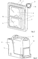
- Fig. 4 shows a possible embodiment of the housing 4 and the adapter 13.
- the means 12 for connecting the housing 4 to the adapter 13 are formed by a lever 12, through which the housing 4 can be clamped in the adapter 13. Possibly the lever 12 can be supported by further fastening elements or locking members.
- the housing is provided with an externally mounted handle 16, through which the housing 4 can be easily inserted into the adapter 13 and removed therefrom.
- Such a configuration is particularly suitable for use of the device in an aircraft for receiving image data, since such devices must be removed frequently so that the hard disks 1 can be read out.
- Fig. 5 shows one too Fig. 1 alternative embodiment, which does not belong to the invention.
- Elements designated by the same reference numerals have the same function and, with the exception of the following deviations, have the same or identical design.
- the housing 4 formed pressure-tight.
- the support structure 2 in this case has an embodiment which completes a circulation of the housing 4 gaseous medium (for example, air) around the hard disk 1 allows. It is also provided that the other arranged in the housing 4 system elements, such as the controller 11 are cooled by the circulation of the sealed in the housing 4 gaseous medium. In the housing 4, a cooling element 5 is arranged, which is designed as a fan. Within the housing 4 is also analogous to Fig. 1 a textile covering 9 is provided which is intended to control the circulation of the gaseous medium in such a way that as far as possible all elements contained in the housing 4 - in particular the hard disk 1 - tend to flow or be cooled.
- gaseous medium for example, air
- the fan 5 is according to Fig. 5 arranged on the outside of the support structure 2 such that the fan 5 actively sucks the gaseous medium from the interior of the support structure 2, in which the hard disks 1 are arranged.
- the textile covering 9 diverts the gaseous medium sucked out of the interior of the support structure 2 and forms the fan 5 directed opposite region of the support structure 2.
- the gaseous medium for cooling the hard disks 1 can again flow into the interior of the support structure 2.
- a principally possible and advantageous flow path is in Fig. 5 represented by the arrows.
- the fan 5 the system components contained in the interior of the housing 4 (hard disk 1, controller 11, etc.) and the flow path of the gaseous medium are arranged such that the heat is introduced into the housing 4 as strongly as possible. From the housing 4, the heat is released to the environment, whereby cooling is achieved.
- the solution according to the invention is particularly suitable for pressure-insulated and vibration-damped mounting of storage media.
- a holder is advantageous, instead of the storage media are used in the inventive solution.
Landscapes
- Cooling Or The Like Of Electrical Apparatus (AREA)
- Vibration Prevention Devices (AREA)
- Packaging For Recording Disks (AREA)
Description
- Die Erfindung betrifft einen Flugdatenspeicher zur Aufnahme von Bilddaten in einem Flugzeug mit einer Vorrichtung zur Halterung wenigstens eines Speichermediums.
- Aus dem allgemeinen Stand der Technik ist eine Vorrichtung zur Anordnung eines Speichermediums, beispielsweise eines Massenspeichers in Form einer Festplatte, bekannt, bei der das Speichermedium in eine mit einem Gehäuse verbundene Halterung eingebracht wird. Stöße und Schwingungen stören dabei im allgemeinen das Speichermedium nicht, insofern sich der zum Lesen oder Beschreiben des Speichermediums vorgesehene Festplattenkopf in einer Parkposition befindet. Sobald der Festplattenkopf jedoch zum Lesen oder zum Schreiben eingesetzt wird, können Schwingungen bzw. Stöße zu einer Beschädigung bzw. zu einer Zerstörung des Speichermediums führen. Stöße und Schwingungen können verschiedene Ursachen haben und bei den unterschiedlichsten Anwendungen auftreten. Regelmäßig ist dabei mit derartigen Belastungen zu rechnen, wenn das Speichermedium in Land-, Wasser- oder Luftfahrzeugen eingesetzt wird, bei denen während einer Bewegung derselben auf das Speichermedium geschrieben oder Informationen von dem Speichermedium gelesen werden müssen.
- Die
US 6,320,744 B1 beschreibt ein Array-Modul, das ein Array von elektronischen Einheiten enthält und in einem Installationsrahmen montiert ist. Die elektronischen Einheiten können durch Schienen in einem hermetisch abgedichteten Arraygehäuse montiert werden und Blind-Mate-Steckverbinder können die Geräte an eine hintere Platte anschließen. Blind-Mate-Steckverbinder können auch die hintere Platte mit dem Installationsrahmen für den externen Anschluss verbinden. Eine Vielzahl von elastischen Halterungen sind an dem Einbaurahmen befestigt, um das Rahmen- und Speicher-Array-Modul vor einem externen Schock zu schützen. Ein Thermotransfermechanismus überträgt Wärmeenergie zwischen den elektronischen Einheiten und einem Bereich außerhalb des Installationsrahmens. Die elektronischen Einheiten können in hermetisch abgedichteten Kammern eingeschlossen sein, die seitliche Schienen zur starren Befestigung an der Einheit und einen elastischen Träger aufweisen, der die Seitenschienen mit mindestens einer der Abdeckungen der hermetisch abgedichteten Kammer verbindet. Thermische Schienen können durch eine Vielzahl von elastischen Wärmeleitern entweder an den Seitenschienen oder an einer der Abdeckungen fest montiert werden, und ein Befestigungselement befestigt die thermischen Schienen abnehmbar an einer anderen Seitenschiene oder einer der Abdeckungen, so dass die thermischen Schienen und elastischen Wärmeleiter für die Wärmeleitung zwischen den Seitenschienen und einer der Abdeckungen sorgen. - Die
WO 03/019035 A2 - Die
US 6,002,588 bezieht sich auf den Schutz und das thermische Management von Geräten und insbesondere auf ein Verfahren zur Stoß- und Vibrationsisolation für Komponenten, welche auch eine kontrollierte Temperatur benötigen. - In ANONYMOUS: "Disk File with Reduced or Eliminated Air Effects. February 1981.", IBM TECHNICAL DISCLOSURE BULLETIN, Bd. 23, Nr. 9, 1. Februar 1981 (1981-02-01), Seiten 4310-4311, New York, US, ist eine Festplatte mit reduzierten oder eliminierten Lufteffekten angegeben.
- Um auch bei derart rauen Umgebungsbedingungen Daten von dem Speichermedium lesen zu können oder auf dasselbe zu schreiben, sind entsprechend teure Spezialfestplatten bekannt, die zwar derartige Stöße und Schwingungen wenigstens teilweise tolerieren können, aber nur niedrige Datenübertragungsraten zulassen. Von Nachteil dabei ist, dass somit die auf dem Markt als Standardprodukte mit entsprechender Übertragungsrate vorhandenen einfachen und preiswerten Festplatten nicht eingesetzt werden können, wodurch die Kosten um ein Vielfaches höher sind.
- Derartige Spezialfestplatten werden insbesondere auch dann eingesetzt, wenn es sich bei dem Speichermedium um einen Flugdatenspeicher handelt, auf den während eines Bildfluges große Datenmengen einer digitalen Kamera abgelegt werden sollen. Bei diesen Daten kann es sich z.B. um Bilddaten, ergänzende Daten zu den Bildern, wie z.B. Missionsdaten, Systeminformationen oder allgemeine Informationen für Post Processing handeln. Das Speichermedium ist hierbei im allgemeinen als Massenspeicher zur "digital mapping camera" ausgelegt.
- Im Flugzeug wird jede Speichereinheit mechanisch befestigt und elektrisch mit allen notwendigen Kabeln verbunden. Elektrisch und mechanisch ist jeder Flugdatenspeicher eine eigenständige Einheit, die über einen Bilddatenanschluss mit einer digitalen Kamera verbunden ist. Weiterhin ist ein Kontrolldaten-Eingang, ein Kontrolldaten-Ausgang und ein Versorgungsspannungs-Eingang, ein Versorgungsspannungs-Ausgang sowie ein serieller Anschluss zur Konfiguration vorhanden.
- Der Flugdatenspeicher speichert die Bilddaten während des Flugs. Nach der Landung wird der Flugdatenspeicher entnommen und die Bilddaten auf erdgebundene Massenspeicher kopiert. Nach dem Kopiervorgang und einer anschließenden Formatierung ist der Flugdatenspeicher wieder frei für weitere Bildflüge.
- Von Nachteil bei einem Einsatz eines Speichermediums als Flugdatenspeicher ist dabei jedoch, dass mit zunehmender Höhe der das Speichermedium umgebende Druck absinkt und sich somit möglicherweise ein Druck einstellt, der unter dem zulässigen Druck liegt, der für ein korrektes Arbeiten des Speichermediums notwendig ist.
- Problematisch bei den bisher bekannten Vorrichtungen zur Halterung eines Speichermediums ist außerdem, dass die von der Festplatte ausgehende Wärmeentwicklung nicht zuverlässig abgeführt werden kann.
- Die im Bezug auf den Einsatz als Flugdatenspeicher beschriebenen Probleme treten nicht nur in diesem Bereich auf, sondern auch in anderen Bereichen, in denen das Speichermedium in einer rauen Umgebung eingesetzt wird. Hierbei seien z.B. Anwendungen im Militärbereich, im industriellen Umfeld oder bei Feldanwendungen genannt.
- Der vorliegenden Erfindung liegt daher die Aufgabe zugrunde, einen Flugdatenspeicher der eingangs erwähnten Art mit einer Vorrichtung zur Halterung mindestens eines Speichermediums zu schaffen, welcher die vorgenannten Nachteile des Standes der Technik löst, bei dem das Speichermedium insbesondere gegen Vibrationen und Stöße sowie Druckschwankungen und eine übermäßige Wärmeentwicklung geschützt ist.
- Diese Aufgabe wird erfindungsgemäß durch Anspruch 1 gelöst.
- Durch die erfindungsgemäße Anordnung des Speichermediums wird dieses gegen Vibrationen, Schwingungen und Stöße geschützt. Somit kann das Speichermedium als relativ einfache und kostengünstige Standardfestplatte ausgebildet sein. Eine spezielle und somit kostengünstige Spezialanfertigung der Festplatte bzw. des zum Schreiben und/oder Lesen eingesetzten Festplattenkopfes ist somit nicht notwendig. Dadurch, dass das Speichermedium über eine Tragstruktur schwingungsgedämpft ist, kann das Speichermedium in einfacher Weise ausgetauscht werden, ohne dass die gesamte Dämpfungseinrichtung demontiert werden muss. Die Dämpfungseinrichtung und die Tragstruktur können auch beim Wechsel des Speichermediums bzw. bei einem reparaturbedingten oder einem kapazitätsbedingten Austausch unverändert verbleiben. Vorteilhaft ist es dabei, wenn die Dämpfungseinrichtung dynamisch ausgelegt ist.
- In numerischen Berechnungen und Versuchen hat sich herausgestellt, dass sich eine Ausgestaltung der Dämpfungseinrichtung mit einer Mehrzahl von Schwingungsisolatoren, die vorzugsweise als am Markt erhältliche Drahtseil-Schwingungsdämpfer ausgebildet sind, in besonderer Weise zur Dämpfung bzw. zur Absorption der auftretenden Stöße und Vibrationen eignet.
- Dadurch, dass das Speichermedium erfindungsgemäß druckdicht zu einer Außenatmosphäre abgegrenzt ist, wird verhindert, dass bei jedem Wechsel der Höhe, beispielsweise bei einem Einsatz in einem Flugzeug, der Druck im Bereich des Speichermediums absinkt und sich somit möglicherweise ein Druck einstellt, der ein korrektes Arbeiten des Speichermediums nicht mehr zulässt.
- Zudem wird so verhindert, dass sich Feuchtigkeit in der Tragstruktur ansammeln könnte, die bei entsprechend niedrigen Temperaturen zu einer für den Betrieb der Speichermedien unzulässigen Erhöhung der relativen Feuchte führen könnte.
- Durch die erfindungsgemäße Lösung wird ebenfalls das bei einem Einsatz eines Speichermediums regelmäßig auftretende Problem der Kühlung bzw. der Abführung der durch den Einsatz des Speichermediums entstehenden Wärme, gelöst. Hierzu wird ein Kühlelement eingesetzt, das das Speichermedium, welches druckdicht zu einer Außenatmosphäre abgegrenzt ist, kühlt. Durch die zur Außenatmosphäre druckdichte Anordnung des Speichermediums ist eine Kühlung desselben besonders wichtig, da ansonsten eine Überhitzung und somit eine Beschädigung des Speichermediums nicht zuverlässig ausgeschlossen werden kann.
- Durch die Vorrichtung können auch mehrere Speichermedien aufgenommen werden. Hierzu können beispielsweise mehrere Festplattenlaufwerke mechanisch und elektrisch zu einer leicht wechselbaren Einheit zusammengefasst und in einer Tragstruktur angeordnet werden. Alternativ ist es auch möglich, innerhalb eines Gehäuses mehrere Tragstrukturen anzuordnen.
- Von Vorteil ist es, wenn die Tragstruktur ebenfalls zur Aufnahme von elektrischen Systembestandteilen, wie Netzteil, Interfaces, Controller bzw. Raid-Controller usw. verwendet wird. In Versuchen hat sich dabei herausgestellt, dass auch für diese elektronischen Systembestandteile eine vibrations- und stoßgeschützte Anordnung vorteilhaft ist.
- Die Vorrichtung eignet sich in besonderer Weise, wenn das Speichermedium als Bestandteil eines Flugdatenspeichers in einem Flugzeug zur Speicherung der Bilddaten bzw. weiterer Daten verwendet wird. Von Vorteil ist es, wenn das Gehäuse innerhalb dessen die Tragstruktur mit dem Speichermedium angeordnet ist, mit Mitteln zur Befestigung an einem mit einem Flugzeug verbundenen Adapter ausgebildet ist.
- Eine Ausbildung des Gehäuses zur Befestigung an einem Adapter hat sich als besonders geeignet herausgestellt, um die Vorrichtung in einfacher Weise in verschiedenen Flugzeugtypen einsetzen zu können. Der Adapter kann dabei fest mit dem Flugzeug verbunden werden, sodass die Vorrichtung bzw. das Gehäuse eine entsprechende Führung erhält. Eine stoßsichere bzw. vibrationsgeschützte Anordnung des Gehäuses ist dabei nicht notwendig, da die auftretenden Stöße und Schwingungen durch die Dämpfungseinrichtung zwischen der Tragstruktur und dem Gehäuse absorbiert werden. Von Vorteil ist es dabei, wenn das Gehäuse Kupplungselemente aufweist, die zur Übertragung und/oder zum Empfang von Signalen und/oder einer Versorgungsspannung mit Kupplungselementen des Adapters verbindbar sind.
- Somit entsteht eine besonders einfache und vorteilhafte elektrische Kontaktierung des Speichermediums bzw. weiterer innerhalb des Gehäuses befindlicher Systembausteine mit einer Kabelverbindung, die beispielsweise zu einer Digitalkamera oder zum Bordnetz führt. Vorteilhaft ist es dabei, wenn durch die mechanische Fixierung des Gehäuses in dem Adapter gleichzeitig die elektrische Kontaktierung mit den angesprochenen Kabelverbindungen erfolgt. Von Vorteil ist es außerdem, dass durch die Dämpfungseinrichtung auch Stöße kompensiert bzw. absorbiert werden, die aus dem Einbringen des Gehäuses in den Adapter resultieren.
- In numerischen Berechnungen und Versuchen hat es sich als besonders geeignet herausgestellt, die Tragstruktur, in der das Speichermedium angeordnet ist, druckdicht auszubilden.
- Dies kann beispielsweise dadurch realisiert werden, dass die Tragstruktur als druckfestes bzw. druckdichtes Gehäuse ausgebildet ist. Das Speichermedium wird somit in einfacher Weise druckdicht abgekapselt und ist somit unabhängig gegen Druckschwankungen, die beispielsweise auftreten, wenn ein Flugzeug die Höhe wechselt.
- In einer Ausgestaltung der Erfindung kann dabei vorgesehen sein, dass die Tragstruktur Mittel aufweist, die ein definiertes Öffnen desselben ermöglichen, um (wenn die Außenatmosphäre ein höheres Druckniveau aufweist als der Innenraum der Tragstruktur) Luft in die Tragstruktur strömen zu lassen, da prinzipiell trotz einer druckdichten Ausbildung der Tragstruktur ein gewisser Druckverlust zwischen der Tragstruktur und der Außenatmosphäre nicht ausgeschlossen werden kann. Erfahrungsgemäß strömt bei einem Einsatz in großen Höhen mehr Luft pro Zeiteinheit aus der Tragstruktur als in der Phase am Boden zurückströmt, weil die Druckdifferenzen unterschiedlich sind. Einem zu niedrigen Innendruck kann dabei durch ein definiertes Öffnen der Tragstruktur entgegengewirkt werden.
- Um zu vermeiden, dass Feuchtigkeit, die beim Gasaustausch von außen nach innen transportiert werden kann, das Speichermedium beeinträchtigt, können aus dem allgemeinen Stand der Technik bekannte Trockenpatronen eingesetzt werden.
- In einer druckdichten Ausgestaltung der Tragstruktur kann vorgesehen sein, dass der Controller an der Außenseite der Tragstruktur angeordnet ist.
- Prinzipiell können der Controller sowie weitere Systembestandteile auch innerhalb der druckdichten Tragstruktur angeordnet sein. Dies ist jedoch nur für derartige Systembestandteile sinnvoll, die eine Druckstabilität brauchen bzw. für die sich diese in nennenswerter Weise vorteilhaft auswirkt.
- Von Vorteil ist es, wenn die Außenseite der Tragstruktur mit Kühlrippen versehen ist.
- In Versuchen hat sich herausgestellt, dass sich durch eine Ausgestaltung der Tragstruktur mit Kühlrippen eine besonders vorteilhafte Abführung der Wärme von der Tragstruktur an die Außenatmosphäre ergibt.
- Von Vorteil ist es, wenn das Kühlelement derart angeordnet bzw. eingesetzt wird, dass das Kühlelement hauptsächlich zur Kühlung der Außenseite der Tragstruktur und/oder des Controllers bzw. weiterer Systembestandteile dient. Vorgesehen sein kann dabei, dass das Kühlelement als Lüfter ausgebildet ist, der Luft von außerhalb des Gehäuses in das Gehäuse einbringt bzw. ansaugt. Das Gehäuse kann dabei zur Konvektion mit der Außenatmosphäre Luftdurchgangsöffnungen aufweisen. Als vorteilhaft hat sich dabei auch der Einsatz von Luftleitblechen herausgestellt, die die Tragstruktur bzw. den Controller und/oder weitere Systembestandteile umgeben und die den von dem Lüfter erzeugten Luftstrom gezielt an diesen vorbeiströmen lassen.
- Zur Steuerung des Luftstromes hat es sich außerdem als vorteilhaft herausgestellt, wenn zwischen dem Lüfter und der Tragstruktur bzw. dem Controller und/oder weiteren Systembestandteilen eine Bespannung vorgesehen ist. Die Bespannung kann dabei beispielsweise als Textilbespannung ausgebildet sein und verhindert, dass der Lüfter den Luftstrom in Bereiche fördert, er nicht wirksam ist. Durch die Bespannung lässt sich der Luftstrom gezielt zu den Bereichen leiten, an denen eine Wärmeabfuhr notwendig ist.
- In einer konstruktiven Ausgestaltung der Erfindung kann alternativ zu der druckdichten Ausgestaltung der Tragstruktur auch vorgesehen sein, dass das Gehäuse druckdicht ausgebildet ist. Die Tragstruktur kann dabei derart ausgebildet sein, dass eine Zirkulation des im Gehäuse abgeschlossenen gasförmigen Mediums (z.B. Luft) um das Speichermedium möglich ist. Hierbei handelt es sich um eine Ausführungsform, die für bestimmte Anwendungen vorteilhaft erscheinen mag.
- Generell hat sich in Versuchen jedoch herausgestellt, dass sich eine druckdichte Ausbildung der Tragstruktur, die hinsichtlich ihres Innenraums möglichst an das aufzunehmende Speichermedium angepasst ist, besonders eignet. Nachteilhaft bei der druckdichten Ausgestaltung des Gehäuses ist, dass keine kühle Außenluft zur direkten Kühlung der wärmeerzeugenden Elemente herangezogen werden kann. Die Kühlung der in dem druckdichten Gehäuse enthaltene Systembestandteil kann lediglich rein passiv erfolgen, indem diese die Wärme an das druckdichte Gehäuse abgeben und die Wärme von dem druckdichten Gehäuse anschließend an die Außenumgebung abgeleitet wird. Die Kühlung kann dabei verbessert werden, wenn innerhalb des druckdichten Gehäuses ein Kühlelement, beispielsweise ausgebildet als Lüfter, angeordnet ist. Das Kühlelement kann dabei zur Zirkulation des gasförmigen Mediums innerhalb des druckfesten Gehäuses verwendet werden, wodurch die Wärmeableitung in das Gehäuse verbessert wird. Zur Steuerung der Zirkulation des gasförmigen Mediums kann dabei eine Bespannung, vorzugsweise eine textile Bespannung eingesetzt werden, sodass innerhalb des druckdichten Gehäuses im wesentlichen die wärmeerzeugenden Systembestandteile, vorzugsweise das Speichermedium, durch den Lüfter gekühlt werden.
- Vorteilhafte Ausgestaltungen und Weiterbildungen der Erfindung ergeben sich aus den weiteren Unteransprüchen.
- Nachfolgend sind anhand der Zeichnung Ausführungsbeispiele der Erfindung prinzipmäßig dargestellt.
- Es zeigt:
- Fig. 1
- eine prinzipmäßige Darstellung einer Vorrichtung mit einem Speicherelement, das innerhalb einer druckdicht ausgebildeten Tragstruktur angeordnet ist;
- Fig. 2
- eine perspektivische Darstellung der Tragstruktur mit einem an der Außenseite befestigten Controller, Luftleitbleichen und einer Dämpfungseinrichtung zur Befestigung an einem nicht dargestellten Gehäuse;
- Fig. 3
- eine Innenansicht der Tragstruktur mit zwei als Festplatten ausgebildeten Speichermedien;
- Fig. 4
- eine perspektivische Darstellung eines Adapters in welchem ein Gehäuse der erfindungsgemäßen Vorrichtung eingesetzt ist, und
- Fig. 5
- eine zu
Fig. 1 alternative Ausgestaltung, welche nicht Teil der Erfindung ist, wobei das Gehäuse druckdicht ausgebildet ist. -
Fig. 1 zeigt die Vorrichtung zur Halterung wenigstens eines Speichermediums 1. Im Ausführungsbeispiel ist dabei vorgesehen, dass das Speichermedium 1 als Festplattenspeicher ausgebildet ist. Der Festplattenspeicher dient dabei dazu, die während des Bildfluges von einer digitalen Kamera erfassten Daten abzulegen. Digitale Kameras zur Aufnahme derartiger Daten sind aus dem allgemeinen Stand der Technik hinlänglich bekannt, weshalb im Ausführungsbeispiel hierauf nicht näher eingegangen wird. Prinzipiell eignet sich die Vorrichtung zum Einsatz in den unterschiedlichsten Gebieten, bei denen ein zuverlässiges Schreiben bzw. Lesen von Daten auf bzw. von einem Speichermedium erforderlich ist. Besonders bevorzugt eignet sich die Vorrichtung dabei in den Bereichen der Technik bei dem das Speichermedium während dem Lesen oder Schreiben Stößen, Vibrationen oder Schwingungen und/oder Druckschwankungen ausgesetzt ist. - Das Ausführungsbeispiel zeigt den Anwendungsfall eines Flugdatenspeichers, der zur Aufnahme von Bilddaten in einem Flugzeug eingesetzt wird.
- Da ein Teil der im Ausführungsbeispiel enthaltenen Elemente aus dem allgemeinen Stand der Technik bereits hinlänglich bekannt ist, wird nachfolgend lediglich auf die für die Erfindung wesentlichen Merkmale näher eingegangen.
- Im Ausführungsbeispiel ist das Speichermedium als handelsübliche Festplatte 1 ausgebildet.
- Wie aus
Fig. 1 ersichtlich ist, ist die Festplatte 1 in einer Tragstruktur 2 angeordnet, welche über eine Dämpfungseinrichtung 3 schwingungsgedämpft mit einem die Tragstruktur 2 umgebenden Gehäuse 4 verbunden ist. Die Festplatte 1 ist dabei druckdicht zu einer nicht näher dargestellten Außenatmosphäre abgegrenzt. Zur Kühlung der Festplatte ist ein Kühlelement 5 vorgesehen. Die druckdichte bzw. druckisolierte Anordnung der Festplatte 1 wird gemäßFig. 1 dadurch realisiert, dass die Tragstruktur 2 druckdicht ausgebildet ist. Die Tragstruktur 2 weist dabei einen Innenraum auf, der im wesentlichen den Abmessungen der Festplatte 1 entspricht. Vorgesehen ist dabei, dass zwischen der Innenseite der Tragstruktur 2 und der Festplatte 1 Wärmeleitelemente 6 angeordnet sind. GemäßFig. 1 sind die Wärmeleitelemente dabei als Leitmatten 6 ausgebildet. Die beim Betrieb der Festplatte 1 entstehende Temperatur wird somit über die Leitmatten 6 schnell und zuverlässig abtransportiert und in die Tragstruktur 2 eingeleitet. Von der Tragstruktur 2 strahlt die aufgenommene Wärme nach außen ab. Um einen schnellen Wärmeabtransport von der Oberfläche der Tragstruktur 2 zu unterstützen, weist die Tragstruktur 2 an ihrer Außenseite Kühlrippen 7 auf, die die Oberfläche entsprechend vergrößern. - In
Fig. 1 ist das Kühlelement 5 im wesentlichen zur Kühlung der Außenseite der Tragstruktur 2 vorgesehen. Das Kühlelement ist dabei als Lüfter 5 ausgebildet, der an dem Gehäuse 4 befestigt ist. Der Lüfter 5 bezieht seine zur Lüftung notwendige Luft von der Außenatmosphäre außerhalb des Gehäuses 4. Von dem Lüfter 5 wird die angezogene Luft in Richtung auf die Tragstruktur 2 gefördert bzw. ventiliert, sodass die Luft an einer möglichst großen Oberfläche der Tragstruktur 2 vorbeiströmt. Zur Konvektion mit der Außenatmosphäre weist das Gehäuse 4 zusätzlich zu der Ansaugöffnung für den Lüfter 5 Luftdurchgangsöffnungen 8 auf. Zur Steuerung des Luftstromes zwischen dem Lüfter 5 und der Tragstruktur 2 ist eine textile Bespannung 9 vorgesehen. Die textile Bespannung 9 ist dabei derart aufgespannt, dass die Tragstruktur 2 inmitten des von dem Lüfter 5 erzeugten Luftstromes liegt. Ergänzend zu der textilen Bespannung 9 weist das inFig. 1 dargestellte Ausführungsbeispiel Leitbleche 10 auf, die den vom Lüfter 5 erzeugten Luftstrom 2 ebenfalls entsprechend kanalisiert an der Tragstruktur 2 vorbeiführen sollen. Dabei ist gemäßFig. 1 vorgesehen, dass die textile Bespannung 9 zwischen dem Lüfter 5 und den Leitblechen 10 aufgespannt ist. - Die Leitbleche 10 können an den Kühlrippen 7 der Tragstruktur 2 anliegen bzw. an diese angrenzen, sodass durch die Leitbleche 10 und die Kühlrippen 7 Kanäle geschaffen werden, durch die die vom Lüfter 5 erzeugte Luft zur Kühlung der Außenseite der Tragstruktur 2 strömen kann.
- Wie aus
Fig. 1 ersichtlich ist, ist an der Außenseite des Tragstruktur 2 ein Controller 11 angeordnet. Zusätzlich zu dem Controller 11 können in nicht näher dargestellter Weise auch weitere Systembestandteile an der Außenseite der Tragstruktur 2 angeordnet sein. Die Systembestandteile können auch im druckdichten Innenraum der Tragstruktur 2 angeordnet sein, wenn dieses für deren Funktionsfähigkeit als vorteilhaft erscheint. - Wie sich aus
Fig. 1 des weiteren ergibt ist der Lüfter 5 derart ausgerichtet, dass zusätzlich zu der Außenseite der Tragstruktur 2 auch der Controller 11 gekühlt wird. Der Controller 11 ist somit innerhalb eines von den Leitblechen 10 begrenzten großen Luftkanales angeordnet. Ein möglicher Weg des Luftstromes ist inFig. 1 prinzipmäßig dargestellt. - Wie aus
Fig. 1 undFig. 5 ersichtlich ist, weist die Dämpfungseinrichtung 3 eine Mehrzahl an Schwingungsisolatoren 3a auf. In dem dargestellten Ausführungsbeispiel sind die Schwingungsisolatoren dabei als am Markt erhältliche Drahtseil-Schwingungsdämpfer 3a ausgebildet. Diese Drahtseil-Schwingungsdämpfer 3a sind dabei derart angeordnet, dass die Festplatte 1 bzw. die Tragstruktur 2 innerhalb des Gehäuses 4 aufgehängt ist. - Wie aus
Fig. 1 des weiteren ersichtlich ist, weist das Gehäuse 4 Mittel 12 zur Befestigung an einem mit einem Flugzeug verbundenen Adapter 13 auf. In nicht näher dargestellter Weise ist dabei auch vorgesehen, dass das Gehäuse 4 Kupplungselemente aufweist, die zur Übertragung/zum Empfang von Signalen und/oder einer Versorgungsspannung mit Kupplungselementen des Adapters 13 verbindbar sind. - Gemäß
Fig. 1 ist vorgesehen, dass der Lüfter 5 einen Luftfilter 14 zur Reinigung der angesaugten Luft aufweist. -
Fig. 2 zeigt eine Darstellung der Tragstruktur 2 an deren Außenseite acht Drahtseil-Schwingungsdämpfer 3a zur schwingungs- bzw. vibrationsgedämpften Verbindung mit einem inFig. 2 nicht dargestellten Gehäuse 4 vorgesehen sind. An einer Außenseite der Tragstruktur 2 ist dabei der Controller 11 angeordnet. Wie bereits gemäßFig. 1 prinzipmäßig dargestellt, weist die Tragstruktur 2 Kühlrippen 7 auf. Die Tragstruktur 2 sowie der Controller 11 werden von zwei Leitblechen 10 umfasst, sodass in Kombination mit den Kühlrippen 7 entsprechende Kühlkanäle geschaffen werden, durch die die von dem Lüfter 5 geförderte Luft (inFig. 2 nicht dargestellt) strömen kann. -
Fig. 3 zeigt eine Ansicht der Tragstruktur 2 gemäßFig. 2 , wobei eine Hälfte der Tragstruktur 2 entfernt wurde, sodass der Innenraum der Tragstruktur 2 prinzipmäßig dargestellt ist. Gemäß dem inFig. 3 dargestellten Ausführungsbeispiel sind dabei in dem Innenraum des Tragstruktur 2 zwei Festplatten 1 angeordnet. Die Festplatten 1 sind dabei derart angeordnet, dass eine möglichst große Fläche der Festplatten 1 der mit den Kühlrippen 7 versehenen Außenseite der Tragstruktur 2 zugewandt ist. Zwischen den Festplatten 1 und der Innenseite der Tragstruktur 2 sind die bereits erwähnten Wärmeleitelemente 6 in Form von Leitmatten angeordnet. - Die Tragstruktur 2 ist im wesentlichen aus zwei Hälften gebildet, die durch eine Mehrzahl von Schrauben miteinander verbunden werden können. Die beiden Hälften der Tragstruktur 2 sind dabei im wesentlichen als Halbschalen ausgebildet. Zwischen den beiden Halbschalen der Tragstruktur 2 ist die Anordnung einer Dichtung 15 vorzusehen. Somit wird eine ausreichend druckdichte Tragstruktur 2 gebildet, in der die beiden Festplatten 1 angeordnet werden können.
-
Fig. 4 zeigt eine mögliche Ausgestaltung des Gehäuses 4 und des Adapters 13. GemäßFig. 4 sind die Mittel 12 zur Verbindung des Gehäuses 4 mit dem Adapter 13 durch einen Hebel 12 ausgebildet, durch den das Gehäuse 4 in den Adapter 13 eingespannt werden kann. Gegebenenfalls kann der Hebel 12 dabei durch weitere Befestigungselemente bzw. Arretierungsglieder unterstützt werden. Das Gehäuse ist mit einem außenseitig angebrachten Griff 16 versehen, durch den das Gehäuse 4 in einfacher Weise in den Adapter 13 eingesetzt und wieder aus diesem entfernt werden kann. Eine derartige Ausgestaltung eignet sich in besonderer Weise für einen Einsatz der Vorrichtung in einem Flugzeug zur Aufnahme von Bilddaten, da derartige Vorrichtungen häufig entnommen werden müssen, damit die Festplatten 1 ausgelesen werden können. -
Fig. 5 zeigt eine zuFig. 1 alternative Ausgestaltung, welche nicht zur Erfindung gehört. Die inFig. 5 undFig. 1 mit gleichen Bezugszeichen bezeichneten Elemente haben dieselbe Funktion und sind mit Ausnahme der nachfolgenden Abweichungen analog bzw. identisch ausgebildet. Im Unterschied zuFig. 1 ist gemäßFig. 5 das Gehäuse 4 druckdicht ausgebildet. - Die Tragstruktur 2 weist dabei eine Ausgestaltung auf, die eine Zirkulation des im Gehäuse 4 abgeschlossen gasförmigen Mediums (beispielsweise Luft) um die Festplatte 1 ermöglicht. Dabei ist ebenfalls vorgesehen, dass die weiteren in dem Gehäuse 4 angeordneten Systemelemente, beispielsweise der Controller 11 durch die Zirkulation des im Gehäuse 4 abgeschlossenen gasförmigen Mediums gekühlt werden. In dem Gehäuse 4 ist ein Kühlelement 5 angeordnet, das als Lüfter ausgebildet ist. Innerhalb des Gehäuses 4 ist ebenfalls analog zu
Fig. 1 eine textile Bespannung 9 vorgesehen, die die Zirkulation des gasförmigen Mediums derart steuern soll, dass möglichst alle in dem Gehäuse 4 enthaltene Elemente - insbesondere die Festplatte 1 - die zu einer Wärmeentwicklung neigen umströmt bzw. gekühlt werden. - Der Lüfter 5 ist gemäß
Fig. 5 an der Außenseite der Tragstruktur 2 derart angeordnet, dass der Lüfter 5 das gasförmige Medium aktiv aus dem Innenraum der Tragstruktur 2, in welchem die Festplatten 1 angeordnet sind, saugt. Durch die textile Bespannung 9 wird das aus dem Innenraum der Tragstruktur 2 gesaugte gasförmige Medium umgeleitet und zu einem dem Lüfter 5 gegenüberliegenden Bereich der Tragstruktur 2 geleitet. Durch entsprechende Öffnungen der Tragstruktur 2 bzw. einem offenen Aufbau desselben kann das gasförmige Medium zur Kühlung der Festplatten 1 wieder in den Innenraum der Tragstruktur 2 einströmen. Ein prinzipiell möglicher und vorteilhafter Strömungsweg ist inFig. 5 durch die Pfeile dargestellt. Durch die Bespannung 9 und den Lüfter 5 wird eine konstante Strömung des gasförmigen Mediums durch den Innenraum der Tragstruktur 2 und somit entlang der Festplatten 1 realisiert. Der Lüfter 5, die im Innenraum des Gehäuses 4 enthaltenen Systembausteine (Festplatte 1, Controller 11 etc.) sowie der Strömungsweg des gasförmigen Mediums sind derart angeordnet, dass die Wärme möglichst stark in das Gehäuse 4 eingeleitet wird. Von dem Gehäuse 4 wird die Wärme an die Umgebung abgegeben, wodurch eine Kühlung erzielt wird. - Die erfindungsgemäße Lösung eignet sich in besonderer Weise zum druckisolierten und vibrationsgedämpften Befestigen von Speichermedien. In einer Weiterbildung können jedoch auch andere Systemelemente bei denen eine derartige Halterung vorteilhaft ist, anstelle der Speichermedien in die erfindungsgemäße Lösung eingesetzt werden.
Claims (11)
- Flugdatenspeicher zur Aufnahme von Bilddaten in einem Flugzeug mit einer Vorrichtung zur Halterung wenigstens eines Speichermediums (1), wobei das Speichermedium (1) in einer druckdicht ausgebildeten Tragstruktur (2) angeordnet ist, welche in einem die Tragstruktur (2) umgebenden Gehäuse (4) angeordnet ist, wobei ein Kühlelement (5) zur Kühlung des Speichermediums (1) und eines Controllers (11) vorgesehen ist, und wobei der Controller (11) an der Außenseite der Tragstruktur (2) angeordnet ist und die Tragstruktur (2) über Drahtseil-Schwingungsdämpfer (3a) schwingungsgedämpft innerhalb des Gehäuses (4) aufgehängt ist, wobei das Speichermedium (1) aus der Tragstruktur (2) ohne Demontage der aus den Drahtseil-Schwingungsdämpfern (3a) gebildeten Dämpfungseinrichtung (3) entnehmbar ist.
- Flugdatenspeicher nach Anspruch 1,
dadurch gekennzeichnet, dass das Gehäuse (4) mit Mitteln (12) zur Befestigung an einem mit einem Flugzeug verbundenen Adapter (13) ausgebildet ist. - Flugdatenspeicher nach Anspruch 2,
dadurch gekennzeichnet, dass das Gehäuse (4) Kupplungselemente aufweist, die zur Übertragung/zum Empfang von Signalen und/oder einer Versorgungsspannung mit Kupplungselementen des Adapters (13) verbindbar sind. - Flugdatenspeicher nach Anspruch 1, 2 oder 3,
dadurch gekennzeichnet, dass zwischen der Innenseite der Tragstruktur (2) und dem Speichermedium (1) Wärmeleitelemente (6) angeordnet sind. - Flugdatenspeicher nach Anspruch 4,
dadurch gekennzeichnet, dass die Wärmeleitelemente als Leitmatten (6) ausgebildet sind. - Flugdatenspeicher nach einem der Ansprüche 1 bis 5,
dadurch gekennzeichnet, dass die Außenseite der Tragstruktur (2) mit Kühlrippen (7) versehen ist. - Flugdatenspeicher nach einem der Ansprüche 1 bis 6,
dadurch gekennzeichnet, dass das Kühlelement (5) zur Kühlung der Außenseite der Tragstruktur (2) und des Controllers bzw. weiterer Systembestandteile dient. - Flugdatenspeicher nach einem der Ansprüche 1 bis 7,
dadurch gekennzeichnet, dass das Gehäuse (4) zur Konvektion mit der Außenatmosphäre Luftdurchgangsöffnungen (8) aufweist. - Flugdatenspeicher nach einem der Ansprüche 1 bis 8,
dadurch gekennzeichnet, dass das Kühlelement als Lüfter (5) ausgebildet ist, der Luft von außerhalb des Gehäuses in das Gehäuse (4) einbringt. - Flugdatenspeicher nach Anspruch 9,
dadurch gekennzeichnet, dass zur Steuerung des Luftstroms zwischen dem Lüfter (5) und der Tragstruktur (2) eine Bespannung (9) vorgesehen ist. - Flugdatenspeicher nach einem der Ansprüche 1 bis 10,
dadurch gekennzeichnet, dass der von der Tragstruktur (2) ausgebildete Innenraum im Wesentlichen an die Form des Speichermediums (1) angepasst ist.
Applications Claiming Priority (2)
| Application Number | Priority Date | Filing Date | Title |
|---|---|---|---|
| DE102004013876A DE102004013876A1 (de) | 2004-03-20 | 2004-03-20 | Vorrichtung zur Halterung eines Speichermediums |
| DE102004013876 | 2004-03-20 |
Publications (3)
| Publication Number | Publication Date |
|---|---|
| EP1577895A2 EP1577895A2 (de) | 2005-09-21 |
| EP1577895A3 EP1577895A3 (de) | 2008-01-23 |
| EP1577895B1 true EP1577895B1 (de) | 2017-09-20 |
Family
ID=34833227
Family Applications (1)
| Application Number | Title | Priority Date | Filing Date |
|---|---|---|---|
| EP05002637.6A Expired - Lifetime EP1577895B1 (de) | 2004-03-20 | 2005-02-09 | Vorrichtung zur Halterung eines Speichermediums |
Country Status (5)
| Country | Link |
|---|---|
| US (1) | US7353527B2 (de) |
| EP (1) | EP1577895B1 (de) |
| JP (1) | JP5041670B2 (de) |
| DE (1) | DE102004013876A1 (de) |
| ES (1) | ES2650991T3 (de) |
Families Citing this family (13)
| Publication number | Priority date | Publication date | Assignee | Title |
|---|---|---|---|---|
| US7752775B2 (en) | 2000-03-10 | 2010-07-13 | Lyden Robert M | Footwear with removable lasting board and cleats |
| DE102004011680B4 (de) | 2004-03-10 | 2007-08-23 | Adidas International Marketing B.V. | Stollenschuh |
| DE102004013875A1 (de) * | 2004-03-20 | 2005-11-17 | Z/I Imaging Ltd., Shannon | Vorrichtung zur Befestigung einer portablen elektronischen Einheit |
| CN101023490A (zh) * | 2004-09-17 | 2007-08-22 | 齐拉泰克斯技术有限公司 | 磁盘驱动器装置及机架 |
| WO2007076565A1 (en) * | 2006-01-03 | 2007-07-12 | Continuum Audio Labs Pty Ltd | Vibration isolation assembly |
| JP2008262628A (ja) * | 2007-04-11 | 2008-10-30 | Hiroshi Miyoshi | ハードディスク等情報記録装置の騒音を遮断する収容箱 |
| DE102008018094A1 (de) | 2008-04-09 | 2009-10-15 | Kolt Engineering Gmbh | Dämpfungsanordnung |
| US20100051778A1 (en) * | 2008-09-03 | 2010-03-04 | Albert Taan Wu | Controlled Space with Anti-Shock Function for Automotive Electronics |
| US8934194B2 (en) * | 2011-01-09 | 2015-01-13 | Erhard Schreck | System and method for maintaining a low density gas environment in a disk drive |
| JP2015195069A (ja) | 2014-03-31 | 2015-11-05 | 富士通株式会社 | ストレージ装置、ストレージ装置の製造方法及びその測定方法 |
| CN108869631A (zh) * | 2018-09-18 | 2018-11-23 | 郑州讯轨通信科技有限公司 | 一种减震型物联网通信机箱 |
| CN112268399B (zh) * | 2020-09-24 | 2022-02-01 | 康帅冷链设备科技江苏有限公司 | 一种冷库热处理冷风机组 |
| CN112576684B (zh) * | 2020-11-27 | 2022-07-12 | 王文举 | 一种中央空调专用的具有减震防震功能的装置 |
Citations (3)
| Publication number | Priority date | Publication date | Assignee | Title |
|---|---|---|---|---|
| DE29610411U1 (de) * | 1996-06-13 | 1996-08-14 | Siemens AG, 80333 München | Elektronisches Gerät mit Massenspeicher |
| US6002588A (en) * | 1997-12-04 | 1999-12-14 | Lockheed Martin Corporation | Thermally conductive vibration isolators |
| WO2003019035A2 (en) * | 2001-08-08 | 2003-03-06 | Isic A/S | Vibration damper for dampening vibrations at low frequencies |
Family Cites Families (17)
| Publication number | Priority date | Publication date | Assignee | Title |
|---|---|---|---|---|
| US4831476A (en) * | 1985-07-15 | 1989-05-16 | Allen-Bradley Company | Disc drive isolation system |
| US4937806A (en) * | 1988-02-12 | 1990-06-26 | Mdb Systems, Inc. | Shock-isolated portable mass data storage device |
| JPH0739967Y2 (ja) * | 1989-11-22 | 1995-09-13 | 株式会社間組 | 石張り工用建設機械 |
| JP3716453B2 (ja) * | 1995-05-31 | 2005-11-16 | ソニー株式会社 | ディスクプレーヤ装置 |
| JPH09153277A (ja) * | 1995-11-29 | 1997-06-10 | Hitachi Ltd | 情報記録再生装置 |
| JPH10320709A (ja) * | 1997-05-20 | 1998-12-04 | Sony Corp | 磁気テープ内蔵式記録再生装置 |
| JP3456131B2 (ja) * | 1997-12-02 | 2003-10-14 | 松下電器産業株式会社 | スピーカ |
| JP2000034682A (ja) * | 1998-07-13 | 2000-02-02 | Nec Eng Ltd | 被移動体駆動用ワイヤ |
| US6289678B1 (en) * | 1998-12-03 | 2001-09-18 | Phoenix Group, Inc. | Environmental system for rugged disk drive |
| EP1163570A4 (de) * | 1999-02-19 | 2007-12-19 | Gen Dynamics Inf Systems Inc | Gehäuse für datenspeicherung |
| US6560064B1 (en) * | 2000-03-21 | 2003-05-06 | International Business Machines Corporation | Disk array system with internal environmental controls |
| US6671124B2 (en) * | 2001-09-07 | 2003-12-30 | Lockheed Martin Corporation | Shock and vibration system |
| JP3922957B2 (ja) * | 2002-04-03 | 2007-05-30 | 松下電器産業株式会社 | 磁気記録再生装置カートリッジおよびそれを用いる情報処理装置 |
| US6862180B2 (en) * | 2002-05-24 | 2005-03-01 | Adc Dsl Systems, Inc. | Housings for circuit cards |
| JP2004014032A (ja) * | 2002-06-07 | 2004-01-15 | Toshiba Corp | 電子機器 |
| JP2004063029A (ja) * | 2002-07-30 | 2004-02-26 | Sony Corp | 情報記憶装置 |
| TWI245276B (en) * | 2004-09-17 | 2005-12-11 | Lite On It Corp | Shock-absorbing structure applied in optical storage/reading device |
-
2004
- 2004-03-20 DE DE102004013876A patent/DE102004013876A1/de not_active Ceased
-
2005
- 2005-02-09 EP EP05002637.6A patent/EP1577895B1/de not_active Expired - Lifetime
- 2005-02-09 ES ES05002637.6T patent/ES2650991T3/es not_active Expired - Lifetime
- 2005-03-18 US US11/084,558 patent/US7353527B2/en not_active Expired - Fee Related
- 2005-03-22 JP JP2005081665A patent/JP5041670B2/ja not_active Expired - Fee Related
Patent Citations (3)
| Publication number | Priority date | Publication date | Assignee | Title |
|---|---|---|---|---|
| DE29610411U1 (de) * | 1996-06-13 | 1996-08-14 | Siemens AG, 80333 München | Elektronisches Gerät mit Massenspeicher |
| US6002588A (en) * | 1997-12-04 | 1999-12-14 | Lockheed Martin Corporation | Thermally conductive vibration isolators |
| WO2003019035A2 (en) * | 2001-08-08 | 2003-03-06 | Isic A/S | Vibration damper for dampening vibrations at low frequencies |
Non-Patent Citations (2)
| Title |
|---|
| ALAIN QUEAU: "LARGE CAPACITY AIRBORNE DATA RECORDERS FOR RECONNAISSANCE APPLICATIONS", THIC INC., THE PREMIER ADVANCED RECORDING TECHNOLOGY FORUM, 12 October 1999 (1999-10-12), Virginia Beach, VA, USA, XP055357915, Retrieved from the Internet <URL:http://www.thic.org/pdf/Oct99/enertec.aqueau.991012.pdf> [retrieved on 20170323] * |
| ANONYMOUS: "Disk File with Reduced or Eliminated Air Effects. February 1981.", IBM TECHNICAL DISCLOSURE BULLETIN, vol. 23, no. 9, 1 February 1981 (1981-02-01), New York, US, pages 4310 - 4311 * |
Also Published As
| Publication number | Publication date |
|---|---|
| EP1577895A3 (de) | 2008-01-23 |
| EP1577895A2 (de) | 2005-09-21 |
| ES2650991T3 (es) | 2018-01-23 |
| DE102004013876A1 (de) | 2005-10-06 |
| US20050240950A1 (en) | 2005-10-27 |
| JP2005267842A (ja) | 2005-09-29 |
| US7353527B2 (en) | 2008-04-01 |
| JP5041670B2 (ja) | 2012-10-03 |
Similar Documents
| Publication | Publication Date | Title |
|---|---|---|
| EP1577895B1 (de) | Vorrichtung zur Halterung eines Speichermediums | |
| DE60317389T2 (de) | Abkühlungssystem für eng zusammengestellte Speichervorrichtungen | |
| DE69721139T2 (de) | Fehlertolerante Kühlung für ein Einschubgehäuse | |
| DE10296275T5 (de) | Speichervorrichtungsgestell mit entlüfteten Schienen | |
| DE112017000207B4 (de) | Akustische Dämpfung in Datenspeichergehäusen | |
| DE69624596T2 (de) | Gerät zur sprühkühlung von mehreren elektronischen modulen | |
| DE69820589T2 (de) | Dämpfungsvorrichtung für festplattenlaufwerk in einem tragbaren computer | |
| EP1579747B1 (de) | Messgerätmodule und messgerät | |
| EP1825727B1 (de) | Keilverriegelung für ein elektronisches schaltungskartenmodul | |
| US9485888B2 (en) | Cooling system for use in a mass storage chassis assembly | |
| DE102021203625A1 (de) | Elektronikbaugruppe eines Kraftfahrzeugs | |
| DE9116755U1 (de) | Chassis eines Gerätes | |
| DE102008050778A1 (de) | Kühlanordnung für einen Elektro- oder Geräteschrank mit Luft-Luft-Wärmetauscherkassetten | |
| DE102013218095A1 (de) | Elektronische Bewegtbildkamera | |
| EP1705976B1 (de) | Messgerätmodul | |
| WO2023160963A1 (de) | Vorrichtung mit austauschbaren elektronikbaugruppen eines kraftfahrzeugs | |
| DE102021203345B3 (de) | Fahrzeug mit einem DNA-Speicher | |
| DE202005004448U1 (de) | Gehäuse zur Aufnahme von elektronischen Steckbaugruppen | |
| DE10007458B4 (de) | Kopplungsanschluss für eine Speichervorrichtung | |
| EP1971196A2 (de) | Aufklappbares Gehäuse für elektronische Schaltungsanordnungen | |
| DE60312966T2 (de) | Lüftereinheit zur Wärmeabfuhr einer elektronischen Vorrichtung | |
| DE102022202018A1 (de) | Austauschbare Elektronikbaugruppe eines Kraftfahrzeugs | |
| CN214708227U (zh) | 一种模拟信号转脉冲信号的驱动装置 | |
| CN215527093U (zh) | 一种基于应急作战指挥的全场景复盘展示装置 | |
| EP4333162B1 (de) | Tragstruktur für eine anzahl an batteriemodulen und batteriemodulanordnung |
Legal Events
| Date | Code | Title | Description |
|---|---|---|---|
| PUAI | Public reference made under article 153(3) epc to a published international application that has entered the european phase |
Free format text: ORIGINAL CODE: 0009012 |
|
| AK | Designated contracting states |
Kind code of ref document: A2 Designated state(s): AT BE BG CH CY CZ DE DK EE ES FI FR GB GR HU IE IS IT LI LT LU MC NL PL PT RO SE SI SK TR |
|
| AX | Request for extension of the european patent |
Extension state: AL BA HR LV MK YU |
|
| RAP1 | Party data changed (applicant data changed or rights of an application transferred) |
Owner name: Z/I IMAGING LTD. |
|
| REG | Reference to a national code |
Ref country code: HK Ref legal event code: DE Ref document number: 1085564 Country of ref document: HK |
|
| PUAL | Search report despatched |
Free format text: ORIGINAL CODE: 0009013 |
|
| AK | Designated contracting states |
Kind code of ref document: A3 Designated state(s): AT BE BG CH CY CZ DE DK EE ES FI FR GB GR HU IE IS IT LI LT LU MC NL PL PT RO SE SI SK TR |
|
| AX | Request for extension of the european patent |
Extension state: AL BA HR LV MK YU |
|
| 17P | Request for examination filed |
Effective date: 20080312 |
|
| 17Q | First examination report despatched |
Effective date: 20080416 |
|
| AKX | Designation fees paid |
Designated state(s): AT BE BG CH CY CZ DE DK EE ES FI FR GB GR HU IE IS IT LI LT LU MC NL PL PT RO SE SI SK TR |
|
| RAP1 | Party data changed (applicant data changed or rights of an application transferred) |
Owner name: LEICA GEOSYSTEMS AG |
|
| REG | Reference to a national code |
Ref country code: DE Ref legal event code: R079 Ref document number: 502005015712 Country of ref document: DE Free format text: PREVIOUS MAIN CLASS: G11B0033080000 Ipc: G11B0033040000 |
|
| GRAP | Despatch of communication of intention to grant a patent |
Free format text: ORIGINAL CODE: EPIDOSNIGR1 |
|
| RIC1 | Information provided on ipc code assigned before grant |
Ipc: G11B 33/04 20060101AFI20170329BHEP |
|
| INTG | Intention to grant announced |
Effective date: 20170419 |
|
| GRAS | Grant fee paid |
Free format text: ORIGINAL CODE: EPIDOSNIGR3 |
|
| GRAA | (expected) grant |
Free format text: ORIGINAL CODE: 0009210 |
|
| AK | Designated contracting states |
Kind code of ref document: B1 Designated state(s): AT BE BG CH CY CZ DE DK EE ES FI FR GB GR HU IE IS IT LI LT LU MC NL PL PT RO SE SI SK TR |
|
| REG | Reference to a national code |
Ref country code: GB Ref legal event code: FG4D Free format text: NOT ENGLISH |
|
| REG | Reference to a national code |
Ref country code: CH Ref legal event code: EP |
|
| REG | Reference to a national code |
Ref country code: AT Ref legal event code: REF Ref document number: 930743 Country of ref document: AT Kind code of ref document: T Effective date: 20171015 |
|
| REG | Reference to a national code |
Ref country code: IE Ref legal event code: FG4D Free format text: LANGUAGE OF EP DOCUMENT: GERMAN |
|
| REG | Reference to a national code |
Ref country code: DE Ref legal event code: R096 Ref document number: 502005015712 Country of ref document: DE |
|
| REG | Reference to a national code |
Ref country code: CH Ref legal event code: NV Representative=s name: KAMINSKI HARMANN PATENTANWAELTE AG, LI |
|
| REG | Reference to a national code |
Ref country code: NL Ref legal event code: FP |
|
| REG | Reference to a national code |
Ref country code: SE Ref legal event code: TRGR |
|
| REG | Reference to a national code |
Ref country code: ES Ref legal event code: FG2A Ref document number: 2650991 Country of ref document: ES Kind code of ref document: T3 Effective date: 20180123 |
|
| PG25 | Lapsed in a contracting state [announced via postgrant information from national office to epo] |
Ref country code: LT Free format text: LAPSE BECAUSE OF FAILURE TO SUBMIT A TRANSLATION OF THE DESCRIPTION OR TO PAY THE FEE WITHIN THE PRESCRIBED TIME-LIMIT Effective date: 20170920 Ref country code: FI Free format text: LAPSE BECAUSE OF FAILURE TO SUBMIT A TRANSLATION OF THE DESCRIPTION OR TO PAY THE FEE WITHIN THE PRESCRIBED TIME-LIMIT Effective date: 20170920 |
|
| REG | Reference to a national code |
Ref country code: LT Ref legal event code: MG4D |
|
| REG | Reference to a national code |
Ref country code: FR Ref legal event code: PLFP Year of fee payment: 14 |
|
| PG25 | Lapsed in a contracting state [announced via postgrant information from national office to epo] |
Ref country code: GR Free format text: LAPSE BECAUSE OF FAILURE TO SUBMIT A TRANSLATION OF THE DESCRIPTION OR TO PAY THE FEE WITHIN THE PRESCRIBED TIME-LIMIT Effective date: 20171221 Ref country code: BG Free format text: LAPSE BECAUSE OF FAILURE TO SUBMIT A TRANSLATION OF THE DESCRIPTION OR TO PAY THE FEE WITHIN THE PRESCRIBED TIME-LIMIT Effective date: 20171220 |
|
| PG25 | Lapsed in a contracting state [announced via postgrant information from national office to epo] |
Ref country code: RO Free format text: LAPSE BECAUSE OF FAILURE TO SUBMIT A TRANSLATION OF THE DESCRIPTION OR TO PAY THE FEE WITHIN THE PRESCRIBED TIME-LIMIT Effective date: 20170920 Ref country code: PL Free format text: LAPSE BECAUSE OF FAILURE TO SUBMIT A TRANSLATION OF THE DESCRIPTION OR TO PAY THE FEE WITHIN THE PRESCRIBED TIME-LIMIT Effective date: 20170920 Ref country code: CZ Free format text: LAPSE BECAUSE OF FAILURE TO SUBMIT A TRANSLATION OF THE DESCRIPTION OR TO PAY THE FEE WITHIN THE PRESCRIBED TIME-LIMIT Effective date: 20170920 |
|
| PG25 | Lapsed in a contracting state [announced via postgrant information from national office to epo] |
Ref country code: SK Free format text: LAPSE BECAUSE OF FAILURE TO SUBMIT A TRANSLATION OF THE DESCRIPTION OR TO PAY THE FEE WITHIN THE PRESCRIBED TIME-LIMIT Effective date: 20170920 Ref country code: EE Free format text: LAPSE BECAUSE OF FAILURE TO SUBMIT A TRANSLATION OF THE DESCRIPTION OR TO PAY THE FEE WITHIN THE PRESCRIBED TIME-LIMIT Effective date: 20170920 Ref country code: IS Free format text: LAPSE BECAUSE OF FAILURE TO SUBMIT A TRANSLATION OF THE DESCRIPTION OR TO PAY THE FEE WITHIN THE PRESCRIBED TIME-LIMIT Effective date: 20180120 Ref country code: IT Free format text: LAPSE BECAUSE OF FAILURE TO SUBMIT A TRANSLATION OF THE DESCRIPTION OR TO PAY THE FEE WITHIN THE PRESCRIBED TIME-LIMIT Effective date: 20170920 |
|
| REG | Reference to a national code |
Ref country code: DE Ref legal event code: R097 Ref document number: 502005015712 Country of ref document: DE |
|
| PLBE | No opposition filed within time limit |
Free format text: ORIGINAL CODE: 0009261 |
|
| STAA | Information on the status of an ep patent application or granted ep patent |
Free format text: STATUS: NO OPPOSITION FILED WITHIN TIME LIMIT |
|
| PG25 | Lapsed in a contracting state [announced via postgrant information from national office to epo] |
Ref country code: DK Free format text: LAPSE BECAUSE OF FAILURE TO SUBMIT A TRANSLATION OF THE DESCRIPTION OR TO PAY THE FEE WITHIN THE PRESCRIBED TIME-LIMIT Effective date: 20170920 |
|
| 26N | No opposition filed |
Effective date: 20180621 |
|
| REG | Reference to a national code |
Ref country code: HK Ref legal event code: WD Ref document number: 1085564 Country of ref document: HK |
|
| PG25 | Lapsed in a contracting state [announced via postgrant information from national office to epo] |
Ref country code: MC Free format text: LAPSE BECAUSE OF FAILURE TO SUBMIT A TRANSLATION OF THE DESCRIPTION OR TO PAY THE FEE WITHIN THE PRESCRIBED TIME-LIMIT Effective date: 20170920 |
|
| REG | Reference to a national code |
Ref country code: IE Ref legal event code: MM4A |
|
| REG | Reference to a national code |
Ref country code: BE Ref legal event code: MM Effective date: 20180228 |
|
| PG25 | Lapsed in a contracting state [announced via postgrant information from national office to epo] |
Ref country code: LU Free format text: LAPSE BECAUSE OF NON-PAYMENT OF DUE FEES Effective date: 20180209 Ref country code: SI Free format text: LAPSE BECAUSE OF FAILURE TO SUBMIT A TRANSLATION OF THE DESCRIPTION OR TO PAY THE FEE WITHIN THE PRESCRIBED TIME-LIMIT Effective date: 20170920 |
|
| PG25 | Lapsed in a contracting state [announced via postgrant information from national office to epo] |
Ref country code: IE Free format text: LAPSE BECAUSE OF NON-PAYMENT OF DUE FEES Effective date: 20180209 |
|
| PG25 | Lapsed in a contracting state [announced via postgrant information from national office to epo] |
Ref country code: BE Free format text: LAPSE BECAUSE OF NON-PAYMENT OF DUE FEES Effective date: 20180228 |
|
| PGFP | Annual fee paid to national office [announced via postgrant information from national office to epo] |
Ref country code: NL Payment date: 20190226 Year of fee payment: 15 |
|
| PGFP | Annual fee paid to national office [announced via postgrant information from national office to epo] |
Ref country code: DE Payment date: 20190227 Year of fee payment: 15 Ref country code: CH Payment date: 20190304 Year of fee payment: 15 Ref country code: ES Payment date: 20190301 Year of fee payment: 15 Ref country code: GB Payment date: 20190227 Year of fee payment: 15 |
|
| PGFP | Annual fee paid to national office [announced via postgrant information from national office to epo] |
Ref country code: FR Payment date: 20190225 Year of fee payment: 15 Ref country code: AT Payment date: 20190122 Year of fee payment: 15 Ref country code: SE Payment date: 20190227 Year of fee payment: 15 |
|
| PG25 | Lapsed in a contracting state [announced via postgrant information from national office to epo] |
Ref country code: TR Free format text: LAPSE BECAUSE OF FAILURE TO SUBMIT A TRANSLATION OF THE DESCRIPTION OR TO PAY THE FEE WITHIN THE PRESCRIBED TIME-LIMIT Effective date: 20170920 |
|
| PG25 | Lapsed in a contracting state [announced via postgrant information from national office to epo] |
Ref country code: HU Free format text: LAPSE BECAUSE OF FAILURE TO SUBMIT A TRANSLATION OF THE DESCRIPTION OR TO PAY THE FEE WITHIN THE PRESCRIBED TIME-LIMIT; INVALID AB INITIO Effective date: 20050209 Ref country code: PT Free format text: LAPSE BECAUSE OF FAILURE TO SUBMIT A TRANSLATION OF THE DESCRIPTION OR TO PAY THE FEE WITHIN THE PRESCRIBED TIME-LIMIT Effective date: 20170920 |
|
| PG25 | Lapsed in a contracting state [announced via postgrant information from national office to epo] |
Ref country code: CY Free format text: LAPSE BECAUSE OF FAILURE TO SUBMIT A TRANSLATION OF THE DESCRIPTION OR TO PAY THE FEE WITHIN THE PRESCRIBED TIME-LIMIT Effective date: 20170920 |
|
| REG | Reference to a national code |
Ref country code: DE Ref legal event code: R119 Ref document number: 502005015712 Country of ref document: DE |
|
| REG | Reference to a national code |
Ref country code: SE Ref legal event code: EUG |
|
| REG | Reference to a national code |
Ref country code: CH Ref legal event code: PL |
|
| REG | Reference to a national code |
Ref country code: NL Ref legal event code: MM Effective date: 20200301 |
|
| REG | Reference to a national code |
Ref country code: AT Ref legal event code: MM01 Ref document number: 930743 Country of ref document: AT Kind code of ref document: T Effective date: 20200209 |
|
| GBPC | Gb: european patent ceased through non-payment of renewal fee |
Effective date: 20200209 |
|
| PG25 | Lapsed in a contracting state [announced via postgrant information from national office to epo] |
Ref country code: SE Free format text: LAPSE BECAUSE OF NON-PAYMENT OF DUE FEES Effective date: 20200210 |
|
| PG25 | Lapsed in a contracting state [announced via postgrant information from national office to epo] |
Ref country code: CH Free format text: LAPSE BECAUSE OF NON-PAYMENT OF DUE FEES Effective date: 20200229 Ref country code: LI Free format text: LAPSE BECAUSE OF NON-PAYMENT OF DUE FEES Effective date: 20200229 Ref country code: AT Free format text: LAPSE BECAUSE OF NON-PAYMENT OF DUE FEES Effective date: 20200209 |
|
| PG25 | Lapsed in a contracting state [announced via postgrant information from national office to epo] |
Ref country code: NL Free format text: LAPSE BECAUSE OF NON-PAYMENT OF DUE FEES Effective date: 20200301 |
|
| PG25 | Lapsed in a contracting state [announced via postgrant information from national office to epo] |
Ref country code: FR Free format text: LAPSE BECAUSE OF NON-PAYMENT OF DUE FEES Effective date: 20200229 Ref country code: GB Free format text: LAPSE BECAUSE OF NON-PAYMENT OF DUE FEES Effective date: 20200209 Ref country code: DE Free format text: LAPSE BECAUSE OF NON-PAYMENT OF DUE FEES Effective date: 20200901 |
|
| REG | Reference to a national code |
Ref country code: ES Ref legal event code: FD2A Effective date: 20210705 |
|
| PG25 | Lapsed in a contracting state [announced via postgrant information from national office to epo] |
Ref country code: ES Free format text: LAPSE BECAUSE OF NON-PAYMENT OF DUE FEES Effective date: 20200210 |