EP1577565A2 - Ventil, insbesondere Druckregelventil - Google Patents
Ventil, insbesondere Druckregelventil Download PDFInfo
- Publication number
- EP1577565A2 EP1577565A2 EP05002345A EP05002345A EP1577565A2 EP 1577565 A2 EP1577565 A2 EP 1577565A2 EP 05002345 A EP05002345 A EP 05002345A EP 05002345 A EP05002345 A EP 05002345A EP 1577565 A2 EP1577565 A2 EP 1577565A2
- Authority
- EP
- European Patent Office
- Prior art keywords
- valve
- throttle
- piston
- tank
- connection
- Prior art date
- Legal status (The legal status is an assumption and is not a legal conclusion. Google has not performed a legal analysis and makes no representation as to the accuracy of the status listed.)
- Granted
Links
- 238000013016 damping Methods 0.000 claims abstract description 46
- 239000012530 fluid Substances 0.000 claims description 25
- 230000002093 peripheral effect Effects 0.000 claims description 6
- 230000011664 signaling Effects 0.000 claims description 6
- 230000006835 compression Effects 0.000 claims description 5
- 238000007906 compression Methods 0.000 claims description 5
- 230000001105 regulatory effect Effects 0.000 abstract description 3
- 238000009434 installation Methods 0.000 description 6
- 238000007789 sealing Methods 0.000 description 3
- 230000001419 dependent effect Effects 0.000 description 2
- 238000006073 displacement reaction Methods 0.000 description 2
- 238000000034 method Methods 0.000 description 2
- 150000001875 compounds Chemical class 0.000 description 1
- 230000000694 effects Effects 0.000 description 1
- 230000002996 emotional effect Effects 0.000 description 1
- 238000007654 immersion Methods 0.000 description 1
- 238000004519 manufacturing process Methods 0.000 description 1
- 238000005457 optimization Methods 0.000 description 1
- 230000003094 perturbing effect Effects 0.000 description 1
- 239000010409 thin film Substances 0.000 description 1
- 230000001052 transient effect Effects 0.000 description 1
Images
Classifications
-
- F—MECHANICAL ENGINEERING; LIGHTING; HEATING; WEAPONS; BLASTING
- F15—FLUID-PRESSURE ACTUATORS; HYDRAULICS OR PNEUMATICS IN GENERAL
- F15B—SYSTEMS ACTING BY MEANS OF FLUIDS IN GENERAL; FLUID-PRESSURE ACTUATORS, e.g. SERVOMOTORS; DETAILS OF FLUID-PRESSURE SYSTEMS, NOT OTHERWISE PROVIDED FOR
- F15B13/00—Details of servomotor systems ; Valves for servomotor systems
- F15B13/02—Fluid distribution or supply devices characterised by their adaptation to the control of servomotors
- F15B13/04—Fluid distribution or supply devices characterised by their adaptation to the control of servomotors for use with a single servomotor
- F15B13/044—Fluid distribution or supply devices characterised by their adaptation to the control of servomotors for use with a single servomotor operated by electrically-controlled means, e.g. solenoids, torque-motors
- F15B13/0442—Fluid distribution or supply devices characterised by their adaptation to the control of servomotors for use with a single servomotor operated by electrically-controlled means, e.g. solenoids, torque-motors with proportional solenoid allowing stable intermediate positions
-
- F—MECHANICAL ENGINEERING; LIGHTING; HEATING; WEAPONS; BLASTING
- F16—ENGINEERING ELEMENTS AND UNITS; GENERAL MEASURES FOR PRODUCING AND MAINTAINING EFFECTIVE FUNCTIONING OF MACHINES OR INSTALLATIONS; THERMAL INSULATION IN GENERAL
- F16K—VALVES; TAPS; COCKS; ACTUATING-FLOATS; DEVICES FOR VENTING OR AERATING
- F16K31/00—Actuating devices; Operating means; Releasing devices
- F16K31/02—Actuating devices; Operating means; Releasing devices electric; magnetic
- F16K31/06—Actuating devices; Operating means; Releasing devices electric; magnetic using a magnet, e.g. diaphragm valves, cutting off by means of a liquid
- F16K31/0603—Multiple-way valves
- F16K31/061—Sliding valves
- F16K31/0613—Sliding valves with cylindrical slides
-
- F—MECHANICAL ENGINEERING; LIGHTING; HEATING; WEAPONS; BLASTING
- F16—ENGINEERING ELEMENTS AND UNITS; GENERAL MEASURES FOR PRODUCING AND MAINTAINING EFFECTIVE FUNCTIONING OF MACHINES OR INSTALLATIONS; THERMAL INSULATION IN GENERAL
- F16K—VALVES; TAPS; COCKS; ACTUATING-FLOATS; DEVICES FOR VENTING OR AERATING
- F16K31/00—Actuating devices; Operating means; Releasing devices
- F16K31/02—Actuating devices; Operating means; Releasing devices electric; magnetic
- F16K31/06—Actuating devices; Operating means; Releasing devices electric; magnetic using a magnet, e.g. diaphragm valves, cutting off by means of a liquid
- F16K31/0686—Braking, pressure equilibration, shock absorbing
- F16K31/0689—Braking of the valve element
Definitions
- the invention relates to a valve, in particular pressure control valve, with a at least one pump connection and a first and a second Tank connection having valve housing in which a particular of a magnet armature controllable valve piston is guided and with a Hydraulic damping device provided with a damping chamber is, by means of a throttle, the interior of the damping chamber with the first tank connection is connectable.
- Control or regulating valves for oil hydraulic systems form their inlet pressure by opening the drain opening to the tank against a counterforce controlled, which consists of a magnetic spring system.
- the default the pressure to be controlled takes place electrically with a current signal, which is supplied by a corresponding control electronics and on the actuating magnet acts.
- proportional pressure relief valves have a variety of Applications, where they are in oil-hydraulic systems in particular for automatic or manual adjustment of the system pressure to the required Serve values or purposefully influence the pressure and dismantling. Furthermore, they can be used to control adjusters be used on pumps and in pump control loops.
- the corresponding conventional proportional pressure relief valves have especially in the case of low-viscosity fluids poor stability, i.e. they begin to vibrate, which is especially harmful if the known valves to fulfill special functions, for example in motor vehicle power steering systems od. Like ..
- DE-OS-18 03 018 discloses a pressure relief valve in which the designed as a main piston valve body with its end part by the force of a spring defined against a valve seat pressed, the Limited pump side fluid connection. Exceeds the through the fluid force exerted on the pump side on the closing part of the main piston the predetermined spring force, so raises the final part of the valve seat and releases the fluid flow to the tank connection. To open in this Condition to avoid vibrations of the pressure relief valve The main piston forms on its back, the pump side Connection facing side together with the valve body one Damping pressure chamber off. When moving the main piston, the Fluid flow from the pump port to the tank port releases, the penetrates Main piston in the manner of a displacement piston in the damping pressure chamber one.
- the thereby displaced fluid volume flows through the throttle acting annular gap between the main piston and valve housing against the direction of movement of the main piston from the damping pressure chamber out and is discharged via another tank connection.
- a movement of the main piston in the direction of the closed position is in reverse manner from the other tank connection fluid through the throttle gap through introduced into the damping pressure chamber.
- the strength of Damping varies with the position of the valve body by larger Immersion depth of the valve body in the damping pressure chamber the size of increases as a flow resistance effective area in the throttle gap. Of the free cross section of the throttle gap between the main piston and the valve housing but remains constant.
- valves In a generic valve according to DE 199 49 234 A1 are the previously described valve further improved to that in their behavior are more stable even with low viscosity fluids and a have better dynamics, so that they are also suitable for special operations, such as Motor vehicle area, very well suited.
- the other known Valve a third tank connection within the valve housing, which opens into the damping chamber, the throttle depends on the Changed position of the main or valve piston in its free cross section is, resulting in a cross-section of the valve lift dependent Connection of the damping chamber results in tank pressure level. such allows the damping chamber, the damping of possibly in control position occurring vibrations, resulting in better stability of the Valve leads.
- the invention is the Task underlying the known valves to the effect of maintaining their advantages further that they have smaller installation dimensions and that they have even better dynamics.
- a pertinent one Task solves a valve with the features of claim 1 in his Entirety.
- the valve according to the invention no longer requires three Tank connections, as described in the prior art (DE 199 49 234 A1), but now only two tank connections necessary to pass through the valve body to the desired Stability and dynamic success to arrive, at the same time reduced Size compared to the known solutions. Since the invention Valve comes with only two tank connections, is particularly his axial installation length reduced so that the valve can be used even in confined spaces, as they are usually present in the automotive sector, optimal can be used. Furthermore, the free fluid paths are over the two exclusively realized tank connections reduced what the Response and dynamic response of the valve improved. It's the same way reduced the manufacturing effort and it has been shown that by in the Valve piston introduced throttle the control behavior is improved over the solution in which the frontal part of the valve piston with a third tank connection forms the variable throttle.
- valve according to the invention is based on an embodiment explained in more detail after the drawing.
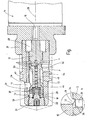
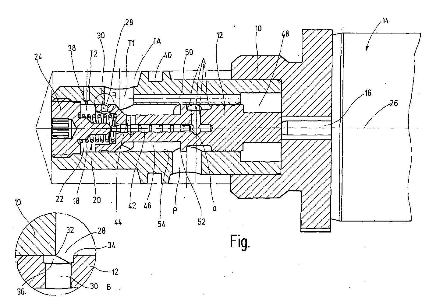
- the only one shows Figure in a schematic and not to scale representation, partly in view, partly in section, a longitudinal view through the invention Valve, in particular pressure control valve, being in the direction of the Figure lower left in an enlarged view and denoted by B, the circular section B is reproduced according to the longitudinal representation.
- the valve shown in the figure has a designated as a whole with 10 Valve body on in the manner of a screw-in cartridge, so that the valve via an external thread in a valve seat with fluid guides (not shown) can screw.
- a main or valve piston 12 is arranged within the valve housing 10 .
- the valve piston 12 serves as a whole with 14 designated magnet system, which is only partially shown in the figure.
- the magnet system 14 energized from the outside is a non-illustrated magnetic coil energized, which actuates a magnet armature, not shown, the again via an actuating plunger 16 on the main or valve piston 12 acts accordingly.
- the pertinent structure of a magnetic actuation system is common, so that at this point not closer will be received.
- the magnet system 14 of the valve leads depending on the height of the control current, the can be fed via a common connection point, a stroke against the force a spring accumulator in the form of the compression spring 18 from including the force due to the force-effective surface of a pressure signaling piston 42.
- the system pressure at the port P of the valve can via a hydraulic Constant pump od.
- the inventive Valve as a whole with 20 designated hydraulic Damping device on.
- the hydraulic damping device 20 of the Valve according to the invention is filled with a fluid damping space 22 provided, the outward to the environment from a stopper 24 is limited, which at the one free end of the valve housing 10 in this screwed and can be fixed.
- valve housing 10 On the opposite Side is the damping chamber 22 from the free end of the Ventililtilgepuruses 10. Furthermore, the valve housing 10 is of a first Tank connection T1 penetrated and from another tank connection T2. Both tank connections T1, T2 open with their free pointing outwards End in a common tank connection room TA.
- the single ones Tank connections T1, T2 may consist of several holes, preferably to the longitudinal axis 26 of the valve diametrically opposite each other pass through the valve housing 10. Further, the bore diameter the tank port T1 greater than that of the tank port T2.
- the valve piston 12 Towards the front end of the valve piston 12, these parts of a Throttle 28, the valve piston 12 in the manner of at least one Bore 30 passes through.
- the throttle is in enlargement B shown accordingly.
- the magnification B is the throttle point 28 formed by two circumferential control edges 32,34, wherein the control edge 32 is assigned to the valve housing 10 and the control edge 34 the valve piston 12.
- the valve piston 12 is on the outer peripheral side with a cross-section provided rectangular annular groove 36, in which the respective bore 30 opens.
- the free variable changes Cross-section for the throttle 28.
- the further tank connection T2 is likewise provided with a throttle point 38, however, their free opening cross-section is fixed and not in operation the valve is changeable. Due to the second tank connection T2 can nach textilen in the damping chamber 22 under tank pressure fluid, if seen in the direction of the figure, the main piston 12th contrary to the magnetic force of the magnet system 14 in its opening position emotional. Finds a movement of the for a damping process Main or valve piston 12 in the opposite direction, it is possible, superfluous damping fluid in the damping chamber 22 via the Throttle 28 in the valve piston 12 itself in the first tank port T1 with regard to the larger free cross section of the variable throttle 28 here a displacement rather than on the other Throttle 38 with smaller opening cross section at the second tank connection T2.
- the already mentioned tank connection space TA is through the gap formed between the valve installation space shown in dashed lines and the actual valve, in the present embodiment is designed as Einschraubpatrone.
- a valve receptacle not shown, an external thread But also serve on the valve body arranged flange, which then the Passing through Feumbleeschn, such as screws od. Like., Serve.
- the valve housing 10 widens according to the embodiment shown gradually in the direction of the magnet system 14 and is provided with a recess 40 provided for the purpose of recording not shown Sealing means, the sealing of the valve housing 10 with respect to the Ensure valve intake.
- a so-called pressure signaling piston 42 led Centered within the cylindrical valve piston 12 is a so-called pressure signaling piston 42 led, with its one free end to a rod-like Extension of the stopper 24 is supported and with his other free end via the pump port P with fluid pressure acted upon is.
- a further sealing is not provided next to the annular gap, so that a leakage current is possible between the pump connection P and the first tank port T1 via the connection gap between the interior of the main piston 12 and the outer periphery of the pressure signaling piston 42, provided that this longitudinally movable within the valve piston 12th engages in the aforementioned area. So that the leakage current over the Pump port P can enter the tank port T1 is in the valve piston 12, a transverse channel 44 is arranged, in which the pressure signaling piston 42nd opens with its annular grooves accordingly.
- the tank connections T1 and T2 consist, as already explained, of several, the outside circumference along the valve housing 10 in each case the same Plane offset and extending connection holes. Furthermore, extends for a fluid-conducting connection between the pump port P and the first tank port T1 along the valve piston 12 at least one connecting channel 46, which also consists of a circumferential Ring groove can be formed. Furthermore, there is inside the valve housing 10 within the wall thereof between the first tank port T1 and an actuating chamber 48, a pressure equalization connection 50 to the free mobility of the valve or main piston 12 in To allow dependence on its respective regulatory position.
- valve piston 12 controls via a radially projecting control edge 52 in connection with the cylindrical associated inner peripheral surface 54 of the valve body 10 the Main fluid flow between pump port P and first tank port T1, which is guided via the connecting channel 46.
- valve according to the invention is a proportional pressure relief valve realized, with the damping of the valve depending on the valve is.
- This is ultimately realized by a valve piston 12 arranged in the Throttle or throttle bore 28,30, over the working stroke of the piston 12 is variable from the free flow area and forth such as the variable damping ratio reflects.
- Throttle 38 in the second tank port T2 is independent of the valve Connection of the damping chamber 22 realized to the tank pressure level, which reflects the constant damping rate of the valve.
- a Leakage compensation can be within the valve piston 12 via the Cross channel 44 done.
- valve solution according to the invention is therefore a hydrodynamic, leakage compensated, over the Valve lift achieves variable damping for one valve, using this in the longitudinal direction 26 of the valve only two tank connections T1, T2 are necessary and a introduced into the valve piston throttle 28.
- This is the free Fluid paths within the valve shortens what the transient and dynamic behavior the valve significantly improved.
- the invention builds Solution especially in the longitudinal axis 26 of the valve small on, so that in particular the valve in the motor vehicle area, where basically cramped installation conditions are present, is very easy to use.
Landscapes
- Engineering & Computer Science (AREA)
- General Engineering & Computer Science (AREA)
- Mechanical Engineering (AREA)
- Physics & Mathematics (AREA)
- Fluid Mechanics (AREA)
- Safety Valves (AREA)
- Magnetically Actuated Valves (AREA)
- Fluid-Driven Valves (AREA)
- Fluid-Damping Devices (AREA)
Abstract
Description
Claims (10)
- Ventil, insbesondere Druckregelventil, mit einem mindestens einen Pumpenanschluß (P) und einen ersten sowie einen zweiten Tankanschluß (T1,T2) aufweisenden Ventilgehäuse (10), in dem ein insbesondere von einem Magnetsystem (14) ansteuerbarer Ventilkolben (12) geführt ist und das mit einer hydraulischen Dämpfungseinrichtung (20) mit einem Dämpfungsraum (22) versehen ist, wobei mittels einer Drossel (28) das Innere des Dämpfungsraumes (22) mit dem ersten Tankanschluß (T1) verbindbar ist, dadurch gekennzeichnet, dass Teile der Drossel (28) den Ventilkolben (12) in der Art mindestens einer Bohrung durchgreifen.
- Ventil nach Anspruch 1, dadurch gekennzeichnet, dass mit zunehmendem Verfahrweg des Ventilkolbens (12) in Richtung des zweiten Tankanschlusses (T2) der freie Querschnitt der Drossel (28) im Ventilkolben (12) sich verringert.
- Ventil nach Anspruch 1 oder 2, dadurch gekennzeichnet, dass die Begrenzungswände der jeweiligen Bohrung für den ersten Tankanschluß (T1) und für die innerhalb des Ventilkörpers (12) verlaufenden Teile (30) der Drossel (28) jeweils eine Regelkante (32,34) der Drossel (28) ausbilden.
- Ventil nach Anspruch 3, dadurch gekennzeichnet, dass der Ventilkolben (12) außenumfangsseitig mit einer Ringnut (36) versehen ist, in die die Teile der Drossel (28) insbesondere in der Art der jeweiligen Bohrung (30) münden, und dass die dem ersten Tankanschluß (T1) zugewandte Seite der Ringnut (36) eine der Regelkanten (34) ist.
- Ventil nach einem der Ansprüche 1 bis 4, dadurch gekennzeichnet, dass die eine Drossel (28) über einen veränderlichen Querschnitt verfügt und dass eine zweite Drossel (38) im zweiten Tankanschluß (T2) mit fest vorgegebenem Querschnitt angeordnet ist.
- Ventil nach einem der Ansprüche 1 bis 5, dadurch gekennzeichnet, dass alle Tankanschlüsse (T1,T2) in einen gemeinsamen Tankanschluß (TA) münden.
- Ventil nach einem der Ansprüche 1 bis 6, dadurch gekennzeichnet, dass innerhalb des Ventilkolbens (12) ein Druckmeldekolben (42) geführt ist, der sich mit seinem einen freien Ende am Ventilgehäuse (10) abstützt und mit seinem anderen freien Ende über den Pumpenanschluß (P) mit Fluiddruck beaufschlagbar ist.
- Ventil nach einem der Ansprüche 1 bis 7, dadurch gekennzeichnet, dass zwischen dem Ventilgehäuse (10) und dem Ventilkolben (12) ein in Richtung einer voll geöffneten Stellung der ersten Drossel (28) wirkendes Kraftspeicherelement, insbesondere in Form einer Druckfeder (18), angeordnet ist.
- Ventil nach einem der Ansprüche 1 bis 8, dadurch gekennzeichnet, dass für eine fluidführende Verbindung zwischen dem Pumpenanschluß (P) und dem ersten Tankanschluß (T1) entlang des Ventilkolbens (12) sich mindestens ein Verbindungskanal (46) erstreckt.
- Ventil nach einem der Ansprüche 1 bis 9, dadurch gekennzeichnet, dass innerhalb des Ventilgehäuses (10) zwischen dem ersten Tankanschluß (T1) und einem Betätigungsraum (48) für den Ventilkolben (12) eine Druckausgleichsverbindung (50) besteht.
Applications Claiming Priority (2)
| Application Number | Priority Date | Filing Date | Title |
|---|---|---|---|
| DE102004012711 | 2004-03-16 | ||
| DE200410012711 DE102004012711A1 (de) | 2004-03-16 | 2004-03-16 | Ventil, insbesondere Druckregelventil |
Publications (3)
| Publication Number | Publication Date |
|---|---|
| EP1577565A2 true EP1577565A2 (de) | 2005-09-21 |
| EP1577565A3 EP1577565A3 (de) | 2011-10-05 |
| EP1577565B1 EP1577565B1 (de) | 2012-10-31 |
Family
ID=34833130
Family Applications (1)
| Application Number | Title | Priority Date | Filing Date |
|---|---|---|---|
| EP20050002345 Expired - Lifetime EP1577565B1 (de) | 2004-03-16 | 2005-02-04 | Ventil, insbesondere Druckregelventil |
Country Status (2)
| Country | Link |
|---|---|
| EP (1) | EP1577565B1 (de) |
| DE (1) | DE102004012711A1 (de) |
Cited By (4)
| Publication number | Priority date | Publication date | Assignee | Title |
|---|---|---|---|---|
| CN101642598A (zh) * | 2008-08-05 | 2010-02-10 | 北京谊安医疗系统股份有限公司 | 气道压力安全阀 |
| CN103104567A (zh) * | 2013-01-11 | 2013-05-15 | 西南交通大学 | 一种双活塞独立阻尼减振调压设备 |
| CN104520620A (zh) * | 2012-08-13 | 2015-04-15 | 罗伯特·博世有限公司 | 限压阀和静液压式行走驱动装置 |
| CN114484247A (zh) * | 2021-12-31 | 2022-05-13 | 广西玉柴重工有限公司 | 一种伐木机可调喷油泵 |
Families Citing this family (2)
| Publication number | Priority date | Publication date | Assignee | Title |
|---|---|---|---|---|
| DE102009012752A1 (de) * | 2009-03-12 | 2010-09-16 | Rapa Rausch & Pausch Gmbh | Ventil |
| EP2558758B1 (de) | 2010-04-10 | 2016-05-18 | Hydac Fluidtechnik GmbH | Stromregelventil |
Family Cites Families (4)
| Publication number | Priority date | Publication date | Assignee | Title |
|---|---|---|---|---|
| US2672882A (en) * | 1949-09-30 | 1954-03-23 | Theodore W Bergquist | Safety valve |
| DE8704819U1 (de) * | 1987-04-01 | 1988-07-28 | Robert Bosch Gmbh, 7000 Stuttgart | Hydraulisches, entsperrbares Rückschlagventil |
| US5509448A (en) * | 1994-11-15 | 1996-04-23 | General Motors Corporation | Control valve with integral accumulator |
| DE19949234B4 (de) * | 1999-10-13 | 2004-04-29 | Hydac Electronic Gmbh | Ventil, insbesondere Druckregelventil |
-
2004
- 2004-03-16 DE DE200410012711 patent/DE102004012711A1/de not_active Withdrawn
-
2005
- 2005-02-04 EP EP20050002345 patent/EP1577565B1/de not_active Expired - Lifetime
Cited By (7)
| Publication number | Priority date | Publication date | Assignee | Title |
|---|---|---|---|---|
| CN101642598A (zh) * | 2008-08-05 | 2010-02-10 | 北京谊安医疗系统股份有限公司 | 气道压力安全阀 |
| CN101642598B (zh) * | 2008-08-05 | 2012-12-12 | 北京谊安医疗系统股份有限公司 | 气道压力安全阀 |
| CN104520620A (zh) * | 2012-08-13 | 2015-04-15 | 罗伯特·博世有限公司 | 限压阀和静液压式行走驱动装置 |
| CN104520620B (zh) * | 2012-08-13 | 2017-02-22 | 罗伯特·博世有限公司 | 限压阀和静液压式行走驱动装置 |
| CN103104567A (zh) * | 2013-01-11 | 2013-05-15 | 西南交通大学 | 一种双活塞独立阻尼减振调压设备 |
| CN103104567B (zh) * | 2013-01-11 | 2015-08-05 | 西南交通大学 | 一种双活塞独立阻尼减振调压设备 |
| CN114484247A (zh) * | 2021-12-31 | 2022-05-13 | 广西玉柴重工有限公司 | 一种伐木机可调喷油泵 |
Also Published As
| Publication number | Publication date |
|---|---|
| EP1577565B1 (de) | 2012-10-31 |
| EP1577565A3 (de) | 2011-10-05 |
| DE102004012711A1 (de) | 2005-10-06 |
Similar Documents
| Publication | Publication Date | Title |
|---|---|---|
| DE102009061003B4 (de) | Verstellbare Dämpfventileinrichtung | |
| EP0534075B1 (de) | Hydraulischer regelbarer Schwingungsdämpfer | |
| EP0400395B1 (de) | Stossdämpfer | |
| DE19711293C2 (de) | Hydraulischer Schwingungsdämpfer mit einstellbarer Dämpfungskraft | |
| DE602005005916T2 (de) | Elektromagnetisches Ventil | |
| EP3631234B1 (de) | Regelbarer schwingungsdämpfer | |
| DE102007005466A1 (de) | Elektrisch ansteuerbares Ventil | |
| DE19914504A1 (de) | Hydraulischer Schwingungsdämpfer mit einstellbarer Dämpfungskraft | |
| DE3434566C2 (de) | ||
| WO2004036057A2 (de) | Steuerbares magnetventil | |
| EP1591856B1 (de) | Druckregelventil | |
| EP0836982A2 (de) | Dämpferventil | |
| DE102007005465A1 (de) | Elektrisch ansteuerbares Ventil | |
| EP2243979A2 (de) | Verstellbarer Schwingungsdämpfer mit einem Notbetriebventil | |
| EP0599045A2 (de) | Regelbarer hydraulischer Schwingungsdämpfer | |
| DE19949234B4 (de) | Ventil, insbesondere Druckregelventil | |
| EP1577565B1 (de) | Ventil, insbesondere Druckregelventil | |
| DE102011013176A1 (de) | Mechanisch entsperrbares Sperrventil mit Druckentlastung | |
| WO2013135450A1 (de) | Druckregelventil zur druckregelung in einem kraftstoff - hochdruckspeicher brennkraftmaschine | |
| EP0630452B1 (de) | Proportional-wegeventil | |
| DE102016105203A1 (de) | Hydraulisches Wegeventil | |
| WO2022106168A1 (de) | Ventil | |
| EP1332290B1 (de) | Vorgesteuertes druckabschaltventil und vorsteuerventilanordnung dafür | |
| EP1001196B1 (de) | Druckbegrenzungsventil, insbesondere für Fahrzeuge | |
| DE102006036615B4 (de) | Steuerbares Magnetventil |
Legal Events
| Date | Code | Title | Description |
|---|---|---|---|
| PUAI | Public reference made under article 153(3) epc to a published international application that has entered the european phase |
Free format text: ORIGINAL CODE: 0009012 |
|
| AK | Designated contracting states |
Kind code of ref document: A2 Designated state(s): AT BE BG CH CY CZ DE DK EE ES FI FR GB GR HU IE IS IT LI LT LU MC NL PL PT RO SE SI SK TR |
|
| AX | Request for extension of the european patent |
Extension state: AL BA HR LV MK YU |
|
| PUAL | Search report despatched |
Free format text: ORIGINAL CODE: 0009013 |
|
| AK | Designated contracting states |
Kind code of ref document: A3 Designated state(s): AT BE BG CH CY CZ DE DK EE ES FI FR GB GR HU IE IS IT LI LT LU MC NL PL PT RO SE SI SK TR |
|
| AX | Request for extension of the european patent |
Extension state: AL BA HR LV MK YU |
|
| RIC1 | Information provided on ipc code assigned before grant |
Ipc: F16K 31/06 20060101ALI20110831BHEP Ipc: F16K 17/06 20060101ALI20110831BHEP Ipc: F15B 13/044 20060101AFI20110831BHEP |
|
| 17P | Request for examination filed |
Effective date: 20111221 |
|
| RIC1 | Information provided on ipc code assigned before grant |
Ipc: F16K 31/06 20060101ALI20120323BHEP Ipc: F16K 17/06 20060101ALI20120323BHEP Ipc: F15B 13/044 20060101AFI20120323BHEP |
|
| GRAJ | Information related to disapproval of communication of intention to grant by the applicant or resumption of examination proceedings by the epo deleted |
Free format text: ORIGINAL CODE: EPIDOSDIGR1 |
|
| GRAP | Despatch of communication of intention to grant a patent |
Free format text: ORIGINAL CODE: EPIDOSNIGR1 |
|
| GRAP | Despatch of communication of intention to grant a patent |
Free format text: ORIGINAL CODE: EPIDOSNIGR1 |
|
| AKX | Designation fees paid |
Designated state(s): AT BE BG CH CY CZ DE DK EE ES FI FR GB GR HU IE IS IT LI LT LU MC NL PL PT RO SE SI SK TR |
|
| GRAS | Grant fee paid |
Free format text: ORIGINAL CODE: EPIDOSNIGR3 |
|
| GRAA | (expected) grant |
Free format text: ORIGINAL CODE: 0009210 |
|
| AK | Designated contracting states |
Kind code of ref document: B1 Designated state(s): AT BE BG CH CY CZ DE DK EE ES FI FR GB GR HU IE IS IT LI LT LU MC NL PL PT RO SE SI SK TR |
|
| REG | Reference to a national code |
Ref country code: GB Ref legal event code: FG4D Free format text: NOT ENGLISH Ref country code: CH Ref legal event code: EP |
|
| REG | Reference to a national code |
Ref country code: AT Ref legal event code: REF Ref document number: 582172 Country of ref document: AT Kind code of ref document: T Effective date: 20121115 |
|
| REG | Reference to a national code |
Ref country code: IE Ref legal event code: FG4D Free format text: LANGUAGE OF EP DOCUMENT: GERMAN |
|
| REG | Reference to a national code |
Ref country code: DE Ref legal event code: R096 Ref document number: 502005013216 Country of ref document: DE Effective date: 20121227 |
|
| REG | Reference to a national code |
Ref country code: LT Ref legal event code: MG4D |
|
| REG | Reference to a national code |
Ref country code: NL Ref legal event code: VDEP Effective date: 20121031 |
|
| PG25 | Lapsed in a contracting state [announced via postgrant information from national office to epo] |
Ref country code: SE Free format text: LAPSE BECAUSE OF FAILURE TO SUBMIT A TRANSLATION OF THE DESCRIPTION OR TO PAY THE FEE WITHIN THE PRESCRIBED TIME-LIMIT Effective date: 20121031 Ref country code: FI Free format text: LAPSE BECAUSE OF FAILURE TO SUBMIT A TRANSLATION OF THE DESCRIPTION OR TO PAY THE FEE WITHIN THE PRESCRIBED TIME-LIMIT Effective date: 20121031 Ref country code: NL Free format text: LAPSE BECAUSE OF FAILURE TO SUBMIT A TRANSLATION OF THE DESCRIPTION OR TO PAY THE FEE WITHIN THE PRESCRIBED TIME-LIMIT Effective date: 20121031 Ref country code: LT Free format text: LAPSE BECAUSE OF FAILURE TO SUBMIT A TRANSLATION OF THE DESCRIPTION OR TO PAY THE FEE WITHIN THE PRESCRIBED TIME-LIMIT Effective date: 20121031 Ref country code: ES Free format text: LAPSE BECAUSE OF FAILURE TO SUBMIT A TRANSLATION OF THE DESCRIPTION OR TO PAY THE FEE WITHIN THE PRESCRIBED TIME-LIMIT Effective date: 20130211 Ref country code: IS Free format text: LAPSE BECAUSE OF FAILURE TO SUBMIT A TRANSLATION OF THE DESCRIPTION OR TO PAY THE FEE WITHIN THE PRESCRIBED TIME-LIMIT Effective date: 20130228 |
|
| PG25 | Lapsed in a contracting state [announced via postgrant information from national office to epo] |
Ref country code: CY Free format text: LAPSE BECAUSE OF FAILURE TO SUBMIT A TRANSLATION OF THE DESCRIPTION OR TO PAY THE FEE WITHIN THE PRESCRIBED TIME-LIMIT Effective date: 20121031 Ref country code: PL Free format text: LAPSE BECAUSE OF FAILURE TO SUBMIT A TRANSLATION OF THE DESCRIPTION OR TO PAY THE FEE WITHIN THE PRESCRIBED TIME-LIMIT Effective date: 20121031 Ref country code: PT Free format text: LAPSE BECAUSE OF FAILURE TO SUBMIT A TRANSLATION OF THE DESCRIPTION OR TO PAY THE FEE WITHIN THE PRESCRIBED TIME-LIMIT Effective date: 20130228 Ref country code: SI Free format text: LAPSE BECAUSE OF FAILURE TO SUBMIT A TRANSLATION OF THE DESCRIPTION OR TO PAY THE FEE WITHIN THE PRESCRIBED TIME-LIMIT Effective date: 20121031 Ref country code: GR Free format text: LAPSE BECAUSE OF FAILURE TO SUBMIT A TRANSLATION OF THE DESCRIPTION OR TO PAY THE FEE WITHIN THE PRESCRIBED TIME-LIMIT Effective date: 20130201 |
|
| PG25 | Lapsed in a contracting state [announced via postgrant information from national office to epo] |
Ref country code: CZ Free format text: LAPSE BECAUSE OF FAILURE TO SUBMIT A TRANSLATION OF THE DESCRIPTION OR TO PAY THE FEE WITHIN THE PRESCRIBED TIME-LIMIT Effective date: 20121031 Ref country code: EE Free format text: LAPSE BECAUSE OF FAILURE TO SUBMIT A TRANSLATION OF THE DESCRIPTION OR TO PAY THE FEE WITHIN THE PRESCRIBED TIME-LIMIT Effective date: 20121031 Ref country code: DK Free format text: LAPSE BECAUSE OF FAILURE TO SUBMIT A TRANSLATION OF THE DESCRIPTION OR TO PAY THE FEE WITHIN THE PRESCRIBED TIME-LIMIT Effective date: 20121031 Ref country code: SK Free format text: LAPSE BECAUSE OF FAILURE TO SUBMIT A TRANSLATION OF THE DESCRIPTION OR TO PAY THE FEE WITHIN THE PRESCRIBED TIME-LIMIT Effective date: 20121031 Ref country code: BG Free format text: LAPSE BECAUSE OF FAILURE TO SUBMIT A TRANSLATION OF THE DESCRIPTION OR TO PAY THE FEE WITHIN THE PRESCRIBED TIME-LIMIT Effective date: 20130131 |
|
| PG25 | Lapsed in a contracting state [announced via postgrant information from national office to epo] |
Ref country code: RO Free format text: LAPSE BECAUSE OF FAILURE TO SUBMIT A TRANSLATION OF THE DESCRIPTION OR TO PAY THE FEE WITHIN THE PRESCRIBED TIME-LIMIT Effective date: 20121031 Ref country code: IT Free format text: LAPSE BECAUSE OF FAILURE TO SUBMIT A TRANSLATION OF THE DESCRIPTION OR TO PAY THE FEE WITHIN THE PRESCRIBED TIME-LIMIT Effective date: 20121031 |
|
| BERE | Be: lapsed |
Owner name: HYDAC ELECTRONIC G.M.B.H. Effective date: 20130228 |
|
| PLBE | No opposition filed within time limit |
Free format text: ORIGINAL CODE: 0009261 |
|
| STAA | Information on the status of an ep patent application or granted ep patent |
Free format text: STATUS: NO OPPOSITION FILED WITHIN TIME LIMIT |
|
| PG25 | Lapsed in a contracting state [announced via postgrant information from national office to epo] |
Ref country code: MC Free format text: LAPSE BECAUSE OF NON-PAYMENT OF DUE FEES Effective date: 20130228 |
|
| REG | Reference to a national code |
Ref country code: CH Ref legal event code: PL |
|
| 26N | No opposition filed |
Effective date: 20130801 |
|
| GBPC | Gb: european patent ceased through non-payment of renewal fee |
Effective date: 20130204 |
|
| PG25 | Lapsed in a contracting state [announced via postgrant information from national office to epo] |
Ref country code: CH Free format text: LAPSE BECAUSE OF NON-PAYMENT OF DUE FEES Effective date: 20130228 Ref country code: LI Free format text: LAPSE BECAUSE OF NON-PAYMENT OF DUE FEES Effective date: 20130228 |
|
| REG | Reference to a national code |
Ref country code: FR Ref legal event code: ST Effective date: 20131031 |
|
| REG | Reference to a national code |
Ref country code: DE Ref legal event code: R097 Ref document number: 502005013216 Country of ref document: DE Effective date: 20130801 |
|
| REG | Reference to a national code |
Ref country code: IE Ref legal event code: MM4A |
|
| PG25 | Lapsed in a contracting state [announced via postgrant information from national office to epo] |
Ref country code: FR Free format text: LAPSE BECAUSE OF NON-PAYMENT OF DUE FEES Effective date: 20130228 Ref country code: IE Free format text: LAPSE BECAUSE OF NON-PAYMENT OF DUE FEES Effective date: 20130204 Ref country code: BE Free format text: LAPSE BECAUSE OF NON-PAYMENT OF DUE FEES Effective date: 20130228 Ref country code: GB Free format text: LAPSE BECAUSE OF NON-PAYMENT OF DUE FEES Effective date: 20130204 |
|
| REG | Reference to a national code |
Ref country code: AT Ref legal event code: MM01 Ref document number: 582172 Country of ref document: AT Kind code of ref document: T Effective date: 20130204 |
|
| PG25 | Lapsed in a contracting state [announced via postgrant information from national office to epo] |
Ref country code: AT Free format text: LAPSE BECAUSE OF NON-PAYMENT OF DUE FEES Effective date: 20130204 |
|
| PG25 | Lapsed in a contracting state [announced via postgrant information from national office to epo] |
Ref country code: TR Free format text: LAPSE BECAUSE OF FAILURE TO SUBMIT A TRANSLATION OF THE DESCRIPTION OR TO PAY THE FEE WITHIN THE PRESCRIBED TIME-LIMIT Effective date: 20121031 |
|
| PG25 | Lapsed in a contracting state [announced via postgrant information from national office to epo] |
Ref country code: HU Free format text: LAPSE BECAUSE OF FAILURE TO SUBMIT A TRANSLATION OF THE DESCRIPTION OR TO PAY THE FEE WITHIN THE PRESCRIBED TIME-LIMIT; INVALID AB INITIO Effective date: 20050204 Ref country code: LU Free format text: LAPSE BECAUSE OF NON-PAYMENT OF DUE FEES Effective date: 20130204 |
|
| PGFP | Annual fee paid to national office [announced via postgrant information from national office to epo] |
Ref country code: DE Payment date: 20230228 Year of fee payment: 19 |
|
| REG | Reference to a national code |
Ref country code: DE Ref legal event code: R119 Ref document number: 502005013216 Country of ref document: DE |
|
| PG25 | Lapsed in a contracting state [announced via postgrant information from national office to epo] |
Ref country code: DE Free format text: LAPSE BECAUSE OF NON-PAYMENT OF DUE FEES Effective date: 20240903 |
|
| PG25 | Lapsed in a contracting state [announced via postgrant information from national office to epo] |
Ref country code: DE Free format text: LAPSE BECAUSE OF NON-PAYMENT OF DUE FEES Effective date: 20240903 |