EP1577239A2 - Feeder for a punching or stamping device - Google Patents
Feeder for a punching or stamping device Download PDFInfo
- Publication number
- EP1577239A2 EP1577239A2 EP05101440A EP05101440A EP1577239A2 EP 1577239 A2 EP1577239 A2 EP 1577239A2 EP 05101440 A EP05101440 A EP 05101440A EP 05101440 A EP05101440 A EP 05101440A EP 1577239 A2 EP1577239 A2 EP 1577239A2
- Authority
- EP
- European Patent Office
- Prior art keywords
- punching
- embossing device
- feeder
- sheets
- stack
- Prior art date
- Legal status (The legal status is an assumption and is not a legal conclusion. Google has not performed a legal analysis and makes no representation as to the accuracy of the status listed.)
- Granted
Links
Images


Classifications
-
- B—PERFORMING OPERATIONS; TRANSPORTING
- B65—CONVEYING; PACKING; STORING; HANDLING THIN OR FILAMENTARY MATERIAL
- B65H—HANDLING THIN OR FILAMENTARY MATERIAL, e.g. SHEETS, WEBS, CABLES
- B65H3/00—Separating articles from piles
- B65H3/08—Separating articles from piles using pneumatic force
- B65H3/0808—Suction grippers
- B65H3/0816—Suction grippers separating from the top of pile
-
- B—PERFORMING OPERATIONS; TRANSPORTING
- B65—CONVEYING; PACKING; STORING; HANDLING THIN OR FILAMENTARY MATERIAL
- B65H—HANDLING THIN OR FILAMENTARY MATERIAL, e.g. SHEETS, WEBS, CABLES
- B65H11/00—Feed tables
- B65H11/002—Feed tables incorporating transport belts
-
- B—PERFORMING OPERATIONS; TRANSPORTING
- B65—CONVEYING; PACKING; STORING; HANDLING THIN OR FILAMENTARY MATERIAL
- B65H—HANDLING THIN OR FILAMENTARY MATERIAL, e.g. SHEETS, WEBS, CABLES
- B65H3/00—Separating articles from piles
- B65H3/44—Simultaneously, alternately, or selectively separating articles from two or more piles
-
- B—PERFORMING OPERATIONS; TRANSPORTING
- B65—CONVEYING; PACKING; STORING; HANDLING THIN OR FILAMENTARY MATERIAL
- B65H—HANDLING THIN OR FILAMENTARY MATERIAL, e.g. SHEETS, WEBS, CABLES
- B65H35/00—Delivering articles from cutting or line-perforating machines; Article or web delivery apparatus incorporating cutting or line-perforating devices, e.g. adhesive tape dispensers
- B65H35/0006—Article or web delivery apparatus incorporating cutting or line-perforating devices
-
- B—PERFORMING OPERATIONS; TRANSPORTING
- B65—CONVEYING; PACKING; STORING; HANDLING THIN OR FILAMENTARY MATERIAL
- B65H—HANDLING THIN OR FILAMENTARY MATERIAL, e.g. SHEETS, WEBS, CABLES
- B65H2601/00—Problem to be solved or advantage achieved
- B65H2601/40—Increasing or maximizing
- B65H2601/42—Increasing or maximizing entities relating to the handling machine
- B65H2601/421—Capacity
-
- B—PERFORMING OPERATIONS; TRANSPORTING
- B65—CONVEYING; PACKING; STORING; HANDLING THIN OR FILAMENTARY MATERIAL
- B65H—HANDLING THIN OR FILAMENTARY MATERIAL, e.g. SHEETS, WEBS, CABLES
- B65H2601/00—Problem to be solved or advantage achieved
- B65H2601/40—Increasing or maximizing
- B65H2601/42—Increasing or maximizing entities relating to the handling machine
- B65H2601/422—Versatility
Definitions
- the invention relates to a feeder for a punching or embossing device, as well as a Punching or embossing device with such an investor, as well as a method for Punching or embossing sheets with a punching or embossing device.
- Packaging materials made of paper, cardboard, cardboard or corrugated cardboard are mainly used in Sheet format punched. When punching but also crease lines or Blind embossing be introduced into the benefit. This complex process does it indispensable to punch the sheets individually, since it is in the end products usually around demanding packaging. For optimum results are punching tool with lowest tolerances and extremely precise and reliable punching machines required.
- This punching machine is often called flat bed punches, at the printed sheets of the punching machine stacked on a pallet be supplied.
- the bows will be at three points with side and front marks accurately aligned, taken from a gripper carriage with a gripper bar and positioned exactly between die and punching plate.
- the complete bow in a hub punched in the next station (Ausbrechstation) is the waste over Stripping tools removed by machine. (Punching and folding box gluing, solution for the Further Processing, Heidelberger Druckmaschinen AG, 2003).
- the feeder according to the invention is thus characterized in that in the transport direction several stacks are provided side by side, of which the investor by means of suitable Remove the middle sheet and feed it to a punching or embossing device.
- the punching or embossing device Sheet feeds.
- This feeder according to the invention could also consist of two or more conventional, smaller sized Einzelbogenanlegern exist that are parallel to each other operate. For the purposes of the invention, these form a plurality of Einzelbogenanlegern only a feeder according to the invention, so that such embodiments also of of the invention.
- the investor can thereby bow simultaneously from several stacks remove and apply them to the punching and embossing device, although a sequential Peeling off the sheets from different stacks can be advantageous, especially in the With regard to refilling the stacks from which the investor withdraws the sheets.
- a sequential Peeling off the sheets from different stacks can be advantageous, especially in the With regard to refilling the stacks from which the investor withdraws the sheets.
- high Speeds per sheet can be achieved, for example, 14 000 sheets per Hour.
- the performance of the punching device increases accordingly. To this So way, the sheet throughput by the punching or embossing device at the same number of strokes of the punching or embossing device increased by a multiple become.
- the means for Create sheets in such a way that even sheets from a single pile can be applied.
- the punching or embossing device with the same Investors also process those products that were originally for processing with the Punching or embossing device of the appropriate format were intended.
- the investor according to the invention have the means for applying at least one separating sucker per stack.
- This vacuum cleaner per stack is independent of the vacuum cleaner of the other stack operated.
- the means for applying have at least one independent suction head per stack, for sucking the top sheet of the stack. This allows an investor accordingly Claim 1, which only a common suction device over the entire Investor width, to be further educated.
- the investor according to the invention have the means for applying at least one stack associated with the stack Transport element, in particular at least one conveyor belt.
- the transport elements have an independent drive for each stack.
- the Means for applying at least each stack a control roller and / or a sheet flap.
- the Means for applying at least each stack a side mark, for lateral alignment the respective bow.
- the page marks for aligning each Stack also an independent drive on.
- Side marks are operated such that the respective sheets of all the stacks simultaneously be aligned laterally.
- the investor according to the invention have the means for applying at least each stack a front mark on to align the Front of the bow.
- the front marks for aligning the Front of the bow per stack an independent drive on.
- the front marks are operated such that the respective bow all stacks are aligned at the same time.
- the invention also relates to a punching or embossing device, the one inventive investor with one, several or all previous features having.
- the punching or embossing device gripper on a Gripper bar on, for transporting the sheet through the punching or embossing device, wherein Gripper and gripper bar are designed such that the gripper variable at the Gripper bar are attachable.
- the rapier bar by means of variably attachable gripper on the majority of sheets, by side by side arranged stacked, adjust. It can be done this way too advantageously achieve that the gripper an ideal positioning with respect to the edges to take the bow. This can prevent the corners of the bow from being caught Knock punching.
- the punching or Embossing device Fine adjustment means, wherein each stack in the feeder a set of Fine adjustment means are assigned.
- the punching or embossing device comprises the Punching or embossing device Vorstapel Surprise which is designed such that this is suitable for producing a plurality of aligned stacks on a pallet.
- the punching or embossing device is it is in the punching or embossing device to a large-sized punching or Embossing device and the arc to small-sized sheet, in particular a Punching and embossing device for a 105 x 74 format and at the bow to bow of 50x70 format.
- FIG. 1 shows a schematic representation of a known punching or embossing device. 1
- Device required drive and guide means, cams and Control means for illustrating the effects of the device not shown or are described only in general terms.
- FIG. 1 the basic structure of a sheet punching and embossing machine 1 for Punching, breaking and depositing sheets of paper, cardboard and the like shown.
- the punching and embossing machine 1 consists of a punching device 2, a Breakout device 3 and a depositing device 4, of a common Machine housing 5 are supported and enclosed.
- the sheet 6 are mounted on revolving chains 7 gripper bars 8 at their Front edge gripped and intermittently through the various stations 2, 3 and 4 of the Punching and embossing machine 1 pulled through.
- the punching station 2 includes a device consisting of a lower table 9 and an upper table 10.
- the lower table 9 is fixedly mounted in the machine frame and with a Counter plate provided to the punching knife.
- the upper table 10 is mounted vertically movable and driven by a drive for the device.
- the gripper bar 8 transports the sheet 6 of the punching and embossing station 2 in the subsequent stripping station 3, which may be equipped with breakout tools.
- Ausbrechstation 3 are not required with the help of Ausbrechwerkmaschinemaschinemaschinemaschinee Rubs pushed out of the sheet down, causing these waste pieces 11 in fall under the station inserted container-like car 12.
- the depositing station 4 may also include a pallet 13 on which the individual sheets are stacked in the form of a stack 14, so that after reaching a certain stack height, the pallets with the stacked sheet 14 from the Area of the punching and embossing machine 1 can be moved away.
- the chains 7 carry a plurality of gripper bars 8, for example they are here eight, so that several sheets 6 at the same time in the different stations 2, 3 and 4 can be edited.
- FIG. 1 and in FIG. 2 the transport movement of the sheets 6, 6a, 6b through the punching and embossing device 1 represented by the arrow with the reference TB.
- FIG. 2 shown embodiment of the device according to the invention are in the Feeder 30 a first stack 16a and next to a second stack 16b shown.
- the two Stacks 16a, 16b are symmetrical to the centerline M of feeder 30 and punched or Embossing device 1 shown.
- the skilled person is, however, clear that he also needs a not symmetrical arrangement of the stack 16a, 16b can choose, for example, if the two stacks 16a, 16b have different formats.
- feeder 30 a device that the punching or embossing device 1 sheet 6, 6a, 6b supplies.
- This feeder according to the invention could also consist of two or more conventional, smaller sized Einzelbogenanlegern exist that are parallel to each other operate. For the purposes of the invention, however, this is only an inventive Feeder 30 understood, so that such embodiments also from the invention be included.
- suction heads are at the upper end of the stack 16a, 16b 42a, 42b arranged. These suction heads 42a, 42b are equipped with a suction device 40, 40a, 40b connected. It may, in one embodiment, as shown in Figure 3, to a common suction device 40 or, as in the embodiment in Figure 4 shown to each have a suction device 40a, 40b associated with the corresponding stack is. In the embodiment in Figure 3, the suction heads 42a, 42b so with the Suction device 40 may be connected, that the suction heads 42 a, 42 b independently be subjected to suction.
- each stack 16a, 16b has associated therewith 2 suction heads 42a, 42b. the However, it will be apparent to those skilled in the art that it also includes a different number of suction cups 42a, 42b one or three or more per stack can use.
- clock rollers 32 are arranged above the stacks 16a, 16b. These clock rollers 32 generate a scale flow of the sheets 6, 6a, 6b in the direction of the transport movement TB to Punching or embossing device 1.
- the scale flow of the sheet 6, 6a, 6b is through Transport belt pairs 20 moved forward.
- the conveyor belts pairs are advantageously stacked separately driven. But it can also be provided, the Conveyor belts 20, which are associated with the respective stacks 16a, 16b, with each other synchronized by mechanical or electronic means.
- side marks 21a, 21b and not shown known in the art front-end brands for lateral alignment as well as orientation of the front of the sheet 6a, 6b.
- alignment in a preferred embodiment is for all sheets, which are to be punched together in the following, at the same time.
- the sheets 6a, 6b After the sheets 6a, 6b have been aligned, they are gripped by grippers 18a, 18b, which are attached to a gripper bar 8.
- the grippers 18a, 18b are at the Gripper bar 8 slidably mounted, so that the position of the gripper 18 a, 18 b relative to the sheets 6a, 6b can be adjusted, so that a suitable adaptation to format and number of simultaneously processed sheets 6a, 6b is possible.
- the punching or embossing device 1 comprises the Punching or embossing device 1, a stacking device, not shown, the required Number of stacks 16a, 16b generated on a pallet, which then application in the investor 30th Can be found.
Landscapes
- Engineering & Computer Science (AREA)
- Mechanical Engineering (AREA)
- Sheets, Magazines, And Separation Thereof (AREA)
- Perforating, Stamping-Out Or Severing By Means Other Than Cutting (AREA)
- Machines For Manufacturing Corrugated Board In Mechanical Paper-Making Processes (AREA)
- Delivering By Means Of Belts And Rollers (AREA)
- Registering Or Overturning Sheets (AREA)
- Feeding Of Articles By Means Other Than Belts Or Rollers (AREA)
Abstract
Die vorliegende Erfindung betrifft einen Anleger (30) für eine Stanz- oder Prägevorrichtung (1), wobei der Anleger (30) Mittel (20a, 20b, 21a, 21b, 30, 32, 40, 40a, 40b, 42a, 42b) zum Anlegen von Bogen (6, 6a, 6b) von einer Mehrzahl von Stapeln (16a, 16b) aufweist, wobei die Stapel (16a, 16b) nebeneinander in Transportrichtung (TB) angeordnet sind. Zudem betrifft die Erfindung eine Stanz- oder Prägevorrichtung (1), die einen solchen Anleger (30) umfasst, sowie ein Verfahren zum Stanzen oder Prägen von Bogen (6, 6a, 6b) mit einer Stanz- oder Prägevorrichtung (1), wobei verfahrensgemäß Bogen (6, 6a, 6b) von nebeneinander angeordneten Stapeln (16a, 16b) an die Stanz- oder Prägevorrichtung (1) angelegt werden. <IMAGE>The present invention relates to a feeder (30) for a punching or embossing device (1), wherein the feeder (30) comprises means (20a, 20b, 21a, 21b, 30, 32, 40, 40a, 40b, 42a, 42b) for Application of sheets (6, 6a, 6b) from a plurality of stacks (16a, 16b), wherein the stacks (16a, 16b) are arranged side by side in the transport direction (TB). In addition, the invention relates to a punching or embossing device (1) comprising such a feeder (30), and a method for punching or embossing sheets (6, 6a, 6b) with a punching or embossing device (1), according to the method Sheet (6, 6a, 6b) of juxtaposed stacks (16a, 16b) are applied to the punching or embossing device (1). <IMAGE>
Description
Die Erfindung betrifft einen Anleger für eine Stanz- oder Prägevorrichtung, sowie eine Stanz- oder Prägevorrichtung mit einem solchen Anleger, sowie ein Verfahren zum Stanzen oder Prägen von Bogen mit einer Stanz- oder Prägevorrichtung.The invention relates to a feeder for a punching or embossing device, as well as a Punching or embossing device with such an investor, as well as a method for Punching or embossing sheets with a punching or embossing device.
Als Stanzen wird das Schneiden mit in sich geschlossenen, geometrischen Zuschnittsformen bezeichnet, die kreisförmig, oval oder mehreckig sowie Fantasieformen aller Art sein können. Auch die in der Druckweiterverarbeitung geübten Praktiken wie Stanzen mit Locheisen, Ecken abstoßen und Register stanzen werden zu diesem Bereich gezählt. Die Stanzung erfolgt gegen eine Stanzunterlage oder gegen Stempel teilweise sind es auch Schervorgänge (vgl. Druckweiterverarbeitung, Ausbildungsleitfaden für Buchbinder, Bundesverband Druck e.V. 1996, Seite 351 ff.).As punching, cutting becomes self-contained, geometric Designated blank shapes that are circular, oval or polygonal as well as fantasy shapes of all kinds. Also the practices practiced in print finishing such as Punching with punch, repel corners and punching tabs become this area counted. The punching is done against a stamping pad or against stamp partially it also includes shearing operations (see further processing, Training Guidelines for Buchbinder, Bundesverband Druck e.V. 1996, page 351 ff.).
Verpackungsmaterial aus Papier, Karton, Pappe oder Wellpappe werden hauptsächlich in Bogenformat gestanzt. Beim Stanzvorgang können zusätzlich aber auch Rilllinien oder Blindprägungen in den Nutzen eingebracht werden. Dieser komplexe Prozess macht es unabdingbar, die Bogen einzeln zu stanzen, da es sich bei den Endprodukten meist um anspruchsvolle Verpackung handelt. Für optimale Resultate sind Stanzwerkzeug mit geringsten Toleranzen und äußerst präzise und zuverlässig arbeitende Stanzautomaten erforderlich.Packaging materials made of paper, cardboard, cardboard or corrugated cardboard are mainly used in Sheet format punched. When punching but also crease lines or Blind embossing be introduced into the benefit. This complex process does it indispensable to punch the sheets individually, since it is in the end products usually around demanding packaging. For optimum results are punching tool with lowest tolerances and extremely precise and reliable punching machines required.
Bei diesem Stanzautomaten handelt es sich häufig um sogenannte Flachbettstanzen, bei denen die gedruckten und auf einer Palette abgestapelten Bogen der Stanzmaschine zugeführt werden. Die Bogen werden an drei Punkten mit Seiten- und Frontmarken passgenau ausgerichtet, von einem Greiferwagen mit einer Greiferstange übernommen und exakt zwischen Stanzform und Stanzplatte positioniert. Hier wird der komplette Bogen in einem Hub gestanzt in der nächsten Station (Ausbrechstation) wird der Abfall über Ausbrechwerkzeuge maschinell entfernt. (Stanzen und Faltschachtelkleben, Lösung für die Weiterverarbeitung, Heidelberger Druckmaschinen AG, 2003). This punching machine is often called flat bed punches, at the printed sheets of the punching machine stacked on a pallet be supplied. The bows will be at three points with side and front marks accurately aligned, taken from a gripper carriage with a gripper bar and positioned exactly between die and punching plate. Here is the complete bow in a hub punched in the next station (Ausbrechstation) is the waste over Stripping tools removed by machine. (Punching and folding box gluing, solution for the Further Processing, Heidelberger Druckmaschinen AG, 2003).
Die meisten Stanz- und Prägeautomaten bearbeiten großformatige Produkte, etwa in einem Format bis zu 105 x 74 oder 100 x 140. In geringerem Maße werden auch kleine Bogenformate (beispielsweise im Format 50 x 70) verarbeitet. Für diese kleineren Bogenformate werden zum Teil kleine Stanz- oder Prägeautomaten entwickelt und eingesetzt, oder alternativ, wenn die Investition in eine Kleinformatmaschine gescheut wird, die Kleinformate auf großen Maschinen verarbeitet. Letzteres kann zwar wirtschaftlicher sein, als die Anschaffung einer Kleinformatmaschine, allerdings ist die Wirtschaftlichkeit dennoch relativ gering, wenn eine großformatige Maschine lediglich zum Stanzen oder Prägen von kleinformatigen Bogen verwendet wird.Most punching and embossing machines process large-format products, for example in one Format up to 105 x 74 or 100 x 140. To a lesser extent, even small Sheet formats (for example, 50x70) are processed. For these smaller ones Sheet formats are sometimes developed small punching or embossing machines and used, or alternatively, if the investment in a small format machine spared which processes small formats on large machines. The latter can indeed be more economical than the acquisition of a small format machine, however, is the Economy nevertheless relatively low, if a large-format machine only used for punching or embossing small format sheets.
Es ist daher die Aufgabe der vorliegenden Erfindung, das Stanzen oder Prägen von kleinformatigen Bogen mit einer großformatigen Stanz- oder Prägevorrichtung wirtschaftlicher zu machen, und die Leistungsfähigkeit einer großformatigen Stanz- oder Prägevorrichtung für kleine Bogenformate zu erhöhen.It is therefore the object of the present invention, the stamping or embossing of small-format sheet with a large-format punching or embossing device To make more economical, and the performance of a large-sized punching or Increase embossing device for small sheet sizes.
Diese Aufgabe wird mit Hilfe des erfindungsgemäßen Anlegers für eine Stanz- oder
Prägevorrichtung mit den in Anspruch 1 genannten Merkmalen gelöst. Die Erfindung wird
ebenfalls durch eine Stanz- oder Prägevorrichtung mit den Merkmalen in Anspruch 14
sowie durch ein Verfahren zum Stanzen oder Prägen von Bogen mit einer Stanz- oder
Prägevorrichtung mit den Merkmalen des Anspruchs 19 gelöst. Weitere Merkmale ergeben
sich aus den Unteransprüchen.This object is achieved by means of the inventive investor for a punching or
Embossing device solved with the features mentioned in
Der erfindungsgemäße Anleger zeichnet sich also dadurch aus, dass in Transportrichtung mehrere Stapel nebeneinander vorgesehen sind, von denen der Anleger mittels geeigneter Mittel Bogen abzieht und einer Stanz- oder Prägevorrichtung zuführt. Dabei steht hier der Begriff Anleger ganz allgemein für jene Vorrichtung, die der Stanz- oder Prägevorrichtung Bogen zuführt. Dieser erfindungsgemäße Anleger könnte auch aus zwei oder mehr herkömmlichen, kleinerformatigen Einzelbogenanlegern bestehen, die parallel zueinander betrieben werden. Im Sinne der Erfindung bilden diese Mehrzahl an Einzelbogenanlegern nur einen erfindungsgemäßen Anleger, so dass derartige Ausführungsformen ebenfalls von der Erfindung umfasst werden. The feeder according to the invention is thus characterized in that in the transport direction several stacks are provided side by side, of which the investor by means of suitable Remove the middle sheet and feed it to a punching or embossing device. Here it is the Term investor generally for that device, the punching or embossing device Sheet feeds. This feeder according to the invention could also consist of two or more conventional, smaller sized Einzelbogenanlegern exist that are parallel to each other operate. For the purposes of the invention, these form a plurality of Einzelbogenanlegern only a feeder according to the invention, so that such embodiments also of of the invention.
Vorzugsweise kann der Anleger dadurch gleichzeitig von mehreren Stapeln Bogen abziehen und sie der Stanz- und Prägevorrichtung zuführen, obwohl auch ein sequentielles Abziehen der Bogen von unterschiedlichen Stapeln vorteilhaft sein kann, insbesondere im Hinblick auf das Nachfüllen der Stapel, von denen der Anleger die Bogen abzieht. Bereits durch das Vorsehen von zwei Stapeln kann bei gleichzeitigem Abzug der Bogen von den Stapeln und Zuführen zur Stanz- oder Prägevorrichtung eine Verdopplung des Durchsatzes der Stanz- oder Prägevorrichtung erreicht werden, sodass auf diese Art und Weise hohe Geschwindigkeiten pro Bogen erreicht werden können, beispielsweise 14 000 Bogen pro Stunde. Bei drei oder mehr Stapeln, von denen der Anleger die Bogen gleichzeitig abnimmt, erhöht sich die Leistungsfähigkeit der Stanzvorrichtung entsprechend. Auf diese Art und Weise kann also der Bogendurchsatz durch die Stanz- oder Prägevorrichtung bei gleicher Anzahl von Hüben der Stanz- oder Prägevorrichtung um ein Vielfaches erhöht werden.Preferably, the investor can thereby bow simultaneously from several stacks remove and apply them to the punching and embossing device, although a sequential Peeling off the sheets from different stacks can be advantageous, especially in the With regard to refilling the stacks from which the investor withdraws the sheets. Already by the provision of two stacks can at the same time deduction of the bow of the Stacking and feeding to the punching or embossing device doubling the throughput the punching or embossing device can be achieved, so in this way high Speeds per sheet can be achieved, for example, 14 000 sheets per Hour. With three or more stacks, one of which feeds the bow at the same time decreases, the performance of the punching device increases accordingly. To this So way, the sheet throughput by the punching or embossing device at the same number of strokes of the punching or embossing device increased by a multiple become.
In einer vorteilhaften Ausgestaltung des erfindungsgemäßen Anlegers sind die Mittel zum Anlegen von Bogen derart ausgestaltet, dass auch Bogen von einem einzigen Stapel anlegbar sind. Auf diese Weise kann die Stanz- oder Prägevorrichtung mit demselben Anleger auch jene Produkte verarbeiten, die ursprünglich für die Verarbeitung mit der Stanz- oder Prägevorrichtung des entsprechenden Formats gedacht waren.In an advantageous embodiment of the investor according to the invention are the means for Create sheets in such a way that even sheets from a single pile can be applied. In this way, the punching or embossing device with the same Investors also process those products that were originally for processing with the Punching or embossing device of the appropriate format were intended.
In einer weiteren vorteilhaften Ausführungsform des erfindungsgemäßen Anlegers weisen
die Mittel zum Anlegen wenigstens einen Trennsauger pro Stapel auf. Vorteilhafterweise
ist dieser Trennsauger pro Stapel unabhängig von den Trennsaugern der anderen Stapel
betreibbar. In einer weiteren vorteilhaften Ausgestaltung des erfindungsgemäßen Anlegers
weisen die Mittel zum Anlegen wenigstens einen unabhängigen Saugkopf pro Stapel auf,
zum Ansaugen des obersten Bogen des Stapels. Dadurch kann ein Anleger entsprechend
Anspruch 1, der lediglich eine gemeinsame Saugeinrichtung über die gesamte
Anlegerbreite aufweist, weitergebildet werden.In a further advantageous embodiment of the investor according to the invention have
the means for applying at least one separating sucker per stack. advantageously,
This vacuum cleaner per stack is independent of the vacuum cleaner of the other stack
operated. In a further advantageous embodiment of the investor according to the invention
the means for applying have at least one independent suction head per stack,
for sucking the top sheet of the stack. This allows an investor accordingly
In einer weiteren vorteilhaften Ausführungsform des erfindungsgemäßen Anlegers weisen die Mittel zum Anlegen wenigstens je Stapel ein dem Stapel zugeordnetes Transportelement auf, insbesondere wenigstens ein Transportband. Vorteilhafterweise weisen die Transportelemente je Stapel einen unabhängigen Antrieb auf. Dem Fachmann ist jedoch klar, dass auch ein Anlger mit einem Transportelement für alle Bogen von den verschiedenen Stapeln verwendet werden kann.In a further advantageous embodiment of the investor according to the invention have the means for applying at least one stack associated with the stack Transport element, in particular at least one conveyor belt. advantageously, The transport elements have an independent drive for each stack. The expert However, it is clear that a starter with a transport element for all the bow of the different stacks can be used.
In einer weiteren vorteilhaften Ausgestaltung des erfindungsgemäßen Anlegers weisen die Mittel zum Anlegen wenigstens je Stapel eine Taktrolle und/oder eine Bogenklappe auf.In a further advantageous embodiment of the investor according to the invention, the Means for applying at least each stack a control roller and / or a sheet flap.
In einer weiteren vorteilhaften Ausgestaltung des erfindungsgemäßen Anlegers weisen die Mittel zum Anlegen wenigstens je Stapel eine Seitenmarke auf, zur seitlichen Ausrichtung der jeweiligen Bogen. Vorteilhafterweise weisen die Seitenmarken zum Ausrichten je Stapel ebenfalls einen unabhängigen Antrieb auf. Weiterhin können vorteilhafterweise die Seitenmarken derart betrieben werden, dass die jeweiligen Bogen aller Stapel gleichzeitig seitlich ausgerichtet werden.In a further advantageous embodiment of the investor according to the invention, the Means for applying at least each stack a side mark, for lateral alignment the respective bow. Advantageously, the page marks for aligning each Stack also an independent drive on. Furthermore, advantageously Side marks are operated such that the respective sheets of all the stacks simultaneously be aligned laterally.
In einer weiteren vorteilhaften Ausführungsform des erfindungsgemäßen Anlegers weisen die Mittel zum Anlegen wenigstens je Stapel eine Frontmarke auf zum Ausrichten der Frontseite der Bogen. Vorteilhafterweise weisen die Frontmarken zum Ausrichten der Frontseite der Bogen je Stapel einen unabhängigen Antrieb auf. Weiterhin können vorteilhafterweise die Frontmarken derart betrieben werden, dass die jeweiligen Bogen aller Stapel gleichzeitig ausgerichtet werden.In a further advantageous embodiment of the investor according to the invention have the means for applying at least each stack a front mark on to align the Front of the bow. Advantageously, the front marks for aligning the Front of the bow per stack an independent drive on. Furthermore you can Advantageously, the front marks are operated such that the respective bow all stacks are aligned at the same time.
Die Erfindung betrifft ebenfalls eine Stanz- oder Prägevorrichtung, die einen erfindungsgemäßen Anleger mit einem, mehreren oder allen vorangegangenen Merkmalen aufweist. Vorteilhafterweise weist die Stanz- oder Prägevorrichtung Greifer auf einer Greiferstange auf, zum Transport der Bogen durch die Stanz- oder Prägevorrichtung, wobei Greifer und Greiferstange derart ausgestaltet sind, dass die Greifer variabel an der Greiferstange anbringbar sind. Auf diese Weise lässt sich die Greiferstange mittels der variabel anbringbaren Greifer auf die Mehrzahl an Bogen, die von nebeneinander angeordneten Stapeln angelegt werden, anpassen. Es läßt sich auf diese Weise auch vorteilhaft erreichen, dass die Greifer eine ideale Positionierung hinsichtlich der Kanten der Bogen einnehmen können. Dies ist kann verhindern, dass die Ecken der Bogen beim Stanzen umknicken.The invention also relates to a punching or embossing device, the one inventive investor with one, several or all previous features having. Advantageously, the punching or embossing device gripper on a Gripper bar on, for transporting the sheet through the punching or embossing device, wherein Gripper and gripper bar are designed such that the gripper variable at the Gripper bar are attachable. In this way, the rapier bar by means of variably attachable gripper on the majority of sheets, by side by side arranged stacked, adjust. It can be done this way too advantageously achieve that the gripper an ideal positioning with respect to the edges to take the bow. This can prevent the corners of the bow from being caught Knock punching.
In einer vorteilhaften Weiterbildung der Stanz- oder Prägevorrichtung weist die Stanz- oder Prägevorrichtung Feinjustagemittel auf, wobei jedem Stapel im Anleger ein Satz von Feinjustagemitteln zugeordnet sind.In an advantageous embodiment of the punching or embossing device, the punching or Embossing device Fine adjustment means, wherein each stack in the feeder a set of Fine adjustment means are assigned.
In einer weiteren vorteilhaften Ausgestaltung der Stanz- oder Prägevorrichtung umfasst die Stanz- oder Prägevorrichtung eine Vorstapeleinrichtung, die derart ausgestaltet ist, dass diese zur Erzeugung von mehreren ausgerichteten Stapeln auf einer Palette geeignet ist. In einer besonders vorteilhaften Ausführungsform der Stanz- oder Prägevorrichtung handelt es sich bei der Stanz- oder Prägevorrichtung um eine großformatige Stanz- oder Prägevorrichtung und bei den Bogen um kleinformatige Bogen, insbesondere um eine Stanz- und Prägevorrichtung für ein 105 x 74 Format und bei den Bogen um Bogen vom 50 x 70 Format.In a further advantageous embodiment of the punching or embossing device comprises the Punching or embossing device Vorstapeleinrichtung which is designed such that this is suitable for producing a plurality of aligned stacks on a pallet. In a particularly advantageous embodiment of the punching or embossing device is it is in the punching or embossing device to a large-sized punching or Embossing device and the arc to small-sized sheet, in particular a Punching and embossing device for a 105 x 74 format and at the bow to bow of 50x70 format.
Des Weiteren betrifft die Erfindung ein Verfahren zum Stanzen oder Prägen von Bogen mit
einer Stanz- oder Prägevorrichtung mit den Verfahrensschritten:
In einer Weiterbildung dieses erfindungsgemäßen Verfahrens erfolgt das Stanzen der Bogen von unterschiedlichen Stapeln gleichzeitig.In a further development of this method according to the invention, the punching of the Bow of different stacks at the same time.
Bevorzugte Ausführungsformen der erfindungsgemäßen Vorrichtung werden im folgenden unter Bezugnahme auf die Zeichnungen im Einzelnen näher beschrieben. Es zeigen in schematischer Darstellung:
- Fig. 1
- den prinzipiellen Aufbau einer Bogenstanz- und Prägemaschine,
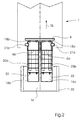
- Fig. 2
- eine Draufsicht einer Ausführungsform eines erfindungsgemäßen Anlegers
- Fig. 3
- eine Vorderansicht einer Ausführungsform eines erfindungsgemäßen Anlegers
- Fig. 4
- eine Vorderansicht einer weiteren Ausführungsform eines erfindungsgemäßen Anlegers
- Fig. 1
- the basic structure of a sheet punching and embossing machine,
- Fig. 2
- a plan view of an embodiment of an investor according to the invention
- Fig. 3
- a front view of an embodiment of an investor according to the invention
- Fig. 4
- a front view of another embodiment of an investor according to the invention
Figur 1 zeigt in schematischer Darstellung eine bekannte Stanz- oder Prägevorrichtung 1. Hier, wie auch in den folgenden Figuren, sind allgemeine bekannte und zum Betrieb der Vorrichtung erforderliche Antriebs- und Führungsmittel, Kurvenscheiben und Steuerungsmittel zur Verdeutlichung der Wirkungsweisen der Vorrichtung nicht dargestellt bzw. werden nur in allgemeiner Form beschrieben.1 shows a schematic representation of a known punching or embossing device. 1 Here, as well as in the following figures, are general well-known and to the operation of Device required drive and guide means, cams and Control means for illustrating the effects of the device not shown or are described only in general terms.
In Figur 1 ist der prinzipielle Aufbau einer Bogenstanz- und Prägemaschine 1 zum
Stanzen, Ausbrechen und Ablegen von Bogen aus Papier, Pappe und dergleichen
dargestellt. Die Stanz- und Prägemaschine 1 besteht aus einer Stanzeinrichtung 2, einer
Ausbrecheinrichtung 3 und einer Ablegeeinrichtung 4, die von einem gemeinsamen
Maschinengehäuse 5 getragen und umschlossen werden.In Figure 1, the basic structure of a sheet punching and embossing
Die Bogen 6 werden von auf umlaufenden Ketten 7 befestigten Greiferstangen 8 an ihrer
Vorderkante ergriffen und intermittierend durch die verschiedenen Stationen 2, 3 und 4 der
Stanz- und Prägemaschine 1 hindurchgezogen.The
Die Stanzstation 2 beinhaltet eine Vorrichtung bestehend aus einem Untertisch 9 und
einem Obertisch 10. Der Untertisch 9 ist fest im Maschinengestell gelagert und mit einer
Gegenplatte zum Stanzmesser versehen. Der Obertisch 10 ist vertikal bewegbar gelagert
und über einen Antrieb für die Vorrichtung antreibbar.The punching
Die Greiferstange 8 transportiert den Bogen 6 von der Stanz- und Prägestation 2 in die
nachfolgende Ausbrechstation 3, die mit Ausbrechwerkzeugen ausgestattet sein kann. In
der Ausbrechstation 3 werden mit Hilfe der Ausbrechwerkzeuge die nicht benötigten
Abfallstücke aus dem Bogen nach unten herausgestoßen, wodurch diese Abfallstücke 11 in
einen unter der Station eingeschobenen behälterartigen Wagen 12 fallen.The
Von der Ausbrechstation 3 gelangt der Bogen 6 in die Ablegestation 4, wo der Bogen
entweder nur einfach abgelegt wird, oder aber günstiger gleichzeitig eine Trennung der
einzelnen Nutzen erfolgt. Die Ablegestation 4 kann auch eine Palette 13 enthalten, auf der
die einzelnen Bogen in Form eines Stapels 14 aufgestapelt werden, so dass nach Erreichen
einer bestimmten Stapelhöhe die Paletten mit den aufgestapelten Bogen 14 aus dem
Bereich der Stanz- und Prägemaschine 1 weggefahren werden können.From the breaking station 3, the
Wie zu erkennen ist, tragen die Ketten 7 mehrere Greiferstangen 8, beispielsweise sind es
hier acht, so dass mehrere Bogen 6 gleichzeitig in den verschiedenen Stationen 2, 3 und 4
bearbeitet werden können.As can be seen, the
In Figur 1 und in Figur 2 ist die Transportbewegung der Bogen 6, 6a, 6b durch die Stanz-
und Prägevorrichtung 1 durch den Pfeil mit dem Bezugszeichen TB dargestellt. In der in
Figur 2 gezeigten Ausführungsform der erfindungsgemäßen Vorrichtung sind in dem
Anleger 30 ein erster Stapel 16a und daneben ein zweiter Stapel 16b gezeigt. Die beiden
Stapel 16a, 16b sind symmetrisch zur Mittellinie M von Anleger 30 und Stanz- oder
Prägevorrichtung 1 gezeigt. Dem Fachmann ist allerdings klar, dass er bei Bedarf auch eine
nicht symmetrische Anordnung der Stapel 16a, 16b wählen kann, beispielsweise wenn die
beiden Stapel 16a, 16b unterschiedliche Formate aufweisen. Im übrigen versteht man hier
unter Anleger 30 eine Vorrichtung, die der Stanz- oder Prägevorrichtung 1 Bogen 6, 6a, 6b
zuführt. Dieser erfindungsgemäße Anleger könnte auch aus zwei oder mehr
herkömmlichen, kleinerformatigen Einzelbogenanlegern bestehen, die parallel zueinander
betrieben werden. Im Sinne der Erfindung wird hierunter aber nur ein erfindungsgemäßer
Anleger 30 verstanden, so dass derartige Ausführungsformen ebenfalls von der Erfindung
umfasst werden. In FIG. 1 and in FIG. 2, the transport movement of the
Wie in Figur 3 und Figur 4 gezeigt, sind am oberen Ende des Stapels 16a, 16b Saugköpfe
42a, 42 b angeordnet. Diese Saugköpfe 42a, 42b sind mit einer Saugeinrichtung 40, 40a,
40b verbunden. Dabei kann es sich in einer Ausführungsform, wie in Figur 3 gezeigt, um
eine gemeinsame Saugeinrichtung 40 handeln oder, wie in der Ausführungsform in Figur 4
gezeigt, um je eine Saugeinrichtung 40a, 40b, die dem entsprechenden Stapel zugeordnet
ist. Bei der Ausführungsform in Figur 3 können die Saugköpfe 42a, 42 b derart mit der
Saugeinrichtung 40 verbunden sein, dass die Saugköpfe 42a, 42 b unabhängig voneinander
mit Saugluft beaufschlagt werden. Die Saugeinrichtung 40, 40a, 40b erzeugt an den
Saugköpfen 42a, 42b einen geeigneten, getakteten Unterdruck, so dass die Saugköpfe 42a,
42b den obersten Bogen 6a, 6b der Stapel 16a, 16b ergreifen und einer
Transporteinrichtung 20a, 20b zuführen können. In den Ausführungsformen der Figuren 3
und 4 sind jedem Stapel 16a, 16b jeweils 2 Saugköpfe 42a, 42b zugeordnet. Dem
Fachmann ist jedoch klar, dass er auch eine andere Anzahl von Saugköpfen 42a, 42b etwa
einen oder drei oder mehrere pro Stapel einsetzen kann.As shown in Fig. 3 and Fig. 4, suction heads are at the upper end of the
Oberhalb der Stapel 16a, 16b sind Taktrollen 32 angeordnet. Diese Taktrollen 32 erzeugen
eine Schuppenstrom der Bogen 6, 6a, 6b in Richtung der Transportbewegung TB zur
Stanz- oder Prägevorrichtung 1. Der Schuppenstrom der Bogen 6, 6a, 6b wird durch
Transportbänderpaare 20 vorwärts bewegt. Die Transportbänderpaare sind
vorteilhafterweise stapelweise separat angetrieben. Es kann aber auch vorgesehen sein, die
Transportbänder 20, die den jeweiligen Stapeln 16a, 16b zugeordnet sind, untereinander
durch mechanische oder elektronische Mittel zu synchronisieren.Above the
Am Eingang der Stanz- oder Prägevorrichtung 1 befinden sich Seitenmarken 21a, 21b
sowie nicht gezeigte, dem Fachmann bekannte Vordermarken zur seitlichen Ausrichtung
sowie Ausrichtung der Frontseite der Bogen 6a, 6b. In einer Ausführungsform sind die
Seitenmarken 21a, 21b bzw. Vordermarken den jeweiligen Stapeln 16a, 16b derart
zugeordnet, dass sie unabhängig voneinander die jeweiligen Bogen 6a, 6b ausrichten.
Allerdings erfolgt die Ausrichtung in einer bevorzugten Ausführungsform für alle Bogen,
die im Folgenden gemeinsam gestanzt werden sollen, gleichzeitig. At the entrance of the punching or
Nachdem die Bogen 6a, 6b ausgerichtet wurden, werden sie von Greifern 18a, 18b erfasst,
die an einer Greiferstange 8 angebracht sind. Die Greifer 18a, 18b sind dabei an der
Greiferstange 8 verschiebbar angebracht, so dass die Position der Greifer 18a, 18b relativ
zu den Bogen 6a, 6b verstellt werden kann, so dass eine geeignete Anpassung an Format
und Anzahl der gleichzeitig zu verarbeitenden Bogen 6a, 6b möglich ist.After the
In einer bevorzugten Ausführungsform der Stanz- oder Prägevorrichtung 1 umfasst die
Stanz- oder Prägevorrichtung 1 eine nicht gezeigte Stapelvorrichtung, die die erforderliche
Anzahl von Stapeln 16a, 16b auf eine Palette erzeugt, die dann Anwendung im Anleger 30
finden kann. In a preferred embodiment of the punching or
- 11
- Stanz- und PrägevorrichtungPunching and embossing device
- 22
- Stanz- und PrägestationPunching and embossing station
- 33
- Ausbrechstationstripping
- 44
- Ablegestationdeposit station
- 55
- Maschinengehäusemachine housing
- 66
- Bogenbow
- 6a, b6a, b
- Bogenbow
- 77
- KetteChain
- 88th
- Greiferstangegripper bar
- 99
- Untertischunder table
- 1010
- Obertischovertable
- 1111
- Abfallstücketrimmings
- 1212
- behälterartiger Wagencontainer-type trolley
- 1313
- Palettepalette
- 1414
- aufgestapelte Bogenstacked sheets
- 16a, b16a, b
- Stapelstack
- 18a, b18a, b
- Greifergrab
- 20a, b20a, b
- Transportbandconveyor belt
- 21a, b21a, b
- Seitenmarkepage brand
- 3030
- Anlegerinvestor
- 3232
- Taktrollesynchronizing roller
- 4040
- Saugeinrichtungsuction
- 40a, b40a, b
- Saugeinrichtungsuction
- 42a, b42a, b
- Saugkopfsuction head
- TBTB
- Transportbewegungtransport movement
- MM
- Mittelliniecenter line
Claims (20)
dadurch gekennzeichnet, dass der Anleger (30) Mittel (20a, 20b, 21a, 21b, 30, 32, 40, 40a, 40b, 42a, 42b) zum Anlegen von Bogen (6, 6a, 6b) von einer Mehrzahl von Stapeln (16a, 16b) aufweist, wobei die Stapel (16a, 16b) nebeneinander in Transportrichtung (TB) angeordnet sind.Feeder (30) for a punching or embossing device (1)
characterized in that the feeder (30) comprises means (20a, 20b, 21a, 21b, 30, 32, 40, 40a, 40b, 42a, 42b) for applying sheets (6, 6a, 6b) from a plurality of stacks (Fig. 16a, 16b), wherein the stacks (16a, 16b) are arranged side by side in the transport direction (TB).
dadurch gekennzeichnet, dass die Mittel (20a, 20b, 21a, 21b, 30, 32, 40, 40a, 40b, 42a, 42b) zum Anlegen derart ausgestaltet sind, dass auch Bogen (6, 6a, 6b) von einem einzigen Stapel (16a, 16b) anlegbar sind.Feeder for a punching or embossing device (1) according to claim 1
characterized in that the means (20a, 20b, 21a, 21b, 30, 32, 40, 40a, 40b, 42a, 42b) for application are designed such that also sheets (6, 6a, 6b) from a single stack ( 16a, 16b) can be applied.
dadurch gekennzeichnet, dass die Mittel (20a, 20b, 21a, 21b, 30, 32, 40, 40a, 40b, 42a, 42b) zum Anlegen wenigstens eine Saugeinrichtung (40, 40a, 40b) pro Stapel (16a, 16b) aufweisen.Feeder for a punching or embossing device (1) according to one of claims 1 to 2
characterized in that the means (20a, 20b, 21a, 21b, 30, 32, 40, 40a, 40b, 42a, 42b) for application comprise at least one suction means (40, 40a, 40b) per stack (16a, 16b).
dadurch gekennzeichnet, dass die Saugeinrichtung (40, 40a, 40b) pro Stapel (16a, 16b) unabhängig voneinander betreibbar sind.Feeder for a punching or embossing device (1) according to claim 3
characterized in that the suction device (40, 40a, 40b) per stack (16a, 16b) are independently operable.
dadurch gekennzeichnet, dass die Mittel (20a, 20b, 21a, 21b, 30, 32, 40, 40a, 40b, 42a, 42b) zum Anlegen wenigstens einen unabhängigen Saugkopf (42a, 42b) pro Stapel (16a, 16b) aufweist, zum Ansaugen des obersten Bogens (6a, 6b) des Stapels (16a, 16b). Feeder for a punching or embossing device (1) according to one of claims 1 to 4
characterized in that the means (20a, 20b, 21a, 21b, 30, 32, 40, 40a, 40b, 42a, 42b) for applying comprises at least one independent suction head (42a, 42b) per stack (16a, 16b), for Sucking the uppermost sheet (6a, 6b) of the stack (16a, 16b).
dadurch gekennzeichnet, dass die Mittel (20a, 20b, 21a, 21b, 30, 32, 40, 40a, 40b, 42a, 42b) zum Anlegen wenigstens je Stapel (16a, 16b) ein Transportelement (20a, 20b) aufweisen, insbesondere wenigstens ein Transportband (20a, 20b).Feeder for a punching or embossing device (1) according to one of claims 1 to 5
characterized in that the means (20a, 20b, 21a, 21b, 30, 32, 40, 40a, 40b, 42a, 42b) for applying at least each stack (16a, 16b) have a transport element (20a, 20b), in particular at least a conveyor belt (20a, 20b).
dadurch gekennzeichnet, dass das Transportelement (20a, 20b) je Stapel (16a, 16b) einen unabhängigen Antrieb aufweist.Feeder for a punching or embossing device (1) according to claim 6
characterized in that the transport element (20a, 20b) has an independent drive per stack (16a, 16b).
dadurch gekennzeichnet, dass die Mittel (20a, 20b, 21a, 21b, 30, 32, 40, 40a, 40b, 42a, 42b) zum Anlegen wenigstens je Stapel (16a, 16b) eine Taktrolle (32) aufweisen.Feeder for a punching or embossing device (1) according to one of claims 1 to 7
characterized in that the means (20a, 20b, 21a, 21b, 30, 32, 40, 40a, 40b, 42a, 42b) for applying at least each stack (16a, 16b) comprise a control roller (32).
dadurch gekennzeichnet, dass die Mittel (20a, 20b, 21a, 21b, 30, 32, 40, 40a, 40b, 42a, 42b) zum Anlegen wenigstens je Stapel (16a, 16b) eine Bogenklappe aufweisen.Feeder for a punching or embossing device (1) according to one of claims 1 to 8
characterized in that the means (20a, 20b, 21a, 21b, 30, 32, 40, 40a, 40b, 42a, 42b) for applying at least each stack (16a, 16b) comprise a bow flap.
dadurch gekennzeichnet, dass die Mittel (20a, 20b, 21a, 21b, 30, 32, 40, 40a, 40b, 42a, 42b) zum Anlegen wenigstens je Stapel (16a, 16b) eine Seitenmarke (21a, 21b) aufweisen, zur seitlichen Ausrichtung der jeweiligen Bogen (6, 6a, 6b).Feeder for a punching or embossing device (1) according to one of claims 1 to 9
characterized in that the means (20a, 20b, 21a, 21b, 30, 32, 40, 40a, 40b, 42a, 42b) for applying at least each stack (16a, 16b) have a side mark (21a, 21b) to the side Alignment of the respective sheets (6, 6a, 6b).
dadurch gekennzeichnet, dass die Seitenmarken (21a, 21b) zum seitlichen Ausrichten je Stapel (16a, 16b) einen unabhängigen Antrieb aufweisen. Feeder for a punching or embossing device (1) according to claim 10
characterized in that the side marks (21a, 21b) for laterally aligning each stack (16a, 16b) have an independent drive.
dadurch gekennzeichnet, dass die Seitenmarken (21a, 21b) aller Stapel (16a, 16b) die jeweiligen Bogen (6, 6a, 6b) gleichzeitig ausrichten.Feeder for a punching or embossing device (1) according to one of claims 10 to 11
characterized in that the side marks (21a, 21b) of all stacks (16a, 16b) align the respective sheets (6, 6a, 6b) simultaneously.
dadurch gekennzeichnet, dass die Mittel (20a, 20b, 21a, 21b, 30, 32, 40, 40a, 40b, 42a, 42b) zum Anlegen wenigstens je Stapel (16a, 16b) eine Vordermarke aufweisen zum Ausrichten der Frontseite der Bogen (6, 6a, 6b).Feeder for a punching or embossing device (1) according to one of claims 10 to 12
characterized in that the means (20a, 20b, 21a, 21b, 30, 32, 40, 40a, 40b, 42a, 42b) for applying at least each stack (16a, 16b) have a front mark for aligning the front side of the sheets (6th, 16b) , 6a, 6b).
dadurch gekennzeichnet, dass diese ein Anleger (30) gemäß einem der Ansprüche 1 bis 13 umfasst.Punching or embossing device (1),
characterized in that it comprises a feeder (30) according to one of claims 1 to 13.
dadurch gekennzeichnet, dass die Stanz- oder Prägevorrichtung (1) Greifer (18a, 18b) auf einer Greiferstange (8) aufweist, zum Transport der Bogen (6, 6a, 6b) durch die Stanz- oder Prägevorrichtung (1), wobei Greifer (18a, 18b) und Greiferstange (8) derart ausgestaltet sind, dass die Greifer (18a, 18b) variabel an der Greiferstange (8) anbringbar sind.Punching or embossing device according to claim 14
characterized in that the punching or embossing device (1) comprises grippers (18a, 18b) on a gripper bar (8) for transporting the sheets (6, 6a, 6b) through the punching or embossing device (1), grippers ( 18a, 18b) and gripper bar (8) are configured such that the grippers (18a, 18b) are variably attachable to the gripper bar (8).
dadurch gekennzeichnet, dass die Stanz- oder Prägevorrichtung (1) Feinjustagemittel aufweist, wobei jedem Stapel (16a, 16b) ein Satz von Feinjustagemitteln zugeordnet sind. Punching or embossing device according to one of claims 14 to 15
characterized in that the punching or embossing device (1) has fine adjustment means, each stack (16a, 16b) being associated with a set of fine adjustment means.
dadurch gekennzeichnet, dass die Stanz- oder Prägevorrichtung (1) eine Vorstapeleinrichtung umfasst, die derart ausgestaltet ist, dass diese zur Erzeugung von mehreren ausgerichteten Stapeln (16a, 16b) auf einer Palette geeignet ist.Punching or embossing device according to one of claims 14 to 16
characterized in that the punching or embossing device (1) comprises a pre-stacking device which is designed such that it is suitable for producing a plurality of aligned stacks (16a, 16b) on a pallet.
dadurch gekennzeichnet, dass es sich bei der Stanz- oder Prägevorrichtung (1) um eine großformatige Stanz- oder Prägevorrichtung (1) handelt und bei den Bogen (6, 6a, 6b) um kleinformatige Bogen (6, 6a, 6b), insbesondere um eine Stanz- oder Prägevorrichtung (1) für einen 105 x 74, insbesondere um eine Flachbett Stanz- oder Prägevorrichtung, und bei den Bogen (6, 6a, 6b) vom 50 x 70 Format,Punching or embossing device according to one of claims 14 to 17
characterized in that it is in the punching or embossing device (1) is a large-sized punching or embossing device (1) and the sheets (6, 6a, 6b) to small-sized sheet (6, 6a, 6b), in particular to a punching or embossing device (1) for a 105 x 74, in particular a flat bed punching or embossing device, and in the sheets (6, 6a, 6b) of 50 x 70 format,
gekennzeichnet durch
die Verfahrensschritte:
marked by
the process steps:
dadurch gekennzeichnet, dass das Stanzen der Bogen (6, 6a, 6b) von unterschiedlichen Stapeln (16a, 16b) gleichzeitig erfolgt.Method according to claim 19
characterized in that the punching of the sheets (6, 6a, 6b) of different stacks (16a, 16b) takes place simultaneously.
Applications Claiming Priority (2)
| Application Number | Priority Date | Filing Date | Title |
|---|---|---|---|
| DE102004012694 | 2004-03-16 | ||
| DE102004012694A DE102004012694A1 (en) | 2004-03-16 | 2004-03-16 | Feeder for a punching or embossing device |
Publications (3)
| Publication Number | Publication Date |
|---|---|
| EP1577239A2 true EP1577239A2 (en) | 2005-09-21 |
| EP1577239A3 EP1577239A3 (en) | 2006-05-31 |
| EP1577239B1 EP1577239B1 (en) | 2008-07-23 |
Family
ID=34833128
Family Applications (1)
| Application Number | Title | Priority Date | Filing Date |
|---|---|---|---|
| EP05101440A Expired - Lifetime EP1577239B1 (en) | 2004-03-16 | 2005-02-25 | Feeder for a punching or stamping device |
Country Status (6)
| Country | Link |
|---|---|
| US (1) | US7516952B2 (en) |
| EP (1) | EP1577239B1 (en) |
| JP (1) | JP2005263494A (en) |
| CN (1) | CN100513278C (en) |
| AT (1) | ATE402109T1 (en) |
| DE (2) | DE102004012694A1 (en) |
Cited By (2)
| Publication number | Priority date | Publication date | Assignee | Title |
|---|---|---|---|---|
| ITUD20080197A1 (en) * | 2008-09-12 | 2010-03-13 | Panotec Srl | EQUIPMENT FOR THE LOADING OF A RELATIVELY RIGID MATERIAL, EXAMPLE CARDBOARD, AND ITS RELEASE PROCEDURE |
| EP2746007B1 (en) * | 2012-12-21 | 2018-08-22 | Heidelberger Druckmaschinen AG | Manufacturing system and process with flat bed and a rotary die unit |
Families Citing this family (10)
| Publication number | Priority date | Publication date | Assignee | Title |
|---|---|---|---|---|
| DE102006049111A1 (en) * | 2006-10-18 | 2008-04-30 | Heidelberger Druckmaschinen Ag | Flatbed sheet punching machine |
| DE102006053577A1 (en) * | 2006-11-14 | 2008-05-15 | Heidelberger Druckmaschinen Ag | Flat-bed sheet punching system for packaging material, has flat-bed sheet punching machines arranged opposite to each other at distance such that machines are arranged to be attended from attendant space, which is formed between machines |
| DE102007053806A1 (en) * | 2007-11-12 | 2009-05-14 | Heidelberger Druckmaschinen Ag | Rotary embosser |
| DE102008005214A1 (en) * | 2008-01-18 | 2009-07-23 | Gallus Stanz- Und Druckmaschinen Gmbh | Flatbed punching module for punching a substrate and flatbed punch |
| DE102008058806A1 (en) * | 2008-11-24 | 2010-05-27 | Joachim Jakob | Device for processing a material strip |
| US8066198B2 (en) * | 2009-01-16 | 2011-11-29 | Dana Canada Corporation | Valve apparatus for regulating a heat exchange liquid |
| IL240822B (en) | 2014-09-23 | 2020-03-31 | Heidelberger Druckmasch Ag | Device for feeding sheets |
| CN104495432B (en) * | 2014-12-16 | 2018-01-09 | 陈小东 | Automatic indentation system and automatic creasing method |
| JP6932380B2 (en) * | 2018-09-05 | 2021-09-08 | 株式会社ウエーブ | Paper feeding / discharging method and equipment for foil stamping machines |
| DK3838524T3 (en) * | 2019-12-18 | 2025-08-18 | Heidelberger Druckmasch Ag | PROCEDURE FOR OPERATING A FLATBED CUTTER |
Family Cites Families (19)
| Publication number | Priority date | Publication date | Assignee | Title |
|---|---|---|---|---|
| US2060800A (en) * | 1935-12-06 | 1936-11-17 | Ehrig Hans | Sheet feeder |
| US2146945A (en) * | 1936-07-31 | 1939-02-14 | Ehrig Hans | Sheet feeder |
| US3391924A (en) * | 1966-07-29 | 1968-07-09 | Addressograph Multigraph | Sheet feeding mechanism |
| DE1816425A1 (en) * | 1968-12-21 | 1970-06-25 | Mabeg Maschb Gmbh Nachf Hense | Installation on a pneumatic sheet separator |
| US3756586A (en) * | 1971-12-16 | 1973-09-04 | Ibm | Selective cut sheet feed device |
| DE2802596A1 (en) * | 1978-01-21 | 1979-07-26 | Schuler Gmbh L | Unstacking and transport mechanism for boards - has common lifting mechanism acting simultaneously on stacks on lifting table with transverse conveyor |
| DE3044083C2 (en) * | 1980-11-24 | 1990-05-10 | Bobst S.A., Lausanne | Punching devices for automatic punching machines for punching sheets of paper, cardboard and the like. |
| DE3701603A1 (en) * | 1987-01-21 | 1988-08-04 | Jagenberg Ag | Flat-bed sheet-punching machine, especially for producing paper or cardboard blanks |
| CH681873A5 (en) * | 1990-04-09 | 1993-06-15 | Bobst Sa | |
| DE4129029A1 (en) * | 1991-08-31 | 1993-03-04 | Blohm Voss Ag | Flat bed stamping press for paper sheet - has single crankshaft on side of machine driving table up and down through multiplicity of horizontally reciprocated wedges. |
| DE4218788A1 (en) * | 1992-06-06 | 1993-12-09 | Bartling Werke Friedr Aug Bart | Device for the production of trays or the like from a cardboard web |
| US5570172A (en) * | 1995-01-18 | 1996-10-29 | Xerox Corporation | Two up high speed printing system |
| DE19516022A1 (en) * | 1995-05-04 | 1996-11-07 | Wupa Maschinen & Service Gmbh | Sheet gripper mechanism for stamping machine |
| DE19516073B4 (en) * | 1995-05-04 | 2012-03-22 | Heidelberger Druckmaschinen Ag | Device for punching bows |
| DE19755519C2 (en) * | 1997-12-13 | 2003-11-27 | Koenig & Bauer Ag | Device for feeding sheets |
| GB2340109A (en) | 1998-07-28 | 2000-02-16 | Heidelberger Druckmasch Ag | Feeding signatures from stacks to a compiling conveyor |
| DE59914279D1 (en) * | 1999-07-26 | 2007-05-10 | Grapha Holding Ag | Apparatus for gathering printed products |
| DE10141964B4 (en) * | 2001-08-23 | 2006-02-23 | Bielomatik Leuze Gmbh + Co.Kg | Method and apparatus for stacking giants |
| DE10216134A1 (en) * | 2002-04-12 | 2003-10-23 | Koenig & Bauer Ag | Process for the optional feeding of sheets or leading sheets |
-
2004
- 2004-03-16 DE DE102004012694A patent/DE102004012694A1/en not_active Withdrawn
-
2005
- 2005-02-25 EP EP05101440A patent/EP1577239B1/en not_active Expired - Lifetime
- 2005-02-25 DE DE502005004767T patent/DE502005004767D1/en not_active Expired - Lifetime
- 2005-02-25 AT AT05101440T patent/ATE402109T1/en not_active IP Right Cessation
- 2005-03-15 JP JP2005072656A patent/JP2005263494A/en not_active Withdrawn
- 2005-03-16 CN CNB2005100558235A patent/CN100513278C/en not_active Expired - Fee Related
- 2005-03-16 US US11/081,482 patent/US7516952B2/en not_active Expired - Fee Related
Cited By (7)
| Publication number | Priority date | Publication date | Assignee | Title |
|---|---|---|---|---|
| ITUD20080197A1 (en) * | 2008-09-12 | 2010-03-13 | Panotec Srl | EQUIPMENT FOR THE LOADING OF A RELATIVELY RIGID MATERIAL, EXAMPLE CARDBOARD, AND ITS RELEASE PROCEDURE |
| WO2010029418A3 (en) * | 2008-09-12 | 2010-07-15 | Panotec Srl | Apparatus for loading a relatively rigid material, for example cardboard, and relative loading method |
| CN102196978A (en) * | 2008-09-12 | 2011-09-21 | 帕诺特克科学研究室 | Apparatus for loading a relatively rigid material, for example cardboard, and relative loading method |
| US8690146B2 (en) | 2008-09-12 | 2014-04-08 | Panotec Srl | Apparatus for loading a relatively rigid material, for example cardboard, and relative loading method |
| CN102196978B (en) * | 2008-09-12 | 2014-12-10 | 帕诺特克科学研究室 | Apparatus for loading a relatively rigid material, for example cardboard, and relative loading method |
| EP2746007B1 (en) * | 2012-12-21 | 2018-08-22 | Heidelberger Druckmaschinen AG | Manufacturing system and process with flat bed and a rotary die unit |
| US10336567B2 (en) | 2012-12-21 | 2019-07-02 | Gallus Stanz- Und Druckmaschinen Gmbh | Manufacturing system with flat-bed and rotary diecutters and method for operating the manufacturing system |
Also Published As
| Publication number | Publication date |
|---|---|
| US7516952B2 (en) | 2009-04-14 |
| DE102004012694A1 (en) | 2005-10-06 |
| EP1577239B1 (en) | 2008-07-23 |
| ATE402109T1 (en) | 2008-08-15 |
| CN1669895A (en) | 2005-09-21 |
| JP2005263494A (en) | 2005-09-29 |
| EP1577239A3 (en) | 2006-05-31 |
| DE502005004767D1 (en) | 2008-09-04 |
| CN100513278C (en) | 2009-07-15 |
| US20050206066A1 (en) | 2005-09-22 |
Similar Documents
| Publication | Publication Date | Title |
|---|---|---|
| DE102004058598B4 (en) | Device for finishing of sheet-shaped substrates | |
| EP2452790B1 (en) | Processing station for a stamping machine and method for removing a test blank | |
| DE102008048287A1 (en) | Apparatus and method for folding sheets | |
| DE102013010750A1 (en) | Feeder for e.g. printing machine for underlapped supply of e.g. paper, has suction and transport unit controllable by control unit such that underlapped sheet current with defined underlapped flaking is produced | |
| EP1882657A2 (en) | Braking system for sheets | |
| DE102007020496A1 (en) | Sheet punching and embossing machine | |
| EP1577239B1 (en) | Feeder for a punching or stamping device | |
| DE102007002154A1 (en) | Apparatus and method for aligning sheet stacks | |
| DE102013000299A1 (en) | Method for adjusting the pressing force of a punching machine | |
| WO2021233592A1 (en) | Sheet-processing machine with at least one transfer transportation system, and method for transporting sheets in a sheet-processing machine | |
| EP1456106B1 (en) | Method and device for forming groups of flat articles | |
| EP1935820B1 (en) | Sheet processing machine with sheet brake device and method for cleaning a sheet brake device | |
| EP2165954B1 (en) | Machine for processing sheets and method for delivering sheets | |
| DE19543382C2 (en) | Process for separating sheets and feeders for a sheet-fed printing machine to carry out the process | |
| DE102011118905B4 (en) | Processing station for a punching machine | |
| EP1219556B1 (en) | Method and device for the production of a printed product with printing unit, cutting unit and piling device | |
| EP3994088B1 (en) | Punching machine having a transport system in the form of a chain gripper system, and a method for opening at least one holding element | |
| DE102020113373B3 (en) | Sheet processing machine | |
| DE102011113993A1 (en) | Method for trimming a punching tool and punching station with a suctionable cover plate | |
| DE102014013669A1 (en) | Punching machine with Greiferrandausstreifer | |
| DE102005058521A1 (en) | Sheetfed | |
| EP3527387B1 (en) | Printing device, processing system and method for printing one or more uses of a sheet-like substrate to be processed | |
| EP1925387B1 (en) | Flat-bed sheet punching press | |
| DE102019128981B4 (en) | Sheet processing machine with a transport system designed as a chain gripper system and a method for adjusting a chain gripper opener | |
| EP3527388B1 (en) | Method and device for printing one or more uses of a sheet-like substrate to be processed |
Legal Events
| Date | Code | Title | Description |
|---|---|---|---|
| PUAI | Public reference made under article 153(3) epc to a published international application that has entered the european phase |
Free format text: ORIGINAL CODE: 0009012 |
|
| AK | Designated contracting states |
Kind code of ref document: A2 Designated state(s): AT BE BG CH CY CZ DE DK EE ES FI FR GB GR HU IE IS IT LI LT LU MC NL PL PT RO SE SI SK TR |
|
| AX | Request for extension of the european patent |
Extension state: AL BA HR LV MK YU |
|
| RIN1 | Information on inventor provided before grant (corrected) |
Inventor name: BITTNER, WOLFGANG Inventor name: PUETZ, ANDRE Inventor name: KLAASSEN, GERHARD Inventor name: KOEPKE, PETER |
|
| PUAL | Search report despatched |
Free format text: ORIGINAL CODE: 0009013 |
|
| AK | Designated contracting states |
Kind code of ref document: A3 Designated state(s): AT BE BG CH CY CZ DE DK EE ES FI FR GB GR HU IE IS IT LI LT LU MC NL PL PT RO SE SI SK TR |
|
| AX | Request for extension of the european patent |
Extension state: AL BA HR LV MK YU |
|
| 17P | Request for examination filed |
Effective date: 20061130 |
|
| AKX | Designation fees paid |
Designated state(s): AT BE BG CH CY CZ DE DK EE ES FI FR GB GR HU IE IS IT LI LT LU MC NL PL PT RO SE SI SK TR |
|
| 17Q | First examination report despatched |
Effective date: 20070117 |
|
| GRAP | Despatch of communication of intention to grant a patent |
Free format text: ORIGINAL CODE: EPIDOSNIGR1 |
|
| GRAS | Grant fee paid |
Free format text: ORIGINAL CODE: EPIDOSNIGR3 |
|
| GRAA | (expected) grant |
Free format text: ORIGINAL CODE: 0009210 |
|
| AK | Designated contracting states |
Kind code of ref document: B1 Designated state(s): AT BE BG CH CY CZ DE DK EE ES FI FR GB GR HU IE IS IT LI LT LU MC NL PL PT RO SE SI SK TR |
|
| REG | Reference to a national code |
Ref country code: GB Ref legal event code: FG4D Free format text: NOT ENGLISH |
|
| REG | Reference to a national code |
Ref country code: CH Ref legal event code: EP |
|
| REG | Reference to a national code |
Ref country code: IE Ref legal event code: FG4D Free format text: LANGUAGE OF EP DOCUMENT: GERMAN |
|
| REF | Corresponds to: |
Ref document number: 502005004767 Country of ref document: DE Date of ref document: 20080904 Kind code of ref document: P |
|
| NLV1 | Nl: lapsed or annulled due to failure to fulfill the requirements of art. 29p and 29m of the patents act | ||
| PG25 | Lapsed in a contracting state [announced via postgrant information from national office to epo] |
Ref country code: LT Free format text: LAPSE BECAUSE OF FAILURE TO SUBMIT A TRANSLATION OF THE DESCRIPTION OR TO PAY THE FEE WITHIN THE PRESCRIBED TIME-LIMIT Effective date: 20080723 Ref country code: NL Free format text: LAPSE BECAUSE OF FAILURE TO SUBMIT A TRANSLATION OF THE DESCRIPTION OR TO PAY THE FEE WITHIN THE PRESCRIBED TIME-LIMIT Effective date: 20080723 Ref country code: IS Free format text: LAPSE BECAUSE OF FAILURE TO SUBMIT A TRANSLATION OF THE DESCRIPTION OR TO PAY THE FEE WITHIN THE PRESCRIBED TIME-LIMIT Effective date: 20081123 |
|
| PG25 | Lapsed in a contracting state [announced via postgrant information from national office to epo] |
Ref country code: ES Free format text: LAPSE BECAUSE OF FAILURE TO SUBMIT A TRANSLATION OF THE DESCRIPTION OR TO PAY THE FEE WITHIN THE PRESCRIBED TIME-LIMIT Effective date: 20081103 Ref country code: BG Free format text: LAPSE BECAUSE OF FAILURE TO SUBMIT A TRANSLATION OF THE DESCRIPTION OR TO PAY THE FEE WITHIN THE PRESCRIBED TIME-LIMIT Effective date: 20081023 Ref country code: PT Free format text: LAPSE BECAUSE OF FAILURE TO SUBMIT A TRANSLATION OF THE DESCRIPTION OR TO PAY THE FEE WITHIN THE PRESCRIBED TIME-LIMIT Effective date: 20081223 Ref country code: SI Free format text: LAPSE BECAUSE OF FAILURE TO SUBMIT A TRANSLATION OF THE DESCRIPTION OR TO PAY THE FEE WITHIN THE PRESCRIBED TIME-LIMIT Effective date: 20080723 Ref country code: FI Free format text: LAPSE BECAUSE OF FAILURE TO SUBMIT A TRANSLATION OF THE DESCRIPTION OR TO PAY THE FEE WITHIN THE PRESCRIBED TIME-LIMIT Effective date: 20080723 |
|
| REG | Reference to a national code |
Ref country code: IE Ref legal event code: FD4D |
|
| PG25 | Lapsed in a contracting state [announced via postgrant information from national office to epo] |
Ref country code: EE Free format text: LAPSE BECAUSE OF FAILURE TO SUBMIT A TRANSLATION OF THE DESCRIPTION OR TO PAY THE FEE WITHIN THE PRESCRIBED TIME-LIMIT Effective date: 20080723 Ref country code: IE Free format text: LAPSE BECAUSE OF FAILURE TO SUBMIT A TRANSLATION OF THE DESCRIPTION OR TO PAY THE FEE WITHIN THE PRESCRIBED TIME-LIMIT Effective date: 20080723 Ref country code: DK Free format text: LAPSE BECAUSE OF FAILURE TO SUBMIT A TRANSLATION OF THE DESCRIPTION OR TO PAY THE FEE WITHIN THE PRESCRIBED TIME-LIMIT Effective date: 20080723 |
|
| PG25 | Lapsed in a contracting state [announced via postgrant information from national office to epo] |
Ref country code: SK Free format text: LAPSE BECAUSE OF FAILURE TO SUBMIT A TRANSLATION OF THE DESCRIPTION OR TO PAY THE FEE WITHIN THE PRESCRIBED TIME-LIMIT Effective date: 20080723 Ref country code: RO Free format text: LAPSE BECAUSE OF FAILURE TO SUBMIT A TRANSLATION OF THE DESCRIPTION OR TO PAY THE FEE WITHIN THE PRESCRIBED TIME-LIMIT Effective date: 20080723 Ref country code: CZ Free format text: LAPSE BECAUSE OF FAILURE TO SUBMIT A TRANSLATION OF THE DESCRIPTION OR TO PAY THE FEE WITHIN THE PRESCRIBED TIME-LIMIT Effective date: 20080723 |
|
| PLBE | No opposition filed within time limit |
Free format text: ORIGINAL CODE: 0009261 |
|
| STAA | Information on the status of an ep patent application or granted ep patent |
Free format text: STATUS: NO OPPOSITION FILED WITHIN TIME LIMIT |
|
| 26N | No opposition filed |
Effective date: 20090424 |
|
| BERE | Be: lapsed |
Owner name: HEIDELBERGER DRUCKMASCHINEN A.G. Effective date: 20090228 |
|
| PG25 | Lapsed in a contracting state [announced via postgrant information from national office to epo] |
Ref country code: IT Free format text: LAPSE BECAUSE OF FAILURE TO SUBMIT A TRANSLATION OF THE DESCRIPTION OR TO PAY THE FEE WITHIN THE PRESCRIBED TIME-LIMIT Effective date: 20080723 |
|
| PG25 | Lapsed in a contracting state [announced via postgrant information from national office to epo] |
Ref country code: MC Free format text: LAPSE BECAUSE OF NON-PAYMENT OF DUE FEES Effective date: 20090228 |
|
| GBPC | Gb: european patent ceased through non-payment of renewal fee |
Effective date: 20090225 |
|
| REG | Reference to a national code |
Ref country code: FR Ref legal event code: ST Effective date: 20091030 |
|
| PG25 | Lapsed in a contracting state [announced via postgrant information from national office to epo] |
Ref country code: SE Free format text: LAPSE BECAUSE OF FAILURE TO SUBMIT A TRANSLATION OF THE DESCRIPTION OR TO PAY THE FEE WITHIN THE PRESCRIBED TIME-LIMIT Effective date: 20081023 |
|
| PG25 | Lapsed in a contracting state [announced via postgrant information from national office to epo] |
Ref country code: BE Free format text: LAPSE BECAUSE OF NON-PAYMENT OF DUE FEES Effective date: 20090228 |
|
| PG25 | Lapsed in a contracting state [announced via postgrant information from national office to epo] |
Ref country code: FR Free format text: LAPSE BECAUSE OF NON-PAYMENT OF DUE FEES Effective date: 20090302 Ref country code: GB Free format text: LAPSE BECAUSE OF NON-PAYMENT OF DUE FEES Effective date: 20090225 |
|
| PG25 | Lapsed in a contracting state [announced via postgrant information from national office to epo] |
Ref country code: PL Free format text: LAPSE BECAUSE OF FAILURE TO SUBMIT A TRANSLATION OF THE DESCRIPTION OR TO PAY THE FEE WITHIN THE PRESCRIBED TIME-LIMIT Effective date: 20080723 |
|
| PG25 | Lapsed in a contracting state [announced via postgrant information from national office to epo] |
Ref country code: AT Free format text: LAPSE BECAUSE OF NON-PAYMENT OF DUE FEES Effective date: 20090225 |
|
| PG25 | Lapsed in a contracting state [announced via postgrant information from national office to epo] |
Ref country code: GR Free format text: LAPSE BECAUSE OF FAILURE TO SUBMIT A TRANSLATION OF THE DESCRIPTION OR TO PAY THE FEE WITHIN THE PRESCRIBED TIME-LIMIT Effective date: 20081024 |
|
| PG25 | Lapsed in a contracting state [announced via postgrant information from national office to epo] |
Ref country code: LU Free format text: LAPSE BECAUSE OF NON-PAYMENT OF DUE FEES Effective date: 20090225 |
|
| PGFP | Annual fee paid to national office [announced via postgrant information from national office to epo] |
Ref country code: CH Payment date: 20110225 Year of fee payment: 7 Ref country code: DE Payment date: 20110228 Year of fee payment: 7 |
|
| PG25 | Lapsed in a contracting state [announced via postgrant information from national office to epo] |
Ref country code: HU Free format text: LAPSE BECAUSE OF FAILURE TO SUBMIT A TRANSLATION OF THE DESCRIPTION OR TO PAY THE FEE WITHIN THE PRESCRIBED TIME-LIMIT Effective date: 20090124 |
|
| PG25 | Lapsed in a contracting state [announced via postgrant information from national office to epo] |
Ref country code: TR Free format text: LAPSE BECAUSE OF FAILURE TO SUBMIT A TRANSLATION OF THE DESCRIPTION OR TO PAY THE FEE WITHIN THE PRESCRIBED TIME-LIMIT Effective date: 20080723 |
|
| PG25 | Lapsed in a contracting state [announced via postgrant information from national office to epo] |
Ref country code: CY Free format text: LAPSE BECAUSE OF FAILURE TO SUBMIT A TRANSLATION OF THE DESCRIPTION OR TO PAY THE FEE WITHIN THE PRESCRIBED TIME-LIMIT Effective date: 20080723 |
|
| REG | Reference to a national code |
Ref country code: CH Ref legal event code: PL |
|
| PG25 | Lapsed in a contracting state [announced via postgrant information from national office to epo] |
Ref country code: LI Free format text: LAPSE BECAUSE OF NON-PAYMENT OF DUE FEES Effective date: 20120229 Ref country code: CH Free format text: LAPSE BECAUSE OF NON-PAYMENT OF DUE FEES Effective date: 20120229 |
|
| REG | Reference to a national code |
Ref country code: DE Ref legal event code: R119 Ref document number: 502005004767 Country of ref document: DE Effective date: 20120901 |
|
| PG25 | Lapsed in a contracting state [announced via postgrant information from national office to epo] |
Ref country code: DE Free format text: LAPSE BECAUSE OF NON-PAYMENT OF DUE FEES Effective date: 20120901 |