EP1935820B1 - Sheet processing machine with sheet brake device and method for cleaning a sheet brake device - Google Patents
Sheet processing machine with sheet brake device and method for cleaning a sheet brake device Download PDFInfo
- Publication number
- EP1935820B1 EP1935820B1 EP07121391.2A EP07121391A EP1935820B1 EP 1935820 B1 EP1935820 B1 EP 1935820B1 EP 07121391 A EP07121391 A EP 07121391A EP 1935820 B1 EP1935820 B1 EP 1935820B1
- Authority
- EP
- European Patent Office
- Prior art keywords
- sheet
- cleaning
- braking
- suction
- processing machine
- Prior art date
- Legal status (The legal status is an assumption and is not a legal conclusion. Google has not performed a legal analysis and makes no representation as to the accuracy of the status listed.)
- Active
Links
- 238000004140 cleaning Methods 0.000 title claims description 32
- 238000012545 processing Methods 0.000 title claims description 26
- 238000000034 method Methods 0.000 title claims description 10
- 238000004049 embossing Methods 0.000 claims description 14
- 238000007664 blowing Methods 0.000 claims description 9
- 230000003213 activating effect Effects 0.000 claims 1
- 238000004080 punching Methods 0.000 description 29
- 230000032258 transport Effects 0.000 description 13
- 230000008901 benefit Effects 0.000 description 5
- 239000000428 dust Substances 0.000 description 4
- 238000013461 design Methods 0.000 description 3
- 239000000123 paper Substances 0.000 description 3
- 239000002699 waste material Substances 0.000 description 3
- 238000005520 cutting process Methods 0.000 description 2
- 230000000694 effects Effects 0.000 description 2
- 239000005022 packaging material Substances 0.000 description 2
- 238000004806 packaging method and process Methods 0.000 description 2
- 239000002245 particle Substances 0.000 description 2
- 230000004913 activation Effects 0.000 description 1
- 239000007795 chemical reaction product Substances 0.000 description 1
- 235000019504 cigarettes Nutrition 0.000 description 1
- 238000004891 communication Methods 0.000 description 1
- 238000011109 contamination Methods 0.000 description 1
- 239000002537 cosmetic Substances 0.000 description 1
- 230000001419 dependent effect Effects 0.000 description 1
- 238000000151 deposition Methods 0.000 description 1
- 210000003127 knee Anatomy 0.000 description 1
- 239000000843 powder Substances 0.000 description 1
- 238000000926 separation method Methods 0.000 description 1
- 238000010008 shearing Methods 0.000 description 1
- 238000012549 training Methods 0.000 description 1
- 238000009966 trimming Methods 0.000 description 1
Images


Classifications
-
- B—PERFORMING OPERATIONS; TRANSPORTING
- B65—CONVEYING; PACKING; STORING; HANDLING THIN OR FILAMENTARY MATERIAL
- B65H—HANDLING THIN OR FILAMENTARY MATERIAL, e.g. SHEETS, WEBS, CABLES
- B65H29/00—Delivering or advancing articles from machines; Advancing articles to or into piles
- B65H29/68—Reducing the speed of articles as they advance
- B65H29/686—Pneumatic brakes
-
- B—PERFORMING OPERATIONS; TRANSPORTING
- B26—HAND CUTTING TOOLS; CUTTING; SEVERING
- B26D—CUTTING; DETAILS COMMON TO MACHINES FOR PERFORATING, PUNCHING, CUTTING-OUT, STAMPING-OUT OR SEVERING
- B26D7/00—Details of apparatus for cutting, cutting-out, stamping-out, punching, perforating, or severing by means other than cutting
- B26D7/01—Means for holding or positioning work
- B26D7/015—Means for holding or positioning work for sheet material or piles of sheets
-
- B—PERFORMING OPERATIONS; TRANSPORTING
- B26—HAND CUTTING TOOLS; CUTTING; SEVERING
- B26D—CUTTING; DETAILS COMMON TO MACHINES FOR PERFORATING, PUNCHING, CUTTING-OUT, STAMPING-OUT OR SEVERING
- B26D7/00—Details of apparatus for cutting, cutting-out, stamping-out, punching, perforating, or severing by means other than cutting
- B26D7/01—Means for holding or positioning work
- B26D7/018—Holding the work by suction
-
- B—PERFORMING OPERATIONS; TRANSPORTING
- B26—HAND CUTTING TOOLS; CUTTING; SEVERING
- B26D—CUTTING; DETAILS COMMON TO MACHINES FOR PERFORATING, PUNCHING, CUTTING-OUT, STAMPING-OUT OR SEVERING
- B26D7/00—Details of apparatus for cutting, cutting-out, stamping-out, punching, perforating, or severing by means other than cutting
- B26D7/08—Means for treating work or cutting member to facilitate cutting
- B26D7/088—Means for treating work or cutting member to facilitate cutting by cleaning or lubricating
-
- B—PERFORMING OPERATIONS; TRANSPORTING
- B26—HAND CUTTING TOOLS; CUTTING; SEVERING
- B26F—PERFORATING; PUNCHING; CUTTING-OUT; STAMPING-OUT; SEVERING BY MEANS OTHER THAN CUTTING
- B26F1/00—Perforating; Punching; Cutting-out; Stamping-out; Apparatus therefor
- B26F1/38—Cutting-out; Stamping-out
- B26F1/40—Cutting-out; Stamping-out using a press, e.g. of the ram type
-
- B—PERFORMING OPERATIONS; TRANSPORTING
- B65—CONVEYING; PACKING; STORING; HANDLING THIN OR FILAMENTARY MATERIAL
- B65H—HANDLING THIN OR FILAMENTARY MATERIAL, e.g. SHEETS, WEBS, CABLES
- B65H2301/00—Handling processes for sheets or webs
- B65H2301/50—Auxiliary process performed during handling process
- B65H2301/53—Auxiliary process performed during handling process for acting on performance of handling machine
- B65H2301/531—Cleaning parts of handling machine
-
- B—PERFORMING OPERATIONS; TRANSPORTING
- B65—CONVEYING; PACKING; STORING; HANDLING THIN OR FILAMENTARY MATERIAL
- B65H—HANDLING THIN OR FILAMENTARY MATERIAL, e.g. SHEETS, WEBS, CABLES
- B65H2406/00—Means using fluid
- B65H2406/10—Means using fluid made only for exhausting gaseous medium
- B65H2406/12—Means using fluid made only for exhausting gaseous medium producing gas blast
-
- B—PERFORMING OPERATIONS; TRANSPORTING
- B65—CONVEYING; PACKING; STORING; HANDLING THIN OR FILAMENTARY MATERIAL
- B65H—HANDLING THIN OR FILAMENTARY MATERIAL, e.g. SHEETS, WEBS, CABLES
- B65H2406/00—Means using fluid
- B65H2406/30—Suction means
- B65H2406/35—Other elements with suction surface, e.g. plate or wall
- B65H2406/351—Other elements with suction surface, e.g. plate or wall facing the surface of the handled material
-
- B—PERFORMING OPERATIONS; TRANSPORTING
- B65—CONVEYING; PACKING; STORING; HANDLING THIN OR FILAMENTARY MATERIAL
- B65H—HANDLING THIN OR FILAMENTARY MATERIAL, e.g. SHEETS, WEBS, CABLES
- B65H2406/00—Means using fluid
- B65H2406/40—Fluid power drive; Fluid supply elements
- B65H2406/42—Distribution circuits
-
- B—PERFORMING OPERATIONS; TRANSPORTING
- B65—CONVEYING; PACKING; STORING; HANDLING THIN OR FILAMENTARY MATERIAL
- B65H—HANDLING THIN OR FILAMENTARY MATERIAL, e.g. SHEETS, WEBS, CABLES
- B65H2701/00—Handled material; Storage means
- B65H2701/10—Handled articles or webs
- B65H2701/17—Nature of material
- B65H2701/176—Cardboard
- B65H2701/1762—Corrugated
-
- B—PERFORMING OPERATIONS; TRANSPORTING
- B65—CONVEYING; PACKING; STORING; HANDLING THIN OR FILAMENTARY MATERIAL
- B65H—HANDLING THIN OR FILAMENTARY MATERIAL, e.g. SHEETS, WEBS, CABLES
- B65H2801/00—Application field
- B65H2801/42—Die-cutting
Definitions
- the invention relates to a sheet-processing machine with Bogenbrems- and stretching device according to the preamble of claim 1 and a method for cleaning the same according to the preamble of claim 4.
- Sheet processing machines usually have a feeder, work stations, and a boom.
- the sheet-processing machine may be, for example, sheet-fed presses or, in particular, further-processing machines, such as sheet punching and embossing machines.
- From a stack of sheets in the feeder an uppermost sheet is separated and transferred to a transport system.
- the transport system transports the sheet through the processing station to the delivery.
- a well-known transport system in sheet punching and embossing machines are, for example, rotating gripper carriage. These each consist of a cross bar, are attached to the gripper, with which the sheet is gripped at its front edge and the ends are attached to a lateral chain hoist, which guides the gripper carriage through the machine.
- gripper carriages are also used for sheet guiding, while the sheets are guided through the printing units by means of drums with gripper gripping system.
- the sheet For the delivery of sheets in sheet processing machines and, for example, for processing in further processing machines, the sheet must be braked to a standstill. This happens on the one hand by braking the gripper carriage and also by sheet brakes.
- Such a flat bed punch is for example from the DE 30 44 083 A1 known.
- the two tables are equipped with cutting and scoring tools or corresponding counter tools with which punched out of the cyclically guided between the table surface sheets the benefits and at the same time pressed the necessary for clean folding grooves. In the subsequent breakout the waste is removed by machine tools. Depending on the equipment of the machine finally the punched benefits can be separated in a designatedWhentrenn arthritis.
- the sheet must be braked from transport speed to standstill. Since the weakened from the previous blank sheet arrives at high speed in the stations, the sole deceleration of the front gripper bar can cause a postponement of its rear part. This should be done by additional Braking devices, which act on the surface of the sheet can be prevented.
- the streamlined sheet can be edited with higher accuracy and stored better.
- the DE 695 00 514 T2 shows, for example, a sheet brake device with brushes.
- the brake brushes are aligned obliquely to the sheet transport direction and exercise by applying a light braking force on the bow.
- the disadvantage is that this can cause marks on the sheet.
- pneumatic sheet brakes are used, such as from DE 102 59 556 A1 and the US 3,972,523 A known. These are also in the immediate vicinity of the sheet and provide a negative pressure, which acts as a braking force on the moving past the pneumatic sheet brake arc.
- Pneumatic sheet brakes have the advantage over mechanical sheet brakes that the sheet surface is not affected, and markings can be avoided.
- the problem with pneumatic sheet brakes is that paper dust and powder settles in their pipes, channels and openings.
- the transport and thus the processing speed of the sheet-processing machine can be reduced. This results in lower productivity. If the speed is not further reduced, or the full functionality of the brake despite reduced speed due to very heavy pollution is no longer guaranteed, the sheet brake must be cleaned. Since the cleaning must be done in machine downtime, thereby productivity is considerably reduced.
- Object of the present invention is therefore to provide a mark-free sheet brake, which allows a higher machine productivity by reducing the machine downtime due to sheet brake cleaning.
- This object is achieved by a pneumatic sheet brake with the features of claim 1 and a method for cleaning such a sheet brake according to claim 4.
- An inventive sheet processing machine has at least one processing station.
- a sheet punching and embossing machine for example, at least one stamping station and stamping station, breaking station and blanking station are present.
- the transport system can be designed as a circulating chain system, are guided by the gripper bars.
- the gripper bars have grippers which grasp the sheets at their leading edge and thus pull through the machine.
- pneumatic sheet braking and stretching devices are located in the inlet area of the stations.
- stripping station and depaneling station the devices are embedded directly in the tool or counter tool frame. As a result, the devices are in a plane parallel and at a minimum distance from the plane in which the sheets are transported by the conveyor through the processing stations, a so-called sheet conveying plane.
- a sheet braking device in a plane parallel and in close proximity to the sheet conveying plane. Since the grippers release the bow in this station, it is particularly necessary to additionally decelerate the bow.
- suction holes in the sheet braking and stretching device.
- the sheets are moved by the transport system directly over the suction openings. If a vacuum prevails at the suction openings, the sheets moving over them are sucked in, thereby braked and at the same time stretched.
- the Bogenbrems- and stretching device has a cleaning device. This has advantageously at least one port B, which can be acted upon with blown air and which is in communication with the Saugluftkanalsystem the Bogenbrems- and -straffvorraum and thus indirectly with the suction openings and the vacuum generators.
- the port B of the device for cleaning the sheet braking and stretching device is acted upon with blowing air.
- the blown air is blown into the suction air duct system and through the suction openings, thereby dissolving dirt particles and transporting them outwards. Due to the design, the vacuum generators are hardly cleaned.
- port A of the vacuum generator and port B of the device for cleaning the Bogenbrems- and -stretching device simultaneously subjected to blowing air.
- this has a control in which the above-described methods are deposited as cleaning programs and by which the means for cleaning the Bogenbrems- and - tightening device activated, ie, the admission of the connections can be controlled with blown air. Activation is carried out automatically at each machine standstill, for which a short cleaning program with a duration of several seconds is stored in the control. Another deposited multi-minute Cleaning program, which can be activated manually, is used for intensive cleaning of the device.
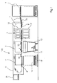
- FIG. 1 the basic structure of a sheet punching and embossing machine 100 for punching, breaking and depositing sheets of paper, cardboard and the like is shown.
- the punching and embossing machine 100 has a feeder 1, a punching station 2, a breaking station 3 and a boom 4, which are supported and enclosed by a common machine housing 5.
- the sheets 6 are separated by a feeder 1 from a stack and fed and gripped by mounted on revolving chains 7 rapiers 8 at its front edge and intermittently pulled through the various stations 2, 3 and 4 of the punching and embossing machine 100 therethrough.
- the punching station 2 consists of a lower table 9 and an upper table 10.
- the lower table 9 is fixedly mounted in the machine frame and provided with a counter plate to the punching knife.
- the upper table 10 is supported vertically movable back and forth.
- the gripper bar 8 transports the sheet 6 from the punching and embossing station 2 in the subsequent Ausbrechstation 3, which is equipped with breakout tools.
- the breaking station 3 the unwanted pieces of waste are pushed out of the sheet 6 downwards with the aid of the stripping tools, whereby the waste pieces 11 fall into a container-like carriage 12 inserted below the station.
- the boom 4 may also include a pallet 13 on which the individual sheets are stacked in the form of a stack 14, so that after reaching a certain stack height, the pallets stacked with the Bows 14 can be moved away from the area of the punching and embossing machine 100.
- the chains 7 carry a plurality of gripper bars 8, for example. Here are 8, so that multiple sheets 6 can be processed simultaneously in the various stations 2, 3 and 4.
- the sheet punching and embossing machine has a machine control 15 with control panel and display.
- this controller 15 By this controller 15 and the Bogenbrems- and -strreckvorraum is driven.
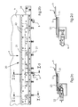
- a pneumatic sheet braking and stretching device 20 is shown.
- the mounting plate 24, which is part of the Bogenbrems- and -recking device 20 has holes for screwing the device with the tool frame of the processing stations 3, 4 of the sheet punching and embossing machine 100.
- the sheet brake and -stretching device 20 has two ports, a port A, via which the vacuum generator 22 can be acted upon with a blown air b, and a port B of the device for cleaning the Bogenbrems- and -stretching device 20, which can also be acted upon with a blown air b.
- An arc 6, which is to be braked and stretched by the Bogenbrems- and -strreckvortechnisch 20 is for Veranschlauichung the sheet position relative to Bogenbrems- and -strreckvortechnisch 20 in Fig. 2a and 2 B shown. For clarity, grab lines 8 were not shown.
- Fig. 2b is the air flow through the Saugluftkanalsystem 23 and the suction openings 21 indicated by arrows.
- the Saug povertykanalsystem 23 serves to connect the suction openings 21 with the vacuum generators 22 and is in the sectional views Fig. 2c and Fig. 2d represented by the Bogenbrems- and stretching device.
- the connection A of the vacuum generator 22 is acted upon by a blown air b.
- the blown air b flows through the vacuum generator 22, whereby a negative pressure is generated due to the Venturi effect, which is provided via the Saugluftkanalsystem 23 at the suction ports 21. Due to the negative pressure, air is sucked into the suction openings 21 and this suction air s sucks a sheet 6 moved over it and brakes it.
- Fig. 3a shows the Bogenbrems- and stretching device 20 with the air guide in cleaning the device.
- the Bogenbrems- and stretching device 20 is then cleaned when the punching and embossing machine 100 is not in operation, so if no sheet 6 is to be braked.
- the connection B of the device for cleaning the Bogenbrems- and -stretching device 20 is acted upon by a blown air b. Via a channel 25, the blowing air b is passed into the Saugluftkanalsystem 23, blows this and thereby removes dust and dirt particles. The blowing air escapes through the suction openings 21.
- the port B of the device for cleaning the Bogenbrems- and -strreckvorides 20 and the terminal A of the vacuum generator 22 can be acted upon simultaneously with a blown air b (in Fig. 3a not shown).
- vacuum generator, Saugluftkanalsystem and suction openings of a blast air b flows through and cleaned.
- the connection of the terminal B of the device for cleaning the Bogenbrems- and -strreckvortechnisch 20 to the Saugluftkanalsystem 23 is in the sectional view Fig. 3b
- a channel 25 connects port B and suction ports 21.
Description
Die Erfindung betrifft eine Bogenbearbeitungsmaschine mit Bogenbrems- und streckvorrichtung gemäß dem Oberbegriff von Anspruch 1 und ein Verfahren zur Reinigung derselben gemäß dem Oberbegriff von Anspruch 4.The invention relates to a sheet-processing machine with Bogenbrems- and stretching device according to the preamble of
Bogenbearbeitende Maschinen besitzen gewöhnlich einen Anleger, Bearbeitungsstationen und einen Ausleger. Bei der Bogen bearbeitenden Maschine kann es sich beispielsweise um Bogendruckmaschinen oder insbesondere Weiterverarbeitungsmaschinen wie Bogenstanz- und -prägemaschinen handeln. Von einem im Anleger befindlichen Bogenstapel wird ein zuoberst liegender Bogen vereinzelt und an ein Transportsystem übergeben. Das Transportsystem transportiert den Bogen durch die Bearbeitungsstation bis zur Auslage. Ein bekanntes Transportsystem bei Bogenstanz- und Prägemaschinen sind beispielsweise umlaufende Greiferwagen. Diese bestehen jeweils aus einer Querstange, an der Greifer angebracht sind, mit welchen der Bogen an seinem Vorderrand ergriffen wird und deren Enden an einem seitlichen Kettenzug befestigt sind, der die Greiferwagen durch die Maschine führt.
Im Auslegerbereich von Bogendruckmaschinen kommen ebenfalls Greiferwagen zur Bogenführung zum Einsatz, während die Bogen durch die Druckwerke mittels Trommeln mit Zangengreifersystem geführt werden.
Zur Auslage von Bogen in Bogen bearbeitenden Maschinen und beispielsweise zur Bearbeitung in Weiterverarbeitungsmaschinen muss der Bogen bis zum Stillstand abgebremst werden. Dies geschieht zum einen durch Abbremsen der Greiferwagen als auch zusätzlich durch Bogenbremsen.Sheet processing machines usually have a feeder, work stations, and a boom. The sheet-processing machine may be, for example, sheet-fed presses or, in particular, further-processing machines, such as sheet punching and embossing machines. From a stack of sheets in the feeder, an uppermost sheet is separated and transferred to a transport system. The transport system transports the sheet through the processing station to the delivery. A well-known transport system in sheet punching and embossing machines are, for example, rotating gripper carriage. These each consist of a cross bar, are attached to the gripper, with which the sheet is gripped at its front edge and the ends are attached to a lateral chain hoist, which guides the gripper carriage through the machine.
In the delivery area of sheet-fed presses, gripper carriages are also used for sheet guiding, while the sheets are guided through the printing units by means of drums with gripper gripping system.
For the delivery of sheets in sheet processing machines and, for example, for processing in further processing machines, the sheet must be braked to a standstill. This happens on the one hand by braking the gripper carriage and also by sheet brakes.
Als Stanzen wird das Schneiden mit in sich geschlossenen geometrischen Zuschnittsformen bezeichnet, die kreisförmig, oval oder mehreckig sowie Phantasieformen aller Art sein können. Auch die in der Druckweiterverarbeitung geübten Praktiken, wie Stanzen mit Locheisen, Eckenabstoßen und Registerstanzen werden zu diesem Bereich gezählt. Die Stanzung erfolgt gegen eine Stanzunterlage oder gegen Stempel, teilweise sind es auch Schervorgänge (vg. Druckweiterverarbeitung, Ausbildungsleitfaden für
Eine derartige Flachbettstanze ist beispielsweise aus der
Sowohl in der Ausbrechstation als auch in der Nutzentrennstation mit Bogenauslage muss der Bogen von der Transportgeschwindigkeit bis zum Stillstand abgebremst werden. Da der vom vorhergehenden Zuschnitt geschwächte Bogen mit hoher Geschwindigkeit in den Stationen eintrifft, kann die alleinige Verlangsamung der vorderen Greiferstange ein Aufschieben seines hinteren Teils hervorrufen. Dies soll durch zusätzliche Bremsvorrichtungen, welche auf die Fläche des Bogens wirken, verhindert werden. Der gestraffte Bogen kann mit höherer Genauigkeit bearbeitet und besser abgelegt werden.Both in the stripping station and in the blanking station with sheet delivery, the sheet must be braked from transport speed to standstill. Since the weakened from the previous blank sheet arrives at high speed in the stations, the sole deceleration of the front gripper bar can cause a postponement of its rear part. This should be done by additional Braking devices, which act on the surface of the sheet can be prevented. The streamlined sheet can be edited with higher accuracy and stored better.
Aus dem Stand der Technik sind zwei verschiedene Bogenbremsvorrichtungstypen bekannt. Die
In einer alternativen Lösung zu dieser mechanischen Bogenbremse kommen pneumatische Bogenbremsen zum Einsatz, wie z.B. aus der
Die notwendige Reinigung der pneumatischen Bogenbremse geschieht nach dem Stand der Technik durch manuelles Reinigen mit Pinsel, Bürsten, Streifen und / oder Druckluftpistolen. Um die Reinigung von Bogenbremsen zu beschleunigen und zu vereinfachen, wurde zum einen die Formgebung von Kanälen, Unterdruckkammern und Düsen optimiert, als auch die Demontage der einzelnen Komponenten der Bogenbremse vereinfacht, wie z. B. in der
Um die Funktionalität der Bremse trotz Verschmutzung zu gewährleisten, kann die Transport- und damit die Bearbeitungsgeschwindigkeit der Bogenbearbeitenden Maschine reduziert werden. Dies hat eine geringere Produktivität zur Folge. Soll die Geschwindigkeit nicht weiter verringert werden, oder ist die volle Funktionalität der Bremse trotz reduzierter Geschwindigkeit aufgrund von sehr starker Verschmutzung nicht mehr gewährleistet, muss die Bogenbremse gereinigt werden. Da die Reinigung bei Maschinenstillstand geschehen muss, wird die Produktivität hierdurch beträchtlich verringert.To ensure the functionality of the brake despite contamination, the transport and thus the processing speed of the sheet-processing machine can be reduced. This results in lower productivity. If the speed is not further reduced, or the full functionality of the brake despite reduced speed due to very heavy pollution is no longer guaranteed, the sheet brake must be cleaned. Since the cleaning must be done in machine downtime, thereby productivity is considerably reduced.
Aufgabe der vorliegenden Erfindung ist es nun, eine markierungsfreie Bogenbremse zu schaffen, welche eine höhere Maschinenproduktivität ermöglicht durch eine Reduzierung der Maschinenstillstandzeiten aufgrund von Bogenbremsenreinigung. Gelöst wird diese Aufgabe durch eine pneumatische Bogenbremse mit den Merkmalen von Anspruch 1 und ein Verfahren zur Reinigung einer solchen Bogenbremse nach Anspruch 4.Object of the present invention is therefore to provide a mark-free sheet brake, which allows a higher machine productivity by reducing the machine downtime due to sheet brake cleaning. This object is achieved by a pneumatic sheet brake with the features of
Eine erfindungsgemäße Bogenbearbeitungsmaschine besitzt mindestens eine Bearbeitungsstation. Bei einer Bogenstanz- und -prägemaschine sind beispielsweise mindestens eine Stanzstation und Prägestation, Ausbrechstation und Nutzentrennstation vorhanden. Durch einen Bogenanleger werden die Bogen vereinzelt und dem Transportsystem zugeführt, welches die Bogen durch die Maschine transportiert. Das Transportsystem kann als umlaufendes Kettensystem ausgebildet sein, durch das Greiferstangen geführt werden. Die Greiferstangen besitzen Greifer, welche die Bogen an ihrer Vorderkante ergreifen und somit durch die Maschine ziehen. Um den Bogen in den Bearbeitungsstationen besser abbremsen und in gestrecktem Zustand bearbeiten zu können, befinden sich im Einlaufbereich der Stationen pneumatische Bogenbrems- und - streckvorrichtungen. In Ausbrechstation und Nutzentrennstation sind die Vorrichtungen direkt in den Werkzeug- oder Gegenwerkzeugrahmen eingelassen. Dadurch befinden sich die Vorrichtungen in einer Ebene parallel und in minimalem Abstand zur Ebene, in welcher die Bogen von der Fördereinrichtung durch die Bearbeitungsstationen transportiert werden, einer so genannten Bogenförderebene.An inventive sheet processing machine has at least one processing station. In a sheet punching and embossing machine, for example, at least one stamping station and stamping station, breaking station and blanking station are present. By a sheet feeder, the sheets are separated and fed to the transport system, which transports the sheets through the machine. The transport system can be designed as a circulating chain system, are guided by the gripper bars. The gripper bars have grippers which grasp the sheets at their leading edge and thus pull through the machine. In order to better brake the sheet in the processing stations and to be able to work in the stretched state, pneumatic sheet braking and stretching devices are located in the inlet area of the stations. In stripping station and depaneling station, the devices are embedded directly in the tool or counter tool frame. As a result, the devices are in a plane parallel and at a minimum distance from the plane in which the sheets are transported by the conveyor through the processing stations, a so-called sheet conveying plane.
Auch im Ausleger befindet sich eine Bogenbremsvorrichtung in einer Ebene parallel und in unmittelbarer Nähe zur Bogenförderebene. Da die Greifer den Bogen in dieser Station freigeben, ist es besonders notwendig, den Bogen zusätzlich abzubremsen.Also in the boom is a sheet braking device in a plane parallel and in close proximity to the sheet conveying plane. Since the grippers release the bow in this station, it is particularly necessary to additionally decelerate the bow.
In der Bogenbrems- und -streckvorrichtung befinden sich Saugöffnungen. Die Bogen werden von dem Transportsystem direkt über die Saugöffnungen hinweg bewegt. Wenn an den Saugöffnungen ein Unterdruck herrscht, werden die sich darüber hinweg bewegenden Bogen angesaugt, dadurch abgebremst und gleichzeitig gestreckt.There are suction holes in the sheet braking and stretching device. The sheets are moved by the transport system directly over the suction openings. If a vacuum prevails at the suction openings, the sheets moving over them are sucked in, thereby braked and at the same time stretched.
Um an den Saugöffnungen einen Unterdruck bereitzustellen, werden nach dem Venturi-Prinzip arbeitende Unterdruckerzeuger über einen Anschluss A mit Blasluft beaufschlagt und der erzeugte Unterdruck wird über ein Saugluftkanalsystem an die Saugöffnungen übertragen. Um Unterdruckerzeuger, Saugluftkanalsystem und Saugöffnungen einfach und schnell reinigen zu können, besitzt die Bogenbrems- und streckvorrichtung eine Reinigungseinrichtung. Diese besitzt in vorteilhafter Weise mindestens einen Anschluss B, der mit Blasluft beaufschlagt werden kann und der in Verbindung steht mit dem Saugluftkanalsystem der Bogenbrems- und -straffvorrichtung und damit mittelbar mit den Saugöffnungen und den Unterdruckerzeugern.In order to provide a negative pressure at the suction openings, working under the Venturi principle vacuum generator via a port A with blowing air and the negative pressure generated is transmitted via a Saugluftkanalsystem to the suction ports. In order to clean vacuum generator, Saugluftkanalsystem and suction openings easily and quickly, the Bogenbrems- and stretching device has a cleaning device. This has advantageously at least one port B, which can be acted upon with blown air and which is in communication with the Saugluftkanalsystem the Bogenbrems- and -straffvorrichtung and thus indirectly with the suction openings and the vacuum generators.
Soll die Bogenbrems- und -streckvorrichtung von Staub gereinigt werden, so wird der Anschluss B der Einrichtung zur Reinigung der Bogenbrems- und streckvorrichtung mit Blasluft beaufschlagt. Mittels Kanälen wird die Blasluft in das Saugluftkanalsystem und durch die Saugöffnungen geblasen und löst dabei Schmutzpartikel und transportiert diese nach außen. Konstruktionsbedingt werden dabei die Unterdruckerzeuger kaum gereinigt.If the sheet braking and stretching device to be cleaned of dust, the port B of the device for cleaning the sheet braking and stretching device is acted upon with blowing air. By means of ducts, the blown air is blown into the suction air duct system and through the suction openings, thereby dissolving dirt particles and transporting them outwards. Due to the design, the vacuum generators are hardly cleaned.
Deshalb wird in einem alternativen Verfahren Anschluss A der Unterdruckerzeuger und Anschluss B der Einrichtung zur Reinigung der Bogenbrems- und -streckvorrichtung gleichzeitig mit Blasluft beaufschlagt.Therefore, in an alternative method, port A of the vacuum generator and port B of the device for cleaning the Bogenbrems- and -stretching device simultaneously subjected to blowing air.
Besonders vorteilhaft ist es, diese beiden Verfahren in der beschriebenen Weise nacheinander durchzuführen. Dadurch wird der Reinigungseffekt verstärkt.It is particularly advantageous to carry out these two processes in succession in the manner described. This enhances the cleaning effect.
In einer vorteilhaften Ausführungsform der Bogenbearbeitenden Maschine besitzt diese eine Steuerung, in welcher die oben beschriebenen Verfahren als Reinigungsprogramme hinterlegt sind und durch welche die Einrichtung zur Reinigung der Bogenbrems- und - straffvorrichtung aktiviert, d. h., die Beaufschlagung der Anschlüsse mit Blasluft geregelt werden kann. Die Aktivierung erfolgt praktischer Weise automatisch bei jedem Maschinenstillstand, wozu ein Kurz-Reinigungsprogramm mit einer Dauer von mehreren Sekunden in der Steuerung hinterlegt ist. Ein weiteres hinterlegtes mehrminütiges Reinigungsprogramm, welches manuell aktiviert werden kann, dient einer Intensivreinigung der Vorrichtung.
Hinsichtlich weiterer vorteilhafter Ausgestaltungen der Erfindung wird auf die Unteransprüche sowie die Beschreibung eines Ausführungsbeispiels unter Bezugnahme auf die beiliegenden Zeichnungen verwiesen.In an advantageous embodiment of the sheet-processing machine this has a control in which the above-described methods are deposited as cleaning programs and by which the means for cleaning the Bogenbrems- and - tightening device activated, ie, the admission of the connections can be controlled with blown air. Activation is carried out automatically at each machine standstill, for which a short cleaning program with a duration of several seconds is stored in the control. Another deposited multi-minute Cleaning program, which can be activated manually, is used for intensive cleaning of the device.
With regard to further advantageous embodiments of the invention, reference is made to the dependent claims and the description of an embodiment with reference to the accompanying drawings.
Die Erfindung soll an Hand eines Ausführungsbeispiels noch näher erläutert werden. Es zeigen in schematischer Darstellung
- Fig. 1
- eine erfindungsgemäße Bogenbearbeitungsmaschine
- Fig. 2a
- eine Ansicht einer pneumatischen Bogenbrems- und -streckvorrichtung
- Fig. 2b
- eine Draufsicht einer pneumatischen Bogenbrems- und -streckvorrichtung mit Luftführung im Betrieb
- Fig. 2c
- eine Detailansicht im Bereich eines Unterdruckerzeugers als Schnittdarstellung entlang IIc-IIc in
Fig. 2b - Fig. 2d
- eine Detailansicht im Bereich des Anschlusses A als Schnittdarstellung entlang IId-IId in
Fig. 2b - Fig. 3a
- eine Draufsicht einer pneumatischen Bogenbrems- und -streckvorrichtung mit Luftführung bei Reinigung
- Fig. 3b
- eine Detailansicht im Bereich des Anschlusses B als Schnittdarstellung entlang IIIb-IIIb in
Fig. 3a
- Fig. 1
- an inventive sheet processing machine
- Fig. 2a
- a view of a pneumatic Bogenbrems- and stretching device
- Fig. 2b
- a plan view of a pneumatic Bogenbrems- and -strreckvorrichtung with air duct in operation
- Fig. 2c
- a detailed view in the region of a vacuum generator as a sectional view along IIc-IIc in
Fig. 2b - Fig. 2d
- a detailed view in the region of the terminal A as a sectional view along IId-IId in
Fig. 2b - Fig. 3a
- a plan view of a pneumatic Bogenbrems- and -strreckvorrichtung with air guide during cleaning
- Fig. 3b
- a detailed view in the region of the terminal B as a sectional view along IIIb-IIIb in
Fig. 3a
In
Die Bögen 6 werden durch einen Anleger 1 von einem Stapel vereinzelt und zugeführt und von auf umlaufenden Ketten 7 befestigten Greiferstangen 8 an ihrer Vorderkante ergriffen und intermittierend durch die verschiedenen Stationen 2, 3 und 4 der Stanz- und Prägemaschine 100 hindurch gezogen.The
Die Stanzstation 2 besteht aus einem Untertisch 9 und einem Obertisch 10. Der Untertisch 9 ist fest im Maschinengestell gelagert und mit einer Gegenplatte zum Stanzmesser versehen. Der Obertisch 10 ist vertikal hin- und her bewegbar gelagert.The punching
Die Greiferstange 8 transportiert den Bogen 6 von der Stanz- und Prägestation 2 in die nachfolgende Ausbrechstation 3, die mit Ausbrechwerkzeugen ausgestattet ist. In der Ausbrechstation 3 werden mit Hilfe der Ausbrechwerkzeuge die nicht benötigten Abfallstücke aus dem Bogen 6 nach unten herausgestoßen, wodurch die Abfallstücke 11 in einen unter der Station eingeschobenen behälterartigen Wagen 12 fallen. Im Einlaufbereich der Ausbrechstation 3 befindet sich eine Bogenbrems- und -straffvorrichtung 20.The
Von der Ausbrechstation 3 gelangt der Bogen in den Ausleger 4, wo der Bogen entweder nur einfach abgelegt wird, oder aber gleichzeitig eine Trennung der einzelnen Nutzen erfolgt. Im Einlaufbereich des Auslegers 4 befindet sich eine Bogenbrems- und - straffvorrichtung 20. Der Ausleger 4 kann auch eine Palette 13 enthalten, auf der die einzelnen Bögen in Form eines Stapels 14 aufgestapelt werden, so dass nach Erreichen einer bestimmten Stapelhöhe die Paletten mit den aufgestapelten Bögen 14 aus dem Bereich der Stanz- und Prägemaschine 100 weggefahren werden können.From the stripping station 3, the sheet enters the
Wie zu erkennen ist, tragen die Ketten 7 mehrere Greiferstangen 8, bspw. sind es hier 8, so dass mehrere Bögen 6 gleichzeitig in den verschiedenen Stationen 2, 3 und 4 bearbeitet werden können.As can be seen, the chains 7 carry a plurality of
Zu ihrer Bedienung und Steuerung besitzt die Bogenstanz- und -prägemaschine eine Maschinensteuerung 15 mit Bedienpult und Anzeige. Durch diese Steuerung 15 wird auch die Bogenbrems- und -streckvorrichtung angesteuert.For their operation and control, the sheet punching and embossing machine has a machine control 15 with control panel and display. By this controller 15 and the Bogenbrems- and -strreckvorrichtung is driven.
In
Ein Bogen 6, welcher durch die Bogenbrems- und -streckvorrichtung 20 gebremst und gestreckt werden soll, ist zur Veranschlaulichung der Bogenposition relativ zur Bogenbrems- und -streckvorrichtung 20 in
In
- 11
- Anlegerinvestor
- 22
- Stanzstationpunching station
- 33
- Ausbrechstationstripping
- 44
- Auslegerboom
- 55
- Maschinengehäusemachine housing
- 66
- Bogenbow
- 77
- Transportsystem (Ketten)Transport system (chains)
- 88th
- Greiferstangengripper bars
- 99
- Untertischunder table
- 1010
- Obertischovertable
- 1111
- Abfallstücketrimmings
- 1212
- Wagendare
- 1313
- Palettepalette
- 1414
- Auslagestapeldelivery pile
- 1515
- Steuerungcontrol
- 1616
- Zuführtischfeed
- 2020
- Bogenbrems- und -streckvorrichtungSheet braking and stretching device
- 2121
- Saugöffnungsuction opening
- 2222
- UnterdruckerzeugerVacuum generator
- 2323
- SaugluftkanalsystemSaugluftkanalsystem
- 2424
- Befestigungsblechmounting plate
- 2525
- Kanalchannel
- 100100
- Bogenstanz- und -prägemaschineSheet punching and embossing machine
- AA
- Anschluss der UnterdruckerzeugerConnection of the vacuum generator
- BB
- Anschluss der Einrichtung zur Reinigung der Bogenbrems- und -streckvorrichtungConnection of the device for cleaning the Bogenbrems- and -strreckvorrichtung
- ss
- Saugluftsuction
- bb
- Blasluftblowing air
- FF
- Förderrichtungconveying direction
Claims (5)
- Sheet-processing machine, in particular sheet-fed diecutting and stamping/embossing machine (100) including at least one processing station (2, 3) and a delivery (4), a transport system (7) for guiding sheets and a pneumatic sheet-braking and tautening device (20) located in the delivery (4) and/or in a processing station (2, 3) and arranged in a plane parallel to and in the immediate vicinity of the sheet conveying plane and having suction openings (21) directed towards the sheet conveying plane, wherein negative pressure is present at the suction openings, the negative pressure generated by negative-pressure sources (22) to which blown air (b) is applied via at least one connection (A), and wherein the negative pressure is transmitted to the suction openings (21) by a suction channel system (23),
characterized in
that the sheet-braking and tautening device (20) includes a device for cleaning the former, equipped with at least one connection (B) to which blown air (b) can be supplied and which is connected to the suction air channel system (23) of the sheet-braking and tautening device (20) for blowing through the suction air channel system (23) and the suction openings (21). - Sheet-processing machine according to Claim 1,
characterized in
that the sheet-processing machine includes a control (15) for activating the device for cleaning the sheet-braking and tautening device (20). - Method for cleaning a pneumatic sheet-braking and tautening device (20) in a sheet-processing machine according to Claim 1, characterized by the step of blowing air through the suction-air channel system (23) and the suction openings (21) by supplying blown air (b) to a connection (B) of the device for cleaning the sheet-braking and tautening device (20).
- Method for cleaning a pneumatic sheet-braking and tautening device (20) of a sheet-processing machine according to Claim 1, characterized by the step of blowing air through the suction-air channel system (23), the suction openings (21), and the negative-pressure sources (22) by simultaneous application of blown air (b) to the at least one connection (A) of the negative-pressure sources (22) and to the connection (B) of the device for cleaning the sheet-braking and tautening device (20).
- Method for cleaning a pneumatic sheet-braking and tautening device (20) of a sheet-processing machine according to Claim 1, characterized by the steps ofa) cleaning according to Claim 4b) cleaning according to Claim 5
Applications Claiming Priority (1)
| Application Number | Priority Date | Filing Date | Title |
|---|---|---|---|
| DE102006059768 | 2006-12-18 |
Publications (3)
| Publication Number | Publication Date |
|---|---|
| EP1935820A2 EP1935820A2 (en) | 2008-06-25 |
| EP1935820A3 EP1935820A3 (en) | 2011-07-06 |
| EP1935820B1 true EP1935820B1 (en) | 2014-04-16 |
Family
ID=39212210
Family Applications (1)
| Application Number | Title | Priority Date | Filing Date |
|---|---|---|---|
| EP07121391.2A Active EP1935820B1 (en) | 2006-12-18 | 2007-11-23 | Sheet processing machine with sheet brake device and method for cleaning a sheet brake device |
Country Status (1)
| Country | Link |
|---|---|
| EP (1) | EP1935820B1 (en) |
Cited By (1)
| Publication number | Priority date | Publication date | Assignee | Title |
|---|---|---|---|---|
| CN108367876A (en) * | 2015-10-13 | 2018-08-03 | 鲍勃斯脱梅克斯股份有限公司 | Device and method for handling of paper element |
Families Citing this family (5)
| Publication number | Priority date | Publication date | Assignee | Title |
|---|---|---|---|---|
| PL2585258T3 (en) * | 2010-06-23 | 2020-11-16 | Bobst Mex Sa | Supporting device for a workstation of a profiling machine |
| US9193554B2 (en) | 2012-05-03 | 2015-11-24 | Bobst Mex Sa | Braking device for a flat element in sheet form and method for cleaning such a device |
| DE102013017400B4 (en) * | 2013-10-18 | 2015-05-28 | Thomas Bühl | Two-part cleaning and polishing punch |
| WO2020245116A1 (en) * | 2019-06-05 | 2020-12-10 | Bobst Mex Sa | Suction brake, sheet conveyor with such suction brake and method of applying a retardation force to a moving sheet of material |
| JP2023551573A (en) * | 2020-12-10 | 2023-12-08 | ボブスト メックス ソシエテ アノニム | Positioning devices and assemblies for holding flat flexible elements and sheet material processing machines |
Citations (1)
| Publication number | Priority date | Publication date | Assignee | Title |
|---|---|---|---|---|
| US3779545A (en) * | 1971-07-14 | 1973-12-18 | Roland Offsetmaschf | Delivery arrangement |
Family Cites Families (1)
| Publication number | Priority date | Publication date | Assignee | Title |
|---|---|---|---|---|
| DE2453753C3 (en) * | 1974-11-13 | 1982-05-27 | M.A.N.- Roland Druckmaschinen AG, 6050 Offenbach | Sheet brake |
-
2007
- 2007-11-23 EP EP07121391.2A patent/EP1935820B1/en active Active
Patent Citations (1)
| Publication number | Priority date | Publication date | Assignee | Title |
|---|---|---|---|---|
| US3779545A (en) * | 1971-07-14 | 1973-12-18 | Roland Offsetmaschf | Delivery arrangement |
Cited By (1)
| Publication number | Priority date | Publication date | Assignee | Title |
|---|---|---|---|---|
| CN108367876A (en) * | 2015-10-13 | 2018-08-03 | 鲍勃斯脱梅克斯股份有限公司 | Device and method for handling of paper element |
Also Published As
| Publication number | Publication date |
|---|---|
| EP1935820A2 (en) | 2008-06-25 |
| EP1935820A3 (en) | 2011-07-06 |
Similar Documents
| Publication | Publication Date | Title |
|---|---|---|
| EP1882657B1 (en) | Braking system for sheets | |
| EP1867449B1 (en) | Waste fan for a sheet punch press and embossing machine | |
| EP2093176B1 (en) | Sheet braking device | |
| EP2452790B1 (en) | Processing station for a stamping machine and method for removing a test blank | |
| EP1935820B1 (en) | Sheet processing machine with sheet brake device and method for cleaning a sheet brake device | |
| DE102007022725A1 (en) | Bute braking system | |
| DE102016209347B4 (en) | Device for treating substrates | |
| DE102020124433B4 (en) | Feeder of a sheet-processing machine and method for supporting sheet separation in a feeder of a sheet-processing machine | |
| EP2653420B1 (en) | Method for sheet transfer and punching machine with gripper transport system | |
| DE102021131718B3 (en) | Punching tool carrier and method for changing punching tools | |
| WO2023148014A1 (en) | Processing machines and method for the relative orientation of a substrate to a processing unit in a processing machine | |
| EP1431011B1 (en) | Device for press-cutting and creasing | |
| DE202007012356U1 (en) | Bute braking system | |
| EP1970334A2 (en) | Soil cultivation machine with pneumatic transport device | |
| EP2366511B1 (en) | Separating device for detaching blanks with adjustable sheet braking device | |
| EP2602217B1 (en) | Sheet feeder with two suction wheels | |
| EP3013722B1 (en) | Method for adjusting at least one brake element of a sheet brake, and use of an unprinted section of a print substrate for decelerating the print substrate | |
| EP1916107A2 (en) | Device and method for finishing of sheet-like substrates in sheet-fed printing presses | |
| DE102007057457A1 (en) | Sheet handling system especially for stencil punching and embossing has a cleaning process to remove debris from retarding suction holes | |
| DE102020122815B4 (en) | Blowing device and feeder of a sheet processing machine with a blowing device | |
| DE102014013669A1 (en) | Punching machine with Greiferrandausstreifer | |
| DE102021131719B9 (en) | System comprising a processing machine and at least one lifting device and method for changing at least one punching tool | |
| EP4168338B1 (en) | Feeder unit of a sheet working or processing machine having a blasting device | |
| EP1925387B1 (en) | Flat-bed sheet punching press | |
| DE19756032A1 (en) | Separating and transporting paper sheets in printing presses |
Legal Events
| Date | Code | Title | Description |
|---|---|---|---|
| PUAI | Public reference made under article 153(3) epc to a published international application that has entered the european phase |
Free format text: ORIGINAL CODE: 0009012 |
|
| AK | Designated contracting states |
Kind code of ref document: A2 Designated state(s): AT BE BG CH CY CZ DE DK EE ES FI FR GB GR HU IE IS IT LI LT LU LV MC MT NL PL PT RO SE SI SK TR |
|
| AX | Request for extension of the european patent |
Extension state: AL BA HR MK RS |
|
| PUAL | Search report despatched |
Free format text: ORIGINAL CODE: 0009013 |
|
| AK | Designated contracting states |
Kind code of ref document: A3 Designated state(s): AT BE BG CH CY CZ DE DK EE ES FI FR GB GR HU IE IS IT LI LT LU LV MC MT NL PL PT RO SE SI SK TR |
|
| AX | Request for extension of the european patent |
Extension state: AL BA HR MK RS |
|
| 17P | Request for examination filed |
Effective date: 20120109 |
|
| AKX | Designation fees paid |
Designated state(s): AT BE BG CH CY CZ DE DK EE ES FI FR GB GR HU IE IS IT LI LT LU LV MC MT NL PL PT RO SE SI SK TR |
|
| REG | Reference to a national code |
Ref country code: DE Ref legal event code: R079 Ref document number: 502007012985 Country of ref document: DE Free format text: PREVIOUS MAIN CLASS: B65H0029680000 Ipc: B26D0007010000 |
|
| RIC1 | Information provided on ipc code assigned before grant |
Ipc: B26F 1/40 20060101ALI20131010BHEP Ipc: B26D 7/01 20060101AFI20131010BHEP Ipc: B26D 7/08 20060101ALI20131010BHEP Ipc: B65H 29/68 20060101ALI20131010BHEP |
|
| GRAP | Despatch of communication of intention to grant a patent |
Free format text: ORIGINAL CODE: EPIDOSNIGR1 |
|
| INTG | Intention to grant announced |
Effective date: 20131218 |
|
| GRAS | Grant fee paid |
Free format text: ORIGINAL CODE: EPIDOSNIGR3 |
|
| GRAA | (expected) grant |
Free format text: ORIGINAL CODE: 0009210 |
|
| AK | Designated contracting states |
Kind code of ref document: B1 Designated state(s): AT BE BG CH CY CZ DE DK EE ES FI FR GB GR HU IE IS IT LI LT LU LV MC MT NL PL PT RO SE SI SK TR |
|
| REG | Reference to a national code |
Ref country code: GB Ref legal event code: FG4D Free format text: NOT ENGLISH |
|
| REG | Reference to a national code |
Ref country code: CH Ref legal event code: EP |
|
| REG | Reference to a national code |
Ref country code: AT Ref legal event code: REF Ref document number: 662221 Country of ref document: AT Kind code of ref document: T Effective date: 20140515 |
|
| REG | Reference to a national code |
Ref country code: IE Ref legal event code: FG4D Free format text: LANGUAGE OF EP DOCUMENT: GERMAN |
|
| REG | Reference to a national code |
Ref country code: DE Ref legal event code: R096 Ref document number: 502007012985 Country of ref document: DE Effective date: 20140522 |
|
| REG | Reference to a national code |
Ref country code: NL Ref legal event code: VDEP Effective date: 20140416 |
|
| REG | Reference to a national code |
Ref country code: LT Ref legal event code: MG4D |
|
| PG25 | Lapsed in a contracting state [announced via postgrant information from national office to epo] |
Ref country code: GR Free format text: LAPSE BECAUSE OF FAILURE TO SUBMIT A TRANSLATION OF THE DESCRIPTION OR TO PAY THE FEE WITHIN THE PRESCRIBED TIME-LIMIT Effective date: 20140717 Ref country code: BG Free format text: LAPSE BECAUSE OF FAILURE TO SUBMIT A TRANSLATION OF THE DESCRIPTION OR TO PAY THE FEE WITHIN THE PRESCRIBED TIME-LIMIT Effective date: 20140716 Ref country code: FI Free format text: LAPSE BECAUSE OF FAILURE TO SUBMIT A TRANSLATION OF THE DESCRIPTION OR TO PAY THE FEE WITHIN THE PRESCRIBED TIME-LIMIT Effective date: 20140416 Ref country code: IS Free format text: LAPSE BECAUSE OF FAILURE TO SUBMIT A TRANSLATION OF THE DESCRIPTION OR TO PAY THE FEE WITHIN THE PRESCRIBED TIME-LIMIT Effective date: 20140816 Ref country code: LT Free format text: LAPSE BECAUSE OF FAILURE TO SUBMIT A TRANSLATION OF THE DESCRIPTION OR TO PAY THE FEE WITHIN THE PRESCRIBED TIME-LIMIT Effective date: 20140416 Ref country code: NL Free format text: LAPSE BECAUSE OF FAILURE TO SUBMIT A TRANSLATION OF THE DESCRIPTION OR TO PAY THE FEE WITHIN THE PRESCRIBED TIME-LIMIT Effective date: 20140416 Ref country code: CY Free format text: LAPSE BECAUSE OF FAILURE TO SUBMIT A TRANSLATION OF THE DESCRIPTION OR TO PAY THE FEE WITHIN THE PRESCRIBED TIME-LIMIT Effective date: 20140416 |
|
| PG25 | Lapsed in a contracting state [announced via postgrant information from national office to epo] |
Ref country code: SE Free format text: LAPSE BECAUSE OF FAILURE TO SUBMIT A TRANSLATION OF THE DESCRIPTION OR TO PAY THE FEE WITHIN THE PRESCRIBED TIME-LIMIT Effective date: 20140416 Ref country code: LV Free format text: LAPSE BECAUSE OF FAILURE TO SUBMIT A TRANSLATION OF THE DESCRIPTION OR TO PAY THE FEE WITHIN THE PRESCRIBED TIME-LIMIT Effective date: 20140416 Ref country code: ES Free format text: LAPSE BECAUSE OF FAILURE TO SUBMIT A TRANSLATION OF THE DESCRIPTION OR TO PAY THE FEE WITHIN THE PRESCRIBED TIME-LIMIT Effective date: 20140416 Ref country code: PL Free format text: LAPSE BECAUSE OF FAILURE TO SUBMIT A TRANSLATION OF THE DESCRIPTION OR TO PAY THE FEE WITHIN THE PRESCRIBED TIME-LIMIT Effective date: 20140416 |
|
| PG25 | Lapsed in a contracting state [announced via postgrant information from national office to epo] |
Ref country code: PT Free format text: LAPSE BECAUSE OF FAILURE TO SUBMIT A TRANSLATION OF THE DESCRIPTION OR TO PAY THE FEE WITHIN THE PRESCRIBED TIME-LIMIT Effective date: 20140818 |
|
| REG | Reference to a national code |
Ref country code: DE Ref legal event code: R097 Ref document number: 502007012985 Country of ref document: DE |
|
| PG25 | Lapsed in a contracting state [announced via postgrant information from national office to epo] |
Ref country code: CZ Free format text: LAPSE BECAUSE OF FAILURE TO SUBMIT A TRANSLATION OF THE DESCRIPTION OR TO PAY THE FEE WITHIN THE PRESCRIBED TIME-LIMIT Effective date: 20140416 Ref country code: SK Free format text: LAPSE BECAUSE OF FAILURE TO SUBMIT A TRANSLATION OF THE DESCRIPTION OR TO PAY THE FEE WITHIN THE PRESCRIBED TIME-LIMIT Effective date: 20140416 Ref country code: RO Free format text: LAPSE BECAUSE OF FAILURE TO SUBMIT A TRANSLATION OF THE DESCRIPTION OR TO PAY THE FEE WITHIN THE PRESCRIBED TIME-LIMIT Effective date: 20140416 Ref country code: DK Free format text: LAPSE BECAUSE OF FAILURE TO SUBMIT A TRANSLATION OF THE DESCRIPTION OR TO PAY THE FEE WITHIN THE PRESCRIBED TIME-LIMIT Effective date: 20140416 Ref country code: EE Free format text: LAPSE BECAUSE OF FAILURE TO SUBMIT A TRANSLATION OF THE DESCRIPTION OR TO PAY THE FEE WITHIN THE PRESCRIBED TIME-LIMIT Effective date: 20140416 |
|
| PLBE | No opposition filed within time limit |
Free format text: ORIGINAL CODE: 0009261 |
|
| STAA | Information on the status of an ep patent application or granted ep patent |
Free format text: STATUS: NO OPPOSITION FILED WITHIN TIME LIMIT |
|
| 26N | No opposition filed |
Effective date: 20150119 |
|
| PG25 | Lapsed in a contracting state [announced via postgrant information from national office to epo] |
Ref country code: IT Free format text: LAPSE BECAUSE OF FAILURE TO SUBMIT A TRANSLATION OF THE DESCRIPTION OR TO PAY THE FEE WITHIN THE PRESCRIBED TIME-LIMIT Effective date: 20140416 |
|
| REG | Reference to a national code |
Ref country code: DE Ref legal event code: R097 Ref document number: 502007012985 Country of ref document: DE Effective date: 20150119 |
|
| REG | Reference to a national code |
Ref country code: DE Ref legal event code: R081 Ref document number: 502007012985 Country of ref document: DE Owner name: MASTERWORK MACHINERY CO., LTD., CN Free format text: FORMER OWNER: HEIDELBERGER DRUCKMASCHINEN AG, 69115 HEIDELBERG, DE Effective date: 20150402 |
|
| PG25 | Lapsed in a contracting state [announced via postgrant information from national office to epo] |
Ref country code: BE Free format text: LAPSE BECAUSE OF NON-PAYMENT OF DUE FEES Effective date: 20141130 Ref country code: MC Free format text: LAPSE BECAUSE OF FAILURE TO SUBMIT A TRANSLATION OF THE DESCRIPTION OR TO PAY THE FEE WITHIN THE PRESCRIBED TIME-LIMIT Effective date: 20140416 Ref country code: LU Free format text: LAPSE BECAUSE OF FAILURE TO SUBMIT A TRANSLATION OF THE DESCRIPTION OR TO PAY THE FEE WITHIN THE PRESCRIBED TIME-LIMIT Effective date: 20141123 |
|
| REG | Reference to a national code |
Ref country code: CH Ref legal event code: NV Representative=s name: GLN S.A., CH Ref country code: CH Ref legal event code: PUE Owner name: MASTERWORK MACHINERY CO., LTD., CN Free format text: FORMER OWNER: HEIDELBERGER DRUCKMASCHINEN AG, DE |
|
| GBPC | Gb: european patent ceased through non-payment of renewal fee |
Effective date: 20141123 |
|
| PG25 | Lapsed in a contracting state [announced via postgrant information from national office to epo] |
Ref country code: SI Free format text: LAPSE BECAUSE OF FAILURE TO SUBMIT A TRANSLATION OF THE DESCRIPTION OR TO PAY THE FEE WITHIN THE PRESCRIBED TIME-LIMIT Effective date: 20140416 |
|
| REG | Reference to a national code |
Ref country code: IE Ref legal event code: MM4A |
|
| REG | Reference to a national code |
Ref country code: FR Ref legal event code: ST Effective date: 20150731 |
|
| PG25 | Lapsed in a contracting state [announced via postgrant information from national office to epo] |
Ref country code: GB Free format text: LAPSE BECAUSE OF NON-PAYMENT OF DUE FEES Effective date: 20141123 Ref country code: IE Free format text: LAPSE BECAUSE OF NON-PAYMENT OF DUE FEES Effective date: 20141123 |
|
| PG25 | Lapsed in a contracting state [announced via postgrant information from national office to epo] |
Ref country code: FR Free format text: LAPSE BECAUSE OF NON-PAYMENT OF DUE FEES Effective date: 20141201 |
|
| REG | Reference to a national code |
Ref country code: AT Ref legal event code: MM01 Ref document number: 662221 Country of ref document: AT Kind code of ref document: T Effective date: 20141123 |
|
| PG25 | Lapsed in a contracting state [announced via postgrant information from national office to epo] |
Ref country code: AT Free format text: LAPSE BECAUSE OF NON-PAYMENT OF DUE FEES Effective date: 20141123 |
|
| PG25 | Lapsed in a contracting state [announced via postgrant information from national office to epo] |
Ref country code: HU Free format text: LAPSE BECAUSE OF FAILURE TO SUBMIT A TRANSLATION OF THE DESCRIPTION OR TO PAY THE FEE WITHIN THE PRESCRIBED TIME-LIMIT; INVALID AB INITIO Effective date: 20071123 Ref country code: MT Free format text: LAPSE BECAUSE OF FAILURE TO SUBMIT A TRANSLATION OF THE DESCRIPTION OR TO PAY THE FEE WITHIN THE PRESCRIBED TIME-LIMIT Effective date: 20140416 Ref country code: TR Free format text: LAPSE BECAUSE OF FAILURE TO SUBMIT A TRANSLATION OF THE DESCRIPTION OR TO PAY THE FEE WITHIN THE PRESCRIBED TIME-LIMIT Effective date: 20140416 |
|
| REG | Reference to a national code |
Ref country code: CH Ref legal event code: PFA Owner name: MASTERWORK MACHINERY CO., LTD., CN Free format text: FORMER OWNER: MASTERWORK MACHINERY CO., LTD., CN |
|
| REG | Reference to a national code |
Ref country code: CH Ref legal event code: NV Representative=s name: BOVARD SA NEUCHATEL CONSEILS EN PROPRIETE INTE, CH |
|
| PGFP | Annual fee paid to national office [announced via postgrant information from national office to epo] |
Ref country code: CH Payment date: 20211130 Year of fee payment: 15 |
|
| REG | Reference to a national code |
Ref country code: CH Ref legal event code: PL |
|
| PG25 | Lapsed in a contracting state [announced via postgrant information from national office to epo] |
Ref country code: LI Free format text: LAPSE BECAUSE OF NON-PAYMENT OF DUE FEES Effective date: 20221130 Ref country code: CH Free format text: LAPSE BECAUSE OF NON-PAYMENT OF DUE FEES Effective date: 20221130 |
|
| PGFP | Annual fee paid to national office [announced via postgrant information from national office to epo] |
Ref country code: DE Payment date: 20231127 Year of fee payment: 17 |