EP1576265B1 - Abgasturbolader für eine brennkraftmaschine - Google Patents
Abgasturbolader für eine brennkraftmaschine Download PDFInfo
- Publication number
- EP1576265B1 EP1576265B1 EP03775381A EP03775381A EP1576265B1 EP 1576265 B1 EP1576265 B1 EP 1576265B1 EP 03775381 A EP03775381 A EP 03775381A EP 03775381 A EP03775381 A EP 03775381A EP 1576265 B1 EP1576265 B1 EP 1576265B1
- Authority
- EP
- European Patent Office
- Prior art keywords
- exhaust gas
- bypass
- turbine
- section
- turbocharger according
- Prior art date
- Legal status (The legal status is an assumption and is not a legal conclusion. Google has not performed a legal analysis and makes no representation as to the accuracy of the status listed.)
- Expired - Lifetime
Links
Images


Classifications
-
- F—MECHANICAL ENGINEERING; LIGHTING; HEATING; WEAPONS; BLASTING
- F01—MACHINES OR ENGINES IN GENERAL; ENGINE PLANTS IN GENERAL; STEAM ENGINES
- F01N—GAS-FLOW SILENCERS OR EXHAUST APPARATUS FOR MACHINES OR ENGINES IN GENERAL; GAS-FLOW SILENCERS OR EXHAUST APPARATUS FOR INTERNAL-COMBUSTION ENGINES
- F01N3/00—Exhaust or silencing apparatus having means for purifying, rendering innocuous, or otherwise treating exhaust
- F01N3/08—Exhaust or silencing apparatus having means for purifying, rendering innocuous, or otherwise treating exhaust for rendering innocuous
- F01N3/10—Exhaust or silencing apparatus having means for purifying, rendering innocuous, or otherwise treating exhaust for rendering innocuous by thermal or catalytic conversion of noxious components of exhaust
- F01N3/18—Exhaust or silencing apparatus having means for purifying, rendering innocuous, or otherwise treating exhaust for rendering innocuous by thermal or catalytic conversion of noxious components of exhaust characterised by methods of operation; Control
- F01N3/22—Control of additional air supply only, e.g. using by-passes or variable air pump drives
-
- F—MECHANICAL ENGINEERING; LIGHTING; HEATING; WEAPONS; BLASTING
- F01—MACHINES OR ENGINES IN GENERAL; ENGINE PLANTS IN GENERAL; STEAM ENGINES
- F01N—GAS-FLOW SILENCERS OR EXHAUST APPARATUS FOR MACHINES OR ENGINES IN GENERAL; GAS-FLOW SILENCERS OR EXHAUST APPARATUS FOR INTERNAL-COMBUSTION ENGINES
- F01N3/00—Exhaust or silencing apparatus having means for purifying, rendering innocuous, or otherwise treating exhaust
- F01N3/02—Exhaust or silencing apparatus having means for purifying, rendering innocuous, or otherwise treating exhaust for cooling, or for removing solid constituents of, exhaust
- F01N3/021—Exhaust or silencing apparatus having means for purifying, rendering innocuous, or otherwise treating exhaust for cooling, or for removing solid constituents of, exhaust by means of filters
- F01N3/033—Exhaust or silencing apparatus having means for purifying, rendering innocuous, or otherwise treating exhaust for cooling, or for removing solid constituents of, exhaust by means of filters in combination with other devices
- F01N3/035—Exhaust or silencing apparatus having means for purifying, rendering innocuous, or otherwise treating exhaust for cooling, or for removing solid constituents of, exhaust by means of filters in combination with other devices with catalytic reactors
-
- F—MECHANICAL ENGINEERING; LIGHTING; HEATING; WEAPONS; BLASTING
- F01—MACHINES OR ENGINES IN GENERAL; ENGINE PLANTS IN GENERAL; STEAM ENGINES
- F01N—GAS-FLOW SILENCERS OR EXHAUST APPARATUS FOR MACHINES OR ENGINES IN GENERAL; GAS-FLOW SILENCERS OR EXHAUST APPARATUS FOR INTERNAL-COMBUSTION ENGINES
- F01N3/00—Exhaust or silencing apparatus having means for purifying, rendering innocuous, or otherwise treating exhaust
- F01N3/08—Exhaust or silencing apparatus having means for purifying, rendering innocuous, or otherwise treating exhaust for rendering innocuous
- F01N3/10—Exhaust or silencing apparatus having means for purifying, rendering innocuous, or otherwise treating exhaust for rendering innocuous by thermal or catalytic conversion of noxious components of exhaust
- F01N3/18—Exhaust or silencing apparatus having means for purifying, rendering innocuous, or otherwise treating exhaust for rendering innocuous by thermal or catalytic conversion of noxious components of exhaust characterised by methods of operation; Control
- F01N3/22—Control of additional air supply only, e.g. using by-passes or variable air pump drives
- F01N3/222—Control of additional air supply only, e.g. using by-passes or variable air pump drives using electric valves only
-
- F—MECHANICAL ENGINEERING; LIGHTING; HEATING; WEAPONS; BLASTING
- F01—MACHINES OR ENGINES IN GENERAL; ENGINE PLANTS IN GENERAL; STEAM ENGINES
- F01N—GAS-FLOW SILENCERS OR EXHAUST APPARATUS FOR MACHINES OR ENGINES IN GENERAL; GAS-FLOW SILENCERS OR EXHAUST APPARATUS FOR INTERNAL-COMBUSTION ENGINES
- F01N3/00—Exhaust or silencing apparatus having means for purifying, rendering innocuous, or otherwise treating exhaust
- F01N3/08—Exhaust or silencing apparatus having means for purifying, rendering innocuous, or otherwise treating exhaust for rendering innocuous
- F01N3/10—Exhaust or silencing apparatus having means for purifying, rendering innocuous, or otherwise treating exhaust for rendering innocuous by thermal or catalytic conversion of noxious components of exhaust
- F01N3/18—Exhaust or silencing apparatus having means for purifying, rendering innocuous, or otherwise treating exhaust for rendering innocuous by thermal or catalytic conversion of noxious components of exhaust characterised by methods of operation; Control
- F01N3/22—Control of additional air supply only, e.g. using by-passes or variable air pump drives
- F01N3/225—Electric control of additional air supply
-
- F—MECHANICAL ENGINEERING; LIGHTING; HEATING; WEAPONS; BLASTING
- F01—MACHINES OR ENGINES IN GENERAL; ENGINE PLANTS IN GENERAL; STEAM ENGINES
- F01N—GAS-FLOW SILENCERS OR EXHAUST APPARATUS FOR MACHINES OR ENGINES IN GENERAL; GAS-FLOW SILENCERS OR EXHAUST APPARATUS FOR INTERNAL-COMBUSTION ENGINES
- F01N3/00—Exhaust or silencing apparatus having means for purifying, rendering innocuous, or otherwise treating exhaust
- F01N3/08—Exhaust or silencing apparatus having means for purifying, rendering innocuous, or otherwise treating exhaust for rendering innocuous
- F01N3/10—Exhaust or silencing apparatus having means for purifying, rendering innocuous, or otherwise treating exhaust for rendering innocuous by thermal or catalytic conversion of noxious components of exhaust
- F01N3/24—Exhaust or silencing apparatus having means for purifying, rendering innocuous, or otherwise treating exhaust for rendering innocuous by thermal or catalytic conversion of noxious components of exhaust characterised by constructional aspects of converting apparatus
- F01N3/30—Arrangements for supply of additional air
-
- F—MECHANICAL ENGINEERING; LIGHTING; HEATING; WEAPONS; BLASTING
- F02—COMBUSTION ENGINES; HOT-GAS OR COMBUSTION-PRODUCT ENGINE PLANTS
- F02B—INTERNAL-COMBUSTION PISTON ENGINES; COMBUSTION ENGINES IN GENERAL
- F02B37/00—Engines characterised by provision of pumps driven at least for part of the time by exhaust
- F02B37/12—Control of the pumps
- F02B37/18—Control of the pumps by bypassing exhaust from the inlet to the outlet of turbine or to the atmosphere
-
- F—MECHANICAL ENGINEERING; LIGHTING; HEATING; WEAPONS; BLASTING
- F02—COMBUSTION ENGINES; HOT-GAS OR COMBUSTION-PRODUCT ENGINE PLANTS
- F02B—INTERNAL-COMBUSTION PISTON ENGINES; COMBUSTION ENGINES IN GENERAL
- F02B37/00—Engines characterised by provision of pumps driven at least for part of the time by exhaust
- F02B37/12—Control of the pumps
- F02B37/24—Control of the pumps by using pumps or turbines with adjustable guide vanes
-
- F—MECHANICAL ENGINEERING; LIGHTING; HEATING; WEAPONS; BLASTING
- F02—COMBUSTION ENGINES; HOT-GAS OR COMBUSTION-PRODUCT ENGINE PLANTS
- F02M—SUPPLYING COMBUSTION ENGINES IN GENERAL WITH COMBUSTIBLE MIXTURES OR CONSTITUENTS THEREOF
- F02M26/00—Engine-pertinent apparatus for adding exhaust gases to combustion-air, main fuel or fuel-air mixture, e.g. by exhaust gas recirculation [EGR] systems
- F02M26/02—EGR systems specially adapted for supercharged engines
- F02M26/04—EGR systems specially adapted for supercharged engines with a single turbocharger
- F02M26/05—High pressure loops, i.e. wherein recirculated exhaust gas is taken out from the exhaust system upstream of the turbine and reintroduced into the intake system downstream of the compressor
-
- F—MECHANICAL ENGINEERING; LIGHTING; HEATING; WEAPONS; BLASTING
- F02—COMBUSTION ENGINES; HOT-GAS OR COMBUSTION-PRODUCT ENGINE PLANTS
- F02M—SUPPLYING COMBUSTION ENGINES IN GENERAL WITH COMBUSTIBLE MIXTURES OR CONSTITUENTS THEREOF
- F02M26/00—Engine-pertinent apparatus for adding exhaust gases to combustion-air, main fuel or fuel-air mixture, e.g. by exhaust gas recirculation [EGR] systems
- F02M26/02—EGR systems specially adapted for supercharged engines
- F02M26/09—Constructional details, e.g. structural combinations of EGR systems and supercharger systems; Arrangement of the EGR and supercharger systems with respect to the engine
- F02M26/10—Constructional details, e.g. structural combinations of EGR systems and supercharger systems; Arrangement of the EGR and supercharger systems with respect to the engine having means to increase the pressure difference between the exhaust and intake system, e.g. venturis, variable geometry turbines, check valves using pressure pulsations or throttles in the air intake or exhaust system
-
- F—MECHANICAL ENGINEERING; LIGHTING; HEATING; WEAPONS; BLASTING
- F02—COMBUSTION ENGINES; HOT-GAS OR COMBUSTION-PRODUCT ENGINE PLANTS
- F02B—INTERNAL-COMBUSTION PISTON ENGINES; COMBUSTION ENGINES IN GENERAL
- F02B29/00—Engines characterised by provision for charging or scavenging not provided for in groups F02B25/00, F02B27/00 or F02B33/00 - F02B39/00; Details thereof
- F02B29/04—Cooling of air intake supply
- F02B29/0406—Layout of the intake air cooling or coolant circuit
-
- F—MECHANICAL ENGINEERING; LIGHTING; HEATING; WEAPONS; BLASTING
- F02—COMBUSTION ENGINES; HOT-GAS OR COMBUSTION-PRODUCT ENGINE PLANTS
- F02M—SUPPLYING COMBUSTION ENGINES IN GENERAL WITH COMBUSTIBLE MIXTURES OR CONSTITUENTS THEREOF
- F02M26/00—Engine-pertinent apparatus for adding exhaust gases to combustion-air, main fuel or fuel-air mixture, e.g. by exhaust gas recirculation [EGR] systems
- F02M26/13—Arrangement or layout of EGR passages, e.g. in relation to specific engine parts or for incorporation of accessories
- F02M26/22—Arrangement or layout of EGR passages, e.g. in relation to specific engine parts or for incorporation of accessories with coolers in the recirculation passage
- F02M26/23—Layout, e.g. schematics
-
- Y—GENERAL TAGGING OF NEW TECHNOLOGICAL DEVELOPMENTS; GENERAL TAGGING OF CROSS-SECTIONAL TECHNOLOGIES SPANNING OVER SEVERAL SECTIONS OF THE IPC; TECHNICAL SUBJECTS COVERED BY FORMER USPC CROSS-REFERENCE ART COLLECTIONS [XRACs] AND DIGESTS
- Y02—TECHNOLOGIES OR APPLICATIONS FOR MITIGATION OR ADAPTATION AGAINST CLIMATE CHANGE
- Y02T—CLIMATE CHANGE MITIGATION TECHNOLOGIES RELATED TO TRANSPORTATION
- Y02T10/00—Road transport of goods or passengers
- Y02T10/10—Internal combustion engine [ICE] based vehicles
- Y02T10/12—Improving ICE efficiencies
Definitions
- the invention relates to an exhaust gas turbocharger for an internal combustion engine according to the preamble of claim 1.
- the publication DE 43 12 078 A1 describes a supercharged internal combustion engine with an exhaust gas turbine in the exhaust gas line and a compressor in the intake tract of the internal combustion engine.
- Aspirated combustion air is compressed to an increased charge pressure, below which the air is supplied to the cylinder of the internal combustion engine.
- the compressor is associated with an additional compressor, which rests on the same shaft as the main compressor and how it is driven by the exhaust gas turbine.
- About the auxiliary compressor recirculated exhaust gas from the exhaust line is first precompressed to an elevated pressure and then added to the intake from the main compressor air mass flow and fed into the intake.
- the additional compressor Due to the pre-compression of the exhaust gas in the additional compressor, the spectrum of operating conditions can be extended under which an exhaust gas recirculation can be performed.
- the additional compressor requires a relatively large design effort.
- US 4 611 465 discloses an exhaust gas turbocharger for a Internal combustion engine comprising a compressor in the intake tract and an exhaust gas turbine in the exhaust gas system.
- the exhaust gases of the internal combustion engine are a spiral-shaped exhaust gas collecting chamber, which is formed in the turbine housing, supplied, from which the exhaust gases are supplied to the turbine wheel.
- the exhaust gases flow via a turbine inlet cross section to the turbine wheel and drive it.
- the internal combustion engine described in US Pat. No. 4,611,465 has two cylinder banks, the exhaust gases of which are each fed to a turbine inlet duct of the exhaust gas turbine. From each turbine inlet duct branches off an exhaust gas bypass, wherein the two bypass lines open into a common line section, in which an adjustable, load-pressure-controlled bypass valve is arranged.
- the bypass line opens into the exhaust pipe downstream of the exhaust gas turbine.
- the bypass valve is placed in the open position as soon as the boost pressure in the intake tract downstream of the compressor exceeds a given limit value, whereupon exhaust gas, bypassing the turbine wheel, is introduced directly into the exhaust gas line.
- the exhaust bypass line extends outside of the turbine housing and also flows outside of the turbine housing in the exhaust pipe line downstream of the exhaust gas turbine. This bypass has the exclusive function of reducing or preventing overpressure. Further functions can not be realized.
- the invention is based on the problem with simple structural measures to design an exhaust gas turbocharger in such a way that on the original function of the compression of combustion air addition, a further use as a gas pump is possible.
- the exhaust gas turbine forms a pump for the gas delivery device.
- an exhaust gas bypass bridging the turbine inlet cross section and connecting an exhaust gas collecting space in the turbine upstream of the turbine wheel to an outlet region of the exhaust gas turbine is provided, into which a gas delivery line of the gas conveying device discharges. Due to the static pressure drop between the exhaust gas collecting space and the outlet region, a conveying effect is achieved, via which the gas located in the gas conveying line is sucked in and conveyed into the outlet region of the exhaust gas turbine.
- the exhaust gas turbine takes over the function of a pump for the gas conveyor.
- This pump function can be realized solely via the junction of the gas delivery line in the bypass to the turbine inlet cross section, through which the main mass flow of the exhaust gas from the exhaust line is supplied to the turbine wheel.
- the partial mass flow of the exhaust gas guided via the exhaust gas bypass is expediently not more than 5% of the total exhaust gas mass flow conducted through the exhaust gas turbine and is for example in the range between approximately 1% and 2%.
- the pump function can be improved by integrating into the exhaust gas bypass a nozzle with a tapered cross-section and the gas delivery line opens downstream of the narrowest nozzle cross-section in the bypass.
- a further pressure reduction is achieved, which can be used for an additional conveying effect for the gas delivery device.
- an ejector part around which the exhaust gas flows can be integrated into the bypass, the gas mass flow from the gas conveying device being introduced into the bypass via the ejector part.
- the ejector part has an orifice opening for the gas mass flow to be conveyed into the exhaust gas bypass.
- the bypass advantageously extends annularly around the turbine wheel, wherein distributed over the circumference of the bypass expediently a plurality of Ejektor former are arranged and in each case between two adjacent Ejektor former a narrowest nozzle cross-section is formed.
- the ejector parts can be designed identically, in particular identically or mirror-symmetrically, or according to a further advantageous embodiment also be contoured differently, such that the nozzle inlet cross-section lying between two adjacent ejector parts and the nozzle outlet cross-section cause differing flow directions for the passing gas. In this way additional fluidic effects can be generated.
- the ejector part is expediently an outlet channel for the gas delivery line, wherein the mouth channel runs approximately perpendicular to the inflow direction of the exhaust gas in the bypass.
- This embodiment allows a simple connection of the gas delivery line to the Ejektorteil.
- the mouth channel is connected via the orifice with the bypass, wherein the Mouth opening, for example, may be slit-shaped and the orientation of the mouth opening is approximately parallel to the orientation of the nozzle outlet cross-section, so that the gas entering the bypass has approximately the same flow direction as the exhaust gas flowing through the bypass.
- the fluidic entrainment effect is improved.
- the gas delivery device can be used as a pump, for example, for a crankcase ventilation device, are derived via the oily vent gases from the crankcase and subjected to cleaning.
- the exhaust gas turbine takes over the function of a pump for the vent gases and promotes - after passing through an oil separator - into the exhaust system.
- the gas delivery device forms a pump for an air injection device, via which additional ambient air can be supplied after the exhaust gas turbine wheel.
- the blown-in ambient air can be utilized in a downstream catalytic converter to support the catalyst function and / or a soot filter to support the burning process of the soot, whereby in particular the exhaust behavior can be improved after a cold start of the engine.
- the internal combustion engine 1 shown in FIG. 1 - an Otto engine or a diesel engine - is assigned an exhaust gas turbocharger 2 with an exhaust gas turbine 3 in the exhaust gas line 4 and a compressor 5 in the intake tract 6.
- the exhaust gas turbine 3 is driven by the pressurized exhaust gases of the internal combustion engine 1. Via a shaft 7, the compressor 5 is driven by the exhaust gas turbine 3, which sucks in ambient air and compressed to an increased charge pressure.
- the exhaust gas turbine 3 is variable with a variable turbine geometry 8 Adjustment of the effective turbine inlet cross-section equipped.
- a charge air cooler is arranged in the intake tract 6, into which the air previously compressed in the compressor 5 enters and is cooled. Downstream of the charge air cooler 9, the charge air is supplied under boost pressure to the cylinder inlets of the internal combustion engine 1.
- the internal combustion engine 1 is equipped with an exhaust gas recirculation device 10 which comprises a return line 11 between the exhaust line 4 upstream of the exhaust gas turbine 3 and the intake section 6 downstream of the intercooler 9.
- an adjustable return valve 12 and a radiator 13 is integrated.
- a catalyst 15 is arranged for the catalytic purification of the exhaust gases to be discharged.
- the catalytic converter 15 may be preceded by a soot filter 16 - in the case of a diesel engine - to be filtered out via the soot particles and possibly burned off.
- the internal combustion engine 1 is equipped with a crankcase ventilation device 17, which comprises a gas delivery line 18 between the crankcase of the internal combustion engine and the exhaust gas turbine 3.
- a check valve 19 which opens in the direction of the exhaust gas turbocharger 3 and prevents unwanted backflow back into the crankcase.
- the valve 19 may also be designed as an actively adjustable valve.
- the internal combustion engine 1 is also associated with a Heileinblase worn 20, via the fresh air from the environment sucked and fed via the exhaust gas turbine 3 to the catalyst 15 and the soot filter 16 to support the catalyst function, in particular after a cold start of the internal combustion engine and the Rußabbangled in the soot filter.
- the Heileinblase listening 20 includes a gas delivery line 21, via which the combustion air is sucked from the atmosphere and in which an adjustable valve 23 is located.
- the gas delivery line 21 of the Heileinblase sexual 20 opens with the gas delivery line 18 of the crankcase ventilation device 17 in a common line section 22 which is guided in the exhaust gas turbine 3.
- control and control unit 14 all adjustable units of the internal combustion engine in dependence on state and operating variables are set. This relates in particular to the return valve 12 in the exhaust gas recirculation device 10, the variable turbine geometry 8 in the exhaust gas turbine 3 and the valve 23 in the air injection device 20.
- the sectional view of the exhaust gas turbine 3 according to FIG. 2 can be seen that in the turbine housing 24, a spiral channel 25 is formed, which forms a plenum for the introduced exhaust gas of the internal combustion engine.
- the exhaust gas is guided radially out of the spiral channel 25 via a flow inlet cross section 26, in which the variable turbine geometry 8 is located, onto the turbine wheel 27.
- the exhaust gas impinging on the turbine wheel 27 drives it and then leaves the exhaust gas turbine 3 in the expanded state via the outlet region 28 and is subsequently subjected to a cleaning in the exhaust gas line.
- connection piece 29 is formed, in which a connection channel 30 is located, with the connecting piece 29, the line section 22 of the crankcase ventilation device and / or the Heileinblase Surprise (Fig. 1) is to be connected. Via the connecting piece 29, either venting gases from the crankcase or ambient air of the exhaust gas turbine 3 are supplied.
- the bypass 31 branches off from the spiral channel 25 and opens axially into the outlet region 28.
- a partial mass flow of the exhaust gas located in the spiral channel 25 in the direction of arrow 33 is introduced in the radial direction in the bypass 31 and after flowing through the bypass in the direction of arrow 37 axially back out of the Bypass derived.
- the connection channel 30 opens radially into the axially extending section of the bypass 31. Due to the pressure gradient between the spiral channel 25 and the outlet region 28, a pumping action is achieved in the ejector, via which gas supplied via the line section 22 and the connection channel 30 is conveyed into the bypass 31 and further into the outlet region 28.
- the bypass 31 is expedient ring-shaped.
- at least one ejector part 38 is advantageously arranged, which takes over the function of a nozzle in the bypass 31 and is to be introduced via the gas of the gas conveyor into the bypass.
- a plurality of circumferentially distributed ejector parts 38 are provided in the bypass, via which in each case gas is to be introduced into the bypass, it also being possible for the gas to be introduced only via one or a limited number of ejector parts.
- a mouth channel 39 is formed, which communicates with the connection channel 30 in the connecting piece 29 and which runs approximately perpendicular to the flow direction of the bypass 31.
- a mouth opening is introduced (in Figs. 3 to 5 with reference numeral 40), via which the supplied gas is discharged into the bypass 31.
- the ejector parts forming a nozzle in the bypass 31 ensure that only a relatively small proportion of the exhaust gas is conducted via the bypass 31, bypassing the turbine wheel into the outlet region of the exhaust gas turbine.
- the exhaust gas mass flow conducted through the bypass 31 is not more than 5% of the total exhaust gas mass flow passing through the exhaust gas turbine, whereby values between 1% and 2% are advantageously realized.
- FIG. 3 shows a detail of a segment of a bypass 31 projected into the plane.
- a plurality of circumferentially uniformly distributed ejector 38 are arranged parallel to each other, which are contoured streamlined and are flowed around by the exhaust gas in the direction of arrow 41.
- the bypass 31 is supplied to the gas to be delivered, see also Fig. 3a.
- Each mouth channel 39 is connected via two slot-shaped mouth openings 40 to the bypass; via the mouth openings 40, the gas to be supplied can flow into the bypass 31 in the direction of arrow 42.
- Each two parallel and adjacent Ejektormaschine 38 form a nozzle within the bypass 31, whose narrowest nozzle cross-section is in the region of a circular portion of the Ejektormaschine 38, extending in the flow direction of the exhaust gas tapering approximately triangular.
- the nozzle inlet cross section - the upstream side of the ejector parts - is provided with reference numeral 43, the narrowest nozzle cross section between adjacent Ejektor former with reference numeral 44 and the nozzle outlet cross section - in the region of the pointed end on the downstream side - with reference numeral 45.
- the orifices 40 are located downstream of the narrowest nozzle cross-section 44th
- the orifices 40 are located downstream of the narrowest nozzle cross-section between adjacent ejector parts 38.
- two adjacent ejector parts 38 are mirror-symmetrical with respect to a plane 46 extending in the direction of flow, whereby the mouth channel 39 In the ejector 38 limiting wall section is designed in each case circular.
- the orifices 40 are placed in such a way that the gas flowing out in the direction of arrow 42 has approximately a flow direction which is parallel to the flow direction of the exhaust gas passing in the direction of arrow 41 the narrowest nozzle cross section.
- a first ejector part 38' corresponds approximately to the embodiment according to FIG. 4 with an outlet channel 39 which opens into the bypass 31 via a mouth opening 40 downstream of the narrowest nozzle cross-section 44
- a second ejector part 38 has no orifice orifice for the supply of gas, but has a part-circular bulge 47 which is complementary to the circular portion of the adjacent ejector part 38 'in which the orifice channel 39 is located. This results in an arcuate flow channel between the adjacent ejector parts 38 '. and 38 ", whose narrowest nozzle cross-section 44 is displaced in the direction of the nozzle outlet cross-section 45.
Landscapes
- Engineering & Computer Science (AREA)
- Chemical & Material Sciences (AREA)
- Combustion & Propulsion (AREA)
- Mechanical Engineering (AREA)
- General Engineering & Computer Science (AREA)
- Chemical Kinetics & Catalysis (AREA)
- Health & Medical Sciences (AREA)
- Toxicology (AREA)
- Supercharger (AREA)
Description
- Die Erfindung bezieht sich auf einen Abgasturbolader für eine Brennkraftmaschine nach dem Oberbegriff des Anspruches 1.
- In der Druckschrift DE 43 12 078 A1 wird eine aufgeladene Brennkraftmaschine mit einer Abgasturbine im Abgasstrang und einem Verdichter im Ansaugtrakt der Brennkraftmaschine beschrieben. Über den Verdichter wird angesaugte Verbrennungsluft auf einen erhöhten Ladedruck verdichtet, unter dem die Luft den Zylinder der Brennkraftmaschine zugeführt wird. Dem Verdichter ist ein Zusatzverdichter zugeordnet, welcher auf der gleichen Welle wie der Hauptverdichter aufsitzt und wie dieser von der Abgasturbine angetrieben wird. Über den Zusatzverdichter wird rückgeführtes Abgas aus dem Abgasstrang zunächst auf einen erhöhten Druck vorverdichtet und anschließend dem vom Hauptverdichter angesaugten Luftmassenstrom beigemischt und in den Ansaugtrakt geführt.
- Aufgrund der Vorverdichtung des Abgases im Zusatzverdichter kann das Spektrum der Betriebsbedingungen erweitert werden unter denen eine Abgasrückführung durchgeführt werden kann. Der Zusatzverdichter setzt jedoch einen verhältnismäßig großen konstruktiven Aufwand voraus.
- Die US 4 611 465 offenbart einen Abgasturbolader für eine Brennkraftmaschine, der einen Verdichter im Ansaugtrakt und eine Abgasturbine im Abgasstrang umfasst. Die Abgase der Brennkraftmaschine werden einem spiralförmigen Abgassammelraum, welcher im Turbinengehäuse ausgebildet ist, zugeführt, aus dem die Abgase dem Turbinenrad zugeführt werden. Die Abgase strömen über einen Turbineneintrittsquerschnitt auf das Turbinenrad und treiben dieses an.
- Die in der US 4 611 465 beschriebene Brennkraftmaschine besitzt zwei Zylinderbänke, deren Abgase jeweils-einem Turbineneinlasskanal der Abgasturbine zugeführt werden. Von jedem Turbineneinlasskanal zweigt ein Abgas-Bypass ab, wobei die beiden Bypass-Leitungen in einen gemeinsamen Leitungsabschnitt münden, in welchem ein einstellbares, ladedruckgeregeltes Bypassventil angeordnet ist. Die Bypass-Leitung mündet in die Abgasleitung stromab der Abgasturbine. Das BypassVentil wird in Öffnungsstellung versetzt, sobald der Ladedruck im Ansaugtrakt stromab des Verdichters einen gegebenen Grenzwert überschreitet, woraufhin Abgas unter Umgehung des Turbinenrades direkt in die Abgasleitung eingeleitet wird.
- Die Abgas-Bypass-Leitung verläuft außerhalb des Turbinengehäuses und mündet auch außerhalb des Turbinengehäuses in den Abgasleitungsstrang stromab der Abgasturbine. Diesem Bypass kommt die ausschließliche Funktion zu, einen Überdruck abzubauen bzw. zu verhindern. Weitergehende Funktionen sind nicht zu realisieren.
- Der Erfindung liegt das Problem zugrunde, mit einfachen konstruktiven Maßnahmen einen Abgasturbolader in der Weise auszugestalten, dass über die originäre Funktion der Verdichtung von Verbrennungsluft hinaus ein weiterer Einsatz als Gasförderpumpe möglich ist.
- Dieses Problem wird erfindungsgemäß mit den Merkmalen des Anspruches 1 gelöst. Die Unteransprüche geben zweckmäßige Weiterbildungen an.
- Bei dem erfindungsgemäßen Abgasturbolader bildet die Abgasturbine eine Pumpe für die Gasfördereinrichtung. Hierfür ist ein den Turbineneintrittsquerschnitt überbrückender, einen Abgassammelraum in der Turbine stromauf des Turbinenrades mit einem Austrittsbereich der Abgasturbine verbindender Abgas-Bypass vorgesehen, in den eine Gasförderleitung der Gasfördereinrichtung einmündet. Aufgrund des statischen Druckabfalls zwischen dem Abgassammelraum und dem Austrittsbereich wird eine Förderwirkung erzielt, über die das in der Gasförderleitung befindliche Gas angesaugt und in den Austrittsbereich der Abgasturbine gefördert wird. Die Abgasturbine übernimmt hierbei die Funktion einer Pumpe für die Gasfördereinrichtung. Diese Pumpenfunktion kann allein über die Einmündung der Gasförderleitung in den Bypass zum Turbineneintrittsquerschnitt realisiert werden, über den der Hauptmassenstrom des Abgases aus dem Abgasstrang dem Turbinenrad zugeführt wird. Der über den Abgas-Bypass geführte Teilmassenstrom des Abgases beträgt hierbei zweckmäßig nicht mehr als 5 % des gesamten, durch die Abgasturbine geführten Abgasmassenstromes und liegt beispielsweise im Bereich zwischen etwa 1 % und 2 %.
- Die Pumpenfunktion kann verbessert werden, indem in den Abgas-Bypass eine Düse mit verjüngtem Querschnitt integriert wird und die Gasförderleitung stromab des engsten Düsenquerschnittes in den Bypass einmündet. Durch die Entspannung des den engsten Düsenquerschnitt passierenden Abgasmassenstromes wird eine weitere Druckabsenkung erzielt, die für eine zusätzliche Förderwirkung für die Gasfördereinrichtung genutzt werden kann.
- Als Düse im Abgas-Bypass kann ein vom Abgas umströmtes Ejektorteil in den Bypass integriert werden, wobei über das Ejektorteil der Gasmassenstrom aus der Gasfördereinrichtung in den Bypass einzuleiten ist. Das Ejektorteil weist hierfür eine Mündungsöffnung für den zu fördernden Gasmassenstrom in den Abgas-Bypass hinein auf.
- Der Bypass erstreckt sich vorteilhaft ringförmig um das Turbinenrad, wobei über den Umfang des Bypass verteilt zweckmäßig eine Mehrzahl von Ejektorteilen angeordnet sind und jeweils zwischen zwei benachbarten Ejektorteilen ein engster Düsenquerschnitt gebildet ist. Die Ejektorteile können gleichartig ausgebildet sein, insbesondere identisch oder aber spiegelsymmetrisch ausgeführt sein, oder gemäß einer weiteren vorteilhaften Ausführung auch unterschiedlich konturiert sein, derart, dass der zwischen zwei benachbarten Ejektorteilen liegende Düseneintrittsquerschnitt und der Düsenaustrittsquerschnitt voneinander abweichende Strömungsrichtungen für das passierende Gas bewirken. Auf diese Weise können zusätzliche strömungstechnische Effekte erzeugt werden.
- Im Ejektorteil befindet sich zweckmäßig ein Mündungskanal für die Gasförderleitung, wobei der Mündungskanal etwa senkrecht zur Anströmrichtung des Abgases in dem Bypass verläuft. Diese Ausführung ermöglicht in einfacher Weise einen Anschluss der Gasförderleitung an das Ejektorteil. Der Mündungskanal ist über die Mündungsöffnung mit dem Bypass verbunden, wobei die Mündungsöffnung beispielsweise schlitzförmig ausgebildet sein kann und die Ausrichtung der Mündungsöffnung näherungsweise parallel zur Ausrichtung des Düsenaustrittsquerschnittes liegt, so dass das in den Bypass eintretende Gas etwa die gleiche Strömungsrichtung aufweist wie das durch den Bypass strömende Abgas. Hierdurch wird der strömungstechnische Mitnahmeeffekt verbessert.
- Die Gasfördereinrichtung kann als Pumpe beispielsweise für eine Kurbelgehäuse-Entlüftungseinrichtung eingesetzt werden, über die ölhaltige Entlüftungsgase aus dem Kurbelgehäuse abgeleitet und einer Reinigung unterzogen werden. Die Abgasturbine übernimmt hierbei die Funktion einer Pumpe für die Entlüftungsgase und fördert diese - nach dem Durchlaufen eines Ölabscheiders - in den Abgasstrang hinein.
- Gemäß einer weiteren vorteilhaften Verwendung ist vorgesehen, dass die Gasfördereinrichtung eine Pumpe für eine Lufteinblaseeinrichtung bildet, über die nach dem Abgasturbinenrad zusätzliche Umgebungsluft zuführbar ist. Die eingeblasene Umgebungsluft kann in einem der Turbine nachgeordneten Katalysator zur Unterstützung der Katalysatorfunktion und/oder einem Rußfilter zur Unterstützung des Abbrennprozesses des Rußes ausgenutzt werden, wodurch insbesondere das Abgasverhalten nach einem Kaltstart des Motors verbessert werden kann.
- Weitere Vorteile und zweckmäßige Ausführungen sind den weiteren Ansprüchen, der Figurenbeschreibung und den Zeichnungen zu entnehmen. Es zeigen:
- Fig. 1
- eine schematische Darstellung einer Brennkraftmaschine mit Abgasturbolader, dessen Abgasturbine eine Pumpe für eine Kurbelgehäuse-Entlüftungsein- richtung sowie für eine Lufteinblaseeinrichtung bildet,
- Fig. 2
- einen Schnitt durch die Abgasturbine mit einem in das Turbinengehäuse eingebrachten Anschlussstutzen, über den zu förderndes Gas in den Austrittsbereich des Turbinenrades einzuleiten ist,
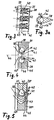
- Fig. 3
- ein in eine Ebene projizierter Ausschnitt aus einem ringförmigen, das Turbinenrad umgreifenden Bypass im Turbinengehäuse mit einer Mehrzahl parallel angeordneter, düsenförmiger Ejektorteile, über die zu förderndes Gas in den Bypass einzuleiten ist,
- Fig. 3a
- ein Ejektorteil in einer vergrößerten Darstellung,
- Fig. 4
- ein Ausschnitt aus dem Bypass mit zwei Ejektorteilen in einer alternativen Ausführung,
- Fig. 5
- ein Ausschnitt aus dem Bypass mit zwei Ejektorteilen in einer weiteren Ausführung.
- In den Figuren sind gleiche Bauteile mit gleichen Bezugszeichen versehen.
- Der in Fig. 1 dargestellten Brennkraftmaschine 1 - ein Ottomotor oder ein Dieselmotor - ist ein Abgasturbolader 2 mit einer Abgasturbine 3 im Abgasstrang 4 und einem Verdichter 5 im Ansaugtrakt 6 zugeordnet. Die Abgasturbine 3 wird von den unter Druck stehenden Abgasen der Brennkraftmaschine 1 angetrieben. Über eine Welle 7 wird der Verdichter 5 von der Abgasturbine 3 angetrieben, welcher Umgebungsluft ansaugt und auf einen erhöhten Ladedruck verdichtet. Die Abgasturbine 3 ist mit einer variablen Turbinengeometrie 8 zur veränderlichen Einstellung des wirksamen Turbineneintrittsquerschnittes ausgestattet.
- Stromab des Verdichters 5 ist im Ansaugtrakt 6 ein Ladeluftkühler angeordnet, in den die zuvor im Verdichter 5 komprimierte Luft eintritt und gekühlt wird. Stromab des Ladeluftkühlers 9 wird die Ladeluft unter Ladedruck den Zylindereinlässen der Brennkraftmaschine 1 zugeführt.
- Des Weiteren ist die Brennkraftmaschine 1 mit einer Abgasrückführungseinrichtung 10 ausgestattet, welche eine Rückführleitung 11 zwischen dem Abgasstrang 4 stromauf der Abgasturbine 3 und dem Ansaugtrakt 6 stromab des Ladeluftkühlers 9 umfasst. In die Rückführleitung 11 ist ein einstellbares Rückführventil 12 sowie ein Kühler 13 integriert.
- Im Abgasstrang 4 ist stromab der Abgasturbine 3 ein Katalysator 15 zur katalytischen Reinigung der abzublasenden Abgase angeordnet. Dem Katalysator 15 kann - im Falle eines Dieselmotors - ein Rußfilter 16 vorgeschaltet sein, über den Rußpartikel auszufiltern und gegebenenfalls abzubrennen sind.
- Weiterhin ist die Brennkraftmaschine 1 mit einer Kurbelgehäuse-Entlüftungseinrichtung 17 ausgestattet, die eine Gasförderleitung 18 zwischen dem Kurbelgehäuse der Brennkraftmaschine und der Abgasturbine 3 umfasst. In der Gasförderleitung 18 befindet sich ein Rückschlagventil 19, welches in Richtung Abgasturbolader 3 öffnet und ein unerwünschtes Rückströmen zurück in das Kurbelgehäuse verhindert. Gegebenenfalls kann das Ventil 19 aber auch als aktiv einstellbares Ventil ausgeführt sein.
- Der Brennkraftmaschine 1 ist darüber hinaus eine Lufteinblaseeinrichtung 20 zugeordnet, über die Frischluft aus der Umgebung angesaugt und über die Abgasturbine 3 dem Katalysator 15 sowie dem Rußfilter 16 zugeführt wird, um die Katalysatorfunktion insbesondere nach einem Kaltstart der Brennkraftmaschine sowie das Rußabbrennen im Rußfilter zu unterstützen. Die Lufteinblaseeinrichtung 20 umfasst eine Gasförderleitung 21, über die die Verbrennungsluft aus der Atmosphäre angesaugt wird und in der sich ein einstellbares Ventil 23 befindet. Die Gasförderleitung 21 der Lufteinblaseeinrichtung 20 mündet mit der Gasförderleitung 18 der Kurbelgehäuse-Entlüftungseinrichtung 17 in einen gemeinsamen Leitungsabschnitt 22, welcher in die Abgasturbine 3 geführt ist.
- Über eine Regel- und Steuereinheit 14 sind sämtliche einstellbaren Aggregate der Brennkraftmaschine in Abhängigkeit von Zustands- und Betriebsgrößen einzustellen. Dies betrifft insbesondere das Rückführventil 12 in der Abgasrückführungseinrichtung 10, die variable Turbinengeometrie 8 in der Abgasturbine 3 und das Ventil 23 in der Lufteinblaseeinrichtung 20.
- Der Schnittdarstellung der Abgasturbine 3 gemäß Fig. 2 ist zu entnehmen, dass im Turbinengehäuse 24 ein Spiralkanal 25 ausgebildet ist, der einen Sammelraum für das eingeleitete Abgas der Brennkraftmaschine bildet. Das Abgas wird aus dem Spiralkanal 25 über einen Strömungseintrittsquerschnitt 26, in dem sich die variable Turbinengeometrie 8 befindet, radial auf das Turbinenrad 27 geführt. Das auf das Turbinenrad 27 auftreffende Abgas treibt dieses an und verlässt anschließend im entspannten Zustand über den Austrittsbereich 28 die Abgasturbine 3 und wird im weiteren Verlauf im Abgasstrang einer Reinigung unterzogen.
- Am Turbinengehäuse 24 ist ein Anschlussstutzen 29 ausgebildet, in dem sich ein Anschlusskanal 30 befindet, wobei mit dem Anschlussstutzen 29 der Leitungsabschnitt 22 der Kurbelgehäuse-Entlüftungseinrichtung und/oder der Lufteinblaseeinrichtung (Fig. 1) zu verbinden ist. Über den Anschlussstutzen 29 werden entweder Entlüftungsgase aus dem Kurbelgehäuse oder Umgebungsluft der Abgasturbine 3 zugeführt.
- Der Turbineneintrittsquerschnitt 26, über den Abgas aus dem Abgassammelraum bzw. Spiralkanal 25 dem Turbinenrad 27 zuführbar ist, wird von einem Abgas-Bypass 31 überbrückt, welcher im Turbinengehäuse 24 ausgebildet ist und einen als Austrittsdiffusor 36 ausgeführten Abströmkanal, welcher den Austrittsbereich 28 der Abgasturbine bildet, umgreift. Der Bypass 31 zweigt vom Spiralkanal 25 ab und mündet axial in den Austrittsbereich 28. Über den Bypass wird ein Teilmassenstrom des im Spiralkanal 25 befindlichen Abgases gemäß Pfeilrichtung 33 in Radialrichtung in den Bypass 31 eingeleitet und nach Durchströmen des Bypass in Pfeilrichtung 37 axial wieder aus dem Bypass abgeleitet. Der Anschlusskanal 30 mündet radial in den axial verlaufenden Abschnitt des Bypass 31 ein. Aufgrund des Druckgefälles zwischen dem Spiralkanal 25 und dem Austrittsbereich 28 wird im Ejektor eine Pumpwirkung erzielt, über die über den Leitungsabschnitt 22 und den Anschlusskanal 30 zugeführtes Gas in den Bypass 31 und weiter in den Austrittsbereich 28 gefördert wird.
- Der Bypass 31 ist zweckmäßig ringförmig ausgebildet. Im Bypass ist vorteilhaft zumindest ein Ejektorteil 38 angeordnet, welches die Funktion einer Düse im Bypass 31 übernimmt und über das Gas der Gasfördereinrichtung in den Bypass einzuleiten ist. Zweckmäßig sind eine Mehrzahl von über den Umfang verteilter Ejektorteile 38 im Bypass vorgesehen, über die jeweils Gas in den Bypass einzuführen ist, wobei gegebenenfalls auch nur über eines oder eine beschränkte Anzahl von Ejektorteilen das Gas eingeleitet werden kann. In dem Ejektorteil 38 ist ein Mündungskanal 39 ausgebildet, welcher mit dem Anschlusskanal 30 im Anschlussstutzen 29 kommuniziert und welcher etwa senkrecht zur Strömungsrichtung des Bypass 31 verläuft. In den Mündungskanal 39 im Ejektorteil 38 ist eine Mündungsöffnung eingebracht (in den Fig. 3 bis 5 mit Bezugszeichen 40 gekennzeichnet), über die das zugeführte Gas in den Bypass 31 abgeleitet wird.
- Die eine Düse bildenden Ejektorteile im Bypass 31 stellen aufgrund ihres reduzierten Strömungsquerschnittes sicher, dass nur ein verhältnismäßig kleiner Anteil des Abgases über den Bypass 31 unter Umgehung des Turbinenrades in den Austrittsbereich der Abgasturbine geleitet wird. Zweckmäßig beträgt der durch den Bypass 31 geleitete Abgasmassenstrom nicht mehr als 5 % des gesamten, die Abgasturbine passierenden Abgasmassenstromes, wobei vorteilhaft Werte zwischen 1 % und 2 % realisiert werden.
- In Fig. 3 ist ein Ausschnitt eines in die Ebene projizierten Segmentes eines Bypass 31 dargestellt. Im Bypass sind eine Mehrzahl über den Umfang gleichmäßig verteilter Ejektorteile 38 parallel zueinander angeordnet, welche strömungsgünstig konturiert sind und von dem Abgas in Pfeilrichtung 41 umströmt werden. Über die Mündungskanäle 39 wird dem Bypass 31 das zu fördernde Gas zugeführt, siehe auch Fig. 3a. Jeder Mündungskanal 39 ist über zwei schlitzförmige Mündungsöffnungen 40 mit dem Bypass verbunden; über die Mündungsöffnungen 40 kann in Pfeilrichtung 42 das zuzuführende Gas in den Bypass 31 einströmen.
- Je zwei parallel angeordnete und benachbarte Ejektorteile 38 bilden eine Düse innerhalb des Bypass 31, dessen engster Düsenquerschnitt sich im Bereich eines kreisrunden Abschnittes der Ejektorteile 38 befindet, die sich in Strömungsrichtung des Abgases gesehen etwa dreieckförmig verjüngen. Der Düseneintrittsquerschnitt - die angeströmte Vorderseite der Ejektorteile - ist mit Bezugszeichen 43 versehen, der engste Düsenquerschnitt zwischen benachbarten Ejektorteilen mit Bezugszeichen 44 und der Düsenaustrittsquerschnitt - im Bereich des spitzen Endes auf der Abströmseite - mit Bezugszeichen 45. Die Mündungsöffnungen 40 befinden sich stromab des engsten Düsenquerschnittes 44.
- Auch in den Ausführungsbeispielen gemäß den Fig. 4 und 5 befinden sich die Mündungsöffnungen 40 stromab des engsten Düsenquerschnittes zwischen benachbarten Ejektorteilen 38. Gemäß Fig. 4 sind jeweils zwei benachbarte Ejektorteile 38 bezüglich einer in Strömungsrichtung verlaufenden Ebene 46 spiegelsymmetrisch ausgebildet, wobei der den Mündungskanal 39 im Ejektorteil 38 begrenzende Wandabschnitt jeweils kreisförmig ausgeführt ist. Die Mündungsöffnungen 40 sind in der Weise platziert, dass das in Pfeilrichtung 42 ausströmende Gas etwa eine Strömungsrichtung besitzt, die parallel ist zur Strömungsrichtung des in Pfeilrichtung 41 den engsten Düsenquerschnitt passierenden Abgases.
- Beim Ausführungsbeispiel gemäß Fig. 5 sind benachbarte Ejektorteile 38' und 38" unterschiedlich aufgebaut. Ein erstes Ejektorteil 38' entspricht etwa der Ausführung gemäß Fig. 4 mit einem Mündungskanal 39, der über eine Mündungsöffnung 40 stromab des engsten Düsenquerschnittes 44 in den Bypass 31 mündet. Ein zweites Ejektorteil 38" besitzt keinen Mündungskanal bzw. keine Mündungsöffnung für die Zufuhr von Gas, sondern weist eine teilkreisförmige Ausbuchtung 47 auf, die komplementär zum kreisförmigen Abschnitt des benachbarten Ejektorteiles 38' ausgebildet ist, in welchem sich der Mündungskanal 39 befindet. Hierdurch ergibt sich ein bogenförmiger Strömungskanal zwischen den benachbarten Ejektorteilen 38' und 38", dessen engster Düsenquerschnitt 44 in Richtung des Düsenaustrittsquerschnittes 45 verschoben ist. Über die bogenförmige Ausgestaltung des Düsenkanals ist eine Umlenkung der Abgasströmung durch den Bypass möglich, so dass die Einströmung des Abgases über den Düseneintrittsquerschnitt 43 eine andere Richtung aufweist als die Abströmung im Düsenaustrittsquerschnitt 45.
Claims (13)
- Abgasturbolader für eine Brennkraftmaschine, mit einem Verdichter (5) im Ansaugtrakt (6) und einer Abgasturbine (3) im Abgasstrang (4), wobei die Abgasturbine (3) in einem Turbinengehäuse (24) einen Abgassammelraum aufweist, dessen Abgas dem Turbinenrad (27) über einen Turbineneintrittsquerschnitt zuführbar ist, mit einem den Turbineneintrittsquerschnitt überbrückenden Abgas-Bypass (31),
dadurch gekennheichnet,
dass der Abgas-Bypass (31) im Turbinengehäuse (24) ausgebildet ist und den Abgassammelraum mit einem Austrittsbereich (28) der Abgasturbine (3) verbindet, und dass die Abgasturbine (3) eine Pumpe für eine Gasfördereinrichtung bildet, wobei eine der Gasfördereinrichtung zugeordnete Gasförderleitung (18, 21) über einen im Turbinengehäuse (24) ausgebildeten Anschlussstutzen (29), in den ein Anschlusskanal (30) eingebracht ist, in den Abgas-Bypass (31) mündet. - Abgasturbolader nach Anspruch 1,
dadurch gekennzeichnet,
dass in den Abgas-Bypass (31) eine Düse mit verjüngtem Querschnitt integriert ist und dass die Gasförderleitung (18, 21) stromab des engsten Querschnitts der Düse in den Abgas-Bypass (31) mündet. - Abgasturbolader nach Anspruch 1 oder 2,
dadurch gekennzeichnet,
dass in den Abgas-Bypass (31) ein strömungsgünstig konturiertes und vom Abgas umströmtes Ejektorteil (38) integriert ist, welches eine Mündungsöffnung (40) in den Abgas-Bypass (31) für das zuzuführende Gas aufweist. - Abgasturbolader nach Anspruch 3,
dadurch gekennzeichnet,
dass im Ejektorteil (38) ein sich senkrecht zur Anströmrichtung des Abgases erstreckender Mündungsöffnung (40) für den Anschluss der Gasförderleitung (18, 21) ausgebildet ist und
dass die Mündungsöffnung (40) vom Mündungskanal (39) abzweigt. - Abgasturbolader nach Anspruch 3 oder 4,
dadurch gekennzeichnet,
dass das Ejektorteil (38) im Bypass (31) einen sich in Strömungsrichtung verjüngenden Querschnitt aufweist. - Abgasturbolader nach einem der Ansprüche 3 bis 5,
dadurch gekennzeichnet,
dass der Bypass (31) ringförmig um das Turbinenrad (27) angeordnet ist und über den Umfang_des Bypass (31) verteilt eine Mehrzahl von Ejektorteilen (38) angeordnet sind, wobei zwischen zwei benachbarten Ejektorteilen (38) jeweils ein engster Düsenquerschnitt (44) gebildet ist. - Abgasturbolader nach Anspruch 6,
dadurch gekennzeichnet,
dass über den Umfang verteilt gleichartige Ejektorteile (38) angeordnet sind. - Abgasturbolader nach Anspruch 6,
dadurch gekennzeichnet,
dass über den Umfang verteilt zumindest zwei unterschiedlich konturierte Ejektorteile (38) angeordnet sind, wobei jeweils zwei benachbarte Ejektorteile (38) einen Düsenquerschnitt für das Abgas begrenzen, dessen Einströmung und dessen Abströmung voneinander abweichende Richtungen besitzen. - Abgasturbolader nach Anspruch 8,
dadurch gekennzeichnet,
dass die beiden Ejektorteile (38) im Bereich des engsten Düsenquerschnitts (44) konvex bzw. konkav ausgebildet sind. - Abgasturbolader nach einem der Ansprüche 3 bis 9,
dadurch gekennzeichnet,
dass die Mündungsöffnung (40) schlitzförmig ausgebildet ist. - Abgasturbolader nach einem der Ansprüche 3 bis 10,
dadurch gekennzeichnet,
dass die Ausrichtung der Mündungsöffnung (40) näherungsweise parallel zur Ausrichtung des Düsenaustrittsquerschnitts (45) ist. - Verwendung eines Abgasturboladers nach einem der Ansprüche 1 bis 11 in einer Brennkraftmaschine, wobei die Gasfördereinrichtung eine Kurbelgehäuse-Entlüftungseinrichtung (17) ist und die Gasförderleitung (18) vom Kurbelgehäuse abzweigt.
- Verwendung eines Abgasturboladers nach einem der Ansprüche 1 bis 12 in einer Brennkraftmaschine, wobei die Gasfördereinrichtung eine Lufteinblaseeinrichtung (20) ist und der Abgasturbine (3) Umgebungsluft über die Gasförderleitung (18) zuführbar ist.
Applications Claiming Priority (3)
| Application Number | Priority Date | Filing Date | Title |
|---|---|---|---|
| DE10260778A DE10260778A1 (de) | 2002-12-23 | 2002-12-23 | Abgasturbolader für eine Brennkraftmaschine |
| DE10260778 | 2002-12-23 | ||
| PCT/EP2003/013071 WO2004059146A1 (de) | 2002-12-23 | 2003-11-21 | Abgasturbolader für eine brennkraftmaschine |
Publications (2)
| Publication Number | Publication Date |
|---|---|
| EP1576265A1 EP1576265A1 (de) | 2005-09-21 |
| EP1576265B1 true EP1576265B1 (de) | 2006-04-12 |
Family
ID=32404226
Family Applications (1)
| Application Number | Title | Priority Date | Filing Date |
|---|---|---|---|
| EP03775381A Expired - Lifetime EP1576265B1 (de) | 2002-12-23 | 2003-11-21 | Abgasturbolader für eine brennkraftmaschine |
Country Status (4)
| Country | Link |
|---|---|
| US (1) | US7162872B2 (de) |
| EP (1) | EP1576265B1 (de) |
| DE (2) | DE10260778A1 (de) |
| WO (1) | WO2004059146A1 (de) |
Families Citing this family (26)
| Publication number | Priority date | Publication date | Assignee | Title |
|---|---|---|---|---|
| SE524780C2 (sv) * | 2003-02-27 | 2004-10-05 | Volvo Lastvagnar Ab | Förbränningsmotor med turboaggregat |
| US7154931B2 (en) * | 2004-06-22 | 2006-12-26 | Ksy Corporation | Laser with Brayton cycle outlet pump |
| DE102005020482A1 (de) | 2005-04-29 | 2006-11-09 | Mahle International Gmbh | Brennkraftmaschine mit Abgasrückführung |
| SE529167C2 (sv) * | 2005-06-15 | 2007-05-22 | Volvo Lastvagnar Ab | Vevhusventilation |
| FR2891011A1 (fr) * | 2005-09-21 | 2007-03-23 | Melchior Jean F | Dispositif de suralimentation pour moteur a combustion interne, et vehicule automobile equipe d'un tel dispositif |
| DE102005046507A1 (de) * | 2005-09-29 | 2007-04-05 | Daimlerchrysler Ag | Brennkraftmaschine mit zwei hintereinander geschalteten Abgasturboladern |
| DE102007046667A1 (de) * | 2007-09-27 | 2009-04-09 | Behr Gmbh & Co. Kg | Mehrstufige Aufladegruppe, Mehrstufige Aufladevorrichtung und Aufladesystem |
| CN105501388A (zh) * | 2008-04-01 | 2016-04-20 | 国立研究开发法人海上技术安全研究所 | 船舶的摩擦阻力减小装置 |
| US8061974B2 (en) * | 2008-09-11 | 2011-11-22 | Honeywell International Inc. | Compressor with variable-geometry ported shroud |
| DE112010000936T5 (de) * | 2009-02-26 | 2012-08-02 | Borgwarner Inc. | Verbrennungsmotor |
| WO2011002732A2 (en) * | 2009-07-02 | 2011-01-06 | Borgwarner Inc. | Turbocharger turbine |
| US8424304B2 (en) * | 2009-11-03 | 2013-04-23 | Honeywell International Inc. | Turbine assembly for a turbocharger, having two asymmetric volutes that are sequentially activated, and associated method |
| DE102012112396A1 (de) * | 2012-12-17 | 2014-07-03 | Ihi Charging Systems International Gmbh | Abgasführungsabschnitt für eine Turbine und Verfahren zur Regelung einer Turbine |
| DE102013219329B4 (de) * | 2013-09-25 | 2022-12-08 | Volkswagen Aktiengesellschaft | Turbinenanordnung für eine Brennkraftmaschine und aufladbare Brennkraftmaschine |
| DE102015207573B4 (de) * | 2015-04-24 | 2023-07-06 | Ford Global Technologies, Llc | Brennkraftmaschine mit kombiniertem Abgasnachbehandlungssystem |
| US9739166B1 (en) | 2016-08-31 | 2017-08-22 | Borgwarner Inc. | VTG internal by-pass |
| DE102016119255A1 (de) * | 2016-10-10 | 2018-04-12 | Ihi Charging Systems International Gmbh | Abgasführungsabschnitt für einen Abgasturbolader und Abgasstrang für eine Verbrennungskraftmaschine sowie Verfahren zum Betreiben eines Abgasturboladers |
| US10985608B2 (en) | 2016-12-13 | 2021-04-20 | General Electric Company | Back-up power system for a component and method of assembling same |
| DE102019106682B4 (de) * | 2019-03-15 | 2022-07-07 | Bürkert Werke GmbH & Co. KG | Druckregler |
| JP7303763B2 (ja) * | 2020-02-28 | 2023-07-05 | 三菱重工マリンマシナリ株式会社 | 排気ディフューザ及びタービンハウジング、並びに過給機 |
| FR3114125A1 (fr) * | 2020-09-17 | 2022-03-18 | Psa Automobiles Sa | Moteur a injection d’air a l’echappement |
| DE102020007366B4 (de) * | 2020-12-03 | 2023-12-14 | Mercedes-Benz Group AG | Verbrennungskraftmaschine für ein Kraftfahrzeug, insbesondere für einen Kraftwagen, sowie Kraftfahrzeug |
| FR3122212B1 (fr) * | 2021-04-21 | 2023-11-24 | Psa Automobiles Sa | Moteur a combustion interne equipe d’un dispositif d’injection d’air a l’echappement |
| US11680501B2 (en) * | 2021-09-21 | 2023-06-20 | Deere & Company | Internal combustion engine and crankcase ventilation system |
| DE102022117716B3 (de) | 2022-07-15 | 2023-06-07 | Dr. Ing. H.C. F. Porsche Aktiengesellschaft | Abgassystem einer Brennkraftmaschine |
| WO2024053148A1 (ja) * | 2022-09-07 | 2024-03-14 | 株式会社Ihi | タービン |
Family Cites Families (20)
| Publication number | Priority date | Publication date | Assignee | Title |
|---|---|---|---|---|
| US1531080A (en) * | 1925-03-24 | Telephone-exchange system | ||
| US2366365A (en) * | 1942-02-09 | 1945-01-02 | Ford Motor Co | Supercharger |
| GB1531080A (en) * | 1977-08-26 | 1978-11-01 | Gec Diesels Ltd | Crankcase ventilation of internal combustion piston engines |
| JPS5525505A (en) * | 1978-08-10 | 1980-02-23 | Ishikawajima Harima Heavy Ind Co Ltd | Supercharger provided on turbine outlet with ejector |
| DE2939152C2 (de) * | 1979-09-27 | 1983-10-20 | Bayerische Motoren Werke AG, 8000 München | Turbine eines Abgasturboladers für Brennkraftmaschinen |
| JPS5683517A (en) * | 1979-12-12 | 1981-07-08 | Hitachi Ltd | Radial flow turbine for exhaust turbine supercharger |
| JPS57124023A (en) * | 1981-01-26 | 1982-08-02 | Mazda Motor Corp | Secondary air feeder for multicylinder engine with supercharger |
| JPS618421A (ja) * | 1984-06-22 | 1986-01-16 | Toyota Motor Corp | タ−ボチヤ−ジヤの排気バイパス装置 |
| DE3606944A1 (de) * | 1986-03-04 | 1987-09-10 | Audi Ag | Abgasturbolader |
| DE4312078C2 (de) * | 1993-04-13 | 1995-06-01 | Daimler Benz Ag | Abgasturbolader für eine aufgeladene Brennkraftmaschine |
| DE19540060A1 (de) * | 1995-10-27 | 1997-04-30 | Daimler Benz Ag | Motorbremsvorrichtung |
| DE19618160C2 (de) * | 1996-05-07 | 1999-10-21 | Daimler Chrysler Ag | Abgasturbolader für eine Brennkraftmaschine |
| DE19651498C1 (de) * | 1996-12-11 | 1998-04-16 | Daimler Benz Ag | Abgasturboladerturbine für eine Brennkraftmaschine |
| US6123061A (en) * | 1997-02-25 | 2000-09-26 | Cummins Engine Company, Inc. | Crankcase ventilation system |
| JP2893396B2 (ja) | 1997-09-01 | 1999-05-17 | 株式会社東京機械製作所 | 紙票添付装置 |
| DE19836677C2 (de) * | 1998-08-13 | 2001-04-19 | Daimler Chrysler Ag | Motorbremseinrichtung für eine Brennkraftmaschine mit einem Abgasturbolader |
| US6202413B1 (en) * | 1999-02-04 | 2001-03-20 | Cummins Engine Company, Inc. | Multiple nozzle ejector for wastegated turbomachinery |
| JP2000274254A (ja) * | 1999-03-24 | 2000-10-03 | Hitachi Ltd | ターボチャージャ |
| US6276139B1 (en) * | 2000-03-16 | 2001-08-21 | Ford Global Technologies, Inc. | Automotive engine with controlled exhaust temperature and oxygen concentration |
| US6767185B2 (en) * | 2002-10-11 | 2004-07-27 | Honeywell International Inc. | Turbine efficiency tailoring |
-
2002
- 2002-12-23 DE DE10260778A patent/DE10260778A1/de not_active Withdrawn
-
2003
- 2003-11-21 EP EP03775381A patent/EP1576265B1/de not_active Expired - Lifetime
- 2003-11-21 WO PCT/EP2003/013071 patent/WO2004059146A1/de not_active Ceased
- 2003-11-21 DE DE50302991T patent/DE50302991D1/de not_active Expired - Lifetime
-
2005
- 2005-06-22 US US11/159,391 patent/US7162872B2/en not_active Expired - Fee Related
Also Published As
| Publication number | Publication date |
|---|---|
| WO2004059146A1 (de) | 2004-07-15 |
| US20050252211A1 (en) | 2005-11-17 |
| DE10260778A1 (de) | 2004-07-01 |
| US7162872B2 (en) | 2007-01-16 |
| DE50302991D1 (de) | 2006-05-24 |
| EP1576265A1 (de) | 2005-09-21 |
Similar Documents
| Publication | Publication Date | Title |
|---|---|---|
| EP1576265B1 (de) | Abgasturbolader für eine brennkraftmaschine | |
| EP1316699B1 (de) | Abgasturbolader für eine Brennkraftmaschine und Verfahren zum Betrieb einer aufgeladenen Brennkraftmaschine | |
| DE4312078C2 (de) | Abgasturbolader für eine aufgeladene Brennkraftmaschine | |
| DE60117448T2 (de) | Venturi-Bypass eines Abgasrückführungssystems | |
| DE112011102931B4 (de) | Kompressorrückführung in ringförmiges Volumen | |
| DE10116643C2 (de) | Hubkolbenbrennkraftmaschine | |
| DE112006000420B4 (de) | Ladedruckwastegateeinrichtung zur Abgasrückführungsunterstützung | |
| WO2007093367A1 (de) | Verdichter für eine brennkraftmaschine | |
| EP2025896A2 (de) | Radialverdichter für einen Turbolader | |
| EP3141735B1 (de) | Brennkraftmaschine mit booster | |
| DE10054601A1 (de) | Einleitungsventurimittel für ein Abgaszirkulationssystem in einem Verbrennungsmotor | |
| WO2009018887A1 (de) | Abgasturbolader für eine hubkolben-brennkraftmaschine | |
| DE10343756B4 (de) | Lufteinlasskühlsystem und -verfahren | |
| DE3529280C1 (de) | Vorrichtung zur Erhoehung der Drehzahl eines Abgasturboladers an einer Brennkraftmaschine | |
| WO2005001257A1 (de) | Brennkraftmaschine mit einem verdichter im ansaugtrakt und verfahren hierzu | |
| WO2006117073A1 (de) | Abgasturbolader für eine brennkraftmaschine | |
| DE102004049218A1 (de) | Brennkraftmaschine mit Abgasrückführungseinrichtung | |
| DE102009041223B4 (de) | Verfahren zum Auslegen eines Antriebssystems | |
| EP4405574B1 (de) | Verbrennungskraftmaschine für ein kraftfahrzeug, insbesondere für einen kraftwagen | |
| EP1619365B1 (de) | Abgasnachbehandlung mit sequentieller Aufladung | |
| DE10232519A1 (de) | Abgasturbolader für eine Brennkraftmaschine | |
| EP2602468B1 (de) | Brennkraftmaschine mit Abgasrückführungseinrichtung | |
| DE10226694A1 (de) | Aufgeladene Brennkraftmaschine mit einer Kurbelgehäuseentlüftungseinrichtung | |
| DE102007021934A1 (de) | Ladervorrichtung für eine Brennkraftmaschine sowie Brennkraftmaschine | |
| DE10260779A1 (de) | Abgasturbolader |
Legal Events
| Date | Code | Title | Description |
|---|---|---|---|
| PUAI | Public reference made under article 153(3) epc to a published international application that has entered the european phase |
Free format text: ORIGINAL CODE: 0009012 |
|
| 17P | Request for examination filed |
Effective date: 20050518 |
|
| AK | Designated contracting states |
Kind code of ref document: A1 Designated state(s): AT BE BG CH CY CZ DE DK EE ES FI FR GB GR HU IE IT LI LU MC NL PT RO SE SI SK TR |
|
| GRAP | Despatch of communication of intention to grant a patent |
Free format text: ORIGINAL CODE: EPIDOSNIGR1 |
|
| RIN1 | Information on inventor provided before grant (corrected) |
Inventor name: SCHMID, WOLFRAM Inventor name: SUMSER, SIEGFRIED |
|
| GRAS | Grant fee paid |
Free format text: ORIGINAL CODE: EPIDOSNIGR3 |
|
| GRAA | (expected) grant |
Free format text: ORIGINAL CODE: 0009210 |
|
| AK | Designated contracting states |
Kind code of ref document: B1 Designated state(s): DE FR GB IT |
|
| PG25 | Lapsed in a contracting state [announced via postgrant information from national office to epo] |
Ref country code: IT Free format text: LAPSE BECAUSE OF FAILURE TO SUBMIT A TRANSLATION OF THE DESCRIPTION OR TO PAY THE FEE WITHIN THE PRESCRIBED TIME-LIMIT;WARNING: LAPSES OF ITALIAN PATENTS WITH EFFECTIVE DATE BEFORE 2007 MAY HAVE OCCURRED AT ANY TIME BEFORE 2007. THE CORRECT EFFECTIVE DATE MAY BE DIFFERENT FROM THE ONE RECORDED. Effective date: 20060412 |
|
| RBV | Designated contracting states (corrected) |
Designated state(s): DE FR GB IT |
|
| REG | Reference to a national code |
Ref country code: GB Ref legal event code: FG4D Free format text: NOT ENGLISH |
|
| GBT | Gb: translation of ep patent filed (gb section 77(6)(a)/1977) |
Effective date: 20060412 |
|
| REF | Corresponds to: |
Ref document number: 50302991 Country of ref document: DE Date of ref document: 20060524 Kind code of ref document: P |
|
| ET | Fr: translation filed | ||
| PLBE | No opposition filed within time limit |
Free format text: ORIGINAL CODE: 0009261 |
|
| STAA | Information on the status of an ep patent application or granted ep patent |
Free format text: STATUS: NO OPPOSITION FILED WITHIN TIME LIMIT |
|
| 26N | No opposition filed |
Effective date: 20070115 |
|
| REG | Reference to a national code |
Ref country code: FR Ref legal event code: CA Ref country code: FR Ref legal event code: CD |
|
| PGFP | Annual fee paid to national office [announced via postgrant information from national office to epo] |
Ref country code: FR Payment date: 20100603 Year of fee payment: 7 |
|
| PGFP | Annual fee paid to national office [announced via postgrant information from national office to epo] |
Ref country code: DE Payment date: 20100511 Year of fee payment: 7 Ref country code: IT Payment date: 20100430 Year of fee payment: 7 |
|
| PGFP | Annual fee paid to national office [announced via postgrant information from national office to epo] |
Ref country code: GB Payment date: 20100423 Year of fee payment: 7 |
|
| GBPC | Gb: european patent ceased through non-payment of renewal fee |
Effective date: 20101121 |
|
| REG | Reference to a national code |
Ref country code: FR Ref legal event code: ST Effective date: 20110801 |
|
| REG | Reference to a national code |
Ref country code: DE Ref legal event code: R119 Ref document number: 50302991 Country of ref document: DE Effective date: 20110601 Ref country code: DE Ref legal event code: R119 Ref document number: 50302991 Country of ref document: DE Effective date: 20110531 |
|
| PG25 | Lapsed in a contracting state [announced via postgrant information from national office to epo] |
Ref country code: FR Free format text: LAPSE BECAUSE OF NON-PAYMENT OF DUE FEES Effective date: 20101130 |
|
| PG25 | Lapsed in a contracting state [announced via postgrant information from national office to epo] |
Ref country code: GB Free format text: LAPSE BECAUSE OF NON-PAYMENT OF DUE FEES Effective date: 20101121 |
|
| PG25 | Lapsed in a contracting state [announced via postgrant information from national office to epo] |
Ref country code: IT Free format text: LAPSE BECAUSE OF NON-PAYMENT OF DUE FEES Effective date: 20101121 |
|
| PG25 | Lapsed in a contracting state [announced via postgrant information from national office to epo] |
Ref country code: DE Free format text: LAPSE BECAUSE OF NON-PAYMENT OF DUE FEES Effective date: 20110531 |