EP1576265B1 - Turbocompresseur a gaz d'echappement pour moteur a combustion - Google Patents
Turbocompresseur a gaz d'echappement pour moteur a combustion Download PDFInfo
- Publication number
- EP1576265B1 EP1576265B1 EP03775381A EP03775381A EP1576265B1 EP 1576265 B1 EP1576265 B1 EP 1576265B1 EP 03775381 A EP03775381 A EP 03775381A EP 03775381 A EP03775381 A EP 03775381A EP 1576265 B1 EP1576265 B1 EP 1576265B1
- Authority
- EP
- European Patent Office
- Prior art keywords
- exhaust gas
- bypass
- turbine
- section
- turbocharger according
- Prior art date
- Legal status (The legal status is an assumption and is not a legal conclusion. Google has not performed a legal analysis and makes no representation as to the accuracy of the status listed.)
- Expired - Lifetime
Links
Images


Classifications
-
- F—MECHANICAL ENGINEERING; LIGHTING; HEATING; WEAPONS; BLASTING
- F01—MACHINES OR ENGINES IN GENERAL; ENGINE PLANTS IN GENERAL; STEAM ENGINES
- F01N—GAS-FLOW SILENCERS OR EXHAUST APPARATUS FOR MACHINES OR ENGINES IN GENERAL; GAS-FLOW SILENCERS OR EXHAUST APPARATUS FOR INTERNAL-COMBUSTION ENGINES
- F01N3/00—Exhaust or silencing apparatus having means for purifying, rendering innocuous, or otherwise treating exhaust
- F01N3/08—Exhaust or silencing apparatus having means for purifying, rendering innocuous, or otherwise treating exhaust for rendering innocuous
- F01N3/10—Exhaust or silencing apparatus having means for purifying, rendering innocuous, or otherwise treating exhaust for rendering innocuous by thermal or catalytic conversion of noxious components of exhaust
- F01N3/18—Exhaust or silencing apparatus having means for purifying, rendering innocuous, or otherwise treating exhaust for rendering innocuous by thermal or catalytic conversion of noxious components of exhaust characterised by methods of operation; Control
- F01N3/22—Control of additional air supply only, e.g. using by-passes or variable air pump drives
-
- F—MECHANICAL ENGINEERING; LIGHTING; HEATING; WEAPONS; BLASTING
- F01—MACHINES OR ENGINES IN GENERAL; ENGINE PLANTS IN GENERAL; STEAM ENGINES
- F01N—GAS-FLOW SILENCERS OR EXHAUST APPARATUS FOR MACHINES OR ENGINES IN GENERAL; GAS-FLOW SILENCERS OR EXHAUST APPARATUS FOR INTERNAL-COMBUSTION ENGINES
- F01N3/00—Exhaust or silencing apparatus having means for purifying, rendering innocuous, or otherwise treating exhaust
- F01N3/02—Exhaust or silencing apparatus having means for purifying, rendering innocuous, or otherwise treating exhaust for cooling, or for removing solid constituents of, exhaust
- F01N3/021—Exhaust or silencing apparatus having means for purifying, rendering innocuous, or otherwise treating exhaust for cooling, or for removing solid constituents of, exhaust by means of filters
- F01N3/033—Exhaust or silencing apparatus having means for purifying, rendering innocuous, or otherwise treating exhaust for cooling, or for removing solid constituents of, exhaust by means of filters in combination with other devices
- F01N3/035—Exhaust or silencing apparatus having means for purifying, rendering innocuous, or otherwise treating exhaust for cooling, or for removing solid constituents of, exhaust by means of filters in combination with other devices with catalytic reactors
-
- F—MECHANICAL ENGINEERING; LIGHTING; HEATING; WEAPONS; BLASTING
- F01—MACHINES OR ENGINES IN GENERAL; ENGINE PLANTS IN GENERAL; STEAM ENGINES
- F01N—GAS-FLOW SILENCERS OR EXHAUST APPARATUS FOR MACHINES OR ENGINES IN GENERAL; GAS-FLOW SILENCERS OR EXHAUST APPARATUS FOR INTERNAL-COMBUSTION ENGINES
- F01N3/00—Exhaust or silencing apparatus having means for purifying, rendering innocuous, or otherwise treating exhaust
- F01N3/08—Exhaust or silencing apparatus having means for purifying, rendering innocuous, or otherwise treating exhaust for rendering innocuous
- F01N3/10—Exhaust or silencing apparatus having means for purifying, rendering innocuous, or otherwise treating exhaust for rendering innocuous by thermal or catalytic conversion of noxious components of exhaust
- F01N3/18—Exhaust or silencing apparatus having means for purifying, rendering innocuous, or otherwise treating exhaust for rendering innocuous by thermal or catalytic conversion of noxious components of exhaust characterised by methods of operation; Control
- F01N3/22—Control of additional air supply only, e.g. using by-passes or variable air pump drives
- F01N3/222—Control of additional air supply only, e.g. using by-passes or variable air pump drives using electric valves only
-
- F—MECHANICAL ENGINEERING; LIGHTING; HEATING; WEAPONS; BLASTING
- F01—MACHINES OR ENGINES IN GENERAL; ENGINE PLANTS IN GENERAL; STEAM ENGINES
- F01N—GAS-FLOW SILENCERS OR EXHAUST APPARATUS FOR MACHINES OR ENGINES IN GENERAL; GAS-FLOW SILENCERS OR EXHAUST APPARATUS FOR INTERNAL-COMBUSTION ENGINES
- F01N3/00—Exhaust or silencing apparatus having means for purifying, rendering innocuous, or otherwise treating exhaust
- F01N3/08—Exhaust or silencing apparatus having means for purifying, rendering innocuous, or otherwise treating exhaust for rendering innocuous
- F01N3/10—Exhaust or silencing apparatus having means for purifying, rendering innocuous, or otherwise treating exhaust for rendering innocuous by thermal or catalytic conversion of noxious components of exhaust
- F01N3/18—Exhaust or silencing apparatus having means for purifying, rendering innocuous, or otherwise treating exhaust for rendering innocuous by thermal or catalytic conversion of noxious components of exhaust characterised by methods of operation; Control
- F01N3/22—Control of additional air supply only, e.g. using by-passes or variable air pump drives
- F01N3/225—Electric control of additional air supply
-
- F—MECHANICAL ENGINEERING; LIGHTING; HEATING; WEAPONS; BLASTING
- F01—MACHINES OR ENGINES IN GENERAL; ENGINE PLANTS IN GENERAL; STEAM ENGINES
- F01N—GAS-FLOW SILENCERS OR EXHAUST APPARATUS FOR MACHINES OR ENGINES IN GENERAL; GAS-FLOW SILENCERS OR EXHAUST APPARATUS FOR INTERNAL-COMBUSTION ENGINES
- F01N3/00—Exhaust or silencing apparatus having means for purifying, rendering innocuous, or otherwise treating exhaust
- F01N3/08—Exhaust or silencing apparatus having means for purifying, rendering innocuous, or otherwise treating exhaust for rendering innocuous
- F01N3/10—Exhaust or silencing apparatus having means for purifying, rendering innocuous, or otherwise treating exhaust for rendering innocuous by thermal or catalytic conversion of noxious components of exhaust
- F01N3/24—Exhaust or silencing apparatus having means for purifying, rendering innocuous, or otherwise treating exhaust for rendering innocuous by thermal or catalytic conversion of noxious components of exhaust characterised by constructional aspects of converting apparatus
- F01N3/30—Arrangements for supply of additional air
-
- F—MECHANICAL ENGINEERING; LIGHTING; HEATING; WEAPONS; BLASTING
- F02—COMBUSTION ENGINES; HOT-GAS OR COMBUSTION-PRODUCT ENGINE PLANTS
- F02B—INTERNAL-COMBUSTION PISTON ENGINES; COMBUSTION ENGINES IN GENERAL
- F02B37/00—Engines characterised by provision of pumps driven at least for part of the time by exhaust
- F02B37/12—Control of the pumps
- F02B37/18—Control of the pumps by bypassing exhaust from the inlet to the outlet of turbine or to the atmosphere
-
- F—MECHANICAL ENGINEERING; LIGHTING; HEATING; WEAPONS; BLASTING
- F02—COMBUSTION ENGINES; HOT-GAS OR COMBUSTION-PRODUCT ENGINE PLANTS
- F02B—INTERNAL-COMBUSTION PISTON ENGINES; COMBUSTION ENGINES IN GENERAL
- F02B37/00—Engines characterised by provision of pumps driven at least for part of the time by exhaust
- F02B37/12—Control of the pumps
- F02B37/24—Control of the pumps by using pumps or turbines with adjustable guide vanes
-
- F—MECHANICAL ENGINEERING; LIGHTING; HEATING; WEAPONS; BLASTING
- F02—COMBUSTION ENGINES; HOT-GAS OR COMBUSTION-PRODUCT ENGINE PLANTS
- F02M—SUPPLYING COMBUSTION ENGINES IN GENERAL WITH COMBUSTIBLE MIXTURES OR CONSTITUENTS THEREOF
- F02M26/00—Engine-pertinent apparatus for adding exhaust gases to combustion-air, main fuel or fuel-air mixture, e.g. by exhaust gas recirculation [EGR] systems
- F02M26/02—EGR systems specially adapted for supercharged engines
- F02M26/04—EGR systems specially adapted for supercharged engines with a single turbocharger
- F02M26/05—High pressure loops, i.e. wherein recirculated exhaust gas is taken out from the exhaust system upstream of the turbine and reintroduced into the intake system downstream of the compressor
-
- F—MECHANICAL ENGINEERING; LIGHTING; HEATING; WEAPONS; BLASTING
- F02—COMBUSTION ENGINES; HOT-GAS OR COMBUSTION-PRODUCT ENGINE PLANTS
- F02M—SUPPLYING COMBUSTION ENGINES IN GENERAL WITH COMBUSTIBLE MIXTURES OR CONSTITUENTS THEREOF
- F02M26/00—Engine-pertinent apparatus for adding exhaust gases to combustion-air, main fuel or fuel-air mixture, e.g. by exhaust gas recirculation [EGR] systems
- F02M26/02—EGR systems specially adapted for supercharged engines
- F02M26/09—Constructional details, e.g. structural combinations of EGR systems and supercharger systems; Arrangement of the EGR and supercharger systems with respect to the engine
- F02M26/10—Constructional details, e.g. structural combinations of EGR systems and supercharger systems; Arrangement of the EGR and supercharger systems with respect to the engine having means to increase the pressure difference between the exhaust and intake system, e.g. venturis, variable geometry turbines, check valves using pressure pulsations or throttles in the air intake or exhaust system
-
- F—MECHANICAL ENGINEERING; LIGHTING; HEATING; WEAPONS; BLASTING
- F02—COMBUSTION ENGINES; HOT-GAS OR COMBUSTION-PRODUCT ENGINE PLANTS
- F02B—INTERNAL-COMBUSTION PISTON ENGINES; COMBUSTION ENGINES IN GENERAL
- F02B29/00—Engines characterised by provision for charging or scavenging not provided for in groups F02B25/00, F02B27/00 or F02B33/00 - F02B39/00; Details thereof
- F02B29/04—Cooling of air intake supply
- F02B29/0406—Layout of the intake air cooling or coolant circuit
-
- F—MECHANICAL ENGINEERING; LIGHTING; HEATING; WEAPONS; BLASTING
- F02—COMBUSTION ENGINES; HOT-GAS OR COMBUSTION-PRODUCT ENGINE PLANTS
- F02M—SUPPLYING COMBUSTION ENGINES IN GENERAL WITH COMBUSTIBLE MIXTURES OR CONSTITUENTS THEREOF
- F02M26/00—Engine-pertinent apparatus for adding exhaust gases to combustion-air, main fuel or fuel-air mixture, e.g. by exhaust gas recirculation [EGR] systems
- F02M26/13—Arrangement or layout of EGR passages, e.g. in relation to specific engine parts or for incorporation of accessories
- F02M26/22—Arrangement or layout of EGR passages, e.g. in relation to specific engine parts or for incorporation of accessories with coolers in the recirculation passage
- F02M26/23—Layout, e.g. schematics
-
- Y—GENERAL TAGGING OF NEW TECHNOLOGICAL DEVELOPMENTS; GENERAL TAGGING OF CROSS-SECTIONAL TECHNOLOGIES SPANNING OVER SEVERAL SECTIONS OF THE IPC; TECHNICAL SUBJECTS COVERED BY FORMER USPC CROSS-REFERENCE ART COLLECTIONS [XRACs] AND DIGESTS
- Y02—TECHNOLOGIES OR APPLICATIONS FOR MITIGATION OR ADAPTATION AGAINST CLIMATE CHANGE
- Y02T—CLIMATE CHANGE MITIGATION TECHNOLOGIES RELATED TO TRANSPORTATION
- Y02T10/00—Road transport of goods or passengers
- Y02T10/10—Internal combustion engine [ICE] based vehicles
- Y02T10/12—Improving ICE efficiencies
Definitions
- the invention relates to an exhaust gas turbocharger for an internal combustion engine according to the preamble of claim 1.
- the publication DE 43 12 078 A1 describes a supercharged internal combustion engine with an exhaust gas turbine in the exhaust gas line and a compressor in the intake tract of the internal combustion engine.
- Aspirated combustion air is compressed to an increased charge pressure, below which the air is supplied to the cylinder of the internal combustion engine.
- the compressor is associated with an additional compressor, which rests on the same shaft as the main compressor and how it is driven by the exhaust gas turbine.
- About the auxiliary compressor recirculated exhaust gas from the exhaust line is first precompressed to an elevated pressure and then added to the intake from the main compressor air mass flow and fed into the intake.
- the additional compressor Due to the pre-compression of the exhaust gas in the additional compressor, the spectrum of operating conditions can be extended under which an exhaust gas recirculation can be performed.
- the additional compressor requires a relatively large design effort.
- US 4 611 465 discloses an exhaust gas turbocharger for a Internal combustion engine comprising a compressor in the intake tract and an exhaust gas turbine in the exhaust gas system.
- the exhaust gases of the internal combustion engine are a spiral-shaped exhaust gas collecting chamber, which is formed in the turbine housing, supplied, from which the exhaust gases are supplied to the turbine wheel.
- the exhaust gases flow via a turbine inlet cross section to the turbine wheel and drive it.
- the internal combustion engine described in US Pat. No. 4,611,465 has two cylinder banks, the exhaust gases of which are each fed to a turbine inlet duct of the exhaust gas turbine. From each turbine inlet duct branches off an exhaust gas bypass, wherein the two bypass lines open into a common line section, in which an adjustable, load-pressure-controlled bypass valve is arranged.
- the bypass line opens into the exhaust pipe downstream of the exhaust gas turbine.
- the bypass valve is placed in the open position as soon as the boost pressure in the intake tract downstream of the compressor exceeds a given limit value, whereupon exhaust gas, bypassing the turbine wheel, is introduced directly into the exhaust gas line.
- the exhaust bypass line extends outside of the turbine housing and also flows outside of the turbine housing in the exhaust pipe line downstream of the exhaust gas turbine. This bypass has the exclusive function of reducing or preventing overpressure. Further functions can not be realized.
- the invention is based on the problem with simple structural measures to design an exhaust gas turbocharger in such a way that on the original function of the compression of combustion air addition, a further use as a gas pump is possible.
- the exhaust gas turbine forms a pump for the gas delivery device.
- an exhaust gas bypass bridging the turbine inlet cross section and connecting an exhaust gas collecting space in the turbine upstream of the turbine wheel to an outlet region of the exhaust gas turbine is provided, into which a gas delivery line of the gas conveying device discharges. Due to the static pressure drop between the exhaust gas collecting space and the outlet region, a conveying effect is achieved, via which the gas located in the gas conveying line is sucked in and conveyed into the outlet region of the exhaust gas turbine.
- the exhaust gas turbine takes over the function of a pump for the gas conveyor.
- This pump function can be realized solely via the junction of the gas delivery line in the bypass to the turbine inlet cross section, through which the main mass flow of the exhaust gas from the exhaust line is supplied to the turbine wheel.
- the partial mass flow of the exhaust gas guided via the exhaust gas bypass is expediently not more than 5% of the total exhaust gas mass flow conducted through the exhaust gas turbine and is for example in the range between approximately 1% and 2%.
- the pump function can be improved by integrating into the exhaust gas bypass a nozzle with a tapered cross-section and the gas delivery line opens downstream of the narrowest nozzle cross-section in the bypass.
- a further pressure reduction is achieved, which can be used for an additional conveying effect for the gas delivery device.
- an ejector part around which the exhaust gas flows can be integrated into the bypass, the gas mass flow from the gas conveying device being introduced into the bypass via the ejector part.
- the ejector part has an orifice opening for the gas mass flow to be conveyed into the exhaust gas bypass.
- the bypass advantageously extends annularly around the turbine wheel, wherein distributed over the circumference of the bypass expediently a plurality of Ejektor former are arranged and in each case between two adjacent Ejektor former a narrowest nozzle cross-section is formed.
- the ejector parts can be designed identically, in particular identically or mirror-symmetrically, or according to a further advantageous embodiment also be contoured differently, such that the nozzle inlet cross-section lying between two adjacent ejector parts and the nozzle outlet cross-section cause differing flow directions for the passing gas. In this way additional fluidic effects can be generated.
- the ejector part is expediently an outlet channel for the gas delivery line, wherein the mouth channel runs approximately perpendicular to the inflow direction of the exhaust gas in the bypass.
- This embodiment allows a simple connection of the gas delivery line to the Ejektorteil.
- the mouth channel is connected via the orifice with the bypass, wherein the Mouth opening, for example, may be slit-shaped and the orientation of the mouth opening is approximately parallel to the orientation of the nozzle outlet cross-section, so that the gas entering the bypass has approximately the same flow direction as the exhaust gas flowing through the bypass.
- the fluidic entrainment effect is improved.
- the gas delivery device can be used as a pump, for example, for a crankcase ventilation device, are derived via the oily vent gases from the crankcase and subjected to cleaning.
- the exhaust gas turbine takes over the function of a pump for the vent gases and promotes - after passing through an oil separator - into the exhaust system.
- the gas delivery device forms a pump for an air injection device, via which additional ambient air can be supplied after the exhaust gas turbine wheel.
- the blown-in ambient air can be utilized in a downstream catalytic converter to support the catalyst function and / or a soot filter to support the burning process of the soot, whereby in particular the exhaust behavior can be improved after a cold start of the engine.
- the internal combustion engine 1 shown in FIG. 1 - an Otto engine or a diesel engine - is assigned an exhaust gas turbocharger 2 with an exhaust gas turbine 3 in the exhaust gas line 4 and a compressor 5 in the intake tract 6.
- the exhaust gas turbine 3 is driven by the pressurized exhaust gases of the internal combustion engine 1. Via a shaft 7, the compressor 5 is driven by the exhaust gas turbine 3, which sucks in ambient air and compressed to an increased charge pressure.
- the exhaust gas turbine 3 is variable with a variable turbine geometry 8 Adjustment of the effective turbine inlet cross-section equipped.
- a charge air cooler is arranged in the intake tract 6, into which the air previously compressed in the compressor 5 enters and is cooled. Downstream of the charge air cooler 9, the charge air is supplied under boost pressure to the cylinder inlets of the internal combustion engine 1.
- the internal combustion engine 1 is equipped with an exhaust gas recirculation device 10 which comprises a return line 11 between the exhaust line 4 upstream of the exhaust gas turbine 3 and the intake section 6 downstream of the intercooler 9.
- an adjustable return valve 12 and a radiator 13 is integrated.
- a catalyst 15 is arranged for the catalytic purification of the exhaust gases to be discharged.
- the catalytic converter 15 may be preceded by a soot filter 16 - in the case of a diesel engine - to be filtered out via the soot particles and possibly burned off.
- the internal combustion engine 1 is equipped with a crankcase ventilation device 17, which comprises a gas delivery line 18 between the crankcase of the internal combustion engine and the exhaust gas turbine 3.
- a check valve 19 which opens in the direction of the exhaust gas turbocharger 3 and prevents unwanted backflow back into the crankcase.
- the valve 19 may also be designed as an actively adjustable valve.
- the internal combustion engine 1 is also associated with a Heileinblase worn 20, via the fresh air from the environment sucked and fed via the exhaust gas turbine 3 to the catalyst 15 and the soot filter 16 to support the catalyst function, in particular after a cold start of the internal combustion engine and the Rußabbangled in the soot filter.
- the Heileinblase listening 20 includes a gas delivery line 21, via which the combustion air is sucked from the atmosphere and in which an adjustable valve 23 is located.
- the gas delivery line 21 of the Heileinblase sexual 20 opens with the gas delivery line 18 of the crankcase ventilation device 17 in a common line section 22 which is guided in the exhaust gas turbine 3.
- control and control unit 14 all adjustable units of the internal combustion engine in dependence on state and operating variables are set. This relates in particular to the return valve 12 in the exhaust gas recirculation device 10, the variable turbine geometry 8 in the exhaust gas turbine 3 and the valve 23 in the air injection device 20.
- the sectional view of the exhaust gas turbine 3 according to FIG. 2 can be seen that in the turbine housing 24, a spiral channel 25 is formed, which forms a plenum for the introduced exhaust gas of the internal combustion engine.
- the exhaust gas is guided radially out of the spiral channel 25 via a flow inlet cross section 26, in which the variable turbine geometry 8 is located, onto the turbine wheel 27.
- the exhaust gas impinging on the turbine wheel 27 drives it and then leaves the exhaust gas turbine 3 in the expanded state via the outlet region 28 and is subsequently subjected to a cleaning in the exhaust gas line.
- connection piece 29 is formed, in which a connection channel 30 is located, with the connecting piece 29, the line section 22 of the crankcase ventilation device and / or the Heileinblase Surprise (Fig. 1) is to be connected. Via the connecting piece 29, either venting gases from the crankcase or ambient air of the exhaust gas turbine 3 are supplied.
- the bypass 31 branches off from the spiral channel 25 and opens axially into the outlet region 28.
- a partial mass flow of the exhaust gas located in the spiral channel 25 in the direction of arrow 33 is introduced in the radial direction in the bypass 31 and after flowing through the bypass in the direction of arrow 37 axially back out of the Bypass derived.
- the connection channel 30 opens radially into the axially extending section of the bypass 31. Due to the pressure gradient between the spiral channel 25 and the outlet region 28, a pumping action is achieved in the ejector, via which gas supplied via the line section 22 and the connection channel 30 is conveyed into the bypass 31 and further into the outlet region 28.
- the bypass 31 is expedient ring-shaped.
- at least one ejector part 38 is advantageously arranged, which takes over the function of a nozzle in the bypass 31 and is to be introduced via the gas of the gas conveyor into the bypass.
- a plurality of circumferentially distributed ejector parts 38 are provided in the bypass, via which in each case gas is to be introduced into the bypass, it also being possible for the gas to be introduced only via one or a limited number of ejector parts.
- a mouth channel 39 is formed, which communicates with the connection channel 30 in the connecting piece 29 and which runs approximately perpendicular to the flow direction of the bypass 31.
- a mouth opening is introduced (in Figs. 3 to 5 with reference numeral 40), via which the supplied gas is discharged into the bypass 31.
- the ejector parts forming a nozzle in the bypass 31 ensure that only a relatively small proportion of the exhaust gas is conducted via the bypass 31, bypassing the turbine wheel into the outlet region of the exhaust gas turbine.
- the exhaust gas mass flow conducted through the bypass 31 is not more than 5% of the total exhaust gas mass flow passing through the exhaust gas turbine, whereby values between 1% and 2% are advantageously realized.
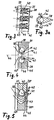
- FIG. 3 shows a detail of a segment of a bypass 31 projected into the plane.
- a plurality of circumferentially uniformly distributed ejector 38 are arranged parallel to each other, which are contoured streamlined and are flowed around by the exhaust gas in the direction of arrow 41.
- the bypass 31 is supplied to the gas to be delivered, see also Fig. 3a.
- Each mouth channel 39 is connected via two slot-shaped mouth openings 40 to the bypass; via the mouth openings 40, the gas to be supplied can flow into the bypass 31 in the direction of arrow 42.
- Each two parallel and adjacent Ejektormaschine 38 form a nozzle within the bypass 31, whose narrowest nozzle cross-section is in the region of a circular portion of the Ejektormaschine 38, extending in the flow direction of the exhaust gas tapering approximately triangular.
- the nozzle inlet cross section - the upstream side of the ejector parts - is provided with reference numeral 43, the narrowest nozzle cross section between adjacent Ejektor former with reference numeral 44 and the nozzle outlet cross section - in the region of the pointed end on the downstream side - with reference numeral 45.
- the orifices 40 are located downstream of the narrowest nozzle cross-section 44th
- the orifices 40 are located downstream of the narrowest nozzle cross-section between adjacent ejector parts 38.
- two adjacent ejector parts 38 are mirror-symmetrical with respect to a plane 46 extending in the direction of flow, whereby the mouth channel 39 In the ejector 38 limiting wall section is designed in each case circular.
- the orifices 40 are placed in such a way that the gas flowing out in the direction of arrow 42 has approximately a flow direction which is parallel to the flow direction of the exhaust gas passing in the direction of arrow 41 the narrowest nozzle cross section.
- a first ejector part 38' corresponds approximately to the embodiment according to FIG. 4 with an outlet channel 39 which opens into the bypass 31 via a mouth opening 40 downstream of the narrowest nozzle cross-section 44
- a second ejector part 38 has no orifice orifice for the supply of gas, but has a part-circular bulge 47 which is complementary to the circular portion of the adjacent ejector part 38 'in which the orifice channel 39 is located. This results in an arcuate flow channel between the adjacent ejector parts 38 '. and 38 ", whose narrowest nozzle cross-section 44 is displaced in the direction of the nozzle outlet cross-section 45.
Landscapes
- Engineering & Computer Science (AREA)
- Chemical & Material Sciences (AREA)
- Combustion & Propulsion (AREA)
- Mechanical Engineering (AREA)
- General Engineering & Computer Science (AREA)
- Chemical Kinetics & Catalysis (AREA)
- Health & Medical Sciences (AREA)
- Toxicology (AREA)
- Supercharger (AREA)
Claims (13)
- Turbocompresseur à gaz d'échappement pour un moteur à combustion interne, avec un compresseur (5) dans le tronçon d'aspiration (6) et une turbine à gaz d'échappement (3) dans le tronçon de gaz d'échappement (4), la turbine à gaz d'échappement (3) comportant dans une enveloppe de turbine (24) un espace collecteur des gaz d'échappement, dont les gaz d'échappement peuvent être amenés à la roue de la turbine (27) par l'intermédiaire d'une section transversale d'entrée de la turbine, avec une dérivation pour gaz d'échappement (31) chevauchant la section transversale d'entrée de la turbine,
caractérisé en ce que la dérivation pour gaz d'échappement (31) est conçue dans l'enveloppe de turbine (24) et relie l'espace collecteur des gaz d'échappement avec une zone de sortie (28) de la turbine à gaz d'échappement (3), et en ce que la turbine à gaz d'échappement (3) forme une pompe pour un système de transport de gaz, une conduite de transport de gaz (18, 21) associée au système de transport de gaz débouchant dans la dérivation pour gaz d'échappement (31), par l'intermédiaire d'une tubulure de raccordement (29) conçue dans l'enveloppe de turbine (24) dans laquelle est montée une canalisation de raccordement (30). - Turbocompresseur à gaz d'échappement selon la revendication 1,
caractérisé en ce qu'une buse à section transversale rétrécie est intégrée dans la dérivation pour gaz d'échappement (31) et en ce que la conduite de transport de gaz (18, 21) débouche dans la dérivation pour gaz d'échappement (31), en aval de la section transversale la plus étroite de la buse. - Turbocompresseur à gaz d'échappement selon la revendication 1 ou 2,
caractérisé en ce qu'un élément éjecteur (38) présentant un contour facilitant l'écoulement, entouré par des gaz d'échappement, comportant une bouche (40) donnant sur la dérivation pour gaz d'échappement (31) pour le gaz à alimenter est intégré dans la dérivation pour gaz d'échappement (31). - Turbocompresseur à gaz d'échappement selon la revendication 3,
caractérisé en ce qu'une bouche (40) pour le raccordement de la conduite de transport de gaz (18, 21) s'étendant à la perpendiculaire de la direction de soufflage des gaz d'échappement est conçue dans l'élément éjecteur (38) et en ce que la bouche (40) bifurque de la canalisation d'embouchure (39). - Turbocompresseur à gaz d'échappement selon la revendication 3 ou 4,
caractérisé en ce que dans la dérivation (31), l'élément éjecteur (38) présente une section transversale qui se rétrécit dans le sens d'écoulement. - Turbocompresseur à gaz d'échappement selon l'une quelconque des revendications 3 à 5,
caractérisé en ce que la dérivation (31) est répartie sous forme annulaire sur la roue de la turbine (27) et en ce qu'une pluralité d'éléments éjecteurs (38) est répartie sur la périphérie de la dérivation (31), une section transversale de buse la plus étroite (44) étant formée entre deux éléments éjecteurs voisins (38). - Turbocompresseur à gaz d'échappement selon la revendication 6,
caractérisé en ce que des éléments éjecteurs (38) de type identique sont répartis sur la périphérie. - Turbocompresseur à gaz d'échappement selon la revendication 6,
caractérisé en ce qu'au moins deux éléments éjecteurs (38) avec un contour différent sont répartis sur la périphérie, respectivement deux éléments éjecteurs voisins (38) délimitant une section transversale de buse pour les gaz d'échappement, dont l'entrée et la sortie d'écoulement vont dans des directions différentes. - Turbocompresseur à gaz d'échappement selon la revendication 8,
caractérisé en ce que les deux éléments éjecteurs (38) sont conçus sous forme convexe ou concave dans la zone de la section transversale la plus étroite de la buse (44). - Turbocompresseur à gaz d'échappement selon l'une quelconque des revendications 3 à 9,
caractérisé en ce que la bouche (40) est conçue sous la forme d'une encoche. - Turbocompresseur à gaz d'échappement selon l'une quelconque des revendications 3 à 10,
caractérisé en ce que l'orientation de la bouche (40) est approximativement parallèle à l'orientation de la section transversale de sortie de la buse (45). - Turbocompresseur à gaz d'échappement selon l'une quelconque des revendications 1 à 11 dans un moteur à combustion interne, le système de transport de gaz étant un reniflard d'aération du carter (17) et la conduite de transport de gaz (18) bifurquant du carter du vilebrequin.
- Utilisation d'un turbocompresseur à gaz d'échappement second l'une quelconque des revendications 1 à 12 dans un moteur à combustion interne, le système de transport de gaz étant un système d'injection d'air (20) et de l'air environnant pouvant être amené à la turbine de gaz échappement (3), par l'intermédiaire de la conduite de transport de gaz (18).
Applications Claiming Priority (3)
| Application Number | Priority Date | Filing Date | Title |
|---|---|---|---|
| DE10260778A DE10260778A1 (de) | 2002-12-23 | 2002-12-23 | Abgasturbolader für eine Brennkraftmaschine |
| DE10260778 | 2002-12-23 | ||
| PCT/EP2003/013071 WO2004059146A1 (fr) | 2002-12-23 | 2003-11-21 | Turbocompresseur a gaz d'echappement pour moteur a combustion |
Publications (2)
| Publication Number | Publication Date |
|---|---|
| EP1576265A1 EP1576265A1 (fr) | 2005-09-21 |
| EP1576265B1 true EP1576265B1 (fr) | 2006-04-12 |
Family
ID=32404226
Family Applications (1)
| Application Number | Title | Priority Date | Filing Date |
|---|---|---|---|
| EP03775381A Expired - Lifetime EP1576265B1 (fr) | 2002-12-23 | 2003-11-21 | Turbocompresseur a gaz d'echappement pour moteur a combustion |
Country Status (4)
| Country | Link |
|---|---|
| US (1) | US7162872B2 (fr) |
| EP (1) | EP1576265B1 (fr) |
| DE (2) | DE10260778A1 (fr) |
| WO (1) | WO2004059146A1 (fr) |
Families Citing this family (26)
| Publication number | Priority date | Publication date | Assignee | Title |
|---|---|---|---|---|
| SE524780C2 (sv) * | 2003-02-27 | 2004-10-05 | Volvo Lastvagnar Ab | Förbränningsmotor med turboaggregat |
| US7154931B2 (en) * | 2004-06-22 | 2006-12-26 | Ksy Corporation | Laser with Brayton cycle outlet pump |
| DE102005020482A1 (de) * | 2005-04-29 | 2006-11-09 | Mahle International Gmbh | Brennkraftmaschine mit Abgasrückführung |
| SE529167C2 (sv) * | 2005-06-15 | 2007-05-22 | Volvo Lastvagnar Ab | Vevhusventilation |
| FR2891011A1 (fr) * | 2005-09-21 | 2007-03-23 | Melchior Jean F | Dispositif de suralimentation pour moteur a combustion interne, et vehicule automobile equipe d'un tel dispositif |
| DE102005046507A1 (de) * | 2005-09-29 | 2007-04-05 | Daimlerchrysler Ag | Brennkraftmaschine mit zwei hintereinander geschalteten Abgasturboladern |
| DE102007046667A1 (de) * | 2007-09-27 | 2009-04-09 | Behr Gmbh & Co. Kg | Mehrstufige Aufladegruppe, Mehrstufige Aufladevorrichtung und Aufladesystem |
| EP2272747B1 (fr) * | 2008-04-01 | 2019-05-08 | National Institute of Maritime, Port and Aviation Technology | Dispositif de réduction de résistance de frottement pour bateau |
| US8061974B2 (en) * | 2008-09-11 | 2011-11-22 | Honeywell International Inc. | Compressor with variable-geometry ported shroud |
| US8966897B2 (en) * | 2009-02-26 | 2015-03-03 | Borgwarner Inc. | Internal combustion engine |
| US9039353B2 (en) * | 2009-07-02 | 2015-05-26 | Borgwarner Inc. | Turbocharger turbine |
| US8424304B2 (en) * | 2009-11-03 | 2013-04-23 | Honeywell International Inc. | Turbine assembly for a turbocharger, having two asymmetric volutes that are sequentially activated, and associated method |
| DE102012112396A1 (de) * | 2012-12-17 | 2014-07-03 | Ihi Charging Systems International Gmbh | Abgasführungsabschnitt für eine Turbine und Verfahren zur Regelung einer Turbine |
| DE102013219329B4 (de) * | 2013-09-25 | 2022-12-08 | Volkswagen Aktiengesellschaft | Turbinenanordnung für eine Brennkraftmaschine und aufladbare Brennkraftmaschine |
| DE102015207573B4 (de) * | 2015-04-24 | 2023-07-06 | Ford Global Technologies, Llc | Brennkraftmaschine mit kombiniertem Abgasnachbehandlungssystem |
| US9739166B1 (en) | 2016-08-31 | 2017-08-22 | Borgwarner Inc. | VTG internal by-pass |
| DE102016119255A1 (de) * | 2016-10-10 | 2018-04-12 | Ihi Charging Systems International Gmbh | Abgasführungsabschnitt für einen Abgasturbolader und Abgasstrang für eine Verbrennungskraftmaschine sowie Verfahren zum Betreiben eines Abgasturboladers |
| US10985608B2 (en) | 2016-12-13 | 2021-04-20 | General Electric Company | Back-up power system for a component and method of assembling same |
| DE102019106682B4 (de) * | 2019-03-15 | 2022-07-07 | Bürkert Werke GmbH & Co. KG | Druckregler |
| JP7303763B2 (ja) * | 2020-02-28 | 2023-07-05 | 三菱重工マリンマシナリ株式会社 | 排気ディフューザ及びタービンハウジング、並びに過給機 |
| FR3114125A1 (fr) * | 2020-09-17 | 2022-03-18 | Psa Automobiles Sa | Moteur a injection d’air a l’echappement |
| DE102020007366B4 (de) * | 2020-12-03 | 2023-12-14 | Mercedes-Benz Group AG | Verbrennungskraftmaschine für ein Kraftfahrzeug, insbesondere für einen Kraftwagen, sowie Kraftfahrzeug |
| FR3122212B1 (fr) * | 2021-04-21 | 2023-11-24 | Psa Automobiles Sa | Moteur a combustion interne equipe d’un dispositif d’injection d’air a l’echappement |
| US11680501B2 (en) * | 2021-09-21 | 2023-06-20 | Deere & Company | Internal combustion engine and crankcase ventilation system |
| DE102022117716B3 (de) * | 2022-07-15 | 2023-06-07 | Dr. Ing. H.C. F. Porsche Aktiengesellschaft | Abgassystem einer Brennkraftmaschine |
| DE112023002623T5 (de) * | 2022-09-07 | 2025-04-10 | Ihi Corporation | Turbine |
Family Cites Families (20)
| Publication number | Priority date | Publication date | Assignee | Title |
|---|---|---|---|---|
| US1531080A (en) * | 1925-03-24 | Telephone-exchange system | ||
| US2366365A (en) * | 1942-02-09 | 1945-01-02 | Ford Motor Co | Supercharger |
| GB1531080A (en) * | 1977-08-26 | 1978-11-01 | Gec Diesels Ltd | Crankcase ventilation of internal combustion piston engines |
| JPS5525505A (en) * | 1978-08-10 | 1980-02-23 | Ishikawajima Harima Heavy Ind Co Ltd | Supercharger provided on turbine outlet with ejector |
| DE2939152C2 (de) * | 1979-09-27 | 1983-10-20 | Bayerische Motoren Werke AG, 8000 München | Turbine eines Abgasturboladers für Brennkraftmaschinen |
| JPS5683517A (en) * | 1979-12-12 | 1981-07-08 | Hitachi Ltd | Radial flow turbine for exhaust turbine supercharger |
| JPS57124023A (en) * | 1981-01-26 | 1982-08-02 | Mazda Motor Corp | Secondary air feeder for multicylinder engine with supercharger |
| JPS618421A (ja) * | 1984-06-22 | 1986-01-16 | Toyota Motor Corp | タ−ボチヤ−ジヤの排気バイパス装置 |
| DE3606944A1 (de) * | 1986-03-04 | 1987-09-10 | Audi Ag | Abgasturbolader |
| DE4312078C2 (de) * | 1993-04-13 | 1995-06-01 | Daimler Benz Ag | Abgasturbolader für eine aufgeladene Brennkraftmaschine |
| DE19540060A1 (de) * | 1995-10-27 | 1997-04-30 | Daimler Benz Ag | Motorbremsvorrichtung |
| DE19618160C2 (de) * | 1996-05-07 | 1999-10-21 | Daimler Chrysler Ag | Abgasturbolader für eine Brennkraftmaschine |
| DE19651498C1 (de) * | 1996-12-11 | 1998-04-16 | Daimler Benz Ag | Abgasturboladerturbine für eine Brennkraftmaschine |
| US6123061A (en) * | 1997-02-25 | 2000-09-26 | Cummins Engine Company, Inc. | Crankcase ventilation system |
| JP2893396B2 (ja) | 1997-09-01 | 1999-05-17 | 株式会社東京機械製作所 | 紙票添付装置 |
| DE19836677C2 (de) * | 1998-08-13 | 2001-04-19 | Daimler Chrysler Ag | Motorbremseinrichtung für eine Brennkraftmaschine mit einem Abgasturbolader |
| US6202413B1 (en) * | 1999-02-04 | 2001-03-20 | Cummins Engine Company, Inc. | Multiple nozzle ejector for wastegated turbomachinery |
| JP2000274254A (ja) * | 1999-03-24 | 2000-10-03 | Hitachi Ltd | ターボチャージャ |
| US6276139B1 (en) * | 2000-03-16 | 2001-08-21 | Ford Global Technologies, Inc. | Automotive engine with controlled exhaust temperature and oxygen concentration |
| US6767185B2 (en) * | 2002-10-11 | 2004-07-27 | Honeywell International Inc. | Turbine efficiency tailoring |
-
2002
- 2002-12-23 DE DE10260778A patent/DE10260778A1/de not_active Withdrawn
-
2003
- 2003-11-21 EP EP03775381A patent/EP1576265B1/fr not_active Expired - Lifetime
- 2003-11-21 WO PCT/EP2003/013071 patent/WO2004059146A1/fr not_active Ceased
- 2003-11-21 DE DE50302991T patent/DE50302991D1/de not_active Expired - Lifetime
-
2005
- 2005-06-22 US US11/159,391 patent/US7162872B2/en not_active Expired - Fee Related
Also Published As
| Publication number | Publication date |
|---|---|
| DE10260778A1 (de) | 2004-07-01 |
| US20050252211A1 (en) | 2005-11-17 |
| DE50302991D1 (de) | 2006-05-24 |
| US7162872B2 (en) | 2007-01-16 |
| EP1576265A1 (fr) | 2005-09-21 |
| WO2004059146A1 (fr) | 2004-07-15 |
Similar Documents
| Publication | Publication Date | Title |
|---|---|---|
| EP1576265B1 (fr) | Turbocompresseur a gaz d'echappement pour moteur a combustion | |
| EP1316699B1 (fr) | Turbocompresseur pour moteur à combustion interne et méthode de fonctionnement d'un moteur à combustion interne turbocompressé | |
| DE4312078C2 (de) | Abgasturbolader für eine aufgeladene Brennkraftmaschine | |
| DE60117448T2 (de) | Venturi-Bypass eines Abgasrückführungssystems | |
| DE112011102931B4 (de) | Kompressorrückführung in ringförmiges Volumen | |
| DE10116643C2 (de) | Hubkolbenbrennkraftmaschine | |
| DE112006000420B4 (de) | Ladedruckwastegateeinrichtung zur Abgasrückführungsunterstützung | |
| WO2007093367A1 (fr) | Compresseur pour moteur a combustion interne | |
| EP2025896A2 (fr) | Compresseur radial pour turbocompresseur | |
| EP3141735B1 (fr) | Moteur à combustion interne comprenant un survolteur | |
| DE10054601A1 (de) | Einleitungsventurimittel für ein Abgaszirkulationssystem in einem Verbrennungsmotor | |
| WO2009018887A1 (fr) | Turbocompresseur à gaz d'échappement pour un moteur à combustion interne à pistons alternatifs | |
| DE3529280C1 (de) | Vorrichtung zur Erhoehung der Drehzahl eines Abgasturboladers an einer Brennkraftmaschine | |
| WO2005001257A1 (fr) | Moteur a combustion interne comportant un compresseur dans la pipe d'admission et procede correspondant | |
| DE10343756B4 (de) | Lufteinlasskühlsystem und -verfahren | |
| WO2006117073A1 (fr) | Turbocompresseur a gaz d'echappement pour moteur a combustion interne | |
| DE102004049218A1 (de) | Brennkraftmaschine mit Abgasrückführungseinrichtung | |
| DE102009041223B4 (de) | Verfahren zum Auslegen eines Antriebssystems | |
| EP4405574B1 (fr) | Moteur à combustion interne pour un véhicule automobile, en particulier pour une voiture | |
| EP1619365B1 (fr) | Post-traitement des gaz d'échappement avec suralimentation séquentielle | |
| DE10232519A1 (de) | Abgasturbolader für eine Brennkraftmaschine | |
| EP2602468B1 (fr) | Moteur à combustion interne avec système de recirculation de gaz d'échappement | |
| DE10226694A1 (de) | Aufgeladene Brennkraftmaschine mit einer Kurbelgehäuseentlüftungseinrichtung | |
| DE102007021934A1 (de) | Ladervorrichtung für eine Brennkraftmaschine sowie Brennkraftmaschine | |
| DE10260779A1 (de) | Abgasturbolader |
Legal Events
| Date | Code | Title | Description |
|---|---|---|---|
| PUAI | Public reference made under article 153(3) epc to a published international application that has entered the european phase |
Free format text: ORIGINAL CODE: 0009012 |
|
| 17P | Request for examination filed |
Effective date: 20050518 |
|
| AK | Designated contracting states |
Kind code of ref document: A1 Designated state(s): AT BE BG CH CY CZ DE DK EE ES FI FR GB GR HU IE IT LI LU MC NL PT RO SE SI SK TR |
|
| GRAP | Despatch of communication of intention to grant a patent |
Free format text: ORIGINAL CODE: EPIDOSNIGR1 |
|
| RIN1 | Information on inventor provided before grant (corrected) |
Inventor name: SCHMID, WOLFRAM Inventor name: SUMSER, SIEGFRIED |
|
| GRAS | Grant fee paid |
Free format text: ORIGINAL CODE: EPIDOSNIGR3 |
|
| GRAA | (expected) grant |
Free format text: ORIGINAL CODE: 0009210 |
|
| AK | Designated contracting states |
Kind code of ref document: B1 Designated state(s): DE FR GB IT |
|
| PG25 | Lapsed in a contracting state [announced via postgrant information from national office to epo] |
Ref country code: IT Free format text: LAPSE BECAUSE OF FAILURE TO SUBMIT A TRANSLATION OF THE DESCRIPTION OR TO PAY THE FEE WITHIN THE PRESCRIBED TIME-LIMIT;WARNING: LAPSES OF ITALIAN PATENTS WITH EFFECTIVE DATE BEFORE 2007 MAY HAVE OCCURRED AT ANY TIME BEFORE 2007. THE CORRECT EFFECTIVE DATE MAY BE DIFFERENT FROM THE ONE RECORDED. Effective date: 20060412 |
|
| RBV | Designated contracting states (corrected) |
Designated state(s): DE FR GB IT |
|
| REG | Reference to a national code |
Ref country code: GB Ref legal event code: FG4D Free format text: NOT ENGLISH |
|
| GBT | Gb: translation of ep patent filed (gb section 77(6)(a)/1977) |
Effective date: 20060412 |
|
| REF | Corresponds to: |
Ref document number: 50302991 Country of ref document: DE Date of ref document: 20060524 Kind code of ref document: P |
|
| ET | Fr: translation filed | ||
| PLBE | No opposition filed within time limit |
Free format text: ORIGINAL CODE: 0009261 |
|
| STAA | Information on the status of an ep patent application or granted ep patent |
Free format text: STATUS: NO OPPOSITION FILED WITHIN TIME LIMIT |
|
| 26N | No opposition filed |
Effective date: 20070115 |
|
| REG | Reference to a national code |
Ref country code: FR Ref legal event code: CA Ref country code: FR Ref legal event code: CD |
|
| PGFP | Annual fee paid to national office [announced via postgrant information from national office to epo] |
Ref country code: FR Payment date: 20100603 Year of fee payment: 7 |
|
| PGFP | Annual fee paid to national office [announced via postgrant information from national office to epo] |
Ref country code: DE Payment date: 20100511 Year of fee payment: 7 Ref country code: IT Payment date: 20100430 Year of fee payment: 7 |
|
| PGFP | Annual fee paid to national office [announced via postgrant information from national office to epo] |
Ref country code: GB Payment date: 20100423 Year of fee payment: 7 |
|
| GBPC | Gb: european patent ceased through non-payment of renewal fee |
Effective date: 20101121 |
|
| REG | Reference to a national code |
Ref country code: FR Ref legal event code: ST Effective date: 20110801 |
|
| REG | Reference to a national code |
Ref country code: DE Ref legal event code: R119 Ref document number: 50302991 Country of ref document: DE Effective date: 20110601 Ref country code: DE Ref legal event code: R119 Ref document number: 50302991 Country of ref document: DE Effective date: 20110531 |
|
| PG25 | Lapsed in a contracting state [announced via postgrant information from national office to epo] |
Ref country code: FR Free format text: LAPSE BECAUSE OF NON-PAYMENT OF DUE FEES Effective date: 20101130 |
|
| PG25 | Lapsed in a contracting state [announced via postgrant information from national office to epo] |
Ref country code: GB Free format text: LAPSE BECAUSE OF NON-PAYMENT OF DUE FEES Effective date: 20101121 |
|
| PG25 | Lapsed in a contracting state [announced via postgrant information from national office to epo] |
Ref country code: IT Free format text: LAPSE BECAUSE OF NON-PAYMENT OF DUE FEES Effective date: 20101121 |
|
| PG25 | Lapsed in a contracting state [announced via postgrant information from national office to epo] |
Ref country code: DE Free format text: LAPSE BECAUSE OF NON-PAYMENT OF DUE FEES Effective date: 20110531 |