EP1576246B1 - Dispositif de verrouillage - Google Patents
Dispositif de verrouillage Download PDFInfo
- Publication number
- EP1576246B1 EP1576246B1 EP03813512A EP03813512A EP1576246B1 EP 1576246 B1 EP1576246 B1 EP 1576246B1 EP 03813512 A EP03813512 A EP 03813512A EP 03813512 A EP03813512 A EP 03813512A EP 1576246 B1 EP1576246 B1 EP 1576246B1
- Authority
- EP
- European Patent Office
- Prior art keywords
- coupling
- locking device
- rotor
- drive
- coupling element
- Prior art date
- Legal status (The legal status is an assumption and is not a legal conclusion. Google has not performed a legal analysis and makes no representation as to the accuracy of the status listed.)
- Expired - Lifetime
Links
- 230000008878 coupling Effects 0.000 claims abstract description 222
- 238000010168 coupling process Methods 0.000 claims abstract description 222
- 238000005859 coupling reaction Methods 0.000 claims abstract description 222
- 230000033001 locomotion Effects 0.000 claims abstract description 14
- 230000000903 blocking effect Effects 0.000 claims description 25
- 230000000694 effects Effects 0.000 claims description 11
- 230000009471 action Effects 0.000 claims description 7
- 230000007704 transition Effects 0.000 claims description 5
- 239000000463 material Substances 0.000 claims description 3
- 230000005294 ferromagnetic effect Effects 0.000 claims 1
- 230000005291 magnetic effect Effects 0.000 description 8
- 238000004891 communication Methods 0.000 description 6
- 230000035939 shock Effects 0.000 description 5
- 238000013459 approach Methods 0.000 description 4
- 239000003302 ferromagnetic material Substances 0.000 description 4
- 230000007246 mechanism Effects 0.000 description 4
- 230000005540 biological transmission Effects 0.000 description 3
- 239000002655 kraft paper Substances 0.000 description 3
- 238000010008 shearing Methods 0.000 description 3
- XEEYBQQBJWHFJM-UHFFFAOYSA-N Iron Chemical compound [Fe] XEEYBQQBJWHFJM-UHFFFAOYSA-N 0.000 description 2
- PXHVJJICTQNCMI-UHFFFAOYSA-N Nickel Chemical compound [Ni] PXHVJJICTQNCMI-UHFFFAOYSA-N 0.000 description 2
- 238000013475 authorization Methods 0.000 description 2
- 230000008901 benefit Effects 0.000 description 2
- 239000007822 coupling agent Substances 0.000 description 2
- 238000010586 diagram Methods 0.000 description 2
- 230000005484 gravity Effects 0.000 description 2
- 239000000696 magnetic material Substances 0.000 description 2
- 230000003213 activating effect Effects 0.000 description 1
- 238000004026 adhesive bonding Methods 0.000 description 1
- 230000001070 adhesive effect Effects 0.000 description 1
- 230000004888 barrier function Effects 0.000 description 1
- 230000008094 contradictory effect Effects 0.000 description 1
- 238000013461 design Methods 0.000 description 1
- 230000005674 electromagnetic induction Effects 0.000 description 1
- 230000005670 electromagnetic radiation Effects 0.000 description 1
- 230000005284 excitation Effects 0.000 description 1
- 230000005333 ferromagnetic domain Effects 0.000 description 1
- 238000009434 installation Methods 0.000 description 1
- 229910052742 iron Inorganic materials 0.000 description 1
- 238000000034 method Methods 0.000 description 1
- 230000007935 neutral effect Effects 0.000 description 1
- 229910052759 nickel Inorganic materials 0.000 description 1
- 230000003716 rejuvenation Effects 0.000 description 1
- 230000001360 synchronised effect Effects 0.000 description 1
- 238000012360 testing method Methods 0.000 description 1
Images


Classifications
-
- E—FIXED CONSTRUCTIONS
- E05—LOCKS; KEYS; WINDOW OR DOOR FITTINGS; SAFES
- E05B—LOCKS; ACCESSORIES THEREFOR; HANDCUFFS
- E05B47/00—Operating or controlling locks or other fastening devices by electric or magnetic means
- E05B47/06—Controlling mechanically-operated bolts by electro-magnetically-operated detents
- E05B47/0611—Cylinder locks with electromagnetic control
- E05B47/0638—Cylinder locks with electromagnetic control by disconnecting the rotor
- E05B47/0646—Cylinder locks with electromagnetic control by disconnecting the rotor radially
- E05B47/0649—Cylinder locks with electromagnetic control by disconnecting the rotor radially with a rectilinearly moveable coupling element
-
- E—FIXED CONSTRUCTIONS
- E05—LOCKS; KEYS; WINDOW OR DOOR FITTINGS; SAFES
- E05B—LOCKS; ACCESSORIES THEREFOR; HANDCUFFS
- E05B17/00—Accessories in connection with locks
- E05B17/04—Devices for coupling the turning cylinder of a single or a double cylinder lock with the bolt operating member
-
- E—FIXED CONSTRUCTIONS
- E05—LOCKS; KEYS; WINDOW OR DOOR FITTINGS; SAFES
- E05B—LOCKS; ACCESSORIES THEREFOR; HANDCUFFS
- E05B47/00—Operating or controlling locks or other fastening devices by electric or magnetic means
- E05B47/0001—Operating or controlling locks or other fastening devices by electric or magnetic means with electric actuators; Constructional features thereof
- E05B2047/0014—Constructional features of actuators or power transmissions therefor
- E05B2047/0018—Details of actuator transmissions
- E05B2047/0023—Nuts or nut-like elements moving along a driven threaded axle
-
- E—FIXED CONSTRUCTIONS
- E05—LOCKS; KEYS; WINDOW OR DOOR FITTINGS; SAFES
- E05B—LOCKS; ACCESSORIES THEREFOR; HANDCUFFS
- E05B47/00—Operating or controlling locks or other fastening devices by electric or magnetic means
- E05B47/0001—Operating or controlling locks or other fastening devices by electric or magnetic means with electric actuators; Constructional features thereof
- E05B2047/0014—Constructional features of actuators or power transmissions therefor
- E05B2047/0018—Details of actuator transmissions
- E05B2047/0026—Clutches, couplings or braking arrangements
-
- E—FIXED CONSTRUCTIONS
- E05—LOCKS; KEYS; WINDOW OR DOOR FITTINGS; SAFES
- E05B—LOCKS; ACCESSORIES THEREFOR; HANDCUFFS
- E05B47/00—Operating or controlling locks or other fastening devices by electric or magnetic means
- E05B47/0001—Operating or controlling locks or other fastening devices by electric or magnetic means with electric actuators; Constructional features thereof
- E05B47/0012—Operating or controlling locks or other fastening devices by electric or magnetic means with electric actuators; Constructional features thereof with rotary electromotors
-
- Y—GENERAL TAGGING OF NEW TECHNOLOGICAL DEVELOPMENTS; GENERAL TAGGING OF CROSS-SECTIONAL TECHNOLOGIES SPANNING OVER SEVERAL SECTIONS OF THE IPC; TECHNICAL SUBJECTS COVERED BY FORMER USPC CROSS-REFERENCE ART COLLECTIONS [XRACs] AND DIGESTS
- Y10—TECHNICAL SUBJECTS COVERED BY FORMER USPC
- Y10T—TECHNICAL SUBJECTS COVERED BY FORMER US CLASSIFICATION
- Y10T70/00—Locks
- Y10T70/70—Operating mechanism
- Y10T70/7051—Using a powered device [e.g., motor]
- Y10T70/7062—Electrical type [e.g., solenoid]
- Y10T70/7102—And details of blocking system [e.g., linkage, latch, pawl, spring]
Definitions
- the invention relates to a locking device for a locking system.
- Locking system is understood here to mean a system with mechanical elements which allows or blocks access to or access to an object, depending on whether or not there is authorization.
- a locking device will in particular enable or prevent the operation of a lock cylinder or lock by rotation of a key or a door knob, by operating a door handle or similar means, or automated, by means of suitable drive means, etc.
- Locking devices with mechanically and electronically - mechatronically controlled locking elements are known. They have all the properties of conventional purely mechanical locking devices. The additional electronically controlled locking also provides the option of individually activating and locking keys. With mechatronic locking devices so additional flexibility in the Schliessorganisation can be achieved.
- the electronically controlled locking is based on a data transmission between a key-side electronic module and a lock-side electronic module.
- This data transmission can be by touch - eg. By means of electrical contacts on key and lock - or non-contact - eg. By electromagnetic induction - take place.
- Data can be transmitted in one or both directions.
- a lock-side motor is activated, which electronically controls a locking element moves such that it releases the lock cylinder or the lock.
- Such a locking device is known, for example, from International Publication WO 98/28508 or from International Publication WO 01/21913.
- a disadvantage of such locking devices according to the prior art is that it is sufficient in tampering attempts to overcome the barrier caused by the locking element of the lock cylinder. This can be done by shock, by vibration, by brute force or otherwise.
- the object of the invention is therefore to provide a mechatronic locking device which against external foreign influences, in particular against violent. Vibratory and / or shock or magnetic effects, is resistant and ensures safe functioning.
- the locking device has a coupling element and an output element which can be brought into operative connection with locking means. It can be brought into a first and a second clutch state by means of electronically controlled drive means via drive means which move the clutch element.
- the rotor - that is, the lock-rotatable member by key, door handle or similar means - is decoupled from the output member in the sense that there is no direct coupling via the coupling member or other coupling means which would cause rotation of the rotor causes a movement of the output element.
- the coupling element couples the output element with a rotor which can be actuated by key, door handle, doorknob or a similar means or by an electric drive.
- the approach according to the invention therefore differs from the prior art in that it is not simply necessary to decouple the rotor and the housing, but rather that The output element must be coupled to the rotor - and possibly also decoupled from the housing.
- the coupling element or blocking element can be deflected from its rest position, for example by means of bumps.
- this is exploited by being manipulated by a plurality of bumps until the locking element is in the free position.
- the locking device is influenced so that the once located in the free-standing blocking element is fixed immediately in this - for example, by a constant acting on the rotor torque.
- the mechanical decoupling of the rotor and output element in the first coupling state also has the advantage that even by violent rotation of the rotor, the lock can not be operated: The rotor rotates at most empty.
- the output element in the first coupling state, is blocked with respect to a housing. Thus it is additionally locked against rotation.
- the coupling element may have an at least partially spherical surface - and be formed for example as a ball. This minimizes the number of positions in which it engages - which is advantageous as described above. There is then the requirement that a shear lines between the elements to be coupled and the equator of the coupling element are aligned. When the equator of the coupling element is above or below the shear line, the coupling element is pushed away from the coupling layer by exerting force on one of the elements to be coupled.
- the coupling element is neither coupled to the housing nor to the rotor.
- the coupling element can then be rotated in its second coupling position during a rotational movement of the rotor. It is, for example, in an opening which is formed by recesses in the rotor and the output element.
- Even if the coupling element is always mitFE with the output element, but it is a mechanically independent element. It can be provided that before the removal of the key, the rotor must be returned to its original orientation, so it can only be rotated by integer turns.
- the drive means can, for example, the coupling element between two coupling layers - according to the two coupling states - move: In the first coupling position, the coupling element couples the housing and driven element, while it causes no coupling between the rotor and the driven element. In the second coupling position, it couples the rotor and the output element, but does not cause any coupling between the housing and the output element.
- the coupling element serves as a blocking element propulsion means of the drive means obstruct the output member in the first coupling state relative to the housing.
- the coupling element couples rotor and output sleeve.
- blocking element and coupling element are designed and arranged so that the blocking element, when it is moved from the second to the first coupling state, at the same time by direct or indirect action, the coupling element moves away from the coupling position.
- Another alternative provides that the output element is not blocked against the housing in the first coupling state.
- the output element is, for example, firmly connected to an inner door handle.
- this direct coupling between output element and inner door handle also provides some protection against manipulation - after all, the inner door handle must be moved with each manipulation attempt.
- an electric motor can be used with a lifting spindle.
- Electric motors are relatively economical power consumers compared to magnetic actuators. In addition, they are due to the design largely vibration, shock and magnetic resistant.
- the coupling element can be displaceable by the drive means, quasi-positively guided ⁇ or even completely positively guided. This means that the position of the coupling element between the first and the second clutch layer is defined at all times by the drive means, for example by being connected to the drive means of the drive means.
- this connection can be solved only by a certain amount of force; it may be, for example, that the propulsion means and / or the Kupplungselment has a permanent magnetic moment and thereby the coupling element adheres to the propulsion medium.
- the connection is so strong that it is not solvable by normal bumps.
- the coupling element is fixed by mechanical connections on the propulsion medium; The mechanical connections are, for example, solved as soon as the coupling agent is in the second coupling position.
- the locking device can thus be designed so that the coupling element is always on one of two predetermined paths: on the first path quasi-positively guided or positively guided between the first and the second clutch position, and rotated on the second path through the rotor and relative to in a constant position about an axis of the rotor.
- the drive means may be provided with spring means which are designed and arranged such that the coupling element located between the first coupling position and the second coupling position can be moved by mechanical action counter to a spring force in the direction of the first coupling position. This can prevent damage caused by violent manipulation attempts and failure of the drive.
- the coupling element When the coupling element is in an undefined position between the first and second coupling layers, and force is applied to a shear line, the coupling element deviates toward the first coupling layer without causing any damage.
- Locking device may - in the event that it is used with a lock cylinder - have a key blocking element which is movable by inserting the key in the key opening from a first position to a second position, wherein it in the second position, a withdrawal of the key only at certain, predetermined orientations of the rotor allowed.
- this allows the user to open a door in a manner known per se by pulling on the key which is not oriented vertically.
- it can be ensured that the system is always in a defined position with the key removed, in which the coupling element between the two coupling layers is displaceable.
- the key blocking element blocks the rotor in the first position against rotation so that it can not be moved away from its defined position by a screwdriver or similar means or by randomly induced movements.
- the Belleblockerelement is damaged at best, because of the mechanical decoupling of rotor and housing but never the essential elements for operating the bolt elements.
- the key blocking element may be, for example, a rocker arm which is connected to a spring which causes a restoring force to the first position.
- the additional security which is caused by the above elements, has the consequence that the locking device, for example, manages without purely mechanically actuated tumblers.
- This can be a locking device according to the invention with any existing locking systems combined and used across plants.
- the locking device allows a connection of multiple systems and a deployment in multiple systems with a system-neutral key.
- a locking device according to the invention may, however, additionally also have mechanical tumblers.
- the inventive locking device is thus system neutral in this embodiment: mechanical and mechantronic system components are completely separable.
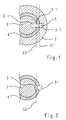
- FIG. Very schematically are a rotatable by a key rotor 2 and connected to a. For example, directly into a door housing connected and therefore not rotatable stator 3. Between the rotor 2 and stator 3 is designed as a drive output shaft output element 4. This is at least partially the axis of rotation of the rotor is rotatable and can be brought into operative connection with a driver, which is designed for actuating locking elements, so that the bolt - if necessary, if certain conditions are met - by turning of the output element 4 can be actuated.
- a driver which is designed for actuating locking elements
- Both the rotor and the stator each have a recess 2.1, 3.1, which are aligned in the drawn arrangement with a recess 4.1 in the output element.
- a coupling element 5 is located in the opening formed by these recesses.
- the coupling element 5 ball is formed. But it could also have a different shape and be, for example, a pin with a partially spherical surface or a pin.
- the operating principle is the following:
- the coupling element is displaceable by means not shown drive means of the opening. It assumes a first coupling position - or blocking position - when it is on the shear line S1, which is formed between the stator 3 and the output element. This state corresponds to the first coupling state.
- the Kupplugselement couples the output element with the stator. It prevents rotation of the output element and thus actuation of the bolt. But the coupling element does not cause a coupling between the rotor and the driven element when it is in the first coupling position. Rotor and output element and thus also rotor and bolt are thus decoupled when the coupling element is in the locked position. This is a difference from the prior art, where blocking is effected by locking the rotor to the stator.
- the arrangement shown in the figure is an example of a locking device with a coupling element 5, which is electronically controlled between a first and a second coupling position - according to the first and second coupling state -verschiebbar, wherein the coupling element 5, 5 ⁇ in a first coupling position the Output element 4 with respect to the housing blocks and in a second clutch position the output member 4 couples with the rotor 2, wherein the rotor 2 is not coupled to the output member 4 when the clutch member is in its first clutch position.
- Figure 2 shows a variant of the principle shown in Figure 1, where the coupling element 5 'is not spherical, but has a partially spherical surface.
- the recess 2.1 in the rotor is in this embodiment, for example. Limited so that the coupling element the rotor 2 and the output element 4 only couples when it is inserted into the opening to the stop. If the coupling element withdrawn slightly, it is pushed back at a torque on the rotor due to its partially spherical surface in the direction of its first coupling position.
- the hemispherical surface portion of Figure 2 may also be provided another surface shape which causes such a recoil - for example, a conical shape, etc.
- the actually to be met in this embodiment condition is that the shape of the coupling element is such that it has an area in which it is constantly rejuvenated.
- the depth of the recess 2.1 is limited in the rotor so that the coupling element in its second coupling position is also at a stop or almost at a stop, also be present in a spherical coupling element.
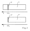
- FIG. 3 very schematically illustrates the set of all states 11.
- the coupling element is guided through the recesses and is displaceable in only one direction x; the states can therefore be characterized by the position in this direction x.
- the upper diagram of the figure shows the situation for the arrangement according to FIG. 1.
- the subset of those states in which the coupling element is in its second coupling position and enables the opening of the lock is provided with the reference numeral 12 in the FIGURE. Due to the spherical surface of the coupling element its position must be chosen very precisely so that its equator is on the shear line S2. Otherwise, the coupling element is pushed away in one or the other direction with a torque acting on the rotor. This fact has the effect that the subset 12 of the states in which release takes place is very small. With random movements, the probability almost disappears that the coupling element in the release position (the second clutch position) gets.
- the lower diagram of Figure 3 relates to the structure according to Figure 2. This differs from that of Figure 1, characterized in that the Kupplungselelement is also in its second coupling position on a stop.
- the subset 12 of the states in which a release takes place is therefore entered completely at the edge. Also in this case, it is small in comparison to the amount of all states, since the coupling element is also pushed away from the coupling position with a torque on the rotor, if it is not positioned exactly in the Kupplunslage.
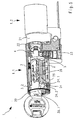
- the cylinder lock partially shown in Figures 4 and 5 has a double lock cylinder 1 with a first, provided for a door outside part cylinder 1.1 and a second, provided for a door inside partial cylinder 1.2 (optional).
- the second partial cylinder 1.2 is shown only schematically in the figure.
- the first partial cylinder 1.1 has a rotor 2 and a stator 3 surrounding it.
- the rotor is provided with a key opening 2.2.
- the driver 21 can be coupled in a manner yet darloom via a to be inserted by inserting a key 30 wing member 22 via the output member 4;
- An analogous device can also be provided for the possibly existing second partial cylinder 1.2.
- the wing element 22 is mechanically coupled to an output element 4. This can be coupled in the manner already explained either with housing parts or the stator 3 or with the rotor.
- the serving for this purpose coupling element 5 is spherical in the example shown.
- the coupling element is displaceable by drive means 23 between the first coupling layer (FIG. 4) and the second coupling layer (FIG. 5). In the first coupling position, the equator of the coupling element is located on the shearing line between the output element and the stator, in the second coupling position on the shearing line between the output element and the rotor.
- the drive means are electronically controlled.
- the cylinder lock has a not-shown electronic module and communication means for communication with a data carrier of the key 30.
- the communication means for the communication between the data carrier and electronic module can be formed in a conventional manner for non-contact communication via electromagnetic radiation, or the key can Also have contacts that are contactable via pins of the cylinder lock. Other communication options are conceivable.
- the electronic module determines - for example, also in a conventional manner - by means of data exchanged with the data medium of the key, whether the key authorizes access to the locked object. With an authorization, the electronic module controls the drive means so that they bring the coupling element in the second coupling position and release the lock ( Figure 5).
- the key holder can then cause a rotation of the output element 4 with a rotation of the key, with the coupling element in the opening, which form through recesses 2.1, 4.1 of the rotor and the output element rotates.
- the output element 4 causes via wing element 22 and driver 21 an actuation of Riegelemententen.
- movable key blocking element 24 is shown. This is mounted in the figure by a pivot pin 25 on the rotor 2 and is held with spring means 26 in its first position when no further forces act. In the first position, it blocks the rotor 2 by standing against the stator 3 in a standard orientation against rotations. By inserting a key, it can be brought into its second position against the spring force. As a result, the blocking of the rotor is released, and this can be freely rotated.
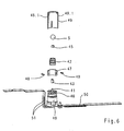
- the drive means 23 has an electric motor 40 through which a drive shaft 41 can be rotated.
- a lifting spindle 42 is placed linearly displaceable along this.
- Zwischiteil 43 is still drawn.
- Mounted on the electric motor 40 with a spring 46 is a Votriebshülse 47 with projecting through slots of the drive sleeve in bobnuten the Hubspindel 42 guide elements 48.
- the electric motor with the lifting spindle 42 and the propulsion sleeve 47 are of a bearing sleeve 49th surrounded and held.
- the spring 46 presses the propulsion sleeve 47 against a stop surface 49.1 of the bearing sleeve.
- propulsion acts on the jackscrew 42 due to the guide elements 48 projecting into the helical grooves.
- the jackscrew may be moved between a first, retracted position and a second position, in FIG For example, it protrudes partially from the bearing sleeve and the propulsion sleeve 47.
- the coupling element 5 is guided guided between its first and its second clutch position. If on the coupling element, a force in the direction of its first coupling position - ie in the figure against the bottom - so soft coupling element 5, lifting spindle 42 and propulsion sleeve 47 due to the action of the spring 46 against the spring force down.
- a force may be due to a torque acting on the rotor, if it acts when the coupling element between the two coupling layers.
- power supply cables 51 for electronically controlled energization of the electric motor as well as a base plate 50 carrying these and possibly electronic information transmission channels.
- the mechanism described here for exerting a propulsion is not the only possible way of electronically controlling propulsion.
- the skilled person will recognize many other ways in which a rotary motion of an electric motor is translated into a propulsion movement, for example, as in the present case by means of a screw gear. Variants without electric motor are also conceivable, for example a magnetic actuator.
- the role of the permanent magnet 45 will be briefly explained.
- the ferromagnetic domains in the ferromagnetic material form so that the magnetic field in the transition between the magnetized body and the ferromagnetic material is continuous. If the material and the body are separated by even a short distance, such a steady course is no longer possible, so energy must be expended to separate material and body. This causes something like a, Klebrial ', this is known to anyone who has ever played with permanent magnets.
- the permanent magnet also allows a cylinder installation position rotated in comparison to the illustrated embodiment, for example by 180 °.
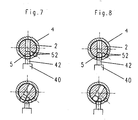
- the embodiment shown in Figures 7 and 8 differs from that of Figures 1-2 and 4-5 in that the coupling element is in the first coupling state in the interior of the rotor.
- the blocking of the output element 4 relative to the housing is effected by a blocking element, which corresponds to a propulsion means 42 - for example.
- This first coupling state is shown in FIG.
- the coupling element 5 is located completely within a circumferential line of the rotor 2. In the first coupling state shown in FIG.
- the coupling element is placed so that its equator is on the shearing line between the rotor and the output element 4 and thus couples the rotor and the output element (second coupling layer).
- the lifting spindle 42 is retracted in this second coupling state, so that the output element is rotatable.
- Drawn are still an inner and an outer support member 52, which cause the coupling element remains in the second coupling position even when the rotor is rotated and, for example. Gravity (in a rotation through 180 °) would move the coupling element against the rotor interior ,
- the mode of operation of this embodiment is the following: In the first coupling state (FIG. 8), the lifting spindle 42 blocks the output element 4 against the housing.
- the coupling element prevents rotation of the rotor, unless other means (key blocking element or the like) prevent rotation of the rotor, this is freely rotatable, but without effect (Fig. 8, bottom picture).
- a transition to the second coupling state is, for example, only possible if the system is in the aligned orientation according to FIG. 8, upper picture, which can be effected again by a key blocking element.
- the lifting spindle is electronically controlled retracted, thereby causing the coupling element is moved into the second coupling position, for example.
- the rotor By gravity, a magnetic force as in the preceding examples and / or acting on the outer of the Halteelmente 52 and of this passed over the inner support member 52 spring force.
- the rotor In the second coupling state, the rotor is rotatable and the driven element coupled with it: the bolt can be operated.
- the outer holding element 52 is located - for example, initially pressed by a spring force - within an outer circumferential line of the output element and, when the driven element is rotated away, by housing - or stator - held within this outer circumferential line. As a result, it causes, via the inner retaining element 52, that the coupling element 5 slips against the inside.
- the transition from the second to the first coupling state is possible only in the aligned in the upper image of Figure 7 oriented orientation.
- the lifting spindle presses the coupling element into the interior of the rotor, blocking the output element against the housing.
- the holding elements 52 are displaced outwards, wherein in this orientation for the outer holding element a en Maschinenende recess is present, where it is, for example. against the mentioned spring force is pressed.
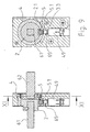
- FIGS. 9, 10 and 11 An example is drawn very schematically in FIGS. 9, 10 and 11. Elements which have already been described with reference to Figures 1, 2, 4 and 5, have the same reference numerals and will not be described again here; already described modes of action are also not explained again.
- the rotor 2 is directly connected to a door handle or an effect similar means or a door knob, for example.
- a shaft 61 of the door handle or doorknob is formed as a square and engages in a corresponding opening in the rotor.
- the output element is often mounted on an axle, which lies in the installed state over an axis of a lock cylinder and on the locking means. There are then appropriate (not shown) coupling means present which couple the output element with underlying locking means.
- the axis of a door knob often corresponds to the axis of the replaced by the doorknob locking cylinder.
- the locking device is drawn in the second coupling state: the coupling element 5 protrudes into a recess in the rotor and thereby couples rotor and driven element.
- the output member 4 may be directly connected to an inside door handle or effect-like means (only a square shaft 62 drawn). Case wise. the output element in the first coupling state coupled to the housing 3, which leads to a blocking of the inside door handle.
- a channel 3.3 is provided in the housing, which forms a link and in which the coupling element 5 located in the first coupling state can move together with the output element 4 between two stops without the rotor rotating (FIG. 10).
- the coupling element 5 in the first coupling state, may, for example, be such that it does not couple the output element to the housing, for example by being pulled back so far that it no longer protrudes into the opening of the output element.
- the coupling element 5 is not spherical but formed like a pin. It is not here as a whole magnetic but has on its underside an insert 5.1 made of ferromagnetic material, for example. Of permanently magnetic material. Between the lifting spindle 42 (or the permanent magnet 45) and the coupling element 5 is a here spherical intermediate element 65 made of magnetic material.
- the intermediate element 65 has the following functions: Due to its at least partially spherical surface and thus only .punberichten bearing surfaces prevents rotational movements are transmitted from the lifting spindle to the coupling element, whereby friction losses would occur.
- the drive means can be brought into the second coupling state even if the output element and coupling means are not in the starting position, for example. Due to a partial actuation of the inner door handle or effect-like means. This is shown in FIG. In a return movement of output element and coupling means in the starting position, for example. Due to the action of a spring cause the surfaces of intermediate element 65 and coupling element 5 that the Kupplungselment 5 is shifted upward and engages in the recess 2.1 of the rotor, ie directly into the second clutch position is shifted.
- the locking device according to the invention is particularly advantageous in the case of a direct operative connection between the door handle or the door knob and the rotor, since particularly large torques can be exerted by these means.
- the inventive decoupling of rotor 2 and driven element 4 in the first coupling state is therefore particularly advantageous here.
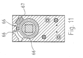
- FIG. 11 a section through the line (XI-XI) is drawn in FIG. 9.
- Recognizable is a spring 66 for returning the output element (and possibly the inner door handle or effect-like element) and a stop element 67, which is designed as a simple insert and allows a switch between a mode with rotation to the left and a mode of rotation to the right.
- a locking cylinder which may be mechanically functioning.
Landscapes
- Physics & Mathematics (AREA)
- Electromagnetism (AREA)
- Lock And Its Accessories (AREA)
Claims (18)
- Dispositif de verrouillage, comprenant :- un boîtier ; et- des moyens de verrouillage et d'accouplement qui présentent un élément d'accouplement (5, 5') et un moyen d'entraînement (23) relié au boîtier et commandé électroniquement, comportant des moyens d'avancement (42) pour déplacer l'élément d'accouplement (5, 5'), de sorte que les moyens de verrouillage et d'accouplement peuvent être amenés dans un premier et dans un second état d'accouplement ; et- un élément mené (4) qui est réalisé pour actionner des moyens à pêne,dans lequel :- l'élément d'accouplement (5, 5') est positionné dans le premier état d'accouplement de sorte qu'un rotor (2) n'est pas accouplé à l'élément mené (4) ;- l'élément d'accouplement (5, 5') est positionné dans le second état d'accouplement de sorte qu'il accouple l'élément mené (4) au rotor (2) ; et- l'élément d'accouplement (5, 5') peut être découplé des moyens d'avancement (42) de manière à pouvoir être déplacé à l'écart des moyens d'avancement (42) par un mouvement de rotation du rotor (2) dans le second état d'accouplement.
- Dispositif de verrouillage selon l'une des revendications précédentes, caractérisé en ce que l'élément d'accouplement (5, 5') possède une surface au moins partiellement sphérique et est réalisé par exemple comme bille.
- Dispositif de verrouillage selon l'une des revendications précédentes, caractérisé en ce que l'élément d'accouplement (5, 5') n'est accouplé fermement, ni au boîtier, ni au rotor (2).
- Dispositif de verrouillage selon la revendication 3, caractérisé en ce que l'élément d'accouplement est tourné simultanément dans sa seconde position d'accouplement en cas d'un mouvement de rotation du rotor (2) dans une ouverture, laquelle est formée par des évidements (2.1, 4.1) dans le rotor (2) et dans l'élément mené (4).
- Dispositif de verrouillage selon l'une des revendications précédentes, caractérisé en ce que l'élément d'accouplement peut être déplacé par guidage quasiment forcé par le moyen d'entraînement, par exemple par couplage à un aimant permanent (45) relié au moyen d'avancement (42).
- Dispositif de verrouillage selon l'une des revendications précédentes, dans lequel le moyen d'entraînement présente un entraînement rotatif et une broche de levée (42).
- Dispositif de verrouillage selon l'une des revendications précédentes, caractérisé en ce que le moyen d'entraînement est muni de moyens faisant ressort (46) qui sont réalisés et agencés de sorte que l'élément d'accouplement (5, 5') se trouvant entre la première position d'accouplement et la seconde position d'accouplement peut être déplacé par action mécanique à l'encontre d'une force de ressort en direction de la première position d'accouplement.
- Dispositif de verrouillage selon l'une des revendications précédentes, caractérisé en ce que l'élément mené (4) est bloqué par rapport au boîtier dans le premier état d'accouplement et en ce que l'élément mené (4) n'est pas accouplé au boîtier dans le second état d'accouplement.
- Dispositif de verrouillage selon la revendication 8, caractérisé en ce que l'élément d'accouplement (5, 5') bloque l'élément mené (4) par rapport au boîtier dans la première position d'accouplement.
- Dispositif de verrouillage selon la revendication 8, caractérisé en ce qu'un élément de blocage (42) bloque l'élément mené (4) par rapport au boîtier dans la première position d'accouplement, l'élément de blocage et l'élément d'accouplement (5, 5') étant agencés de sorte qu'un mouvement de l'élément de blocage provoque un mouvement de l'élément d'accouplement (5, 5') au niveau de la transition entre le premier état et le second état.
- Dispositif de verrouillage selon l'une des revendications précédentes, pour l'utilisation dans un cylindre de fermeture, caractérisé en ce qu'il est exempt d'arrêts de gâchette pouvant être actionnés de manière purement mécanique.
- Dispositif de verrouillage selon l'une des revendications 1 à 10, pour l'utilisation dans un cylindre de fermeture, caractérisé par des arrêts de gâchette mécaniques pour l'engagement dans des renfoncements d'une clé.
- Dispositif de verrouillage selon l'une des revendications 1 à 11, pour l'utilisation dans un cylindre de fermeture, caractérisé par un élément de blocage de clé (24) qui peut être déplacé depuis une première position vers une seconde position par l'introduction d'une clé (30) dans une ouverture de clé (2.2), ledit élément étant réalisé et agencé de manière à permettre une extraction de la clé dans la seconde position seulement pour certaines orientations prescrites du rotor (2).
- Dispositif de verrouillage selon la revendication 13, caractérisé en ce que l'élément de blocage de clé est réalisé et agencé de manière à bloquer, sans sa première position, le rotor (2) contre des rotations.
- Dispositif de verrouillage selon l'une des revendications 1 à 7, pour l'utilisation avec une poignée de porte ou un moyen à action similaire, caractérisé en ce que :- le rotor (2) peut être couplé à une poignée de porte extérieure ou à un moyen à action similaire ;- l'élément mené (4) peut être couplé à une poignée de porte intérieure ou à un moyen à action similaire ; et- l'élément d'accouplement est agencé dans le premier état d'accouplement de sorte que l'élément mené (4) n'est pas loqué.
- Dispositif de verrouillage selon la revendication 15, caractérisé en ce qu'un conduit (3.3) dans lequel l'élément d'accouplement (5) peut être déplacé par une rotation de l'élément mené lorsqu'il se trouve dans le premier état d'accouplement, est réalisé dans une zone du boîtier (3), laquelle guide l'élément mené (4).
- Dispositif de verrouillage selon l'une des revendications précédentes, caractérisé par un élément intermédiaire (65) qui est agencé entre les moyens d'avancement et l'élément d'accouplement, et qui présente une surface au moins partiellement sphérique.
- Dispositif de verrouillage selon l'une des revendications précédentes, caractérisé en ce que l'élément d'accouplement présente un insert (5.1) constitué d'un matériau ferromagnétique, de préférence magnétisé en permanence.
Applications Claiming Priority (3)
| Application Number | Priority Date | Filing Date | Title |
|---|---|---|---|
| CH22042002 | 2002-12-23 | ||
| CH220402 | 2002-12-23 | ||
| PCT/CH2003/000831 WO2004057137A1 (fr) | 2002-12-23 | 2003-12-18 | Dispositif de verrouillage |
Publications (2)
| Publication Number | Publication Date |
|---|---|
| EP1576246A1 EP1576246A1 (fr) | 2005-09-21 |
| EP1576246B1 true EP1576246B1 (fr) | 2006-08-30 |
Family
ID=32661021
Family Applications (1)
| Application Number | Title | Priority Date | Filing Date |
|---|---|---|---|
| EP03813512A Expired - Lifetime EP1576246B1 (fr) | 2002-12-23 | 2003-12-18 | Dispositif de verrouillage |
Country Status (9)
| Country | Link |
|---|---|
| US (1) | US20060156771A1 (fr) |
| EP (1) | EP1576246B1 (fr) |
| JP (1) | JP4731912B2 (fr) |
| AT (1) | ATE338181T1 (fr) |
| AU (1) | AU2003303213A1 (fr) |
| CA (1) | CA2511488A1 (fr) |
| DE (1) | DE50304899D1 (fr) |
| ES (1) | ES2274321T3 (fr) |
| WO (1) | WO2004057137A1 (fr) |
Cited By (3)
| Publication number | Priority date | Publication date | Assignee | Title |
|---|---|---|---|---|
| EP2940232A1 (fr) | 2014-04-30 | 2015-11-04 | ABUS August Bremicker Söhne KG | Dispositif d'accouplement |
| EP3741934A1 (fr) | 2019-05-22 | 2020-11-25 | Astra Gesellschaft Für Asset Management MbH&Co. Kg | Cylindre de fermeture |
| EP4575150A1 (fr) | 2023-12-22 | 2025-06-25 | Astra Gesellschaft Für Asset Management MbH&Co. Kg | Unité de fermeture électrique |
Families Citing this family (34)
| Publication number | Priority date | Publication date | Assignee | Title |
|---|---|---|---|---|
| ATE542008T1 (de) * | 2004-03-11 | 2012-02-15 | Keso Ag | Elektromechanischer schliesszylinder |
| US20070017265A1 (en) * | 2005-07-22 | 2007-01-25 | Assa Ab | Lock device |
| DE102005059384B4 (de) * | 2005-12-09 | 2011-07-07 | Burg-Wächter KG, 58540 | Schloss |
| DE102006010435B4 (de) * | 2005-12-09 | 2013-01-17 | Burg-Wächter Kg | Schloss |
| EP1966455B1 (fr) | 2005-12-27 | 2018-03-14 | ASSA ABLOY (Schweiz) AG | Cylindre de fermeture rotatif electromecanique |
| CH699726B1 (de) * | 2006-11-16 | 2010-04-30 | Kaba Ag | Schliessvorrichtung. |
| EP2428628B1 (fr) | 2007-03-05 | 2018-11-28 | dormakaba Schweiz AG | Système pour le contrôle d'accès et dispositif de fermeture |
| EP2017412B1 (fr) * | 2007-07-18 | 2015-10-14 | iLOQ Oy | Serrure électromécanique |
| CN101591994B (zh) * | 2008-05-28 | 2012-06-27 | 罗士夫 | 微功耗无源电子锁头 |
| IL193931A (en) * | 2008-09-07 | 2012-01-31 | Mul T Lock Technologies Ltd | Movable key combination element and lock assembly |
| CH700665B1 (de) | 2009-03-18 | 2013-05-31 | Kaba Ag | Verriegelungsvorrichtung. |
| CH701503A2 (de) | 2009-07-29 | 2011-01-31 | Kaba Ag | Elektronische schliesseinrichtung. |
| CH701790B1 (de) | 2009-08-31 | 2026-04-15 | Kaba Ag | Schliesseinrichtung. |
| CN102191878A (zh) * | 2011-05-19 | 2011-09-21 | 陈润明 | 智能门锁面板装置 |
| WO2012171899A1 (fr) * | 2011-06-16 | 2012-12-20 | Futurama Innovation Ab | Agencement de transmission de couple |
| US8978428B2 (en) * | 2011-09-08 | 2015-03-17 | Medeco Security Locks, Inc. | Apparatus for automatically returning a lock to a desired orientation |
| AT513287A1 (de) * | 2012-07-12 | 2014-03-15 | Evva Sicherheitstechnologie | Schlüssel und Zutrittskontrollvorrichtung mit Schlüssel |
| KR101237738B1 (ko) * | 2012-09-27 | 2013-02-26 | 김범수 | 전자식 잠금장치용 키실린더 |
| ITTO20121114A1 (it) * | 2012-12-20 | 2014-06-21 | Rielda Serrature Srl | Serratura elettromeccanica anti-shock |
| WO2014096442A2 (fr) * | 2012-12-23 | 2014-06-26 | Certaflex Bv | Serrure à cylindre et combinaison d'une telle serrure et d'une clé |
| JP6000169B2 (ja) * | 2013-03-14 | 2016-09-28 | 株式会社ホンダロック | シリンダ錠 |
| DE102013010566A1 (de) * | 2013-06-14 | 2014-12-18 | Assa Abloy Sicherheitstechnik Gmbh | Bewegungssperre für ein Sperrelement oder einen Aktuator in einem Schließsystem |
| CN103334644B (zh) | 2013-07-25 | 2015-04-15 | 四川润智兴科技有限公司 | 高安全性离合电子锁头 |
| US9133647B2 (en) | 2013-10-11 | 2015-09-15 | Nexkey, Inc. | NFC or BLE based contactless lock with charge monitoring of its energy storage |
| EP2998478B1 (fr) * | 2014-09-22 | 2019-04-17 | BKS GmbH | Serrure à mortaiser pour une porte et ensemble de serrure pour une porte |
| DE102015105412B3 (de) * | 2015-04-09 | 2016-07-07 | Assa Abloy Sicherheitstechnik Gmbh | Schließzylinder |
| EP3118977B1 (fr) * | 2015-07-13 | 2019-06-26 | iLOQ Oy | Serrure électromécanique utilisant des forces de champ magnétique |
| US10794089B2 (en) * | 2016-11-09 | 2020-10-06 | Quanzhou Guoguang Software Development Co., Ltd. | Security lock |
| CN106760996B (zh) * | 2016-12-19 | 2022-03-29 | 成都嘿芝麻科技有限公司 | 自动锁定非空转电子锁 |
| UA118611C2 (uk) | 2017-04-28 | 2019-02-11 | Леонід Полікарпович Пашкевич | Замок-блокіратор з матричною системою кодування |
| ES2963085T3 (es) * | 2018-03-02 | 2024-03-25 | Assa Abloy Ab | Dispositivo de bloqueo para un sistema de bloqueo electrónico, sistema de bloqueo electrónico y método |
| EP3927920A4 (fr) * | 2019-04-05 | 2022-12-21 | Dormakaba USA Inc. | Verrou électronique |
| SE543627C2 (en) * | 2019-10-03 | 2021-04-27 | Swedlock Ab | Electromechanical lock assembly with annular element and blocking arrangement comprising a retaining device |
| US12509916B2 (en) * | 2022-04-29 | 2025-12-30 | Iloq Oy | Electromechanical lock cylinder |
Family Cites Families (20)
| Publication number | Priority date | Publication date | Assignee | Title |
|---|---|---|---|---|
| JPS6147361U (ja) * | 1984-08-31 | 1986-03-29 | 株式会社東海理化電機製作所 | シリンダ錠 |
| GB2182089B (en) * | 1985-10-25 | 1989-12-13 | Lowe & Fletcher Ltd | Lock and key and method of operating lock |
| EP0312123A1 (fr) * | 1985-10-25 | 1989-04-19 | Lowe & Fletcher Limited | Dispositif de sécurité, en particulier serrure à commande électrique |
| CH671800A5 (fr) * | 1987-02-09 | 1989-09-29 | Berchtold Ag | |
| US4856310A (en) * | 1987-04-29 | 1989-08-15 | Raoul Parienti | Electronic lock |
| DE8914508U1 (de) * | 1989-02-02 | 1990-06-13 | DOM-Sicherheitstechnik GmbH & Co KG, 5040 Brühl | Schließzylinder, insbesondere für Einsteckschlösser |
| FR2655367B1 (fr) * | 1989-12-05 | 1992-04-03 | Vachette Sa | Serrure a barillet double a condamnation mecanique et electrique. |
| US4995248A (en) * | 1990-04-16 | 1991-02-26 | Liu Yin Chic | Control mechanism of electronic lock having double bolts |
| WO1995012047A1 (fr) * | 1993-10-29 | 1995-05-04 | Sargent & Greenleaf, Inc. | Serrure a combinaison electronique |
| US5475996A (en) * | 1994-08-29 | 1995-12-19 | Chen; Tsun-Hsing | Electromagnetic door lock |
| US5640863A (en) * | 1995-09-06 | 1997-06-24 | Harrow Products, Inc. | Clutch mechanism for door lock system |
| AU729639B2 (en) * | 1996-12-24 | 2001-02-08 | Kaba Schliesssysteme Ag | Locking device |
| US6442986B1 (en) * | 1998-04-07 | 2002-09-03 | Best Lock Corporation | Electronic token and lock core |
| US6058751A (en) * | 1998-09-08 | 2000-05-09 | Strattec Security Corporation | Free-wheeling lock |
| AU6145300A (en) * | 1999-09-21 | 2001-04-24 | Berchtold Ag | Blocking device for a cylinder lock |
| US6718806B2 (en) * | 2000-01-25 | 2004-04-13 | Videx, Inc. | Electronic locking system with emergency exit feature |
| US6474122B2 (en) * | 2000-01-25 | 2002-11-05 | Videx, Inc. | Electronic locking system |
| US6615625B2 (en) * | 2000-01-25 | 2003-09-09 | Videx, Inc. | Electronic locking system |
| ES2191522B1 (es) * | 2000-12-11 | 2004-11-01 | Talleres De Escoriaza, S.A. | Dispositivo de embrague para cerrajeria. |
| GB2390394B (en) * | 2002-07-03 | 2004-05-26 | Shyang Feng Electric & Machine | Improved electronic lock |
-
2003
- 2003-12-18 EP EP03813512A patent/EP1576246B1/fr not_active Expired - Lifetime
- 2003-12-18 DE DE50304899T patent/DE50304899D1/de not_active Expired - Lifetime
- 2003-12-18 JP JP2004560982A patent/JP4731912B2/ja not_active Expired - Lifetime
- 2003-12-18 WO PCT/CH2003/000831 patent/WO2004057137A1/fr not_active Ceased
- 2003-12-18 CA CA002511488A patent/CA2511488A1/fr not_active Abandoned
- 2003-12-18 ES ES03813512T patent/ES2274321T3/es not_active Expired - Lifetime
- 2003-12-18 US US10/540,504 patent/US20060156771A1/en not_active Abandoned
- 2003-12-18 AT AT03813512T patent/ATE338181T1/de active
- 2003-12-18 AU AU2003303213A patent/AU2003303213A1/en not_active Abandoned
Cited By (8)
| Publication number | Priority date | Publication date | Assignee | Title |
|---|---|---|---|---|
| EP2940232A1 (fr) | 2014-04-30 | 2015-11-04 | ABUS August Bremicker Söhne KG | Dispositif d'accouplement |
| DE102014106110A1 (de) | 2014-04-30 | 2015-11-05 | ABUS August Bremicker Söhne KG | Kupplungsvorrichtung |
| DE102014106110B4 (de) | 2014-04-30 | 2023-06-07 | ABUS August Bremicker Söhne Kommanditgesellschaft | Kupplungsvorrichtung |
| EP3741934A1 (fr) | 2019-05-22 | 2020-11-25 | Astra Gesellschaft Für Asset Management MbH&Co. Kg | Cylindre de fermeture |
| DE102019113666A1 (de) * | 2019-05-22 | 2020-11-26 | ASTRA Gesellschaft für Asset Management mbH & Co. KG | Schließzylinder |
| DE102019113666B4 (de) | 2019-05-22 | 2022-09-29 | ASTRA Gesellschaft für Asset Management mbH & Co. KG | Elektrischer Schließzylinder für ein Schloss |
| EP4575150A1 (fr) | 2023-12-22 | 2025-06-25 | Astra Gesellschaft Für Asset Management MbH&Co. Kg | Unité de fermeture électrique |
| DE102023136459A1 (de) * | 2023-12-22 | 2025-06-26 | ASTRA Gesellschaft für Asset Management mbH & Co. KG | Elektrische Schließeinheit |
Also Published As
| Publication number | Publication date |
|---|---|
| WO2004057137A8 (fr) | 2005-08-11 |
| JP2006511738A (ja) | 2006-04-06 |
| WO2004057137A1 (fr) | 2004-07-08 |
| US20060156771A1 (en) | 2006-07-20 |
| ATE338181T1 (de) | 2006-09-15 |
| DE50304899D1 (de) | 2006-10-12 |
| CA2511488A1 (fr) | 2004-07-08 |
| JP4731912B2 (ja) | 2011-07-27 |
| ES2274321T3 (es) | 2007-05-16 |
| EP1576246A1 (fr) | 2005-09-21 |
| AU2003303213A1 (en) | 2004-07-14 |
Similar Documents
| Publication | Publication Date | Title |
|---|---|---|
| EP1576246B1 (fr) | Dispositif de verrouillage | |
| EP1214491B1 (fr) | Unite de verrouillage pour une serrure a barillet | |
| EP2201535B1 (fr) | Dispositif de verrouillage | |
| DE69903872T2 (de) | Elektromechanisches Zylinderschloss | |
| DE3632904C2 (fr) | ||
| EP1443162B1 (fr) | Serrure cylindrique | |
| EP1155427B1 (fr) | Dispositif pour la reception et le maintien d'un dispositif d'identification, tel qu'une cle electronique, en particulier pour un demarreur a allumage | |
| EP0526904A1 (fr) | Serrure à cylindre, notamment pour serrure encastrée | |
| DE10320873A1 (de) | Bewegungsübertragungsvorrichtung und -verfahren | |
| DE19848286B4 (de) | Kopplungsbaugruppe für ein Elektromechanisches Schließsystem | |
| DE19930054C5 (de) | Elektromechanisches Schließsystem | |
| EP0668422A1 (fr) | Mécanisme de blocage pour serrure | |
| DE102022132983B3 (de) | Türöffner | |
| DE102010063477B4 (de) | Fernentriegelbare Torverriegelung | |
| DE3641562C2 (de) | Türschloss | |
| EP0805905B1 (fr) | Mécanisme de fermeture de porte | |
| DE102007011554B4 (de) | Koppeleinheit für elektronische Schließ-Systeme | |
| DE112007002578B4 (de) | Schließzylinder | |
| DE102004063126B3 (de) | Elektromechanisches Schließsystem | |
| EP1662076B1 (fr) | Dispositif d'accouplement pour un dispositif de verrouillage | |
| DE102006024063B4 (de) | Schloss mit einem durch einen elektrischmechanisch betätigten Sperrstift verriegelbaren Schließzylinder | |
| EP1931843B1 (fr) | Dispositif de verrouillage | |
| EP3680425A1 (fr) | Agencement de commande de porte ainsi que porte | |
| EP1164238A1 (fr) | Serrure cylindrique | |
| EP2505749B1 (fr) | Cylindre de fermeture pour un verrou |
Legal Events
| Date | Code | Title | Description |
|---|---|---|---|
| PUAI | Public reference made under article 153(3) epc to a published international application that has entered the european phase |
Free format text: ORIGINAL CODE: 0009012 |
|
| 17P | Request for examination filed |
Effective date: 20050622 |
|
| AK | Designated contracting states |
Kind code of ref document: A1 Designated state(s): AT BE BG CH CY CZ DE DK EE ES FI FR GB GR HU IE IT LI LU MC NL PT RO SE SI SK TR |
|
| AX | Request for extension of the european patent |
Extension state: AL LT LV MK |
|
| GRAP | Despatch of communication of intention to grant a patent |
Free format text: ORIGINAL CODE: EPIDOSNIGR1 |
|
| DAX | Request for extension of the european patent (deleted) | ||
| GRAS | Grant fee paid |
Free format text: ORIGINAL CODE: EPIDOSNIGR3 |
|
| GRAA | (expected) grant |
Free format text: ORIGINAL CODE: 0009210 |
|
| AK | Designated contracting states |
Kind code of ref document: B1 Designated state(s): AT BE BG CH CY CZ DE DK EE ES FI FR GB GR HU IE IT LI LU MC NL PT RO SE SI SK TR |
|
| PG25 | Lapsed in a contracting state [announced via postgrant information from national office to epo] |
Ref country code: CZ Free format text: LAPSE BECAUSE OF FAILURE TO SUBMIT A TRANSLATION OF THE DESCRIPTION OR TO PAY THE FEE WITHIN THE PRESCRIBED TIME-LIMIT Effective date: 20060830 Ref country code: SK Free format text: LAPSE BECAUSE OF FAILURE TO SUBMIT A TRANSLATION OF THE DESCRIPTION OR TO PAY THE FEE WITHIN THE PRESCRIBED TIME-LIMIT Effective date: 20060830 Ref country code: SI Free format text: LAPSE BECAUSE OF FAILURE TO SUBMIT A TRANSLATION OF THE DESCRIPTION OR TO PAY THE FEE WITHIN THE PRESCRIBED TIME-LIMIT Effective date: 20060830 Ref country code: FI Free format text: LAPSE BECAUSE OF FAILURE TO SUBMIT A TRANSLATION OF THE DESCRIPTION OR TO PAY THE FEE WITHIN THE PRESCRIBED TIME-LIMIT Effective date: 20060830 Ref country code: RO Free format text: LAPSE BECAUSE OF FAILURE TO SUBMIT A TRANSLATION OF THE DESCRIPTION OR TO PAY THE FEE WITHIN THE PRESCRIBED TIME-LIMIT Effective date: 20060830 Ref country code: IE Free format text: LAPSE BECAUSE OF FAILURE TO SUBMIT A TRANSLATION OF THE DESCRIPTION OR TO PAY THE FEE WITHIN THE PRESCRIBED TIME-LIMIT Effective date: 20060830 |
|
| REG | Reference to a national code |
Ref country code: GB Ref legal event code: FG4D Free format text: NOT ENGLISH |
|
| REG | Reference to a national code |
Ref country code: CH Ref legal event code: EP |
|
| REG | Reference to a national code |
Ref country code: IE Ref legal event code: FG4D Free format text: LANGUAGE OF EP DOCUMENT: GERMAN |
|
| REF | Corresponds to: |
Ref document number: 50304899 Country of ref document: DE Date of ref document: 20061012 Kind code of ref document: P |
|
| GBT | Gb: translation of ep patent filed (gb section 77(6)(a)/1977) |
Effective date: 20061101 |
|
| PG25 | Lapsed in a contracting state [announced via postgrant information from national office to epo] |
Ref country code: BG Free format text: LAPSE BECAUSE OF FAILURE TO SUBMIT A TRANSLATION OF THE DESCRIPTION OR TO PAY THE FEE WITHIN THE PRESCRIBED TIME-LIMIT Effective date: 20061130 Ref country code: DK Free format text: LAPSE BECAUSE OF FAILURE TO SUBMIT A TRANSLATION OF THE DESCRIPTION OR TO PAY THE FEE WITHIN THE PRESCRIBED TIME-LIMIT Effective date: 20061130 |
|
| REG | Reference to a national code |
Ref country code: SE Ref legal event code: TRGR |
|
| REG | Reference to a national code |
Ref country code: CH Ref legal event code: NV Representative=s name: FREI PATENTANWALTSBUERO AG |
|
| PG25 | Lapsed in a contracting state [announced via postgrant information from national office to epo] |
Ref country code: BE Free format text: LAPSE BECAUSE OF NON-PAYMENT OF DUE FEES Effective date: 20061231 Ref country code: MC Free format text: LAPSE BECAUSE OF NON-PAYMENT OF DUE FEES Effective date: 20061231 |
|
| PG25 | Lapsed in a contracting state [announced via postgrant information from national office to epo] |
Ref country code: PT Free format text: LAPSE BECAUSE OF FAILURE TO SUBMIT A TRANSLATION OF THE DESCRIPTION OR TO PAY THE FEE WITHIN THE PRESCRIBED TIME-LIMIT Effective date: 20070206 |
|
| ET | Fr: translation filed | ||
| REG | Reference to a national code |
Ref country code: IE Ref legal event code: FD4D |
|
| REG | Reference to a national code |
Ref country code: ES Ref legal event code: FG2A Ref document number: 2274321 Country of ref document: ES Kind code of ref document: T3 |
|
| PLBE | No opposition filed within time limit |
Free format text: ORIGINAL CODE: 0009261 |
|
| STAA | Information on the status of an ep patent application or granted ep patent |
Free format text: STATUS: NO OPPOSITION FILED WITHIN TIME LIMIT |
|
| 26N | No opposition filed |
Effective date: 20070531 |
|
| BERE | Be: lapsed |
Owner name: KABA A.G. Effective date: 20061231 |
|
| PG25 | Lapsed in a contracting state [announced via postgrant information from national office to epo] |
Ref country code: GR Free format text: LAPSE BECAUSE OF FAILURE TO SUBMIT A TRANSLATION OF THE DESCRIPTION OR TO PAY THE FEE WITHIN THE PRESCRIBED TIME-LIMIT Effective date: 20061201 |
|
| PG25 | Lapsed in a contracting state [announced via postgrant information from national office to epo] |
Ref country code: EE Free format text: LAPSE BECAUSE OF FAILURE TO SUBMIT A TRANSLATION OF THE DESCRIPTION OR TO PAY THE FEE WITHIN THE PRESCRIBED TIME-LIMIT Effective date: 20060830 |
|
| PG25 | Lapsed in a contracting state [announced via postgrant information from national office to epo] |
Ref country code: TR Free format text: LAPSE BECAUSE OF FAILURE TO SUBMIT A TRANSLATION OF THE DESCRIPTION OR TO PAY THE FEE WITHIN THE PRESCRIBED TIME-LIMIT Effective date: 20060830 Ref country code: HU Free format text: LAPSE BECAUSE OF FAILURE TO SUBMIT A TRANSLATION OF THE DESCRIPTION OR TO PAY THE FEE WITHIN THE PRESCRIBED TIME-LIMIT Effective date: 20070301 Ref country code: LU Free format text: LAPSE BECAUSE OF NON-PAYMENT OF DUE FEES Effective date: 20061218 |
|
| PG25 | Lapsed in a contracting state [announced via postgrant information from national office to epo] |
Ref country code: CY Free format text: LAPSE BECAUSE OF FAILURE TO SUBMIT A TRANSLATION OF THE DESCRIPTION OR TO PAY THE FEE WITHIN THE PRESCRIBED TIME-LIMIT Effective date: 20060830 |
|
| PGFP | Annual fee paid to national office [announced via postgrant information from national office to epo] |
Ref country code: ES Payment date: 20091222 Year of fee payment: 7 Ref country code: SE Payment date: 20091214 Year of fee payment: 7 |
|
| PGFP | Annual fee paid to national office [announced via postgrant information from national office to epo] |
Ref country code: NL Payment date: 20091222 Year of fee payment: 7 |
|
| PGFP | Annual fee paid to national office [announced via postgrant information from national office to epo] |
Ref country code: IT Payment date: 20091223 Year of fee payment: 7 |
|
| PGFP | Annual fee paid to national office [announced via postgrant information from national office to epo] |
Ref country code: FR Payment date: 20110104 Year of fee payment: 8 |
|
| PGFP | Annual fee paid to national office [announced via postgrant information from national office to epo] |
Ref country code: GB Payment date: 20101221 Year of fee payment: 8 |
|
| REG | Reference to a national code |
Ref country code: NL Ref legal event code: V1 Effective date: 20110701 |
|
| REG | Reference to a national code |
Ref country code: SE Ref legal event code: EUG |
|
| PG25 | Lapsed in a contracting state [announced via postgrant information from national office to epo] |
Ref country code: SE Free format text: LAPSE BECAUSE OF NON-PAYMENT OF DUE FEES Effective date: 20101219 |
|
| PG25 | Lapsed in a contracting state [announced via postgrant information from national office to epo] |
Ref country code: IT Free format text: LAPSE BECAUSE OF NON-PAYMENT OF DUE FEES Effective date: 20101218 Ref country code: NL Free format text: LAPSE BECAUSE OF NON-PAYMENT OF DUE FEES Effective date: 20110701 |
|
| REG | Reference to a national code |
Ref country code: ES Ref legal event code: FD2A Effective date: 20120220 |
|
| PG25 | Lapsed in a contracting state [announced via postgrant information from national office to epo] |
Ref country code: ES Free format text: LAPSE BECAUSE OF NON-PAYMENT OF DUE FEES Effective date: 20101219 |
|
| GBPC | Gb: european patent ceased through non-payment of renewal fee |
Effective date: 20111218 |
|
| REG | Reference to a national code |
Ref country code: FR Ref legal event code: ST Effective date: 20120831 |
|
| PG25 | Lapsed in a contracting state [announced via postgrant information from national office to epo] |
Ref country code: GB Free format text: LAPSE BECAUSE OF NON-PAYMENT OF DUE FEES Effective date: 20111218 |
|
| PG25 | Lapsed in a contracting state [announced via postgrant information from national office to epo] |
Ref country code: FR Free format text: LAPSE BECAUSE OF NON-PAYMENT OF DUE FEES Effective date: 20120102 |
|
| REG | Reference to a national code |
Ref country code: CH Ref legal event code: PCAR Free format text: NEW ADDRESS: POSTFACH, 8032 ZUERICH (CH) |
|
| PGFP | Annual fee paid to national office [announced via postgrant information from national office to epo] |
Ref country code: DE Payment date: 20221213 Year of fee payment: 20 Ref country code: AT Payment date: 20221222 Year of fee payment: 20 |
|
| PGFP | Annual fee paid to national office [announced via postgrant information from national office to epo] |
Ref country code: CH Payment date: 20230103 Year of fee payment: 20 |
|
| REG | Reference to a national code |
Ref country code: DE Ref legal event code: R071 Ref document number: 50304899 Country of ref document: DE |
|
| REG | Reference to a national code |
Ref country code: CH Ref legal event code: PL |
|
| REG | Reference to a national code |
Ref country code: AT Ref legal event code: MK07 Ref document number: 338181 Country of ref document: AT Kind code of ref document: T Effective date: 20231218 |