EP1576246B1 - Locking device - Google Patents
Locking device Download PDFInfo
- Publication number
- EP1576246B1 EP1576246B1 EP03813512A EP03813512A EP1576246B1 EP 1576246 B1 EP1576246 B1 EP 1576246B1 EP 03813512 A EP03813512 A EP 03813512A EP 03813512 A EP03813512 A EP 03813512A EP 1576246 B1 EP1576246 B1 EP 1576246B1
- Authority
- EP
- European Patent Office
- Prior art keywords
- coupling
- locking device
- rotor
- drive
- coupling element
- Prior art date
- Legal status (The legal status is an assumption and is not a legal conclusion. Google has not performed a legal analysis and makes no representation as to the accuracy of the status listed.)
- Expired - Lifetime
Links
- 230000008878 coupling Effects 0.000 claims abstract description 222
- 238000010168 coupling process Methods 0.000 claims abstract description 222
- 238000005859 coupling reaction Methods 0.000 claims abstract description 222
- 230000033001 locomotion Effects 0.000 claims abstract description 14
- 230000000903 blocking effect Effects 0.000 claims description 25
- 230000000694 effects Effects 0.000 claims description 11
- 230000009471 action Effects 0.000 claims description 7
- 230000007704 transition Effects 0.000 claims description 5
- 239000000463 material Substances 0.000 claims description 3
- 230000005294 ferromagnetic effect Effects 0.000 claims 1
- 230000005291 magnetic effect Effects 0.000 description 8
- 238000004891 communication Methods 0.000 description 6
- 230000035939 shock Effects 0.000 description 5
- 238000013459 approach Methods 0.000 description 4
- 239000003302 ferromagnetic material Substances 0.000 description 4
- 230000007246 mechanism Effects 0.000 description 4
- 230000005540 biological transmission Effects 0.000 description 3
- 239000002655 kraft paper Substances 0.000 description 3
- 238000010008 shearing Methods 0.000 description 3
- XEEYBQQBJWHFJM-UHFFFAOYSA-N Iron Chemical compound [Fe] XEEYBQQBJWHFJM-UHFFFAOYSA-N 0.000 description 2
- PXHVJJICTQNCMI-UHFFFAOYSA-N Nickel Chemical compound [Ni] PXHVJJICTQNCMI-UHFFFAOYSA-N 0.000 description 2
- 238000013475 authorization Methods 0.000 description 2
- 230000008901 benefit Effects 0.000 description 2
- 239000007822 coupling agent Substances 0.000 description 2
- 238000010586 diagram Methods 0.000 description 2
- 230000005484 gravity Effects 0.000 description 2
- 239000000696 magnetic material Substances 0.000 description 2
- 230000003213 activating effect Effects 0.000 description 1
- 238000004026 adhesive bonding Methods 0.000 description 1
- 230000001070 adhesive effect Effects 0.000 description 1
- 230000004888 barrier function Effects 0.000 description 1
- 230000008094 contradictory effect Effects 0.000 description 1
- 238000013461 design Methods 0.000 description 1
- 230000005674 electromagnetic induction Effects 0.000 description 1
- 230000005670 electromagnetic radiation Effects 0.000 description 1
- 230000005284 excitation Effects 0.000 description 1
- 230000005333 ferromagnetic domain Effects 0.000 description 1
- 238000009434 installation Methods 0.000 description 1
- 229910052742 iron Inorganic materials 0.000 description 1
- 238000000034 method Methods 0.000 description 1
- 230000007935 neutral effect Effects 0.000 description 1
- 229910052759 nickel Inorganic materials 0.000 description 1
- 230000003716 rejuvenation Effects 0.000 description 1
- 230000001360 synchronised effect Effects 0.000 description 1
- 238000012360 testing method Methods 0.000 description 1
Images


Classifications
-
- E—FIXED CONSTRUCTIONS
- E05—LOCKS; KEYS; WINDOW OR DOOR FITTINGS; SAFES
- E05B—LOCKS; ACCESSORIES THEREFOR; HANDCUFFS
- E05B47/00—Operating or controlling locks or other fastening devices by electric or magnetic means
- E05B47/06—Controlling mechanically-operated bolts by electro-magnetically-operated detents
- E05B47/0611—Cylinder locks with electromagnetic control
- E05B47/0638—Cylinder locks with electromagnetic control by disconnecting the rotor
- E05B47/0646—Cylinder locks with electromagnetic control by disconnecting the rotor radially
- E05B47/0649—Cylinder locks with electromagnetic control by disconnecting the rotor radially with a rectilinearly moveable coupling element
-
- E—FIXED CONSTRUCTIONS
- E05—LOCKS; KEYS; WINDOW OR DOOR FITTINGS; SAFES
- E05B—LOCKS; ACCESSORIES THEREFOR; HANDCUFFS
- E05B17/00—Accessories in connection with locks
- E05B17/04—Devices for coupling the turning cylinder of a single or a double cylinder lock with the bolt operating member
-
- E—FIXED CONSTRUCTIONS
- E05—LOCKS; KEYS; WINDOW OR DOOR FITTINGS; SAFES
- E05B—LOCKS; ACCESSORIES THEREFOR; HANDCUFFS
- E05B47/00—Operating or controlling locks or other fastening devices by electric or magnetic means
- E05B47/0001—Operating or controlling locks or other fastening devices by electric or magnetic means with electric actuators; Constructional features thereof
- E05B2047/0014—Constructional features of actuators or power transmissions therefor
- E05B2047/0018—Details of actuator transmissions
- E05B2047/0023—Nuts or nut-like elements moving along a driven threaded axle
-
- E—FIXED CONSTRUCTIONS
- E05—LOCKS; KEYS; WINDOW OR DOOR FITTINGS; SAFES
- E05B—LOCKS; ACCESSORIES THEREFOR; HANDCUFFS
- E05B47/00—Operating or controlling locks or other fastening devices by electric or magnetic means
- E05B47/0001—Operating or controlling locks or other fastening devices by electric or magnetic means with electric actuators; Constructional features thereof
- E05B2047/0014—Constructional features of actuators or power transmissions therefor
- E05B2047/0018—Details of actuator transmissions
- E05B2047/0026—Clutches, couplings or braking arrangements
-
- E—FIXED CONSTRUCTIONS
- E05—LOCKS; KEYS; WINDOW OR DOOR FITTINGS; SAFES
- E05B—LOCKS; ACCESSORIES THEREFOR; HANDCUFFS
- E05B47/00—Operating or controlling locks or other fastening devices by electric or magnetic means
- E05B47/0001—Operating or controlling locks or other fastening devices by electric or magnetic means with electric actuators; Constructional features thereof
- E05B47/0012—Operating or controlling locks or other fastening devices by electric or magnetic means with electric actuators; Constructional features thereof with rotary electromotors
-
- Y—GENERAL TAGGING OF NEW TECHNOLOGICAL DEVELOPMENTS; GENERAL TAGGING OF CROSS-SECTIONAL TECHNOLOGIES SPANNING OVER SEVERAL SECTIONS OF THE IPC; TECHNICAL SUBJECTS COVERED BY FORMER USPC CROSS-REFERENCE ART COLLECTIONS [XRACs] AND DIGESTS
- Y10—TECHNICAL SUBJECTS COVERED BY FORMER USPC
- Y10T—TECHNICAL SUBJECTS COVERED BY FORMER US CLASSIFICATION
- Y10T70/00—Locks
- Y10T70/70—Operating mechanism
- Y10T70/7051—Using a powered device [e.g., motor]
- Y10T70/7062—Electrical type [e.g., solenoid]
- Y10T70/7102—And details of blocking system [e.g., linkage, latch, pawl, spring]
Definitions
- the invention relates to a locking device for a locking system.
- Locking system is understood here to mean a system with mechanical elements which allows or blocks access to or access to an object, depending on whether or not there is authorization.
- a locking device will in particular enable or prevent the operation of a lock cylinder or lock by rotation of a key or a door knob, by operating a door handle or similar means, or automated, by means of suitable drive means, etc.
- Locking devices with mechanically and electronically - mechatronically controlled locking elements are known. They have all the properties of conventional purely mechanical locking devices. The additional electronically controlled locking also provides the option of individually activating and locking keys. With mechatronic locking devices so additional flexibility in the Schliessorganisation can be achieved.
- the electronically controlled locking is based on a data transmission between a key-side electronic module and a lock-side electronic module.
- This data transmission can be by touch - eg. By means of electrical contacts on key and lock - or non-contact - eg. By electromagnetic induction - take place.
- Data can be transmitted in one or both directions.
- a lock-side motor is activated, which electronically controls a locking element moves such that it releases the lock cylinder or the lock.
- Such a locking device is known, for example, from International Publication WO 98/28508 or from International Publication WO 01/21913.
- a disadvantage of such locking devices according to the prior art is that it is sufficient in tampering attempts to overcome the barrier caused by the locking element of the lock cylinder. This can be done by shock, by vibration, by brute force or otherwise.
- the object of the invention is therefore to provide a mechatronic locking device which against external foreign influences, in particular against violent. Vibratory and / or shock or magnetic effects, is resistant and ensures safe functioning.
- the locking device has a coupling element and an output element which can be brought into operative connection with locking means. It can be brought into a first and a second clutch state by means of electronically controlled drive means via drive means which move the clutch element.
- the rotor - that is, the lock-rotatable member by key, door handle or similar means - is decoupled from the output member in the sense that there is no direct coupling via the coupling member or other coupling means which would cause rotation of the rotor causes a movement of the output element.
- the coupling element couples the output element with a rotor which can be actuated by key, door handle, doorknob or a similar means or by an electric drive.
- the approach according to the invention therefore differs from the prior art in that it is not simply necessary to decouple the rotor and the housing, but rather that The output element must be coupled to the rotor - and possibly also decoupled from the housing.
- the coupling element or blocking element can be deflected from its rest position, for example by means of bumps.
- this is exploited by being manipulated by a plurality of bumps until the locking element is in the free position.
- the locking device is influenced so that the once located in the free-standing blocking element is fixed immediately in this - for example, by a constant acting on the rotor torque.
- the mechanical decoupling of the rotor and output element in the first coupling state also has the advantage that even by violent rotation of the rotor, the lock can not be operated: The rotor rotates at most empty.
- the output element in the first coupling state, is blocked with respect to a housing. Thus it is additionally locked against rotation.
- the coupling element may have an at least partially spherical surface - and be formed for example as a ball. This minimizes the number of positions in which it engages - which is advantageous as described above. There is then the requirement that a shear lines between the elements to be coupled and the equator of the coupling element are aligned. When the equator of the coupling element is above or below the shear line, the coupling element is pushed away from the coupling layer by exerting force on one of the elements to be coupled.
- the coupling element is neither coupled to the housing nor to the rotor.
- the coupling element can then be rotated in its second coupling position during a rotational movement of the rotor. It is, for example, in an opening which is formed by recesses in the rotor and the output element.
- Even if the coupling element is always mitFE with the output element, but it is a mechanically independent element. It can be provided that before the removal of the key, the rotor must be returned to its original orientation, so it can only be rotated by integer turns.
- the drive means can, for example, the coupling element between two coupling layers - according to the two coupling states - move: In the first coupling position, the coupling element couples the housing and driven element, while it causes no coupling between the rotor and the driven element. In the second coupling position, it couples the rotor and the output element, but does not cause any coupling between the housing and the output element.
- the coupling element serves as a blocking element propulsion means of the drive means obstruct the output member in the first coupling state relative to the housing.
- the coupling element couples rotor and output sleeve.
- blocking element and coupling element are designed and arranged so that the blocking element, when it is moved from the second to the first coupling state, at the same time by direct or indirect action, the coupling element moves away from the coupling position.
- Another alternative provides that the output element is not blocked against the housing in the first coupling state.
- the output element is, for example, firmly connected to an inner door handle.
- this direct coupling between output element and inner door handle also provides some protection against manipulation - after all, the inner door handle must be moved with each manipulation attempt.
- an electric motor can be used with a lifting spindle.
- Electric motors are relatively economical power consumers compared to magnetic actuators. In addition, they are due to the design largely vibration, shock and magnetic resistant.
- the coupling element can be displaceable by the drive means, quasi-positively guided ⁇ or even completely positively guided. This means that the position of the coupling element between the first and the second clutch layer is defined at all times by the drive means, for example by being connected to the drive means of the drive means.
- this connection can be solved only by a certain amount of force; it may be, for example, that the propulsion means and / or the Kupplungselment has a permanent magnetic moment and thereby the coupling element adheres to the propulsion medium.
- the connection is so strong that it is not solvable by normal bumps.
- the coupling element is fixed by mechanical connections on the propulsion medium; The mechanical connections are, for example, solved as soon as the coupling agent is in the second coupling position.
- the locking device can thus be designed so that the coupling element is always on one of two predetermined paths: on the first path quasi-positively guided or positively guided between the first and the second clutch position, and rotated on the second path through the rotor and relative to in a constant position about an axis of the rotor.
- the drive means may be provided with spring means which are designed and arranged such that the coupling element located between the first coupling position and the second coupling position can be moved by mechanical action counter to a spring force in the direction of the first coupling position. This can prevent damage caused by violent manipulation attempts and failure of the drive.
- the coupling element When the coupling element is in an undefined position between the first and second coupling layers, and force is applied to a shear line, the coupling element deviates toward the first coupling layer without causing any damage.
- Locking device may - in the event that it is used with a lock cylinder - have a key blocking element which is movable by inserting the key in the key opening from a first position to a second position, wherein it in the second position, a withdrawal of the key only at certain, predetermined orientations of the rotor allowed.
- this allows the user to open a door in a manner known per se by pulling on the key which is not oriented vertically.
- it can be ensured that the system is always in a defined position with the key removed, in which the coupling element between the two coupling layers is displaceable.
- the key blocking element blocks the rotor in the first position against rotation so that it can not be moved away from its defined position by a screwdriver or similar means or by randomly induced movements.
- the Belleblockerelement is damaged at best, because of the mechanical decoupling of rotor and housing but never the essential elements for operating the bolt elements.
- the key blocking element may be, for example, a rocker arm which is connected to a spring which causes a restoring force to the first position.
- the additional security which is caused by the above elements, has the consequence that the locking device, for example, manages without purely mechanically actuated tumblers.
- This can be a locking device according to the invention with any existing locking systems combined and used across plants.
- the locking device allows a connection of multiple systems and a deployment in multiple systems with a system-neutral key.
- a locking device according to the invention may, however, additionally also have mechanical tumblers.
- the inventive locking device is thus system neutral in this embodiment: mechanical and mechantronic system components are completely separable.
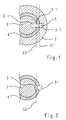
- FIG. Very schematically are a rotatable by a key rotor 2 and connected to a. For example, directly into a door housing connected and therefore not rotatable stator 3. Between the rotor 2 and stator 3 is designed as a drive output shaft output element 4. This is at least partially the axis of rotation of the rotor is rotatable and can be brought into operative connection with a driver, which is designed for actuating locking elements, so that the bolt - if necessary, if certain conditions are met - by turning of the output element 4 can be actuated.
- a driver which is designed for actuating locking elements
- Both the rotor and the stator each have a recess 2.1, 3.1, which are aligned in the drawn arrangement with a recess 4.1 in the output element.
- a coupling element 5 is located in the opening formed by these recesses.
- the coupling element 5 ball is formed. But it could also have a different shape and be, for example, a pin with a partially spherical surface or a pin.
- the operating principle is the following:
- the coupling element is displaceable by means not shown drive means of the opening. It assumes a first coupling position - or blocking position - when it is on the shear line S1, which is formed between the stator 3 and the output element. This state corresponds to the first coupling state.
- the Kupplugselement couples the output element with the stator. It prevents rotation of the output element and thus actuation of the bolt. But the coupling element does not cause a coupling between the rotor and the driven element when it is in the first coupling position. Rotor and output element and thus also rotor and bolt are thus decoupled when the coupling element is in the locked position. This is a difference from the prior art, where blocking is effected by locking the rotor to the stator.
- the arrangement shown in the figure is an example of a locking device with a coupling element 5, which is electronically controlled between a first and a second coupling position - according to the first and second coupling state -verschiebbar, wherein the coupling element 5, 5 ⁇ in a first coupling position the Output element 4 with respect to the housing blocks and in a second clutch position the output member 4 couples with the rotor 2, wherein the rotor 2 is not coupled to the output member 4 when the clutch member is in its first clutch position.
- Figure 2 shows a variant of the principle shown in Figure 1, where the coupling element 5 'is not spherical, but has a partially spherical surface.
- the recess 2.1 in the rotor is in this embodiment, for example. Limited so that the coupling element the rotor 2 and the output element 4 only couples when it is inserted into the opening to the stop. If the coupling element withdrawn slightly, it is pushed back at a torque on the rotor due to its partially spherical surface in the direction of its first coupling position.
- the hemispherical surface portion of Figure 2 may also be provided another surface shape which causes such a recoil - for example, a conical shape, etc.
- the actually to be met in this embodiment condition is that the shape of the coupling element is such that it has an area in which it is constantly rejuvenated.
- the depth of the recess 2.1 is limited in the rotor so that the coupling element in its second coupling position is also at a stop or almost at a stop, also be present in a spherical coupling element.
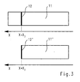
- FIG. 3 very schematically illustrates the set of all states 11.
- the coupling element is guided through the recesses and is displaceable in only one direction x; the states can therefore be characterized by the position in this direction x.
- the upper diagram of the figure shows the situation for the arrangement according to FIG. 1.
- the subset of those states in which the coupling element is in its second coupling position and enables the opening of the lock is provided with the reference numeral 12 in the FIGURE. Due to the spherical surface of the coupling element its position must be chosen very precisely so that its equator is on the shear line S2. Otherwise, the coupling element is pushed away in one or the other direction with a torque acting on the rotor. This fact has the effect that the subset 12 of the states in which release takes place is very small. With random movements, the probability almost disappears that the coupling element in the release position (the second clutch position) gets.
- the lower diagram of Figure 3 relates to the structure according to Figure 2. This differs from that of Figure 1, characterized in that the Kupplungselelement is also in its second coupling position on a stop.
- the subset 12 of the states in which a release takes place is therefore entered completely at the edge. Also in this case, it is small in comparison to the amount of all states, since the coupling element is also pushed away from the coupling position with a torque on the rotor, if it is not positioned exactly in the Kupplunslage.
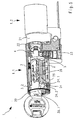
- the cylinder lock partially shown in Figures 4 and 5 has a double lock cylinder 1 with a first, provided for a door outside part cylinder 1.1 and a second, provided for a door inside partial cylinder 1.2 (optional).
- the second partial cylinder 1.2 is shown only schematically in the figure.
- the first partial cylinder 1.1 has a rotor 2 and a stator 3 surrounding it.
- the rotor is provided with a key opening 2.2.
- the driver 21 can be coupled in a manner yet darloom via a to be inserted by inserting a key 30 wing member 22 via the output member 4;
- An analogous device can also be provided for the possibly existing second partial cylinder 1.2.
- the wing element 22 is mechanically coupled to an output element 4. This can be coupled in the manner already explained either with housing parts or the stator 3 or with the rotor.
- the serving for this purpose coupling element 5 is spherical in the example shown.
- the coupling element is displaceable by drive means 23 between the first coupling layer (FIG. 4) and the second coupling layer (FIG. 5). In the first coupling position, the equator of the coupling element is located on the shearing line between the output element and the stator, in the second coupling position on the shearing line between the output element and the rotor.
- the drive means are electronically controlled.
- the cylinder lock has a not-shown electronic module and communication means for communication with a data carrier of the key 30.
- the communication means for the communication between the data carrier and electronic module can be formed in a conventional manner for non-contact communication via electromagnetic radiation, or the key can Also have contacts that are contactable via pins of the cylinder lock. Other communication options are conceivable.
- the electronic module determines - for example, also in a conventional manner - by means of data exchanged with the data medium of the key, whether the key authorizes access to the locked object. With an authorization, the electronic module controls the drive means so that they bring the coupling element in the second coupling position and release the lock ( Figure 5).
- the key holder can then cause a rotation of the output element 4 with a rotation of the key, with the coupling element in the opening, which form through recesses 2.1, 4.1 of the rotor and the output element rotates.
- the output element 4 causes via wing element 22 and driver 21 an actuation of Riegelemententen.
- movable key blocking element 24 is shown. This is mounted in the figure by a pivot pin 25 on the rotor 2 and is held with spring means 26 in its first position when no further forces act. In the first position, it blocks the rotor 2 by standing against the stator 3 in a standard orientation against rotations. By inserting a key, it can be brought into its second position against the spring force. As a result, the blocking of the rotor is released, and this can be freely rotated.
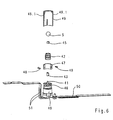
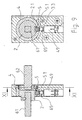
- the drive means 23 has an electric motor 40 through which a drive shaft 41 can be rotated.
- a lifting spindle 42 is placed linearly displaceable along this.
- Zwischiteil 43 is still drawn.
- Mounted on the electric motor 40 with a spring 46 is a Votriebshülse 47 with projecting through slots of the drive sleeve in bobnuten the Hubspindel 42 guide elements 48.
- the electric motor with the lifting spindle 42 and the propulsion sleeve 47 are of a bearing sleeve 49th surrounded and held.
- the spring 46 presses the propulsion sleeve 47 against a stop surface 49.1 of the bearing sleeve.
- propulsion acts on the jackscrew 42 due to the guide elements 48 projecting into the helical grooves.
- the jackscrew may be moved between a first, retracted position and a second position, in FIG For example, it protrudes partially from the bearing sleeve and the propulsion sleeve 47.
- the coupling element 5 is guided guided between its first and its second clutch position. If on the coupling element, a force in the direction of its first coupling position - ie in the figure against the bottom - so soft coupling element 5, lifting spindle 42 and propulsion sleeve 47 due to the action of the spring 46 against the spring force down.
- a force may be due to a torque acting on the rotor, if it acts when the coupling element between the two coupling layers.
- power supply cables 51 for electronically controlled energization of the electric motor as well as a base plate 50 carrying these and possibly electronic information transmission channels.
- the mechanism described here for exerting a propulsion is not the only possible way of electronically controlling propulsion.
- the skilled person will recognize many other ways in which a rotary motion of an electric motor is translated into a propulsion movement, for example, as in the present case by means of a screw gear. Variants without electric motor are also conceivable, for example a magnetic actuator.
- the role of the permanent magnet 45 will be briefly explained.
- the ferromagnetic domains in the ferromagnetic material form so that the magnetic field in the transition between the magnetized body and the ferromagnetic material is continuous. If the material and the body are separated by even a short distance, such a steady course is no longer possible, so energy must be expended to separate material and body. This causes something like a, Klebrial ', this is known to anyone who has ever played with permanent magnets.
- the permanent magnet also allows a cylinder installation position rotated in comparison to the illustrated embodiment, for example by 180 °.
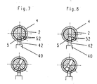
- the embodiment shown in Figures 7 and 8 differs from that of Figures 1-2 and 4-5 in that the coupling element is in the first coupling state in the interior of the rotor.
- the blocking of the output element 4 relative to the housing is effected by a blocking element, which corresponds to a propulsion means 42 - for example.
- This first coupling state is shown in FIG.
- the coupling element 5 is located completely within a circumferential line of the rotor 2. In the first coupling state shown in FIG.
- the coupling element is placed so that its equator is on the shearing line between the rotor and the output element 4 and thus couples the rotor and the output element (second coupling layer).
- the lifting spindle 42 is retracted in this second coupling state, so that the output element is rotatable.
- Drawn are still an inner and an outer support member 52, which cause the coupling element remains in the second coupling position even when the rotor is rotated and, for example. Gravity (in a rotation through 180 °) would move the coupling element against the rotor interior ,
- the mode of operation of this embodiment is the following: In the first coupling state (FIG. 8), the lifting spindle 42 blocks the output element 4 against the housing.
- the coupling element prevents rotation of the rotor, unless other means (key blocking element or the like) prevent rotation of the rotor, this is freely rotatable, but without effect (Fig. 8, bottom picture).
- a transition to the second coupling state is, for example, only possible if the system is in the aligned orientation according to FIG. 8, upper picture, which can be effected again by a key blocking element.
- the lifting spindle is electronically controlled retracted, thereby causing the coupling element is moved into the second coupling position, for example.
- the rotor By gravity, a magnetic force as in the preceding examples and / or acting on the outer of the Halteelmente 52 and of this passed over the inner support member 52 spring force.
- the rotor In the second coupling state, the rotor is rotatable and the driven element coupled with it: the bolt can be operated.
- the outer holding element 52 is located - for example, initially pressed by a spring force - within an outer circumferential line of the output element and, when the driven element is rotated away, by housing - or stator - held within this outer circumferential line. As a result, it causes, via the inner retaining element 52, that the coupling element 5 slips against the inside.
- the transition from the second to the first coupling state is possible only in the aligned in the upper image of Figure 7 oriented orientation.
- the lifting spindle presses the coupling element into the interior of the rotor, blocking the output element against the housing.
- the holding elements 52 are displaced outwards, wherein in this orientation for the outer holding element a en Maschinenende recess is present, where it is, for example. against the mentioned spring force is pressed.
- FIGS. 9, 10 and 11 An example is drawn very schematically in FIGS. 9, 10 and 11. Elements which have already been described with reference to Figures 1, 2, 4 and 5, have the same reference numerals and will not be described again here; already described modes of action are also not explained again.
- the rotor 2 is directly connected to a door handle or an effect similar means or a door knob, for example.
- a shaft 61 of the door handle or doorknob is formed as a square and engages in a corresponding opening in the rotor.
- the output element is often mounted on an axle, which lies in the installed state over an axis of a lock cylinder and on the locking means. There are then appropriate (not shown) coupling means present which couple the output element with underlying locking means.
- the axis of a door knob often corresponds to the axis of the replaced by the doorknob locking cylinder.
- the locking device is drawn in the second coupling state: the coupling element 5 protrudes into a recess in the rotor and thereby couples rotor and driven element.
- the output member 4 may be directly connected to an inside door handle or effect-like means (only a square shaft 62 drawn). Case wise. the output element in the first coupling state coupled to the housing 3, which leads to a blocking of the inside door handle.
- a channel 3.3 is provided in the housing, which forms a link and in which the coupling element 5 located in the first coupling state can move together with the output element 4 between two stops without the rotor rotating (FIG. 10).
- the coupling element 5 in the first coupling state, may, for example, be such that it does not couple the output element to the housing, for example by being pulled back so far that it no longer protrudes into the opening of the output element.
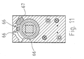
- the coupling element 5 is not spherical but formed like a pin. It is not here as a whole magnetic but has on its underside an insert 5.1 made of ferromagnetic material, for example. Of permanently magnetic material. Between the lifting spindle 42 (or the permanent magnet 45) and the coupling element 5 is a here spherical intermediate element 65 made of magnetic material.
- the intermediate element 65 has the following functions: Due to its at least partially spherical surface and thus only .punberichten bearing surfaces prevents rotational movements are transmitted from the lifting spindle to the coupling element, whereby friction losses would occur.
- the drive means can be brought into the second coupling state even if the output element and coupling means are not in the starting position, for example. Due to a partial actuation of the inner door handle or effect-like means. This is shown in FIG. In a return movement of output element and coupling means in the starting position, for example. Due to the action of a spring cause the surfaces of intermediate element 65 and coupling element 5 that the Kupplungselment 5 is shifted upward and engages in the recess 2.1 of the rotor, ie directly into the second clutch position is shifted.
- the locking device according to the invention is particularly advantageous in the case of a direct operative connection between the door handle or the door knob and the rotor, since particularly large torques can be exerted by these means.
- the inventive decoupling of rotor 2 and driven element 4 in the first coupling state is therefore particularly advantageous here.
- FIG. 11 a section through the line (XI-XI) is drawn in FIG. 9.
- Recognizable is a spring 66 for returning the output element (and possibly the inner door handle or effect-like element) and a stop element 67, which is designed as a simple insert and allows a switch between a mode with rotation to the left and a mode of rotation to the right.
- a locking cylinder which may be mechanically functioning.
Landscapes
- Physics & Mathematics (AREA)
- Electromagnetism (AREA)
- Lock And Its Accessories (AREA)
Abstract
Description
Die Erfindung betrifft eine Verriegelungsvorrichtung für ein Schliessystem. Unter "Schliesssystem" wird hier ein System mit mechanischen Elementen verstanden, welches den Zutritt oder Zugriff zu einem Objekt ermöglicht oder versperrt, je nach dem ob eine Berechtigung vorliegt oder nicht. Eine Verriegelungsvorrichtung wird insbesondere die Betätigung eines Schliesszylinders oder Schlosses durch Drehung eines Schlüssels oder eines Türknaufs, durch Betätigen eines Türdrückers oder vergleichbarer Mittel, oder automatisiert, mittels geeigneter Antriebsmittel etc. ermöglichen bzw. verhindern.The invention relates to a locking device for a locking system. "Locking system" is understood here to mean a system with mechanical elements which allows or blocks access to or access to an object, depending on whether or not there is authorization. A locking device will in particular enable or prevent the operation of a lock cylinder or lock by rotation of a key or a door knob, by operating a door handle or similar means, or automated, by means of suitable drive means, etc.
Verriegelungsvorrichtungen mit mechanisch und elektronisch - mechatronisch - gesteuerten Sperrelementen sind bekannt. Sie besitzen alle Eigenschaften von herkömmlichen rein mechanischen Verriegelungsvorrichtungen. Die zusätzliche elektronisch gesteuerte Verriegelung gewährt ausserdem die Möglichkeit, Schlüssel individuell zu aktivieren und zu sperren. Mit mechatronischen Verriegelungsvorrichtungen kann also zusätzliche Flexibilität in der Schliessorganisation erreicht werden.Locking devices with mechanically and electronically - mechatronically controlled locking elements are known. They have all the properties of conventional purely mechanical locking devices. The additional electronically controlled locking also provides the option of individually activating and locking keys. With mechatronic locking devices so additional flexibility in the Schliessorganisation can be achieved.
Die elektronisch gesteuerte Verriegelung basiert auf einer Datenübertragung zwischen einem schlüsselseitigen Elektronikmodul und einem schlosseitigen Elektronikmodul. Diese Datenübertragung kann durch Berührung - bspw. mittels elektrischer Kontakte an Schlüssel und Schloss - oder berührungslos - bspw. mittels elektromagnetischer Induktion - stattfinden. Daten können in nur eine oder in beide Richtungen übertragen werden. Im schlosseitigen oder im schlüsselseitigen Elektronikmodul wird anhand der übertragenen Daten überprüft, ob der eingesteckte Schlüssel zutrittsberechtigt ist. Wenn dies der Fall ist, so wird ein schlosseitiger Motor aktiviert, welcher elektronisch gesteuert ein Sperrelement derart bewegt, dass es den Schliesszylinder oder das Schloss freigibt.The electronically controlled locking is based on a data transmission between a key-side electronic module and a lock-side electronic module. This data transmission can be by touch - eg. By means of electrical contacts on key and lock - or non-contact - eg. By electromagnetic induction - take place. Data can be transmitted in one or both directions. In the lock-side or in the key-side electronic module is checked based on the transmitted data, whether the inserted key is authorized to access. If this is the case, a lock-side motor is activated, which electronically controls a locking element moves such that it releases the lock cylinder or the lock.
Ein solche Verriegelungsvorrichtung ist beispielsweise aus der internationalen Offenlegungsschrift WO 98/28508 oder aus der internationalen Offenlegungsschrift WO 01/21913 bekannt.Such a locking device is known, for example, from International Publication WO 98/28508 or from International Publication WO 01/21913.
Nachteilig an solchen Verriegelungsvorrichtungen gemäss dem Stand der Technik ist, dass es bei Manipulationsversuchen reicht, die durch das Sperrelement bewirkte Sperre des Schliesszylinders zu überwinden. Dies kann durch Schockeinwirkung, mittels Vibrationen, mit roher Gewalt oder sonstwie geschehen.A disadvantage of such locking devices according to the prior art is that it is sufficient in tampering attempts to overcome the barrier caused by the locking element of the lock cylinder. This can be done by shock, by vibration, by brute force or otherwise.
Um trotzdem eine hohe Sicherheit zu gewährleisten, werden solche Verriegelungsvorrichtungen oft kombiniert mit Elementen einer konventionellen, rein mechanischen Verriegelungsvorrichtung mit Zuhaltungen. Dies ist beispielsweise ebenfalls in den erwähnten Schriften WO 98/28508 und WO 01/21913 bekannt. Eine solche Kombination bringt eine erhöhte Sicherheit mit sich, sie schränkt aber die Flexibilität eines Systembetreibers aus dem folgenden Grund stark ein: Häufig sind die sicherheitsrelevantesten oder die meistfrequentierten Zugänge zu einem Objekt (bspw. einem Gebäude) mit mechatronisch/mechanischen Schlössern ausgestattet. Es existieren aber noch weitere, rein mechanisch ausgebildete Schlösser, bspw. Türen zu einzelnen Räumen im Innern des Gebäudes. Diese sollen - bei Berechtigung - mit demselben Schlüssel zu öffnen sein wie die mechatronisch/mechanischen Schlösser. Wenn in einem bestehenden Gebäude Schlösser einer ersten Schliessanlage zugeordnet sind, ist daher eine Kombination mit mechatronisch/mechanischen Schlössern einer zweiten Schliessanlage - desselben Herstellers oder eines anderen Herstellers - nicht möglich, was bspw. dann nachteilig sein kann, wenn gar kein mechatronisch/mechanisches Schliessystem des ersten Herstellers erhältlich ist. Der gleiche Nachteil existiert, wenn anlagenübergreifende Zutrittslösungen gefunden werden sollten.Nevertheless, to ensure a high level of security, such locking devices are often combined with elements of a conventional, purely mechanical locking device with tumblers. This is also known, for example, in the cited documents WO 98/28508 and WO 01/21913. Such a combination brings with it increased security, but severely restricts the flexibility of a system operator for the following reason: Frequently, the most security-relevant or most frequently accessed accesses to an object (eg a building) are equipped with mechatronic / mechanical locks. However, there are other, purely mechanically trained locks, for example. Doors to individual rooms in the interior of the building. These should - if authorized - be opened with the same key as the mechatronic / mechanical locks. If in an existing building Locks are associated with a first locking system, therefore, a combination with mechatronic / mechanical locks a second locking system - the same manufacturer or another manufacturer - not possible, which, for example, then may be disadvantageous if no mechatronic / mechanical locking system of the first manufacturer is available , The same disadvantage exists when cross-plant access solutions should be found.
Generell ist bei bestehenden mechatronischen Systemen ein Mittelweg zwischen den einander widersprechenden Anforderungen Sicherheit und Flexibilität zu finden. Oft muss zur Aufrechterhaltung der Zutrittsflexibilität die mechanische Permutationgleichschliessend ausgeführt werden, was natürlich auf Kosten der Sicherheit geht.In general, existing mechatronic systems find a middle ground between the contradictory requirements of security and flexibility. Often, in order to maintain access flexibility, the mechanical permutation must be carried out in a uniform manner, which, of course, is at the expense of safety.
Mechatronische Verriegelungsvorrichtungen mit von einem Rotor entkoppelten Abtriebselement werden in den Schriften EP1 030 011, US 5,640,863, EP 0 312 123, FR 2 801 334 und FR 2 552 809 gezeigt.Mechatronic locking devices with a driven element decoupled from a rotor are shown in EP1 030 011, US Pat. No. 5,640,863, EP 0 312 123,
Es wäre wünschenswert, eine über eine Verriegelungsvorrichtung zu verfügen, welche genügend sicher ist, um eine Entkoppelung von eventuell vorhandenen mechanischen Sicherheitselementen zu erlauben und eventuell auch ohne zusätzliche Sicherheiten durch mechanische Sicherheitselemente zu funktionieren.It would be desirable to have a locking device which is sufficiently secure to permit decoupling of any mechanical safety elements that may be present, and possibly to function without additional security by mechanical security elements.
Aufgabe der Erfindung ist es also, eine mechatronische Verriegelungsvorrichtung zu schaffen, welche gegen äussere Fremdeinflüsse, insbesondere gegen Gewalt-,. Vibrations- und/oder Schockeinwirkungen oder Magneteinwirkungen, resistent ist und ein sicheres Funktionieren gewährleistet.The object of the invention is therefore to provide a mechatronic locking device which against external foreign influences, in particular against violent. Vibratory and / or shock or magnetic effects, is resistant and ensures safe functioning.
Die Aufgabe wird gelöst durch die Verriegelungsvorrichtung und das Verfahren, wie sie durch die Patentansprüche definiert sind.The object is achieved by the locking device and the method as defined by the claims.
Die Verriegelungsvorrichtung besitzt ein Kupplungselement und ein mit Riegelmitteln in Wirkverbindung bringbares Abtriebselement. Sie kann durch elektronisch gesteuerte Antriebsmittel über Vortriebsmittel, welche das Kupplungselement bewegen, in einen ersten und einen zweiten Kupplungszustand gebracht werden. Im ersten Kupplungszustand ist der Rotor - also das durch Schlüssel, Türdrücker oder ähnliches Mittel drehbare Bauteil des Schlosses - vom Abtriebselement entkoppelt in dem Sinn, dass keine direkte Kupplung über das Kupplungselement oder andere Kupplungmittel vorhanden ist, die bewirken würden, dass eine Drehung des Rotors eine Bewegung des Abtriebselements verursacht. In seiner zweiten Kupplungslage kuppelt das Kupplungselement das Abtriebselement mit einem Rotor, der durch Schlüssel, Türdrücker, Türknauf oder ein vergleichbares Mittel oder durch einen elektrischen Antrieb betätigbar ist.The locking device has a coupling element and an output element which can be brought into operative connection with locking means. It can be brought into a first and a second clutch state by means of electronically controlled drive means via drive means which move the clutch element. In the first coupling state, the rotor - that is, the lock-rotatable member by key, door handle or similar means - is decoupled from the output member in the sense that there is no direct coupling via the coupling member or other coupling means which would cause rotation of the rotor causes a movement of the output element. In its second coupling position, the coupling element couples the output element with a rotor which can be actuated by key, door handle, doorknob or a similar means or by an electric drive.
Dieser Ansatz unterscheidet sich fundamental von bestehenden Ansätzen gemäss dem Stand der Technik. Dort ist eine Kupplung zwischen Rotor und einem Mitnehmer zum Bestätigen des Riegels entweder fest vorgesehen oder mit einfachsten Mitteln bewerkstelligbar, bspw. durch Einschieben eines schlüsselförmigen Gegenstandes. Im verriegelten Normalzustand ist der Rotor gegenüber dem Gehäuse verriegelt, wohingegen bei Stimmigkeit der mechanischen und ggf. elektronischen Codierung eine Freigabe des Rotors gegenüber dem Gehäuse erfolgt. Um das Schloss zu manipulieren, muss man also Rotor und Gehäuse entkoppeln.This approach differs fundamentally from existing approaches according to the prior art. There, a coupling between the rotor and a driver for confirming the bolt is either fixed or can be accomplished with the simplest means, for example by inserting a key-shaped object. In the locked normal state, the rotor is locked relative to the housing, whereas in the case of coherence of the mechanical and possibly electronic coding, a release of the rotor relative to the housing takes place. To manipulate the lock, you have to decouple rotor and housing.
Der erfindungsgemässe Ansatz unterscheidet sich demnach vom Stand der Technik dadurch, dass man nicht einfach Rotor und Gehäuse entkuppeln muss, sondern das Abtriebselement mit dem Rotor koppeln muss - und ggf. auch vom Gehäuse entkoppeln muss. Das erlaubt, die Kupplungsmittel - hier das Kupplungselement - auf sehr einfache Art so zu wählen, dass die Kupplung nur bei einem einzigen singulären Zustand der Kupplungsmittel zustande kommt.The approach according to the invention therefore differs from the prior art in that it is not simply necessary to decouple the rotor and the housing, but rather that The output element must be coupled to the rotor - and possibly also decoupled from the housing. This allows the coupling means - here the coupling element - to be selected in a very simple way so that the coupling only comes about in a single singular state of the coupling agent.
Man kann davon ausgehen, dass bei Manipulatiönsversuchen das Kupplungselement oder Sperrelement von seiner Ruhelage auslenkbar ist, bspw. durch Stösse. Bei einem Manipulationsversuch wird das ausgenutzt, indem durch eine Vielzahl von Stössen so lange manipuliert wird, bis sich das Sperrelement in der Freilage befindet. Gleichzeitig wird die Verriegelungsvorrichtung so beeinflusst, dass das einmal in der Freilage befindliche Sperrelement sofort in dieser fixiert wird - bspw. durch ein beständig auf den Rotor einwirkendes Drehmoment.It can be assumed that in manipulation tests the coupling element or blocking element can be deflected from its rest position, for example by means of bumps. In a manipulation attempt, this is exploited by being manipulated by a plurality of bumps until the locking element is in the free position. At the same time, the locking device is influenced so that the once located in the free-standing blocking element is fixed immediately in this - for example, by a constant acting on the rotor torque.
Die Erfordernis, dass die Kopplung nur bei einem einzigen singulären Zustand zustande kommt, verringert die Wahrscheinlichkeit, dass das Kupplungselement durch zufällige Anregungen - Stösse - überhaupt in den zweiten Kupplungszustand kommt. Und wenn das einmal der Fall sein sollte, wird durch dieselbe zufällige Anregung das Element sofort wieder aus dieser Lage entfernt. Es steht also nur ein sehr kleines Zeitfenster zur Verfügung, in welchem manipuliert werden kann. In der statistischen Mechanik wird die Anzahl aller das Ereignis (erfolgreiche Manipulation) auslösenden Zustände mit der Anzahl aller möglichen Zustände verglichen, wenn das Verhältnis klein ist, ist das Ereignis unwahrscheinlich. In der Terminologie der statistischen Mechanik erlaubt also der erfindungsgemässe Ansatz, dass der für Manipulationsversuche nur sehr wenig Phasenraum zur Verfügung steht. Ausserdem ist es nicht möglich, das Kupplungselement durch beständiges Ausüben eines Drehmoments auf den Rotor zu fixieren, sobald es in der zweiten Kupplungslage ist, da der Rotor nicht über das Abtriebselement mit dem Gehäuse gekoppelt ist sondern frei drehbar oder mit einem anderen, vom Kupplungselement unabhängigen Mittel fixiert ist.The requirement that the coupling only occur in a single singular state reduces the likelihood that the coupling element will ever come into the second coupling state by accidental excitations - shocks. And if that happens to be the case, the same random stimulus immediately removes the element from that location. So there is only a very small time window available in which to manipulate. In statistical mechanics, the number of states triggering the event (successful manipulation) is compared with the number of all possible states, and if the ratio is small, the event is unlikely. Thus, in the terminology of statistical mechanics, the approach according to the invention allows only very little phase space to be available for manipulation attempts. Moreover, it is not possible to fix the coupling element by constantly exerting a torque on the rotor, as soon as it in the second Clutch position is because the rotor is not coupled via the output element to the housing but is freely rotatable or fixed with another, independent of the coupling element means.
Durch eine rücktreibende Kraft, welche bewirkt, dass das Kupplungselement tendenziell von der dem zweiten Kupplungszustand entsprechenden zweiten Kupplungslage weg bewegt wird, kann die Wahrscheinlichkeit, dass das Kupplungselement zufällig in die zweite Kupplungslage gelangt, weiter verringert werden.By a restoring force, which causes the coupling element tends to be moved away from the second coupling position corresponding to the second coupling state, the probability that the coupling element accidentally gets into the second coupling position, can be further reduced.
Die mechanische Entkopplung von Rotor und Abtriebselement im ersten Kupplungszustand bringt auch den Vorteil mit sich, dass auch durch gewaltsames Drehen des Rotors das Schloss nicht betätigt werden kann: Der Rotor dreht höchstens leer.The mechanical decoupling of the rotor and output element in the first coupling state also has the advantage that even by violent rotation of the rotor, the lock can not be operated: The rotor rotates at most empty.
Gemäss einer Ausführungsform ist im ersten Kupplungszustand das Abtriebselement gegenüber einem Gehäuse versperrt. Damit wird es noch zusätzlich gegen Drehungen gesperrt.According to one embodiment, in the first coupling state, the output element is blocked with respect to a housing. Thus it is additionally locked against rotation.
Das Kupplungselement kann eine mindestens teilweise sphärische Oberfläche aufweisen - und beispielsweise als Kugel ausgebildet sein. Dadurch wird die Anzahl der Positionen, in welcher es kuppelt, minimiert - was wie oben beschrieben vorteilhaft ist. Es besteht dann das Erfordernis, dass eine Scherlinien zwischen den zu kuppelnden Elementen und der Äquator des Kupplungselementes aufeinander ausgerichtet sind. Wenn der Äquator des Kupplungselementes oberhalb oder unterhalb der Scherlinie ist, wird das Kupplungselement durch Kraftausübung auf eines der zu kuppelnden Elemente von der Kupplungslage weg geschoben.The coupling element may have an at least partially spherical surface - and be formed for example as a ball. This minimizes the number of positions in which it engages - which is advantageous as described above. There is then the requirement that a shear lines between the elements to be coupled and the equator of the coupling element are aligned. When the equator of the coupling element is above or below the shear line, the coupling element is pushed away from the coupling layer by exerting force on one of the elements to be coupled.
Bevorzugt ist das Kupplungselement weder an das Gehäuse noch an den Rotor gekoppelt. Das Kupplungselement kann dann in seiner zweiten Kupplungslage bei einer Drehbewegung des Rotors mitgedreht werden. Es liegt dabei bspw. in einer Öffnung, welche durch Aussparungen im Rotor und im Abtriebselement gebildet wird. Auch zum Abtriebselement besteht beispielsweise keine feste mechanische Kopplung wie bspw. ein Scharnier oder Formschluss sondern höchstens eine Führung durch eine Aussparung in diesem, d.h. auch wenn das Kupplungselement immer mit dem Abtriebselement mitdrehbar ist, ist es doch ein mechanisch unabhängiges Element. Es kann vorgesehen sein, dass vor dem Abziehen des Schlüssels der Rotor in seine ursprüngliche Orientierung zurück gebracht werden muss, also nur um ganzzahlige Drehungen gedreht werden kann.Preferably, the coupling element is neither coupled to the housing nor to the rotor. The coupling element can then be rotated in its second coupling position during a rotational movement of the rotor. It is, for example, in an opening which is formed by recesses in the rotor and the output element. For example, there is also no fixed mechanical coupling, such as a hinge or positive locking, but at most a guide through a recess in the same, that is to say the output element. Even if the coupling element is always mitdrehbar with the output element, but it is a mechanically independent element. It can be provided that before the removal of the key, the rotor must be returned to its original orientation, so it can only be rotated by integer turns.
Die Antriebsmittel können bspw. das Kupplungselement zwischen zwei Kupplungslagen - entsprechend den zwei Kupplungszuständen - verschieben: In der ersten Kupplungslage koppelt das Kupplungselement Gehäuse und Abtriebselement, während es keine Kopplung zwischen Rotor und Abtriebselement bewirkt. In der zweiten Kupplungslage koppelt es Rotor und Abtriebselement, bewirkt aber keine Kopplung zwischen Gehäuse und Abtriebselement.The drive means can, for example, the coupling element between two coupling layers - according to the two coupling states - move: In the first coupling position, the coupling element couples the housing and driven element, while it causes no coupling between the rotor and the driven element. In the second coupling position, it couples the rotor and the output element, but does not cause any coupling between the housing and the output element.
Alternativ dazu kann ein als Blockierelement dienendes Vortriebsmittel des Antriebsmittels das Abtriebselement im ersten Kupplungszustand gegenüber dem Gehäuse versperren. Im zweiten Kupplungszustand kuppelt das Kupplungselement Rotor und Abtriebshülse. Dabei sind Blockierelement und Kupplungselement so ausgebildet und angeordnet, dass das Blockierelement, wenn es vom zweiten zum ersten Kupplungszustand bewegt wird, gleichzeitig durch direkte oder indirekte Einwirkung das Kupplungselement von der kuppelnden Lage weg bewegt.Alternatively, serving as a blocking element propulsion means of the drive means obstruct the output member in the first coupling state relative to the housing. In the second coupling state, the coupling element couples rotor and output sleeve. In this case, blocking element and coupling element are designed and arranged so that the blocking element, when it is moved from the second to the first coupling state, at the same time by direct or indirect action, the coupling element moves away from the coupling position.
Eine weitere Alternative sieht vor, dass das Abtriebselement auch im ersten Kupplungszustand nicht gegen das Gehäuse versperrt wird. Dies ist dann vorteilhaft, wenn das Abtriebselement bspw. mit einem inneren Türdrücker fest verbunden ist. In dieser Ausführungsform wird einerseits sichergestellt, dass eine im Innern des zu verschliessenden Objektes befindliche Person das Objekt_immer verlassen kann. Andererseits stellt diese direkte Kopplung zwischen Abtriebselement und innerem Türdrücker auch einen gewissen Schutz vor Manipulationen dar - immerhin muss der innere Türdrücker bei jedem Manipulationsversuch mitbewegt werden.Another alternative provides that the output element is not blocked against the housing in the first coupling state. This is advantageous if the output element is, for example, firmly connected to an inner door handle. In this embodiment, on the one hand, it is ensured that a person located in the interior of the object to be closed can leave the object. On the other hand, this direct coupling between output element and inner door handle also provides some protection against manipulation - after all, the inner door handle must be moved with each manipulation attempt.
Als Antriebsmittel kann ein Elektromotor mit einer Hubspindel verwendet werden. Elektromotoren sind im Vergleich zu Magnetstellgliedern relativ sparsame Stromkonsumenten. Zudem sind sie aufgrund der Bauweise weitgehend vibrations-, schock- und magnetresistent.As drive means, an electric motor can be used with a lifting spindle. Electric motors are relatively economical power consumers compared to magnetic actuators. In addition, they are due to the design largely vibration, shock and magnetic resistant.
Das Kupplungselement kann durch das Antriebsmittel ,quasi-zwangsgeführt` oder gar ganz zwangsgeführt verschiebbar sein. Das bedeutet, dass die Position des Kupplungselementes zwischen der ersten und der zweiten Kupplungslage jederzeit durch das Antriebsmittel definiert wird, bspw. indem es mit dem Vortriebsmittel des Antriebsmittels verbunden ist. Im Falle der quasi-Zwangsführung ist diese Verbindung nur durch einen gewissen Kraftaufwand zu lösen; es kann bspw. sein, dass das Vortriebsmittel und/oder das Kupplungselment ein permanentes magnetisches Moment aufweist und dadurch das Kupplungselement am Vortriebsmittel haftet. Im Falle der Zwangsführung ist die Verbindung so fest, dass sie durch normale Stösse gar nicht lösbar ist. Beispielsweise wird das Kupplungselement durch mechanische Verbindungen am Vortriebsmittel fixiert; die mechanischen Verbindungen werden bspw. gelöst, sobald sich das Kupplungsmittel in der zweiten Kupplungslage befindet.The coupling element can be displaceable by the drive means, quasi-positively guided` or even completely positively guided. This means that the position of the coupling element between the first and the second clutch layer is defined at all times by the drive means, for example by being connected to the drive means of the drive means. In the case of quasi-forced operation, this connection can be solved only by a certain amount of force; it may be, for example, that the propulsion means and / or the Kupplungselment has a permanent magnetic moment and thereby the coupling element adheres to the propulsion medium. In the case of positive guidance, the connection is so strong that it is not solvable by normal bumps. For example, the coupling element is fixed by mechanical connections on the propulsion medium; The mechanical connections are, for example, solved as soon as the coupling agent is in the second coupling position.
Die Verriegelungsvorrichtung kann also so ausgebildet sein, dass sich das Kupplungselement immer auf einer von zwei vorgegebenen Bahnen befindet: auf der ersten Bahn quasi-zwangsgeführt oder zwangsgeführt zwischen der ersten und der zweiten Kupplungslage, und auf der zweiten Bahn durch den Rotor mitgedreht und relativ zu diesem in konstanter Position um eine Achse des Rotors herum.The locking device can thus be designed so that the coupling element is always on one of two predetermined paths: on the first path quasi-positively guided or positively guided between the first and the second clutch position, and rotated on the second path through the rotor and relative to in a constant position about an axis of the rotor.
Das Antriebsmittel kann mit Federmitteln versehen sein, die so ausgebildet und angeordnet sind, dass das zwischen der ersten Kupplungslage und der zweiten Kupplungslage befindliche Kupplungselement durch mechanisches Einwirken entgegen einer Federkraft in Richtung der ersten Kupplungslage bewegbar ist. Damit kann Schäden durch gewaltsame Manipulationsversuche und beim Ausfall des Antriebs vorgebeugt werden. Wenn sich das Kupplungselement in einer - undefinierten - Lage zwischen der ersten und der zweiten Kupplungslage befindet, und Kraft auf eine Scherlinie ausgeübt wird, weicht das Kupplungselement in Richtung der ersten Kupplungslage aus, ohne dass Schäden entstehen würden.The drive means may be provided with spring means which are designed and arranged such that the coupling element located between the first coupling position and the second coupling position can be moved by mechanical action counter to a spring force in the direction of the first coupling position. This can prevent damage caused by violent manipulation attempts and failure of the drive. When the coupling element is in an undefined position between the first and second coupling layers, and force is applied to a shear line, the coupling element deviates toward the first coupling layer without causing any damage.
Verriegelungsvorrichtung kann - für den Fall, dass sie mit einem Schliesszylinder verwendet wird - ein Schlüsselblockierelement aufweisen, das durch Einführen des Schlüssels in die Schlüsselöffnung von einer ersten Lage zu einer zweiten Lage bewegbar ist, wobei es in der zweiten Lage ein Herausziehen des Schlüssels nur bei bestimmten, vorgegebenen Ausrichtungen des Rotors erlaubt. Das erlaubt einerseits dem Benutzer, in an sich bekannter Art eine Türe zu öffnen, indem er am nicht vertikal ausgerichteten Schlüssel zieht. Andererseits kann dadurch gewährleistet sein, dass das System bei entferntem Schlüssel immer in einer definierten Lage ist, in welcher das Kupplungselement zwischen den zwei Kupplungslagen verschiebbar ist. Es kann ausserdem vorgesehen sein, dass das Schlüsselblockierelement den Rotor in der ersten Lage gegen Drehungen blockert, damit dieser nicht durch einen Schraubenzieher oder ähnliche Mittel oder durch zufällig induzierte Bewegungen von seiner definierten Lage weg bewegt werden kann. Bei Versuchen, den Rotor mit einem Schraubenzieher o.ä. und mit viel Kraft zu bewegen, wird allenfalls das Schlüsselblockerelement beschädigt, wegen der mechanischen Entkopplung von Rotor und Gehäuse aber niemals die für das Betätigen des Riegels wesentlichen Elemente.Locking device may - in the event that it is used with a lock cylinder - have a key blocking element which is movable by inserting the key in the key opening from a first position to a second position, wherein it in the second position, a withdrawal of the key only at certain, predetermined orientations of the rotor allowed. On the one hand, this allows the user to open a door in a manner known per se by pulling on the key which is not oriented vertically. On the other hand, it can be ensured that the system is always in a defined position with the key removed, in which the coupling element between the two coupling layers is displaceable. It may also be provided that the key blocking element blocks the rotor in the first position against rotation so that it can not be moved away from its defined position by a screwdriver or similar means or by randomly induced movements. When trying to use the rotor with a screwdriver or similar and to move with a lot of force, the Schlüsselblockerelement is damaged at best, because of the mechanical decoupling of rotor and housing but never the essential elements for operating the bolt elements.
Das Schlüsselblockierelement - zusammen mit dem Kupplungselement - bewirkt, dass insgesamt drei definierte Zustände vorhanden sind:
- 1. Kein Schlüssel steckt: Erster Kupplungszustand, und das Schlüsselblockierelement blockiert den Rotor
- 2. Ein unberechtigter Schlüssel steckt: Erster Kupplungszustand, und das Schlüsselblockierelement gibt den Rotor frei. Der Rotor ist frei drehbar, er bewirkt aber keine Betätigung des Riegels. Der Schlüssel kann nur in einer definierten Position des Rotors herausgezogen werden.
- 3. Der berechtigte Schlüssel steckt: Zweiter Kupplungszustand, der Rotor ist drehbar, und seine Drehung bewirkt ein Betätigen des Riegels.
- 1. No key is in: First clutch state, and the key blocking element blocks the rotor
- 2. An unauthorized key is: First clutch state, and the key blocking element releases the rotor. The rotor is freely rotatable, but it causes no operation of the bolt. The key can only be pulled out in a defined position of the rotor.
- 3. The authorized key is: second clutch state, the rotor is rotatable, and its rotation causes the bolt to be actuated.
Das Schlüsselblockierelement kann bspw. ein Kipphebel sein, der mit einer Feder verbunden ist, die eine Rückstellkraft hin zur ersten Lage bewirkt.The key blocking element may be, for example, a rocker arm which is connected to a spring which causes a restoring force to the first position.
Die zusätzliche Sicherheit, welche durch die vorstehenden Elemente bewirkt wird, hat zur Folge, dass die Verriegelungsvorrichtung bspw. ohne rein mechanisch betätigbare Zuhaltungen auskommt. Damit kann eine erfindungsgemässe Verriegelungsvorrichtung mit irgendwelchen bestehenden Schliesssystemen kombiniert werden und anlagenübergreifend zum Einsatz kommen. Die Verriegelungsvorrichtung erlaubt eine Verbindung von mehreren Anlagen und einen Einsatz in mehreren Anlagen mit einem systemneutralen Schlüssel.The additional security, which is caused by the above elements, has the consequence that the locking device, for example, manages without purely mechanically actuated tumblers. This can be a locking device according to the invention with any existing locking systems combined and used across plants. The locking device allows a connection of multiple systems and a deployment in multiple systems with a system-neutral key.
Selbstverständlich kann eine erfindungsgemässe Verriegelungsvorrichtung aber auch zusätzlich noch mechanische Zuhaltungen aufweisen.Of course, a locking device according to the invention may, however, additionally also have mechanical tumblers.
Die erfindungsgemässe Verriegelungsvorrichtung ist in dieser Ausführungsform also systemneutral: mechanische und mechantronische Systemkomponenten sind vollständig trennbar.The inventive locking device is thus system neutral in this embodiment: mechanical and mechantronic system components are completely separable.
Im Folgenden werden noch bevorzugte Ausführungsformen der Erfindung anhand von Zeichnungen näher beschrieben. Es zeigen:
Figur 1 schematisch einen Schnitt durch Elemente einer erfindungsgemässen Verriegelungsvorrichtung.Figur 2 ebenfalls schematisch einen Schnitt durch Elemente einer weiteren Ausführungsform einer erfindungsgemässen Verriegelungsvorrichtung.Figur 3 schematisch die möglichen Zustände für das Kupplungselement in den Anordnungengemäss den Figuren 1und 2.Figur 4 eine Ansicht, teilweise im Schnitt, von Elementen eines Zylinderschlosses mit einer Ausführungsform der erfindungsgemässen Verriegelungsvorrichtungwobei das Kupplungselement in der ersten Kupplungslage ist.Figur 5 dieAnsicht gemäss Figur 4, wobei ein Schlüssel in die Schlüsselöffung eingeschoben ist und sich das Kupplungselement in der zweiten Kupplungslage befindet.- Figur 6 eine Explosionsdarstellung von Bestandteilen der Antriebsmittel.
- Figuren 7 und 8 schematisch einen Schnitt durch eine weitere Ausführungsform in zwei Kupplungszuständen.
- Figuren 9 und 10 einen Querschnitt und einen Längsschnitt (schematisch) durch ein -Schloss mit einer erfindungsgemässen Verriegelungsvorrichtung, in zwei Kupplungszuständen
Figur 11 einen weiteren Querschnitt durch das Schloss gemäss Figuren 9 und 10.
- 1 shows schematically a section through elements of a locking device according to the invention.
- Figure 2 also schematically a section through elements of another embodiment of a locking device according to the invention.
- FIG. 3 schematically shows the possible states for the coupling element in the arrangements according to FIGS. 1 and 2.
- Figure 4 is a view, partly in section, of elements of a cylinder lock with an embodiment of the inventive Locking device, wherein the coupling element is in the first coupling position.
- Figure 5 shows the view according to Figure 4, wherein a key is inserted into the keyhole and the coupling element is in the second coupling position.
- Figure 6 is an exploded view of components of the drive means.
- Figures 7 and 8 schematically shows a section through a further embodiment in two coupling states.
- Figures 9 and 10 a cross section and a longitudinal section (schematically) through a lock with a locking device according to the invention, in two coupling states
- 11 shows a further cross section through the lock according to FIGS. 9 and 10.
Ein einer Ausführungsform der Erfindung zugrunde liegendes Prinzip ist in der Figur 1 gezeigt. Sehr schematisch sind ein durch einen Schlüssel drehbarer Rotor 2 und ein mit einem bspw. direkt in eine Türe eingebauten Gehäuse verbundenen und daher nicht drehbaren Stator 3. Zwischen Rotor 2 und Stator 3 befindet sich ein als Abtriebshülse ausgebildetes Abtriebselement 4. Dieses ist mindestens Teilweise um die Drehachse des Rotors drehbar und ist mit einem Mitnehmer in Wirkverbindung bringbar, welcher zum Betätigen von Riegelelementen ausgebildet ist, so, dass der Riegel - gegebenenfalls, wenn gewisse Voraussetzungen erfüllt sind - durch drehen des Abtriebselementes 4 betätigt werden kann. Sowohl der Rotor als auch der Stator besitzen je eine Aussparung 2.1, 3.1, welche in der gezeichneten Anordnung mit einer Aussparung 4.1 im Abtriebselement fluchten. Ein Kupplungselement 5 befindet sich in der Öffnung, welche durch diese Aussparungen gebildet wird. In der Figur ist das Kupplungselement 5 Kugel ausgebildet. Es könnte aber auch eine andere Form haben und beispielsweise ein Zapfen mit einer teilweise sphärischen Oberfläche oder ein Stift sein. Das Funktionsprinzip ist das Folgende: Das Kupplungselement ist durch nicht dargestellte Antriebsmittel der Öffnung verschiebbar. Es nimmt eine erste Kupplungslage - oder Sperrlage - ein, wenn es sich auf der Scherlinie S1 befindet, welche zwischen dem Stator 3 und den Abtriebselement gebildet wird. Dieser Zustand entspricht dem ersten Kupplungszustand. In seiner ersten Kupplungslage kuppelt das Kupplugselement das Abtriebselement mit dem Stator. Es verhindert ein Drehen des Abtriebselements und damit ein Betätigen des Riegels. Das Kupplungselement bewirkt aber keine Kupplung zwischen Rotor und Abtriebselement, wenn es in der ersten Kupplungslage ist. Rotor und Abtriebselement und damit auch Rotor und Riegel sind also entkoppelt, wenn das Kupplungselement in der Sperrlage befindet. Dies ist ein Unterschied zum Stand der Technik, wo eine Sperrung dadurch bewirkt wird, dass der Rotor gegenüber dem Stator gesperrt wird.A principle underlying an embodiment of the invention is shown in FIG. Very schematically are a rotatable by a
In einer zweiten Kupplungslage - oder Freilage - ist das Kupplungselement 5, wenn es sich auf der Scherlinie S2 zwischen dem Rotor und dem Abtriebselement befindet. Dies ist der zweite Kupplungszustand.In a second coupling position - or Freilage - is the
Die in der Figur gezeigte Anordnung ist ein Beispiel für eine Verriegelungsvorrichtung mit einem Kupplungselement 5, das elektronisch gesteuert zwischen einer ersten und einer zweiten Kupplungslage - entsprechend dem ersten und zweiten Kupplungszustand -verschiebbar ist, wobei das Kupplungselement 5, 5` in einer ersten Kupplungslage das Abtriebselement 4 gegenüber dem Gehäuse sperrt und in einer zweiten Kupplungslage das Abtriebselement 4 mit dem Rotor 2 kuppelt, wobei der Rotor 2 nicht mit dem Abtriebselement 4 gekuppelt ist, wenn sich das Kupplungselement in seiner ersten Kupplungslage befindet.The arrangement shown in the figure is an example of a locking device with a
Figur 2 zeigt eine Variante des in Figur 1 gezeigten Prinzips, wo das Kupplungselement 5' nicht kugelförmig ist, sondern eine nur teilweise sphärische Oberfläche besitzt. Die Aussparung 2.1 im Rotor ist in dieser Ausführungsform bspw. so begrenzt, dass das Kupplungselement den Rotor 2 und das Abtriebselement 4 nur kuppelt, wenn es bis zum Anschlag in die Öffnung eingeführt ist. Ist das Kupplungselement etwas zurückgezogen, wird es bei einem Drehmoment auf den Rotor aufgrund seiner teilweise sphärischen Oberfläche zurück in Richtung seiner ersten Kupplungslage gestossen.Figure 2 shows a variant of the principle shown in Figure 1, where the coupling element 5 'is not spherical, but has a partially spherical surface. The recess 2.1 in the rotor is in this embodiment, for example. Limited so that the coupling element the
Anstelle des halbkugelförmigen Oberflächenabschnittes der Figur 2 kann auch eine andere Oberflächenform vorgesehen sein, welche ein solche Zurückstossen bewirkt - bspw. eine Kegelform etc. Die eigentlich in dieser Ausführungsform zu erfüllende Bedingung ist, dass die Form des Kupplungselementes so ist, dass es einen Bereich aufweist, in welchem es sich stetig verjüngt.Instead of the hemispherical surface portion of Figure 2 may also be provided another surface shape which causes such a recoil - for example, a conical shape, etc. The actually to be met in this embodiment condition is that the shape of the coupling element is such that it has an area in which it is constantly rejuvenated.
Natürlich kann das Merkmal, dass die Tiefe der Aussparung 2.1 im Rotor so begrenzt ist, dass das Kupplungselement in seiner zweiten Kupplungslage gleichzeitig auch an einem Anschlag oder fast an einem Anschlag ist, auch bei einem kugelförmigen Kupplungselement vorhanden sein.Of course, the feature that the depth of the recess 2.1 is limited in the rotor so that the coupling element in its second coupling position is also at a stop or almost at a stop, also be present in a spherical coupling element.
Anhand von Figur 3 wird nun dargestellt, wie die Ausführungsformen gemäss Figuren 1 und 2 dazu beitragen, dass bei Manipulationsversuchen mit zufälligen Bewegungen des Kupplungselement die Wahrscheinlichkeit für ein erfolgreiches Öffnen des Schlosses sehr gering ist und gegen 0 geht.With reference to FIG. 3, it will now be shown how the embodiments according to FIGS. 1 and 2 contribute to random manipulation attempts Movements of the coupling element the probability of a successful opening of the lock is very low and goes to 0.
Die Figur 3 stellt sehr schematisch die Menge aller Zustände 11 dar. In der Anordnung der Figuren 1 und 2 wird das Kupplungselement durch die genannten Aussparungen geführt und ist nur in einer Richtung x verschiebbar; die Zustände können also durch die Position in dieser Richtung x charakterisiert werden. Das obere Diagramm der Figur zeigt die Situation für die Anordnung gemäss Figur 1. Die Untermenge derjenigen Zustände, in welcher das Kupplungselement in seiner zweiten Kupplungslage ist und das Öffnen des Schlosses ermöglicht ist in der Figur mit dem Bezugszeichen 12 versehen. Aufgrund der sphärischen Oberfläche des Kupplungselementes muss seine Position sehr präzis so gewählt sein, dass sich sein Äquator auf der Scherlinie S2 befindet. Andernfalls wird das Kupplungselement bei einem auf den Rotor wirkenden Drehmoment in die eine oder andere Richtung weggestossen. Diese Tatsache wirkt sich so aus, dass die Untermenge 12 der Zustände, in welcher eine Freigabe erfolgt, sehr klein ist. Bei zufälligen Bewegungen verschwindet die Wahrscheinlichkeit fast, dass das Kupplungselement in die Freigabe-Lage (die zweite Kupplungslage) gerät.FIG. 3 very schematically illustrates the set of all states 11. In the arrangement of FIGS. 1 and 2, the coupling element is guided through the recesses and is displaceable in only one direction x; the states can therefore be characterized by the position in this direction x. The upper diagram of the figure shows the situation for the arrangement according to FIG. 1. The subset of those states in which the coupling element is in its second coupling position and enables the opening of the lock is provided with the
Das untere Diagramm der Figur 3 bezieht sich auf den Aufbau gemäss Figur 2. Dieser unterscheidet sich von demjenigen von Figur 1 dadurch, dass das Kupplungselelement in seiner zweiten Kupplungslage gleichzeitig auch an einem Anschlag ist. Die Untermenge 12 der Zustände, in welcher eine Freigabe erfolgt, ist daher ganz am Rand eingetragen. Auch in diesem Fall ist sie klein im Vergleich zur Menge aller Zustände, da das Kupplungelement ebenfalls bei einem Drehmoment auf den Rotor von der Kupplungslage weggedrückt wird, wenn es nicht exakt in der Kupplunslage positioniert ist.The lower diagram of Figure 3 relates to the structure according to Figure 2. This differs from that of Figure 1, characterized in that the Kupplungselelement is also in its second coupling position on a stop. The
Die Figur 3 erklärt also, wie durch die beschriebenen Massnahmen die Erfolgswahrscheinlichkeit bei Manipulationsversuchen schon durch reine Statistik auf einen sehr kleinen Wert gebracht wird. Zusätzliche Massnahmen können diese Erfolgswarscheinlichkeit weiter verringern.
- 1. Es wird dafür gesorgt, dass bei Anregungen des Kupplungselements durch Stösse die Geschwindigkeit des Kupplungselementes immer gross ist, wenn es in derjenigen Position ist, die der zweiten Kupplungslage entspricht. In den hier beschriebenen Beispielen geschieht das dadurch, dass das Kupplungelement in seiner ersten Kupplungslage mit einer gewissen Kraft fixiert ist - es klebt quasi in der ersten Kupplungslage. Es kann dann nur durch einen sehr massiven Stoss überhaupt von dieser entfernt werden, bei einem solchen ist dann die Geschwindigkeit des sich lösenenden Kupplungelementes sehr gross. In der Ausführungsform gemäss Figur 2 wird es ausserdem am Anschlag sofort reflektiert und schnellt in Richtung erste Kupplungslage zurück. Die Heftwirkung, mit welcher das Kupplungselement in der ersten Kupplungslage quasi fixiert wird, kann bspw. durch einen Ferromagneten bewirkt werden, es können aber auch andere Mittel benutzt werden, bspw. ein Klemmen oder Kleben oder klettverschlussähnliche Mechanismen. Weitere Mechanismen sind denkbar, wie bspw. die im US-
Patent 4 103 526 für mechanischen Zuhaltungen beschriebenen T-Nuten oder schwalbenschanzförmigen Nuten. - 2. Eine rücktreibende Kraft, wie sie bspw. in der bereits erwähnten Publikation WO 98/28508 beschrieben ist. Bezüglich deren Effekt sei auf diese Publikation verwiesen. Die Quelle der rücktreibenden Kraft kann bspw. ebenfalls ein Ferromagnet sein.
- 1. It is ensured that when suggestions of the coupling element by impacts the speed of the coupling element is always large when it is in the position corresponding to the second coupling position. In the examples described here, this is done by the fact that the coupling element is fixed in its first coupling position with a certain force - it sticks virtually in the first coupling position. It can only be removed by a very massive shock at all of this, then in such a speed of the loosening coupling element is very large. In the embodiment according to FIG. 2, it is also immediately reflected at the stop and springs back in the direction of the first coupling position. The stitching action, with which the coupling element is quasi fixed in the first coupling position, can for example be effected by a ferromagnet, but other means can also be used, for example a clamping or gluing or velcro-like mechanisms. Further mechanisms are conceivable, such as, for example, the T-slots or dovetail grooves described in US Pat. No. 4,103,526 for mechanical tumblers.
- 2. A restoring force, as described, for example, in the already mentioned publication WO 98/28508. Regarding their effect, please refer to this publication. The source of the restoring force may, for example, also be a ferromagnet.
Das in den Figuren 4 und 5 teilweise dargestellte Zylinderschloss besitzt einen doppelten Schliesszylinder 1 mit einem ersten, für einen Türaussenseite vorgesehenen Teilzylinder 1.1 und einem zweiten, für eine Türinnenseite vorgesehenen Teilzylinder 1.2 (optional). Der zweite Teilzylinder 1.2 ist in der Figur lediglich schematisch dargestellt. Der erste Teilzylinder 1.1 besitzt einen Rotor 2 und einen diesen umgebenden Stator 3. Der Rotor ist mit einer Schlüsselöffnung 2.2 versehen. Ebenfalls dargestellt ist ein Mitnehmer 21, welcher mit nicht dargestellten Riegelemenenten in Verbindung bringbar ist. Der Mitnehmer 21 kann in noch darzustellender Weise über ein durch Einführen eines Schlüssels 30 einzuschiebendes Flügelelement 22 über das Abtriebselement 4 gekoppelt werden; eine analoge Einrichtung kann auch für den eventuell vorhandenen zweiten Teilzylinder 1.2 vorgesehen sein. Das Flügelelement 22 ist mechanisch mit einem Abtriebselement 4 gekoppelt. Dieses kann in bereits erläuterter Weise entweder mit Gehäuseteilen bzw. dem Stator 3 oder mit dem Rotor gekoppelt werden. Das dazu dienende Kupplungselement 5 ist im dargestellten Beispiel kugelförmig ausgebildet. Das Kupplungelement ist durch Antriebsmittel 23 zwischen der ersten Kupplungslage (Figur 4) und der zweiten Kupplungslage (Figur 5) verschiebbar. In der ersten Kupplungslage befindet sich der Äquator des Kupplungelements auf der Scherlinie zwischen Abtriebselement und Stator, in der zweiten Kupplungslage auf der Scherlinie zwischen Abtriebselement und Rotor.The cylinder lock partially shown in Figures 4 and 5 has a
Die Antriebsmittel werden elektronisch gesteuert. Für die Steuerung besitzt das Zylinderschloss ein nicht dargestelltes Elektronikmodul und Kommunikationsmittel zur Kommunikation mit einem Datenträger des Schlüssels 30. Die Kommunikationsmittel für die Kommunikation zwischen Datenträger und Elektronikmodul können in an sich bekannter Art für eine berührungslose Kommunikation via elektromagnetischer Strahlung ausgebildet sein, oder der Schlüssel kann auch über Kontakte verfügen, welche über Kontaktstifte des Zylinderschlosses kontaktierbar sind. Weitere Kommunikationsmöglichkeiten sind denkbar. Das Elektronikmodul bestimmt - bspw. ebenfalls in an sich bekannter Art - anhand von mit dem Datenträger des Schlüssels ausgetauschten Daten, ob der Schlüssel zum Zutritt zum verschlossenen Objekt berechtigt. Bei einer Berechtigung steuert das Elektronikmodul die Antriebsmittel so, dass diese das Kupplungselement in die zweite Kupplungslage bringen und das Schloss freigeben (Figur 5). Der Schlüsselinhaber kann dann mit einer Drehung des Schlüssels eine Drehung des Abtriebselementes 4 bewirken, wobei sich das Kupplungselement in der Öffnung, welche durch Aussparungen 2.1, 4.1 des Rotors und des Abtriebselementes bilden, mitdreht. Das Abtriebselement 4 bewirkt über Flügelelement 22 und Mitnehmer 21 eine Betätigung von Riegelemententen.The drive means are electronically controlled. For the control, the cylinder lock has a not-shown electronic module and communication means for communication with a data carrier of the key 30. The communication means for the communication between the data carrier and electronic module can be formed in a conventional manner for non-contact communication via electromagnetic radiation, or the key can Also have contacts that are contactable via pins of the cylinder lock. Other communication options are conceivable. The electronic module determines - for example, also in a conventional manner - by means of data exchanged with the data medium of the key, whether the key authorizes access to the locked object. With an authorization, the electronic module controls the drive means so that they bring the coupling element in the second coupling position and release the lock (Figure 5). The key holder can then cause a rotation of the
Nahe bei der Schlüsselöffnung 2.2 ist noch ein als Kipphebel ausgebildetes, zwischen einer ersten Lage (Figur 4) und einer zweiten Lage (Figur 5) bewegbares Schlüsselblockierelement 24 dargestellt. Dieses ist in der Figur durch einen Drehzapfen 25 am Rotor 2 gelagert und wird mit Federmitteln 26 in seiner ersten Lage gehalten, wenn keine weiteren Kräfte einwirken. In der ersten Lage blockiert es durch Anstehen am Stator 3 den Rotor 2 in einer Standardorientierung gegen Drehungen. Durch Einschieben eines Schlüssels kann es entgegen der Federkraft in seine zweite Lage gebracht werden. Dadurch löst sich die Blockierung des Rotors, und dieser kann frei gedreht werden. Sobald der Rotor nicht mehr in seiner Standardorientierung ist, wird durch Anstehen eines ersten Fortsatzes 24.1 an einer Stirnfläche 3.2 des Stators verhindert, dass das Schlüsselblockierelement 24 zurück in seine erste Lage gelangen kann. Gleichzeitig verhindert ein zweiter Fortsatz 24.2 des Schlüsselblockerelements 24, im Zusammenspiel mit einem Vorsprung 30.1 des Schlüssels 30, dass dieser herausgezogen werden kann.Close to the key opening 2.2 is still designed as a rocker, between a first layer (Figure 4) and a second layer (Figure 5) movable
Selbstverständlich kann auch auf andere Weise sichergestellt werden, dass die Kupplungsachse synchronisiert wird, bspw. - in an sich bekannter Art - durch mechanische Zuhaltungen.Of course, it can be ensured in other ways that the coupling axis is synchronized, for example. - In a conventional manner - by mechanical tumblers.
Anhand der Figur 6 wird noch das Antriebsmittel 23 genauer beschrieben. Es besitzt einen Elektromotor 40, durch welchen eine Antriebswelle 41 in Drehung versetzt werden kann. Auf die Antriebswelle 41 ist eine Hubspindel 42 entlang dieser linear verschiebbar aufgesetzt. In der Zeichnung ist noch ein zwischen Antriebswelle 41 und Hubspindel 42 vorhandenes Zwischeriteil 43 gezeichnet. Im Schraubelement eingebracht ist ein Pernanentmagnet 45. Auf dem Elektromotor 40 mit einer Feder 46 gelagert ist eine Votriebshülse 47 mit durch Schlitzen der Vortriebshülse in Schraubnuten der Hubspindel 42 hineinragenden Führelementen 48. Der Elektromotor mit der Hubspindel 42 und die Vortriebshülse 47 sind von einer Lagerhülse 49 umgeben und gehalten. Die Feder 46 drückt die Vortriebshülse 47 gegen eine Anschlagsfläche 49.1 der Lagerhülse.With reference to FIG. 6, the drive means 23 will be described in more detail. It has an
Wenn die Hubspindel 42 durch die Antriebswelle in Drehung versetzt wird, wirkt aufgrund der in die Schraubnuten hineinragenden Führelemente 48 ein Vortrieb (oder Rücktrieb) auf die Hubspindel 42. Die Hubspindel kann zwischen einer ersten, zurückgezogenen Positionen und einer zweiten Position verschoben werden, in der es bspw. teilweise aus der Lagerhülse und der Vortriebshülse 47 herausragt. Dadurch wird das Kupplungselement 5 geführt zwischen seiner ersten und seiner zweiten Kupplungslage verschoben. Wenn auf das Kupplungselement eine Kraft in Richtung seiner ersten Kupplungslage - also in der Figur gegen unten - wirkt, so weichen Kupplungselement 5, Hubspindel 42 und Vortriebshülse 47 aufgrund der Wirkung der Feder 46 entgegen der Federkraft nach unten aus. Wie bereits erläutert kann eine solche Kraft aufgrund eines auf den Rotor wirkenden Drehmoments zustande kommen, wenn es dann wirkt, wenn das Kupplungselement zwischen den beiden Kupplungslagen ist.When the jackscrew 42 is rotated by the drive shaft, propulsion (or recoil) acts on the jackscrew 42 due to the
In der Figur sind noch Stromversorgungskabel 51 zum elektronisch gesteuerten Versorgen des Elektromotors mit elektrischer Energie gezeigt, ebenso eine diese und eventuell elektronische Informationsübertragungskanäle führende Grundplatte 50.Also shown in the figure are
Selbstverständlich ist der hier beschriebene Mechanismus zum Ausüben eines Vortriebs nicht die einzige mögliche Art, elektronisch gesteuert einen Vortrieb zu bewirken. Die Fachperson wird viele weitere Möglichkeiten erkennen, wie eine Drehbewegung eines Elektromotors in eine Vortriebsbewegung umgesetzt wird, bspw. wie im vorliegenden Fall mittels eines Schraubengetriebes. Auch sind Varianten ohne Elektromotor denkbar, bspw. ein magnetisches Stellglied.Of course, the mechanism described here for exerting a propulsion is not the only possible way of electronically controlling propulsion. The skilled person will recognize many other ways in which a rotary motion of an electric motor is translated into a propulsion movement, for example, as in the present case by means of a screw gear. Variants without electric motor are also conceivable, for example a magnetic actuator.
Hier soll noch kurz die Rolle des Permanentmagneten 45 erläutert werden. Wenn ein magnetisierter Körper in direktem Kontakt mit ferromagnetischem Material ist, bilden sich die ferromagnetischen Domänen im ferromagnetischen Material so aus, dass das Magnetfeld im Übergang zwischen dem magnetisierten Körper und dem ferromagnetischen Material stetig verläuft. Wenn das Material und der Körper um auch nur eine kurze Distanz getrennt werden, ist ein solcher stetiger Verlauf nicht mehr möglich, daher muss Energie aufgewendet werden, um Material und Körper zu trennen. Das bewirkt so etwas wie eine ,Klebwirkung`, diese ist jedermann bekannt, der einmal mit Permanentmagneten gespielt hat. Diese Wirkung wird im vorliegenden Fall ausgenutzt, um eine quasi-Zwangsführung zu bewirken: Das - bspw. eisen- kobalt- und/oder nickelhaltige - Kupplungselement 5 lässt sich nur durch massive Stösse überhaupt vom Permanentmagneten lösen, einmal gelöst hat es i.A. eine hohe Geschwindigkeit. Diese ,Klebwirkung' wird noch verstärkt, wenn das Kupplungselement eine flache Oberfläche hat, wie in der Figur 2 gezeichnet. Eine zweite Wirkung ist die Fernwirkung: der Permanentmagnet übt eine gewisse Anziehungskraft auf das Kupplungselement 5 aus, wodurch eine rücktreibende Kraft entsteht, deren Vorteile vorstehend schon andiskutiert wurden.Here, the role of the
Der Permanentmagnet erlaubt auch eine im Vergleich zur dargestellten Ausführungsform, bspw. um 180°, gedrehte Zylindereinbaulage.The permanent magnet also allows a cylinder installation position rotated in comparison to the illustrated embodiment, for example by 180 °.
Die in den Figuren 7 und 8 gezeigte Ausführungsform unterscheidet sich von derjenigen der Figuren 1-2 und 4-5 dadurch, dass das Kupplungselement im ersten Kupplungszustand im Innern des Rotors liegt. Die Blockierung des Abtriebselements 4 gegenüber dem Gehäuse wird durch ein Blockierelement bewirkt, welches einem Vortriebsmittel 42 - bspw. einer Hubspindel 42 wie in Figur 6 dargestellt - entspricht und im ersten Kupplungszustand in eine Öffnung im Abtriebselement eingefahren ist. Dieser erste Kupplungszustand ist in der Figur 8 dargestellt. Das Kupplungselement 5 befindet sich vollständig innerhalb einer Umfangslinie des Rotors 2. Im in der Figur 7 gezeigten ersten Kupplungszustand ist das Kupplungselement so plaziert, dass sein Aequator sich auf der Scherlinie zwischen Rotor und Abtriebselement 4 befindet und also Rotor und Abtrielbselement koppelt (zweite Kupplungslage). Die Hubspindel 42 ist in diesem zweiten Kupplungszustand zurückgezogen, so dass das Abtriebselement drehbar ist. Gezeichnet sind noch ein inneres und ein äusseres Halteelement 52, welche bewirken, dass das Kupplungselement auch dann in der zweiten Kupplungslage verbleibt, wenn der Rotor gedreht wird und bspw. die Schwerkraft (bei einer Drehung um 180°) das Kupplungselement gegen das Rotorinnere bewegen würde.The embodiment shown in Figures 7 and 8 differs from that of Figures 1-2 and 4-5 in that the coupling element is in the first coupling state in the interior of the rotor. The blocking of the
Die Funktionsweise dieser Ausführungsform ist die Folgende: Im ersten Kupplungszustand (Figur 8) blockiert die Hubspindel 42 das Abtriebselement 4 gegen das Gehäuse. Das Kupplungselement verhindert keine Drehung des Rotors, wenn nicht andere Mittel (Schlüsselblockierelement o.ä.) eine Drehung des Rotors verhindern, ist dieser frei drehbar, aber ohne Wirkung (Fig. 8, unteres Bild). Ein Übergang in den zweiten Kupplungszustand ist bspw. nur möglich, wenn das System in der ausgerichteten Orientierung gemäss Figur 8, oberes Bild ist, was wieder durch ein Schlüsselblockierelement bewirkt werden kann. Beim Übergang wird die Hubspindel elektronisch gesteuert zurückgezogen, wodurch bewirkt wird, dass das Kupplungselement in die zweite Kupplungslage bewegt wird, bspw. durch die Schwerkraft, eine magnetische Kraft wie gemäss den vorhergehenden Beispielen und/oder durch eine auf das äussere der Halteelmente 52 wirkende und von diesem über das innere Halteelement 52 weitergegebene Federkraft. Im zweiten Kupplungszustand ist der Rotor drehbar, und das Abtriebselement mit ihm gekuppelt: der Riegel kann betätigt werden. Das äussere Halteelement 52 befindet sich - bspw. anfangs durch eine Federkraft hineingedrückt - innerhalb einer äusseren Umfangslinie des Abtriebselements und wird, wenn das Abtriebselement weggedreht ist, durch Gehäuse - bzw. Stator - innerhalb dieser äusseren Umfangslinie gehalten. Dadurch bewirkt es über das innere Halteelement 52, dass das Kupplungselement 5 gegen Innen wegrutscht.The mode of operation of this embodiment is the following: In the first coupling state (FIG. 8), the lifting
Der Übergang vom zweiten in den ersten Kupplungszustand ist nur in der im oberen Bild der Figur 7 gezeichneten ausgerichteten Orientierung möglich. Die Hubspindel drückt das Kupplungselement ins Rotorinnere und blockiert dabei das Abtriebselement gegen das Gehäuse. Die Halteelemente 52 werden nach aussen verdrängt, wobei in dieser Orientierung für das äussere Halteelement eine ensprechende Ausnehmung vorhanden ist, wo es bspw. entgegen die erwähnte Federkraft hineingedrückt wird.The transition from the second to the first coupling state is possible only in the aligned in the upper image of Figure 7 oriented orientation. The lifting spindle presses the coupling element into the interior of the rotor, blocking the output element against the housing. The holding
Anstelle der gezeichneten Halteelemente sind auch andere Mechanismen denkbar, die ein Hineingleiten des Kupplungselementes ins Rotorinnere verhindern.Instead of the drawn holding elements, other mechanisms are conceivable which prevent a sliding in of the coupling element into the rotor interior.
Obwohl in den Figuren 4 und 5 gezeigt ist, wie die Verriegelungsvorrichtung ein Zylinderschloss eingebaut ist, versteht sich, dass das Prinzip auch in anders gearteten Schlössern eingesetzt werden kann. Ein Beispiel ist sehr schematisch in den Figur 9, 10 und 11 gezeichnet. Elemente, welche bereits anhand der Figuren 1, 2, 4 und 5. beschrieben worden sind, haben dieselben Bezugszeichen und werden hier nicht noch einmal beschrieben; bereits beschriebene Wirkungsweisen werden ebenfalls nicht noch einmal erklärt.Although it is shown in Figures 4 and 5, as the locking device, a cylinder lock is installed, it is understood that the principle can also be used in other types of locks. An example is drawn very schematically in FIGS. 9, 10 and 11. Elements which have already been described with reference to Figures 1, 2, 4 and 5, have the same reference numerals and will not be described again here; already described modes of action are also not explained again.
Der Rotor 2 ist direkt mit einem Türdrücker oder einem wirkungsänhnlichen Mittel oder einem Türknauf verbunden, bspw. indem ein Schaft 61 des Türdrückers oder Türknaufs als Vierkant ausgebildet ist und in eine entsprechende Öffnung im Rotor eingreift. Das Abtriebselement ist häufig auf einer Achse angebracht, welche im eingebauten Zustand über einer Achse eines Schliesszylinders und über den Riegelmitteln liegt. Es sind dann entsprechende (nicht gezeichnete) Kupplungsmittel vorhanden, welche das Abtriebselement mit darunter liegenden Riegelmitteln kuppeln. Andererseits entspricht die Achse eines Türknaufs häufig der Achse des durch den Türknauf ersetzten Schliesszylinders.The
In Figur 9 ist die Verriegelungsvorrichtung im zweiten Kupplungszustand gezeichnet: Das Kupplungselement 5 ragt in eine Aussparung im Rotor hinein und kuppelt dadurch Rotor und Abtriebselement.In Figure 9, the locking device is drawn in the second coupling state: the
Das Abtriebselement 4 kann direkt mit einem innenseitigen Türdrücker oder wirkungsähnlichen Mittel (nur ein Vierkant-Schaft 62 gezeichnet) verbunden sein. Fallweise ist. das Abtriebselement im ersten Kupplungszustand ans Gehäuse 3 gekoppelt, was zu einer Sperrung des innenseitigen Türdrückers führt. Alternativ ist wie im gezeichneten Beispiel im Gehäuse eine Rinne 3.3 vorgesehen, welche eine Kulisse bildet und in welcher sich das im ersten Kupplungszustand befindliche Kupplungselement 5 zusammen mit dem Abtriebselement 4 zwischen zwei Anschlägen bewegen kann, ohne dass der Rotor mitdreht (Fig. 10). Alternativ dazu kann im ersten Kupplungszustand das Kupplungselement 5 bspw. so liegen, dass es das Abtriebselement nicht mit dem Gehäuse kuppelt beispielsweise indem es so weit zurückgezogen ist, dass es nicht mehr in die Öffnung des Abtriebselementes hineinragt. Durch diese optionalen Kupplungsvarianten von Abtriebselement und innerem Türdrücker bei gleichzeitiger Entkopplung vom Gehäuse kann sichergestellt werden, dass eine im Inneren eines zu verschliessenden Objekts befindliche Person unter allen Umständen das Objekt verlassen kann. Ausserdem stellt die Kupplung von innerem Türdrücker an Abtriebselement ebenfalls ein gewisses Hindernis bei Manipulationsversuchen von aussen dar.The
In der gezeichneten Ausführungsform ist das Kupplungselement 5 nicht kugelförmig sondern zapfenartig ausgebildet. Es ist hier nicht als ganzes magnetisch sondern besitzt an seiner Unterseite einen Einsatz 5.1 aus ferromagnetischem Material, bspw. aus permanent magnetischem Material. Zwischen der Hubspindel 42 (bzw. dem Permanentmagneten 45) und dem Kupplungselement 5 befindet sich ein hier kugelförmiges Zwischenelement 65 aus magnetischem Material. Das Zwischenelement 65 hat folgende Funktionen: Durch seine mindestens bereichsweise sphärische Oberfläche und die dadurch nur .punktuellen Auflageflächen verhindert es, dass Drehbewegungen von der Hubspindel an das Kupplungselement übertragen werden, wodurch Reibungsverluste entstehen würden. Ausserdem können in der gezeichneten Ausführungsform die Antriebsmittel auch dann in den zweiten Kupplungszustand gebracht werden, wenn Abtriebselement und Kupplungsmittel nicht in der Ausgangsstellung sind, bspw. aufgrund einer teilweisen Betätigung des inneren Türdrückers oder wirkungsähnlichen Mittels. Dies ist in Fig. 10 dargestellt. Bei einer Rückbewegung von Abtriebelement und Kupplungsmittel in die Ausgangsstellung, bspw. aufgrund der Wirkung einer Feder, bewirken die Oberflächen von Zwischenelement 65 und Kupplungselement 5, dass das Kupplungselment 5 nach oben verschoben wird und in die Aussparung 2.1 des Rotors eingreift, also direkt in die zweite Kupplungslage verschoben wird.In the illustrated embodiment, the
Die erfindungsgemässe Verriegelungsvorrichtung ist bei einer direkten Wirkverbindung zwischen Türdrücker oder Türknauf und Rotor besonders vorteilhaft, da durch diese Mittel besonders grosse Drehmomente ausgeübt werden können. Die erfindungsgemässe Entkoppelung von Rotor 2 und Abtriebselement 4 im ersten Kupplungszustand ist daher hier besonders vorteilhaft.The locking device according to the invention is particularly advantageous in the case of a direct operative connection between the door handle or the door knob and the rotor, since particularly large torques can be exerted by these means. The inventive decoupling of
In Figur 11 ist noch Schnitt durch die Linie (XI-XI) in Figur 9 gezeichnet. Erkennbar ist eine Feder 66 zum Rückstellen des Abtriebselementes (und ggf. des inneren Türdrückers oder wirkungsähnlichen Elements) und ein Anschlagselement 67, welches als einfaches Einlegeteil ausgebildet ist und eine Umstellung zwischen einer Betriebsart mit Drehung nach links und einer Betriebsart mit Drehung nach rechts erlaubt.In FIG. 11, a section through the line (XI-XI) is drawn in FIG. 9. Recognizable is a
Zusätzlich zur Verriegelungsvorrichtung für Türdrücker oder Türknauf kann optional noch ein - eventuell konventionell mechanisch funktionierender - Schliesszylinder vorhanden sein.In addition to the locking device for door handle or doorknob, it is optionally possible to have a locking cylinder which may be mechanically functioning.
Claims (18)
- A locking device
with a housing
and with locking and coupling means
which comprise a coupling element (5, 5') and electronically controlled drive means (23), connected to the housing, with advance means (42) for moving the coupling element (5, 5'),
so that the locking and coupling means may be brought into a first and into a second coupling condition
and with a drive-off element (4) which is designed for actuating bar means,
wherein in the first coupling condition, the coupling element (5, 5') is positioned such that a rotor (2) is not coupled to the drive-off element (4),
wherein in the second coupling condition, the coupling element (5, 5') is positioned such that it couples the drive-off element (4) to the rotor (2),
and wherein the coupling element (5, 5') may be decoupled from the advance means (42) in a manner such that in the second coupling condition it may be moved away from the advance means (42) by way of a rotational movement of the rotor (2). - A locking device according to one of the preceding claims, characterised in that the coupling element (5, 5') has an at least partly spherical surface and for example is designed as a ball.
- A locking device according to one of the preceding claims, characterised in that the coupling element (5, 5') is neither fixedly coupled to the housing nor fixedly coupled to the rotor (2).
- A locking device according to claim 3, characterised in that the coupling element in its second coupling position given a rotational movement of the rotor (2) is rotated with this in an opening which is formed by recesses (2.1, 4.1) in the rotor (2) and in the drive-off element (4).
- A locking device according to one of the preceding claims, characterised in that the coupling element is displaceable in a quasi forcibly guided manner by the drive means, for example by way of coupling to a permanent magnet (45) which is connected to the advance means (42).
- A locking device according to one of the preceding claims, characterised in that the drive means comprises a rotational drive and a travel spindle (42).
- A locking device according to one of the preceding claims, characterised in that the drive means is provided with spring means (46) which are designed and arranged such that the coupling element (5, 5') located between the first coupling position and the second coupling position may be moved against a spring force in the direction of the first coupling position by way of mechanical action.
- A locking device according to one of the preceding claims, characterised in that in the first coupling condition the drive-off element (4) is blocked with respect to the housing and in the second coupling condition the drive-off element (4) is not coupled to the housing.
- A locking device according to claim 8, characterised in that in the first coupling position the coupling element (5, 5') blocks the drive-off element (4) with respect to the housing.
- A locking device according to claim 8, characterised in that in the first coupling position a blocking element (42) blocks the drive-off element (4) with respect to the housing, wherein the blocking element and the coupling element (5, 5') are arranged such that a movement of the blocking element on transition between the first and the second condition causes a movement of the coupling element (5, 5').
- A locking device according to one of the preceding claims, for use in a lock cylinder, characterised in that it is free of purely mechanically actuatable tumblers.
- A locking device according to one of the claims 1 to 10, for use in a lock cylinder, characterised by mechanical tumblers for engaging into recesses of a key.
- A locking device according to one of the claims 1 to 11, for use in a lock cylinder, characterised by a key-blocking element (24) which by way of introduction of a key (30) into a key opening (2.2) may be moved from a first position into a second position, wherein it is designed and arranged such that in the second position it permits a withdrawal of the key only at certain defined alignments of the rotor (2).
- A locking device according to claim 13, characterised in that the key-blocking element is designed and arranged such that in its first position it blocks the rotor (2) against rotation.
- A locking device according to one of the claims 1 to 7 for use with a door handle or a means having a similar effect, characterised in that the rotor (2) may be coupled to an outer door handle or means having a similar effect, that the drive-off element (4) may be coupled to an inner door handle or means having a similar effect and that the coupling element in a first coupling condition is arranged such that the drive-off element (4) is not blocked.
- A locking device according to claim 15, characterised in that a channel (3.3) is formed in a region of the housing (3) which guides the drive-off element (4), in which the coupling element (5) is movable by way of a rotation of the drive-off element when it is located in the first coupling condition.
- A locking device according to one of the preceding claims, characterised by an intermediate element (65) with an at least partly spherical surface, which is arranged between the advance means and the coupling element.
- A locking device according to one of the preceding claims, characterised in that the coupling element comprises an insert (5.1) of a ferromagnetic, preferably permanently magnetised material.
Applications Claiming Priority (3)
| Application Number | Priority Date | Filing Date | Title |
|---|---|---|---|
| CH22042002 | 2002-12-23 | ||
| CH220402 | 2002-12-23 | ||
| PCT/CH2003/000831 WO2004057137A1 (en) | 2002-12-23 | 2003-12-18 | Locking device |
Publications (2)
| Publication Number | Publication Date |
|---|---|
| EP1576246A1 EP1576246A1 (en) | 2005-09-21 |
| EP1576246B1 true EP1576246B1 (en) | 2006-08-30 |
Family
ID=32661021
Family Applications (1)
| Application Number | Title | Priority Date | Filing Date |
|---|---|---|---|
| EP03813512A Expired - Lifetime EP1576246B1 (en) | 2002-12-23 | 2003-12-18 | Locking device |
Country Status (9)
| Country | Link |
|---|---|
| US (1) | US20060156771A1 (en) |
| EP (1) | EP1576246B1 (en) |
| JP (1) | JP4731912B2 (en) |
| AT (1) | ATE338181T1 (en) |
| AU (1) | AU2003303213A1 (en) |
| CA (1) | CA2511488A1 (en) |
| DE (1) | DE50304899D1 (en) |
| ES (1) | ES2274321T3 (en) |
| WO (1) | WO2004057137A1 (en) |
Cited By (3)
| Publication number | Priority date | Publication date | Assignee | Title |
|---|---|---|---|---|
| EP2940232A1 (en) | 2014-04-30 | 2015-11-04 | ABUS August Bremicker Söhne KG | Coupling device |
| EP3741934A1 (en) | 2019-05-22 | 2020-11-25 | Astra Gesellschaft Für Asset Management MbH&Co. Kg | Locking cylinder |
| EP4575150A1 (en) | 2023-12-22 | 2025-06-25 | Astra Gesellschaft Für Asset Management MbH&Co. Kg | Electric locking unit |
Families Citing this family (35)
| Publication number | Priority date | Publication date | Assignee | Title |
|---|---|---|---|---|
| SI1574643T1 (en) * | 2004-03-11 | 2012-05-31 | Keso Ag | Electromechanical lock cylinder |
| US20070017265A1 (en) * | 2005-07-22 | 2007-01-25 | Assa Ab | Lock device |
| DE102005059384B4 (en) * | 2005-12-09 | 2011-07-07 | Burg-Wächter KG, 58540 | lock |
| DE102006010435B4 (en) * | 2005-12-09 | 2013-01-17 | Burg-Wächter Kg | lock |
| US7987687B2 (en) | 2005-12-27 | 2011-08-02 | Keso Ag | Electromechanical rotary lock cylinder |
| CH699726B1 (en) * | 2006-11-16 | 2010-04-30 | Kaba Ag | Closing device. |
| US8643469B2 (en) | 2007-03-05 | 2014-02-04 | Kaba Ag | Access control system, and closing mechanism |
| ES2554694T3 (en) * | 2007-07-18 | 2015-12-22 | Iloq Oy | Electromechanical lock |
| CN101591994B (en) * | 2008-05-28 | 2012-06-27 | 罗士夫 | Micro power-consumption passive electronic locking head |
| IL193931A (en) * | 2008-09-07 | 2012-01-31 | Mul T Lock Technologies Ltd | Movable key combination element and lock assembly |
| CH700665B1 (en) | 2009-03-18 | 2013-05-31 | Kaba Ag | Locking device. |
| CH701503A2 (en) | 2009-07-29 | 2011-01-31 | Kaba Ag | Electronic closing. |
| CH701790A2 (en) | 2009-08-31 | 2011-03-15 | Kaba Ag | Locking device. |
| CN102191878A (en) * | 2011-05-19 | 2011-09-21 | 陈润明 | Intelligent door lock panel device |
| WO2012171899A1 (en) * | 2011-06-16 | 2012-12-20 | Futurama Innovation Ab | Torque transmitting arrangement |
| US8978428B2 (en) * | 2011-09-08 | 2015-03-17 | Medeco Security Locks, Inc. | Apparatus for automatically returning a lock to a desired orientation |
| AT513287A1 (en) * | 2012-07-12 | 2014-03-15 | Evva Sicherheitstechnologie | Key and access control device with key |
| KR101237738B1 (en) * | 2012-09-27 | 2013-02-26 | 김범수 | Electronic locking apparatus keycylinder |
| ITTO20121114A1 (en) * | 2012-12-20 | 2014-06-21 | Rielda Serrature Srl | ANTI-SHOCK ELECTROMECHANICAL LOCK |
| US10066419B2 (en) * | 2012-12-23 | 2018-09-04 | Almotec B.V. | Cylinder lock and combination of such a lock and key |
| JP6000169B2 (en) * | 2013-03-14 | 2016-09-28 | 株式会社ホンダロック | Cylinder lock |
| DE102013010566A1 (en) * | 2013-06-14 | 2014-12-18 | Assa Abloy Sicherheitstechnik Gmbh | Motion lock for a blocking element or an actuator in a locking system |
| CN103334644B (en) | 2013-07-25 | 2015-04-15 | 四川润智兴科技有限公司 | High-safety clutch electric lock |
| US9133647B2 (en) | 2013-10-11 | 2015-09-15 | Nexkey, Inc. | NFC or BLE based contactless lock with charge monitoring of its energy storage |
| EP2998478B1 (en) * | 2014-09-22 | 2019-04-17 | BKS GmbH | Mortise lock for a door and lock set for a door |
| DE102015105412B3 (en) * | 2015-04-09 | 2016-07-07 | Assa Abloy Sicherheitstechnik Gmbh | lock cylinder |
| ES2746835T3 (en) * | 2015-07-13 | 2020-03-09 | Iloq Oy | Electromechanical lock that uses magnetic field forces |
| WO2018085999A1 (en) * | 2016-11-09 | 2018-05-17 | 泉州国光软件开发有限责任公司 | Security lock |
| CN106760996B (en) * | 2016-12-19 | 2022-03-29 | 成都嘿芝麻科技有限公司 | Automatic locking non-idle electronic lock |
| UA118611C2 (en) * | 2017-04-28 | 2019-02-11 | Леонід Полікарпович Пашкевич | LOCK BLOCKER WITH MATRIX CODING SYSTEM |
| EP3828367B1 (en) * | 2018-03-02 | 2023-08-09 | Assa Abloy Ab | Lock device for an electronic locking system, electronic locking system and method |
| AU2020253566B2 (en) * | 2019-04-05 | 2023-07-20 | Dormakaba Usa Inc. | Electronic lock |
| SE543627C2 (en) * | 2019-10-03 | 2021-04-27 | Swedlock Ab | Electromechanical lock assembly with annular element and blocking arrangement comprising a retaining device |
| WO2022269285A1 (en) * | 2021-06-25 | 2022-12-29 | Avantis Hardware Ltd | Lock apparatus, parts thereof and method of fitting a lock cylinder |
| US12509916B2 (en) * | 2022-04-29 | 2025-12-30 | Iloq Oy | Electromechanical lock cylinder |
Family Cites Families (20)
| Publication number | Priority date | Publication date | Assignee | Title |
|---|---|---|---|---|
| JPS6147361U (en) * | 1984-08-31 | 1986-03-29 | 株式会社東海理化電機製作所 | cylinder lock |
| GB2182089B (en) * | 1985-10-25 | 1989-12-13 | Lowe & Fletcher Ltd | Lock and key and method of operating lock |
| WO1987002735A1 (en) * | 1985-10-25 | 1987-05-07 | Lowe & Fletcher Limited | Security device, especially electrically operated lock |
| CH671800A5 (en) * | 1987-02-09 | 1989-09-29 | Berchtold Ag | |
| US4856310A (en) * | 1987-04-29 | 1989-08-15 | Raoul Parienti | Electronic lock |
| DE8914508U1 (en) * | 1989-02-02 | 1990-06-13 | DOM-Sicherheitstechnik GmbH & Co KG, 5040 Brühl | Locking cylinders, especially for mortise locks |
| FR2655367B1 (en) * | 1989-12-05 | 1992-04-03 | Vachette Sa | DOUBLE BARREL LOCK WITH MECHANICAL AND ELECTRICAL CONDEMNATION. |
| US4995248A (en) * | 1990-04-16 | 1991-02-26 | Liu Yin Chic | Control mechanism of electronic lock having double bolts |
| CA2174937A1 (en) * | 1993-10-29 | 1995-05-04 | Michael R. Clark | Electronic combination lock |
| US5475996A (en) * | 1994-08-29 | 1995-12-19 | Chen; Tsun-Hsing | Electromagnetic door lock |
| US5640863A (en) * | 1995-09-06 | 1997-06-24 | Harrow Products, Inc. | Clutch mechanism for door lock system |
| PT956413E (en) * | 1996-12-24 | 2001-09-28 | Kaba Schliesssysteme Ag | LOCKOUT DEVICE |
| US6442986B1 (en) * | 1998-04-07 | 2002-09-03 | Best Lock Corporation | Electronic token and lock core |
| US6058751A (en) * | 1998-09-08 | 2000-05-09 | Strattec Security Corporation | Free-wheeling lock |
| ES2228578T3 (en) * | 1999-09-21 | 2005-04-16 | Berchtold Ag, Sea Schliess-Systeme | BLOCK DEVICE FOR A CYLINDER LOCK. |
| US6474122B2 (en) * | 2000-01-25 | 2002-11-05 | Videx, Inc. | Electronic locking system |
| US6718806B2 (en) * | 2000-01-25 | 2004-04-13 | Videx, Inc. | Electronic locking system with emergency exit feature |
| US6615625B2 (en) * | 2000-01-25 | 2003-09-09 | Videx, Inc. | Electronic locking system |
| ES2191522B1 (en) * | 2000-12-11 | 2004-11-01 | Talleres De Escoriaza, S.A. | CLUTCH DEVICE FOR LOCKER. |
| GB2390394B (en) * | 2002-07-03 | 2004-05-26 | Shyang Feng Electric & Machine | Improved electronic lock |
-
2003
- 2003-12-18 EP EP03813512A patent/EP1576246B1/en not_active Expired - Lifetime
- 2003-12-18 JP JP2004560982A patent/JP4731912B2/en not_active Expired - Lifetime
- 2003-12-18 AT AT03813512T patent/ATE338181T1/en active
- 2003-12-18 ES ES03813512T patent/ES2274321T3/en not_active Expired - Lifetime
- 2003-12-18 WO PCT/CH2003/000831 patent/WO2004057137A1/en not_active Ceased
- 2003-12-18 US US10/540,504 patent/US20060156771A1/en not_active Abandoned
- 2003-12-18 DE DE50304899T patent/DE50304899D1/en not_active Expired - Lifetime
- 2003-12-18 AU AU2003303213A patent/AU2003303213A1/en not_active Abandoned
- 2003-12-18 CA CA002511488A patent/CA2511488A1/en not_active Abandoned
Cited By (8)
| Publication number | Priority date | Publication date | Assignee | Title |
|---|---|---|---|---|
| EP2940232A1 (en) | 2014-04-30 | 2015-11-04 | ABUS August Bremicker Söhne KG | Coupling device |
| DE102014106110A1 (en) | 2014-04-30 | 2015-11-05 | ABUS August Bremicker Söhne KG | coupling device |
| DE102014106110B4 (en) | 2014-04-30 | 2023-06-07 | ABUS August Bremicker Söhne Kommanditgesellschaft | coupling device |
| EP3741934A1 (en) | 2019-05-22 | 2020-11-25 | Astra Gesellschaft Für Asset Management MbH&Co. Kg | Locking cylinder |
| DE102019113666A1 (en) * | 2019-05-22 | 2020-11-26 | ASTRA Gesellschaft für Asset Management mbH & Co. KG | Lock cylinder |
| DE102019113666B4 (en) | 2019-05-22 | 2022-09-29 | ASTRA Gesellschaft für Asset Management mbH & Co. KG | Electric locking cylinder for a lock |
| EP4575150A1 (en) | 2023-12-22 | 2025-06-25 | Astra Gesellschaft Für Asset Management MbH&Co. Kg | Electric locking unit |
| DE102023136459A1 (en) * | 2023-12-22 | 2025-06-26 | ASTRA Gesellschaft für Asset Management mbH & Co. KG | Electric locking unit |
Also Published As
| Publication number | Publication date |
|---|---|
| WO2004057137A8 (en) | 2005-08-11 |
| US20060156771A1 (en) | 2006-07-20 |
| JP4731912B2 (en) | 2011-07-27 |
| EP1576246A1 (en) | 2005-09-21 |
| AU2003303213A1 (en) | 2004-07-14 |
| CA2511488A1 (en) | 2004-07-08 |
| ES2274321T3 (en) | 2007-05-16 |
| DE50304899D1 (en) | 2006-10-12 |
| JP2006511738A (en) | 2006-04-06 |
| WO2004057137A1 (en) | 2004-07-08 |
| ATE338181T1 (en) | 2006-09-15 |
Similar Documents
| Publication | Publication Date | Title |
|---|---|---|
| EP1576246B1 (en) | Locking device | |
| EP1214491B1 (en) | Blocking device for a cylinder lock | |
| EP2201535B1 (en) | Locking device | |
| DE69903872T2 (en) | Electromechanical cylinder lock | |
| DE3632904C2 (en) | ||
| EP1155427B1 (en) | Device for receiving and holding an identification provider, such as an electronic key, especially for an ignition-starter switch | |
| EP1443162B1 (en) | Lock cylinder | |
| EP0526904A1 (en) | Locking cylinder, especially for a mortise lock | |
| DE10320873A1 (en) | Motion transmission device and method | |
| DE19848286B4 (en) | Coupling assembly for an electromechanical locking system | |
| DE19930054C5 (en) | Electromechanical locking system | |
| EP0668422A1 (en) | Locking mechanism for a lock | |
| DE102022132983B3 (en) | Door opener | |
| DE102010063477B4 (en) | Remote lockable door lock | |
| DE3641562C2 (en) | Door lock | |
| EP0805905B1 (en) | Door-closing mechanism | |
| DE102007011554B4 (en) | Coupling unit for electronic locking systems | |
| DE112007002578B4 (en) | lock cylinder | |
| EP1662076B1 (en) | Coupling device for a locking arrangement | |
| DE102004063126B3 (en) | Electro-mechanical locking system for door lock has identifying bearer activation, locking element to operate the lock mechanism using bearer activation to change it from unlocked to engaged position | |
| DE102006024063B4 (en) | Lock with a lockable by an electrically operated locking pin lock cylinder | |
| EP1931843B1 (en) | Locking device | |
| EP0983412A1 (en) | Electromagnetically controllable safety lock | |
| EP3680425A1 (en) | Door operating arrangement and door | |
| EP1164238A1 (en) | Cylinder lock |
Legal Events
| Date | Code | Title | Description |
|---|---|---|---|
| PUAI | Public reference made under article 153(3) epc to a published international application that has entered the european phase |
Free format text: ORIGINAL CODE: 0009012 |
|
| 17P | Request for examination filed |
Effective date: 20050622 |
|
| AK | Designated contracting states |
Kind code of ref document: A1 Designated state(s): AT BE BG CH CY CZ DE DK EE ES FI FR GB GR HU IE IT LI LU MC NL PT RO SE SI SK TR |
|
| AX | Request for extension of the european patent |
Extension state: AL LT LV MK |
|
| GRAP | Despatch of communication of intention to grant a patent |
Free format text: ORIGINAL CODE: EPIDOSNIGR1 |
|
| DAX | Request for extension of the european patent (deleted) | ||
| GRAS | Grant fee paid |
Free format text: ORIGINAL CODE: EPIDOSNIGR3 |
|
| GRAA | (expected) grant |
Free format text: ORIGINAL CODE: 0009210 |
|
| AK | Designated contracting states |
Kind code of ref document: B1 Designated state(s): AT BE BG CH CY CZ DE DK EE ES FI FR GB GR HU IE IT LI LU MC NL PT RO SE SI SK TR |
|
| PG25 | Lapsed in a contracting state [announced via postgrant information from national office to epo] |
Ref country code: CZ Free format text: LAPSE BECAUSE OF FAILURE TO SUBMIT A TRANSLATION OF THE DESCRIPTION OR TO PAY THE FEE WITHIN THE PRESCRIBED TIME-LIMIT Effective date: 20060830 Ref country code: SK Free format text: LAPSE BECAUSE OF FAILURE TO SUBMIT A TRANSLATION OF THE DESCRIPTION OR TO PAY THE FEE WITHIN THE PRESCRIBED TIME-LIMIT Effective date: 20060830 Ref country code: SI Free format text: LAPSE BECAUSE OF FAILURE TO SUBMIT A TRANSLATION OF THE DESCRIPTION OR TO PAY THE FEE WITHIN THE PRESCRIBED TIME-LIMIT Effective date: 20060830 Ref country code: FI Free format text: LAPSE BECAUSE OF FAILURE TO SUBMIT A TRANSLATION OF THE DESCRIPTION OR TO PAY THE FEE WITHIN THE PRESCRIBED TIME-LIMIT Effective date: 20060830 Ref country code: RO Free format text: LAPSE BECAUSE OF FAILURE TO SUBMIT A TRANSLATION OF THE DESCRIPTION OR TO PAY THE FEE WITHIN THE PRESCRIBED TIME-LIMIT Effective date: 20060830 Ref country code: IE Free format text: LAPSE BECAUSE OF FAILURE TO SUBMIT A TRANSLATION OF THE DESCRIPTION OR TO PAY THE FEE WITHIN THE PRESCRIBED TIME-LIMIT Effective date: 20060830 |
|
| REG | Reference to a national code |
Ref country code: GB Ref legal event code: FG4D Free format text: NOT ENGLISH |
|
| REG | Reference to a national code |
Ref country code: CH Ref legal event code: EP |
|
| REG | Reference to a national code |
Ref country code: IE Ref legal event code: FG4D Free format text: LANGUAGE OF EP DOCUMENT: GERMAN |
|
| REF | Corresponds to: |
Ref document number: 50304899 Country of ref document: DE Date of ref document: 20061012 Kind code of ref document: P |
|
| GBT | Gb: translation of ep patent filed (gb section 77(6)(a)/1977) |
Effective date: 20061101 |
|
| PG25 | Lapsed in a contracting state [announced via postgrant information from national office to epo] |
Ref country code: BG Free format text: LAPSE BECAUSE OF FAILURE TO SUBMIT A TRANSLATION OF THE DESCRIPTION OR TO PAY THE FEE WITHIN THE PRESCRIBED TIME-LIMIT Effective date: 20061130 Ref country code: DK Free format text: LAPSE BECAUSE OF FAILURE TO SUBMIT A TRANSLATION OF THE DESCRIPTION OR TO PAY THE FEE WITHIN THE PRESCRIBED TIME-LIMIT Effective date: 20061130 |
|
| REG | Reference to a national code |
Ref country code: SE Ref legal event code: TRGR |
|
| REG | Reference to a national code |
Ref country code: CH Ref legal event code: NV Representative=s name: FREI PATENTANWALTSBUERO AG |
|
| PG25 | Lapsed in a contracting state [announced via postgrant information from national office to epo] |
Ref country code: BE Free format text: LAPSE BECAUSE OF NON-PAYMENT OF DUE FEES Effective date: 20061231 Ref country code: MC Free format text: LAPSE BECAUSE OF NON-PAYMENT OF DUE FEES Effective date: 20061231 |
|
| PG25 | Lapsed in a contracting state [announced via postgrant information from national office to epo] |
Ref country code: PT Free format text: LAPSE BECAUSE OF FAILURE TO SUBMIT A TRANSLATION OF THE DESCRIPTION OR TO PAY THE FEE WITHIN THE PRESCRIBED TIME-LIMIT Effective date: 20070206 |
|
| ET | Fr: translation filed | ||
| REG | Reference to a national code |
Ref country code: IE Ref legal event code: FD4D |
|
| REG | Reference to a national code |
Ref country code: ES Ref legal event code: FG2A Ref document number: 2274321 Country of ref document: ES Kind code of ref document: T3 |
|
| PLBE | No opposition filed within time limit |
Free format text: ORIGINAL CODE: 0009261 |
|
| STAA | Information on the status of an ep patent application or granted ep patent |
Free format text: STATUS: NO OPPOSITION FILED WITHIN TIME LIMIT |
|
| 26N | No opposition filed |
Effective date: 20070531 |
|
| BERE | Be: lapsed |
Owner name: KABA A.G. Effective date: 20061231 |
|
| PG25 | Lapsed in a contracting state [announced via postgrant information from national office to epo] |
Ref country code: GR Free format text: LAPSE BECAUSE OF FAILURE TO SUBMIT A TRANSLATION OF THE DESCRIPTION OR TO PAY THE FEE WITHIN THE PRESCRIBED TIME-LIMIT Effective date: 20061201 |
|
| PG25 | Lapsed in a contracting state [announced via postgrant information from national office to epo] |
Ref country code: EE Free format text: LAPSE BECAUSE OF FAILURE TO SUBMIT A TRANSLATION OF THE DESCRIPTION OR TO PAY THE FEE WITHIN THE PRESCRIBED TIME-LIMIT Effective date: 20060830 |
|
| PG25 | Lapsed in a contracting state [announced via postgrant information from national office to epo] |
Ref country code: TR Free format text: LAPSE BECAUSE OF FAILURE TO SUBMIT A TRANSLATION OF THE DESCRIPTION OR TO PAY THE FEE WITHIN THE PRESCRIBED TIME-LIMIT Effective date: 20060830 Ref country code: HU Free format text: LAPSE BECAUSE OF FAILURE TO SUBMIT A TRANSLATION OF THE DESCRIPTION OR TO PAY THE FEE WITHIN THE PRESCRIBED TIME-LIMIT Effective date: 20070301 Ref country code: LU Free format text: LAPSE BECAUSE OF NON-PAYMENT OF DUE FEES Effective date: 20061218 |
|
| PG25 | Lapsed in a contracting state [announced via postgrant information from national office to epo] |
Ref country code: CY Free format text: LAPSE BECAUSE OF FAILURE TO SUBMIT A TRANSLATION OF THE DESCRIPTION OR TO PAY THE FEE WITHIN THE PRESCRIBED TIME-LIMIT Effective date: 20060830 |
|
| PGFP | Annual fee paid to national office [announced via postgrant information from national office to epo] |
Ref country code: ES Payment date: 20091222 Year of fee payment: 7 Ref country code: SE Payment date: 20091214 Year of fee payment: 7 |
|
| PGFP | Annual fee paid to national office [announced via postgrant information from national office to epo] |
Ref country code: NL Payment date: 20091222 Year of fee payment: 7 |
|
| PGFP | Annual fee paid to national office [announced via postgrant information from national office to epo] |
Ref country code: IT Payment date: 20091223 Year of fee payment: 7 |
|
| PGFP | Annual fee paid to national office [announced via postgrant information from national office to epo] |
Ref country code: FR Payment date: 20110104 Year of fee payment: 8 |
|
| PGFP | Annual fee paid to national office [announced via postgrant information from national office to epo] |
Ref country code: GB Payment date: 20101221 Year of fee payment: 8 |
|
| REG | Reference to a national code |
Ref country code: NL Ref legal event code: V1 Effective date: 20110701 |
|
| REG | Reference to a national code |
Ref country code: SE Ref legal event code: EUG |
|
| PG25 | Lapsed in a contracting state [announced via postgrant information from national office to epo] |
Ref country code: SE Free format text: LAPSE BECAUSE OF NON-PAYMENT OF DUE FEES Effective date: 20101219 |
|
| PG25 | Lapsed in a contracting state [announced via postgrant information from national office to epo] |
Ref country code: IT Free format text: LAPSE BECAUSE OF NON-PAYMENT OF DUE FEES Effective date: 20101218 Ref country code: NL Free format text: LAPSE BECAUSE OF NON-PAYMENT OF DUE FEES Effective date: 20110701 |
|
| REG | Reference to a national code |
Ref country code: ES Ref legal event code: FD2A Effective date: 20120220 |
|
| PG25 | Lapsed in a contracting state [announced via postgrant information from national office to epo] |
Ref country code: ES Free format text: LAPSE BECAUSE OF NON-PAYMENT OF DUE FEES Effective date: 20101219 |
|
| GBPC | Gb: european patent ceased through non-payment of renewal fee |
Effective date: 20111218 |
|
| REG | Reference to a national code |
Ref country code: FR Ref legal event code: ST Effective date: 20120831 |
|
| PG25 | Lapsed in a contracting state [announced via postgrant information from national office to epo] |
Ref country code: GB Free format text: LAPSE BECAUSE OF NON-PAYMENT OF DUE FEES Effective date: 20111218 |
|
| PG25 | Lapsed in a contracting state [announced via postgrant information from national office to epo] |
Ref country code: FR Free format text: LAPSE BECAUSE OF NON-PAYMENT OF DUE FEES Effective date: 20120102 |
|
| REG | Reference to a national code |
Ref country code: CH Ref legal event code: PCAR Free format text: NEW ADDRESS: POSTFACH, 8032 ZUERICH (CH) |
|
| PGFP | Annual fee paid to national office [announced via postgrant information from national office to epo] |
Ref country code: DE Payment date: 20221213 Year of fee payment: 20 Ref country code: AT Payment date: 20221222 Year of fee payment: 20 |
|
| PGFP | Annual fee paid to national office [announced via postgrant information from national office to epo] |
Ref country code: CH Payment date: 20230103 Year of fee payment: 20 |
|
| REG | Reference to a national code |
Ref country code: DE Ref legal event code: R071 Ref document number: 50304899 Country of ref document: DE |
|
| REG | Reference to a national code |
Ref country code: CH Ref legal event code: PL |
|
| REG | Reference to a national code |
Ref country code: AT Ref legal event code: MK07 Ref document number: 338181 Country of ref document: AT Kind code of ref document: T Effective date: 20231218 |