EP1575809B1 - Stossdämpfender schutz für insassen - Google Patents
Stossdämpfender schutz für insassen Download PDFInfo
- Publication number
- EP1575809B1 EP1575809B1 EP03768452A EP03768452A EP1575809B1 EP 1575809 B1 EP1575809 B1 EP 1575809B1 EP 03768452 A EP03768452 A EP 03768452A EP 03768452 A EP03768452 A EP 03768452A EP 1575809 B1 EP1575809 B1 EP 1575809B1
- Authority
- EP
- European Patent Office
- Prior art keywords
- container
- shock
- occupant protection
- vehicle
- absorbing
- Prior art date
- Legal status (The legal status is an assumption and is not a legal conclusion. Google has not performed a legal analysis and makes no representation as to the accuracy of the status listed.)
- Expired - Lifetime
Links
- 230000006835 compression Effects 0.000 claims description 7
- 238000007906 compression Methods 0.000 claims description 7
- 230000006870 function Effects 0.000 description 12
- 238000010586 diagram Methods 0.000 description 9
- 230000006378 damage Effects 0.000 description 4
- 239000000463 material Substances 0.000 description 4
- 208000027418 Wounds and injury Diseases 0.000 description 3
- 208000014674 injury Diseases 0.000 description 3
- 230000035515 penetration Effects 0.000 description 2
- 230000004913 activation Effects 0.000 description 1
- 238000002485 combustion reaction Methods 0.000 description 1
- 239000002131 composite material Substances 0.000 description 1
- 230000009993 protective function Effects 0.000 description 1
Images
Classifications
-
- B—PERFORMING OPERATIONS; TRANSPORTING
- B60—VEHICLES IN GENERAL
- B60R—VEHICLES, VEHICLE FITTINGS, OR VEHICLE PARTS, NOT OTHERWISE PROVIDED FOR
- B60R21/00—Arrangements or fittings on vehicles for protecting or preventing injuries to occupants or pedestrians in case of accidents or other traffic risks
- B60R21/02—Occupant safety arrangements or fittings, e.g. crash pads
- B60R21/04—Padded linings for the vehicle interior ; Energy absorbing structures associated with padded or non-padded linings
- B60R21/05—Padded linings for the vehicle interior ; Energy absorbing structures associated with padded or non-padded linings associated with the steering wheel, steering hand lever or steering column
-
- B—PERFORMING OPERATIONS; TRANSPORTING
- B60—VEHICLES IN GENERAL
- B60N—SEATS SPECIALLY ADAPTED FOR VEHICLES; VEHICLE PASSENGER ACCOMMODATION NOT OTHERWISE PROVIDED FOR
- B60N2/00—Seats specially adapted for vehicles; Arrangement or mounting of seats in vehicles
- B60N2/24—Seats specially adapted for vehicles; Arrangement or mounting of seats in vehicles for particular purposes or particular vehicles
- B60N2/42—Seats specially adapted for vehicles; Arrangement or mounting of seats in vehicles for particular purposes or particular vehicles the seat constructed to protect the occupant from the effect of abnormal g-forces, e.g. crash or safety seats
- B60N2/427—Seats or parts thereof displaced during a crash
- B60N2/42727—Seats or parts thereof displaced during a crash involving substantially rigid displacement
- B60N2/42736—Seats or parts thereof displaced during a crash involving substantially rigid displacement of the whole seat
-
- B—PERFORMING OPERATIONS; TRANSPORTING
- B60—VEHICLES IN GENERAL
- B60R—VEHICLES, VEHICLE FITTINGS, OR VEHICLE PARTS, NOT OTHERWISE PROVIDED FOR
- B60R21/00—Arrangements or fittings on vehicles for protecting or preventing injuries to occupants or pedestrians in case of accidents or other traffic risks
- B60R21/02—Occupant safety arrangements or fittings, e.g. crash pads
- B60R21/04—Padded linings for the vehicle interior ; Energy absorbing structures associated with padded or non-padded linings
- B60R2021/0407—Padded linings for the vehicle interior ; Energy absorbing structures associated with padded or non-padded linings using gas or liquid as energy absorbing means
Definitions
- the present invention relates to a shock-absorbing occupant protection for the passenger compartment of a vehicle according to the preamble of claim 1 and to a vehicle according to the preamble of claim 8.
- Shock-absorbing occupant protection is used in order to reduce the risk of injury to occupants of a vehicle in the event of a collision.
- the risk of injury is reduced by allowing a gas-filled container to be compressed by the impact of the occupant.
- the type of shock-absorbing device referred to is pressurized in its rest position, in contrast to conventional airbags which are pressurized when a collision is detected.
- a pressurization of the shock-absorbing device according to the invention does not cause any damage to the vehicle or its inner panel in which the container is fitted.
- shock-absorbing devices in the form of airbags are, where appropriate, used in order to reduce the risk of injury on impact.
- Airbags are pressurized when a collision is detected. In a collision the occupant will be thrown against the airbag, which is compressed by the impact so that the occupant is gently cushioned by the airbag. After pressurizing and compression the airbag cannot be activated again. This means that conventional airbags are not a suitable choice for protecting the occupants of heavy vehicles such as trucks, for example.
- Usual collision sequences involving passenger cars comprise a rapid deceleration of the passenger car so that the occupant is thrown into the airbag. Following this deceleration the vehicle will usually have been brought to a standstill.
- a collision sequence involving a heavy vehicle is of an essentially different character to a collision sequence involving a passenger car. This is due to the fact that the motion of the heavy vehicle usually cannot be immediately absorbed by an initial collision but continues to move at somewhat reduced speed following the initial collision.
- a usual collision sequence involving a heavy vehicle may continue for approximately 10 to 15 seconds. This means that an occupant of a heavy vehicle risks being thrown against the shock-absorbing device a number of times in the course of a collision.
- airbags according to the prior art which are activated and inflated in the collision, only provides a protective function in the first impact. Furthermore, in the pressurization of the airbag the airbag often penetrates the internal lining panel of the vehicle. This can give rise to sharp edges against which the occupant may be thrown at a later stage in the collision sequence.
- US 33 70 886 discloses a shock-absorbing device according to the preamble of claim 1.
- DE 196 47 690 discloses a shock-absorbing device designed to be fitted in an enclosed space.
- the device comprises an outer panel and a gas-filled bag which is fitted to the outer panel.
- the gas-filled bag is filled after fitting, thereby providing a cushioning assembly. Since the shock-absorbing device is filled in its rest position, there is no risk of the panel being penetrated by pressurization of the flexible container. Since the gas-filled bag is formed from non-rigid material, the container will not assume its original shape after an initial impact. This makes the device unsuitable for multiple impacts during a collision sequence.
- An object of the invention is to provide an occupant protection for multiple impacts by an occupant during a collision sequence involving a vehicle. This object is achieved by a shock-absorbing device according to the characterizing part of claim 1.
- the shock-absorbing device according to the invention comprises a container of flexible design which is gas-filled in an original expanded rest position and is designed to be compressed when absorbing energy under impact by a passenger.
- the fact that the container is gas-filled in its original rest position means that no penetration of the internal lining panel of the vehicle occurs on activation.
- the container is preferably activated by starting of the vehicle.
- the shock-absorbing device comprises means of returning the container to its original expanded rest position following compression of the container. This means that following an initial collision the container is returned to an active protecting position in which energy can again be absorbed by the container.
- the means of returning the container to said original expanded rest position comprise a pressurized tank, which is connected to the flexible container by a valve element, which delivers a working pressure for the flexible container.
- a pressurized tank which is connected to the flexible container by a valve element, which delivers a working pressure for the flexible container.
- the container In an initial impact the container is deformed whilst being partially or entirely emptied of its contents via an outlet valve.
- the gas will be topped up from the pressurized tank, enabling the container to recover or partially recover its original shape before the next impact occurs.
- the device comprises a control unit, which is designed, by way of an air inlet valve, to regulate the working pressure as a function of the amount of energy the container must absorb.
- the working pressure is preferably controlled according to the speed of the vehicle and the weight of the occupant.
- the working pressure of the container is an excess pressure. If normal air pressure is used, no restoring force is obtained after the container has been emptied or partially emptied of its contents. It is furthermore inadvisable to use an excessively high pressure since highly pressurized containers can explode. Furthermore a high working pressure means that it takes longer to fill the container from a pressurized tank at a given pressure.
- said working pressure is between 1.05 and 3 bar over atmospheric pressure, preferably between 1.6 and 2 bar over atmospheric pressure.
- the application also relates to a vehicle which comprises a compressed air supply system.
- the pressurized tank which supplies the flexible container is coupled to the existing compressed air supply system of the vehicle.
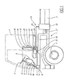
- Fig. 1 shows a vehicle 1.
- the vehicle 1 is constructed on a load-bearing frame 2, in which wheel axles 3 are suspended in a conventional way.
- the frame also supports a driver's cab 4.
- the vehicle shown consists of a heavy truck.
- the invention can be used on vehicles of all types but is most advantageous on heavy vehicles used in road transport, such as the tractor vehicle to a trailer.
- a steering wheel 5 is fitted in the driver's cab 4.
- the steering wheel 5 is supported in the usual manner by a steering column 6, which is securely mounted in the vehicle by means of a bracket 7.
- the invention can also be used on vehicles in which steering is performed electronically, the lock applied to the steering wheel being registered by a sensor which then undertakes control of the vehicle by way of actuators controlled by the sensor. In such a case the steering wheel may be supported in a weaker structure than steering columns commonly encountered at present.
- a shock-absorbing occupant protection 8 is fitted behind the steering column 6 in the vehicle direction of travel.
- the shock-absorbing device 8 comprises a container 9 of flexible design which is gas-filled in an original expanded rest position.
- the parts of the container 9 that are visible from the inside of the cab, which corresponds to an impact surface for the container, are preferably covered by a panel material 10 selected for the cab.
- the panel material 10 together with the wall 11 of the container are preferably designed to distribute the force over the surface of the container.
- the panel material or the parts of the container wall bearing against the impact surface may be made from a relatively rigid plastic or composite material.
- the container 9 has at least one flexible wall 12, which is designed to be deformed on impact so that the container is compressed. In a preferred embodiment the volume of the container is reduced under deformation so that the pressure in the container increases.
- the flexible wall 12 may be made substantially thinner than the wall of the container on the impact surface.
- the shock-absorbing device 8 has means 13 of returning the container to said original expanded rest position following compression of the container.
- these means 13 comprise a pressurized tank 14, which by way of an air inlet valve 15 is designed to deliver a working pressure of the flexible container 9.
- the container 9 furthermore has one or more outlet valves 16. Should an occupant be thrown against the flexible container 9, this will be compressed increasing the pressure. In this state the outlet valves open and gas is discharged. Should the occupant cease to compress the container 9, the pressure in the container 9 falls drastically. The supply flow of gas through the air inlet valve 15 allows the container 9 to be re-pressurized, thereby enabling it to return to an original expanded position.
- the air inlet valve and/or the outlet valve are controlled by a control unit 17.
- the control unit 17 ensures that the working pressure and/or the outlet flow through the outlet valve 16 are adjusted according to the speed of the vehicle at the instant of collision and/or the weight of the occupant.
- a driver's seat 18 is fitted in the driver's cab 4.
- the backrest 19 of the driver's seat has a shock-absorbing device 20.
- This shock-absorbing device 20 also comprises a flexible container 21, which is connected to a pressurized tank 22 by way of an inlet valve 23. On compression of the container 21, the discharge of air is permitted through outlet valves 24.
- This shock-absorbing device is used in order to afford protection to a passenger traveling behind the seat 18, where appropriate in a recumbent position on a bunk 25.
- the pressurized tanks 14, 22 assigned to the shock-absorbing devices 8, 20 are fed from the vehicle compressed air system 26.
- This compressed air system comprises a compressor 27, which may be powered by the engine 28 of the vehicle or where appropriate it may consist of one or more of the cylinder chambers of the internal combustion engine, which under particular operating conditions is/are closed for normal operation and are instead used for supplying compressed air.
- the compressor 27 supplies one or more main tanks 30.
- a compressed air line 29 connects the main tank 30 to the pressurized tanks 14, 22 assigned to the shock-absorbing devices 8, 20.
- the main tank 30 may be coupled directly to the flexible container 9, 21.
- the pressurized tank 14, 22 is preferably connected to the flexible container 9, 21 by way of a pressure line 35, 36, the length of which is less than 0.8 m, preferably 0.4 m.
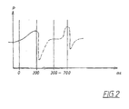
- Fig. 2 shows the pressure curve in a flexible container as a function of the time in a collision involving two impacts.
- time t 0 an occupant strikes a flexible container.
- the occupant compresses the flexible container for approximately 200 ms.
- the pressure rises as a result of the compression of the container.
- Supplying gas enables the container to completely or partially recover its original shape.
- the shock-absorbing device is preferably designed to be re-supplied with gas for a period of between 100 and 500 ms.
- the figure also shows a second impact, which occurs after the gas-filled container has been refilled.
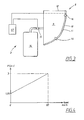
- Fig. 4 shows a diagram of the variation in working pressure as a function of the speed of the vehicle.
- the working pressure increases as a function of the speed.
- the working pressure increases linearly as a function of the speed.
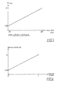
- Fig. 5 shows a diagram of the variation in working pressure in relation to the weight of the occupant.
- the working pressure increases as a function of the weight of the occupant.
- Fig. 6 shows a diagram of the permitted, normalized volumetric flow out through the outlet air valves as a function of the normalized mass of the occupant or the normalized speed of the vehicle.
- the speed is preferably normalized for speeds of between 0 and 80 km/h and the mass of the occupant between 20 kg and 120 kg.
- the flow is normalized for a given speed, a variation of the discharge volumetric flow then being permitted around the normalized figure.
Landscapes
- Engineering & Computer Science (AREA)
- Mechanical Engineering (AREA)
- Aviation & Aerospace Engineering (AREA)
- Transportation (AREA)
- Air Bags (AREA)
- Vibration Dampers (AREA)
- Lock And Its Accessories (AREA)
- Treatment And Processing Of Natural Fur Or Leather (AREA)
- Emergency Lowering Means (AREA)
- Refuge Islands, Traffic Blockers, Or Guard Fence (AREA)
Claims (8)
- Stoßabsorbierender Insassenschutz (8) für die Fahrgastzelle eines Fahrzeugs (1), der einen Behälter (9) mit flexibler Gestaltung umfasst, der in einer ursprünglichen ausgedehnten Ruheposition mit Gas gefüllt und dafür bestimmt ist, zusammengedrückt zu werden, wenn beim Aufprall eines Fahrzeuginsassen Energie absorbiert wird, wobei der Insassenschutz (8) eine Einrichtung (13) umfasst, die den Behälter (9) nach Zusammendrücken des Behälters in die ursprüngliche ausgedehnte Ruheposition zurückführt, dadurch gekennzeichnet, dass der Insassenschutz eine Steuereinheit (17) umfasst, die dazu bestimmt ist, über ein Lufteinlassventil (15) einen Arbeitsdruck für den flexiblen Behälter (9) als eine Funktion der Menge an Energie zu regulieren, die der Behälter (9) absorbieren muss.
- Stoßabsorbierender Insassenschutz nach Anspruch 1, dadurch gekennzeichnet, dass die Einrichtung (13), die den Behälter in die ursprüngliche ausgedehnte Ruheposition zurückführt, einen unter Druck stehenden Tank (14) umfasst, der mit dem flexiblen Behälter (9) über das Lufteinlassventil (15) verbunden ist und den Arbeitsdruck für den flexiblen Behälter (9) zuführt.
- Stoßabsorbierender Insassenschutz nach Anspruch 2, dadurch gekennzeichnet, dass der flexible Behälter (9) mit wenigstens einem Auslassventil (16) versehen ist, das dazu bestimmt ist, sich bei einem höheren Druck als dem Arbeitsdruck für den Behälter (9) zu öffnen.
- Stoßabsorbierender Insassenschutz nach Anspruch 1, dadurch gekennzeichnet, dass die Steuereinheit (17) dazu bestimmt ist, den Arbeitsdruck als eine Funktion der Geschwindigkeit des Fahrzeugs zu regulieren.
- Stoßabsorbierender Insassenschutz nach Anspruch 1 oder 4, dadurch gekennzeichnet, dass die Steuereinheit (17) dazu bestimmt ist, den Arbeitsdruck als eine Funktion des vorgesehenen Gewichtes des Benutzers zu regulieren.
- Stoßabsorbierender Insassenschutz nach einem der vorangehenden Ansprüche, dadurch gekennzeichnet, dass die Steuereinheit (17) dazu bestimmt ist, den Druck, bei dem sich das Auslassventil (16) öffnet, als eine Funktion der Geschwindigkeit des Fahrzeugs und/oder des Gewichtes des Insassen zu regulieren.
- Stoßabsorbierender Insassenschutz nach einem der vorangehenden Ansprüche, dadurch gekennzeichnet, dass der Arbeitsdruck zwischen 1,05 und 3 bar, vorzugsweise zwischen 1,6 und 2 bar über atmosphärischem Druck liegt.
- Fahrzeug (1), das ein Druckluft-Zufuhrsystem (26) und einen stoßabsorbierenden Insassenschutz (8) nach einem der Ansprüche 2 oder 7 umfasst, dadurch gekennzeichnet, dass der unter Druck stehende Tank (14) mit dem Druckluft-Zufuhrsystem (26) des Fahrzeugs verbunden ist.
Applications Claiming Priority (3)
| Application Number | Priority Date | Filing Date | Title |
|---|---|---|---|
| SE0203800A SE524431C2 (sv) | 2002-12-20 | 2002-12-20 | Stötdämpande kollisionsskydd |
| SE0203800 | 2002-12-20 | ||
| PCT/SE2003/001948 WO2004056617A1 (en) | 2002-12-20 | 2003-12-15 | Shock-absorbing occupant protection |
Publications (2)
| Publication Number | Publication Date |
|---|---|
| EP1575809A1 EP1575809A1 (de) | 2005-09-21 |
| EP1575809B1 true EP1575809B1 (de) | 2007-09-12 |
Family
ID=20289950
Family Applications (1)
| Application Number | Title | Priority Date | Filing Date |
|---|---|---|---|
| EP03768452A Expired - Lifetime EP1575809B1 (de) | 2002-12-20 | 2003-12-15 | Stossdämpfender schutz für insassen |
Country Status (8)
| Country | Link |
|---|---|
| US (1) | US7500695B2 (de) |
| EP (1) | EP1575809B1 (de) |
| JP (1) | JP4570961B2 (de) |
| AT (1) | ATE372901T1 (de) |
| AU (1) | AU2003292914A1 (de) |
| DE (1) | DE60316343T2 (de) |
| SE (1) | SE524431C2 (de) |
| WO (1) | WO2004056617A1 (de) |
Families Citing this family (3)
| Publication number | Priority date | Publication date | Assignee | Title |
|---|---|---|---|---|
| WO2013169147A1 (en) * | 2012-05-08 | 2013-11-14 | Volvo Lastvagnar Ab | A vehicle with a suspended driver unit with locking and force absorbing means |
| FR3026067B1 (fr) * | 2014-09-24 | 2018-01-26 | Psa Automobiles Sa. | Dispositif anti sous-marinage comprenant un reservoir |
| CN105946761B (zh) * | 2016-07-11 | 2018-08-31 | 潍柴动力股份有限公司 | 车辆的正面碰撞防护装置 |
Family Cites Families (16)
| Publication number | Priority date | Publication date | Assignee | Title |
|---|---|---|---|---|
| DE836748C (de) * | 1950-10-27 | 1952-04-17 | Franz Derwahl | Sicherheitsanordnung fuer Insassen in Fahrzeugen, insbesondere in Personenkraftfahrzeugen |
| US3130807A (en) * | 1962-07-05 | 1964-04-28 | Bobby R Mchenry | Air cushion dashboard for automobiles and the like |
| US3370886A (en) * | 1966-03-04 | 1968-02-27 | Frost James Dahle | Energy absorbing cushion |
| US3603535A (en) * | 1968-11-13 | 1971-09-07 | Maurice Depolo | Lifesaving support system |
| US3614129A (en) * | 1969-09-29 | 1971-10-19 | Ford Motor Co | Vehicle passenger restraint arrangement including a compartmentalized air bag |
| US3650223A (en) * | 1970-09-04 | 1972-03-21 | Techikawa Spring Co Ltd | Air bag table |
| US5141279A (en) * | 1991-09-23 | 1992-08-25 | Davidson Textron Inc. | Side impact protection apparatus |
| US5427331A (en) * | 1994-04-01 | 1995-06-27 | Lockheed Corporation | Rapid deflation system for pneumatic seat cushion |
| DE4441777C2 (de) | 1994-11-24 | 2002-11-28 | Holm Singer | Verfahren zur Aufprallenergie-Absorption und Raumvergrößerung für Fahrzeuge (CIS) und Einrichtung dafür |
| DE19647690C1 (de) * | 1996-11-05 | 1998-04-02 | Lignotock Gmbh | Innenverkleidungsteil für Kraftfahrzeuge |
| US5967594A (en) * | 1998-05-26 | 1999-10-19 | Ford Global Technologies, Inc. | Vehicle door structure and armrest |
| US5902010A (en) * | 1998-06-22 | 1999-05-11 | Trw Inc. | Vehicle occupant restraint apparatus |
| DE19927403C2 (de) * | 1999-06-16 | 2003-02-13 | Daimler Chrysler Ag | Rückenlehne für einen Fahrzeugsitz |
| US6203105B1 (en) * | 1999-08-20 | 2001-03-20 | Mccord Winn Textron Inc. | Vehicle impact responsive multiple bladder seating and headrest system and method |
| JP4273604B2 (ja) * | 2000-01-21 | 2009-06-03 | トヨタ自動車株式会社 | 車輌の乗員保護装置 |
| DE10036261A1 (de) * | 2000-07-26 | 2002-02-07 | Daimler Chrysler Ag | Kopfstütze |
-
2002
- 2002-12-20 SE SE0203800A patent/SE524431C2/sv not_active IP Right Cessation
-
2003
- 2003-12-15 EP EP03768452A patent/EP1575809B1/de not_active Expired - Lifetime
- 2003-12-15 DE DE60316343T patent/DE60316343T2/de not_active Expired - Lifetime
- 2003-12-15 AT AT03768452T patent/ATE372901T1/de not_active IP Right Cessation
- 2003-12-15 WO PCT/SE2003/001948 patent/WO2004056617A1/en not_active Ceased
- 2003-12-15 JP JP2004562185A patent/JP4570961B2/ja not_active Expired - Fee Related
- 2003-12-15 AU AU2003292914A patent/AU2003292914A1/en not_active Abandoned
-
2005
- 2005-06-20 US US11/160,346 patent/US7500695B2/en not_active Expired - Fee Related
Also Published As
| Publication number | Publication date |
|---|---|
| SE0203800L (sv) | 2004-06-21 |
| US7500695B2 (en) | 2009-03-10 |
| JP4570961B2 (ja) | 2010-10-27 |
| DE60316343D1 (de) | 2007-10-25 |
| JP2006510536A (ja) | 2006-03-30 |
| EP1575809A1 (de) | 2005-09-21 |
| US20050230951A1 (en) | 2005-10-20 |
| ATE372901T1 (de) | 2007-09-15 |
| SE0203800D0 (sv) | 2002-12-20 |
| WO2004056617A1 (en) | 2004-07-08 |
| DE60316343T2 (de) | 2008-06-12 |
| AU2003292914A1 (en) | 2004-07-14 |
| SE524431C2 (sv) | 2004-08-10 |
Similar Documents
| Publication | Publication Date | Title |
|---|---|---|
| US4176858A (en) | Energy absorbing bumper system | |
| US8346438B2 (en) | Rear impact detection method and system | |
| US7744122B2 (en) | Driver side aspirated airbags | |
| CN101665102B (zh) | 车辆的外部安全气囊 | |
| US5904370A (en) | Lining element for vehicles | |
| US8376451B2 (en) | Automotive collision energy dissipation device | |
| US3810668A (en) | Energy absorbing bumper system | |
| EP0757634B1 (de) | Fahrzeugunterbau mit fahrgastraum | |
| CN106114431A (zh) | 一种汽车落水防护装置 | |
| US3810653A (en) | Motor vehicles equipped with gas cushion | |
| US9061653B2 (en) | Method and device for controlling the filling of an airbag for a vehicle and an airbag system | |
| US20060138763A1 (en) | Airbag and sensor-equipped roll bar for open vehicles | |
| EP1575809B1 (de) | Stossdämpfender schutz für insassen | |
| US6502856B1 (en) | Rollover air bag system | |
| US10710543B2 (en) | Central passenger air bag | |
| US11827170B2 (en) | Gas-fillable support means for a motor vehicle and motor vehicle equipped therewith | |
| GB2299306A (en) | Inflatable airbag for a vehicle | |
| EP0784548B1 (de) | Einrichtung und verfahren zum füllen eines luftsackes | |
| Sabarinath | Passive Safety System for Side Impact in Cars | |
| CN206374708U (zh) | 一种汽车 | |
| RU39309U1 (ru) | Охранная система для предотвращения несанкционированного использования транспортного средства | |
| KR20010103853A (ko) | 자동차의 승객보호용 에어쿠션 | |
| KR0181845B1 (ko) | 에어백의 탑승자 보호 장치 | |
| GB2354980A (en) | Vehicle with an inflatable device in front of the engine | |
| KR19980052287A (ko) | 후방충격 흡수용 에어 백 구조 |
Legal Events
| Date | Code | Title | Description |
|---|---|---|---|
| PUAI | Public reference made under article 153(3) epc to a published international application that has entered the european phase |
Free format text: ORIGINAL CODE: 0009012 |
|
| 17P | Request for examination filed |
Effective date: 20050713 |
|
| AK | Designated contracting states |
Kind code of ref document: A1 Designated state(s): AT BE BG CH CY CZ DE DK EE ES FI FR GB GR HU IE IT LI LU MC NL PT RO SE SI SK TR |
|
| AX | Request for extension of the european patent |
Extension state: AL LT LV MK |
|
| DAX | Request for extension of the european patent (deleted) | ||
| GRAP | Despatch of communication of intention to grant a patent |
Free format text: ORIGINAL CODE: EPIDOSNIGR1 |
|
| GRAS | Grant fee paid |
Free format text: ORIGINAL CODE: EPIDOSNIGR3 |
|
| GRAA | (expected) grant |
Free format text: ORIGINAL CODE: 0009210 |
|
| AK | Designated contracting states |
Kind code of ref document: B1 Designated state(s): AT BE BG CH CY CZ DE DK EE ES FI FR GB GR HU IE IT LI LU MC NL PT RO SE SI SK TR |
|
| REG | Reference to a national code |
Ref country code: GB Ref legal event code: FG4D |
|
| REG | Reference to a national code |
Ref country code: CH Ref legal event code: EP |
|
| REF | Corresponds to: |
Ref document number: 60316343 Country of ref document: DE Date of ref document: 20071025 Kind code of ref document: P |
|
| REG | Reference to a national code |
Ref country code: IE Ref legal event code: FG4D |
|
| REG | Reference to a national code |
Ref country code: SE Ref legal event code: TRGR |
|
| PG25 | Lapsed in a contracting state [announced via postgrant information from national office to epo] |
Ref country code: FI Free format text: LAPSE BECAUSE OF FAILURE TO SUBMIT A TRANSLATION OF THE DESCRIPTION OR TO PAY THE FEE WITHIN THE PRESCRIBED TIME-LIMIT Effective date: 20070912 |
|
| PG25 | Lapsed in a contracting state [announced via postgrant information from national office to epo] |
Ref country code: CH Free format text: LAPSE BECAUSE OF FAILURE TO SUBMIT A TRANSLATION OF THE DESCRIPTION OR TO PAY THE FEE WITHIN THE PRESCRIBED TIME-LIMIT Effective date: 20070912 Ref country code: LI Free format text: LAPSE BECAUSE OF FAILURE TO SUBMIT A TRANSLATION OF THE DESCRIPTION OR TO PAY THE FEE WITHIN THE PRESCRIBED TIME-LIMIT Effective date: 20070912 Ref country code: AT Free format text: LAPSE BECAUSE OF FAILURE TO SUBMIT A TRANSLATION OF THE DESCRIPTION OR TO PAY THE FEE WITHIN THE PRESCRIBED TIME-LIMIT Effective date: 20070912 |
|
| NLV1 | Nl: lapsed or annulled due to failure to fulfill the requirements of art. 29p and 29m of the patents act | ||
| PG25 | Lapsed in a contracting state [announced via postgrant information from national office to epo] |
Ref country code: BE Free format text: LAPSE BECAUSE OF FAILURE TO SUBMIT A TRANSLATION OF THE DESCRIPTION OR TO PAY THE FEE WITHIN THE PRESCRIBED TIME-LIMIT Effective date: 20070912 |
|
| REG | Reference to a national code |
Ref country code: CH Ref legal event code: PL |
|
| PG25 | Lapsed in a contracting state [announced via postgrant information from national office to epo] |
Ref country code: ES Free format text: LAPSE BECAUSE OF FAILURE TO SUBMIT A TRANSLATION OF THE DESCRIPTION OR TO PAY THE FEE WITHIN THE PRESCRIBED TIME-LIMIT Effective date: 20071223 Ref country code: NL Free format text: LAPSE BECAUSE OF FAILURE TO SUBMIT A TRANSLATION OF THE DESCRIPTION OR TO PAY THE FEE WITHIN THE PRESCRIBED TIME-LIMIT Effective date: 20070912 Ref country code: GR Free format text: LAPSE BECAUSE OF FAILURE TO SUBMIT A TRANSLATION OF THE DESCRIPTION OR TO PAY THE FEE WITHIN THE PRESCRIBED TIME-LIMIT Effective date: 20071213 |
|
| ET | Fr: translation filed | ||
| PG25 | Lapsed in a contracting state [announced via postgrant information from national office to epo] |
Ref country code: PT Free format text: LAPSE BECAUSE OF FAILURE TO SUBMIT A TRANSLATION OF THE DESCRIPTION OR TO PAY THE FEE WITHIN THE PRESCRIBED TIME-LIMIT Effective date: 20080212 Ref country code: CZ Free format text: LAPSE BECAUSE OF FAILURE TO SUBMIT A TRANSLATION OF THE DESCRIPTION OR TO PAY THE FEE WITHIN THE PRESCRIBED TIME-LIMIT Effective date: 20070912 Ref country code: SK Free format text: LAPSE BECAUSE OF FAILURE TO SUBMIT A TRANSLATION OF THE DESCRIPTION OR TO PAY THE FEE WITHIN THE PRESCRIBED TIME-LIMIT Effective date: 20070912 |
|
| PG25 | Lapsed in a contracting state [announced via postgrant information from national office to epo] |
Ref country code: RO Free format text: LAPSE BECAUSE OF FAILURE TO SUBMIT A TRANSLATION OF THE DESCRIPTION OR TO PAY THE FEE WITHIN THE PRESCRIBED TIME-LIMIT Effective date: 20070912 |
|
| PLBE | No opposition filed within time limit |
Free format text: ORIGINAL CODE: 0009261 |
|
| STAA | Information on the status of an ep patent application or granted ep patent |
Free format text: STATUS: NO OPPOSITION FILED WITHIN TIME LIMIT |
|
| PG25 | Lapsed in a contracting state [announced via postgrant information from national office to epo] |
Ref country code: MC Free format text: LAPSE BECAUSE OF NON-PAYMENT OF DUE FEES Effective date: 20071231 Ref country code: DK Free format text: LAPSE BECAUSE OF FAILURE TO SUBMIT A TRANSLATION OF THE DESCRIPTION OR TO PAY THE FEE WITHIN THE PRESCRIBED TIME-LIMIT Effective date: 20070912 |
|
| 26N | No opposition filed |
Effective date: 20080613 |
|
| PG25 | Lapsed in a contracting state [announced via postgrant information from national office to epo] |
Ref country code: IE Free format text: LAPSE BECAUSE OF NON-PAYMENT OF DUE FEES Effective date: 20071217 |
|
| PG25 | Lapsed in a contracting state [announced via postgrant information from national office to epo] |
Ref country code: EE Free format text: LAPSE BECAUSE OF FAILURE TO SUBMIT A TRANSLATION OF THE DESCRIPTION OR TO PAY THE FEE WITHIN THE PRESCRIBED TIME-LIMIT Effective date: 20070912 |
|
| PG25 | Lapsed in a contracting state [announced via postgrant information from national office to epo] |
Ref country code: SI Free format text: LAPSE BECAUSE OF FAILURE TO SUBMIT A TRANSLATION OF THE DESCRIPTION OR TO PAY THE FEE WITHIN THE PRESCRIBED TIME-LIMIT Effective date: 20070912 |
|
| PG25 | Lapsed in a contracting state [announced via postgrant information from national office to epo] |
Ref country code: CY Free format text: LAPSE BECAUSE OF FAILURE TO SUBMIT A TRANSLATION OF THE DESCRIPTION OR TO PAY THE FEE WITHIN THE PRESCRIBED TIME-LIMIT Effective date: 20070912 |
|
| PG25 | Lapsed in a contracting state [announced via postgrant information from national office to epo] |
Ref country code: LU Free format text: LAPSE BECAUSE OF NON-PAYMENT OF DUE FEES Effective date: 20071215 Ref country code: BG Free format text: LAPSE BECAUSE OF FAILURE TO SUBMIT A TRANSLATION OF THE DESCRIPTION OR TO PAY THE FEE WITHIN THE PRESCRIBED TIME-LIMIT Effective date: 20071212 |
|
| PG25 | Lapsed in a contracting state [announced via postgrant information from national office to epo] |
Ref country code: TR Free format text: LAPSE BECAUSE OF FAILURE TO SUBMIT A TRANSLATION OF THE DESCRIPTION OR TO PAY THE FEE WITHIN THE PRESCRIBED TIME-LIMIT Effective date: 20070912 Ref country code: HU Free format text: LAPSE BECAUSE OF FAILURE TO SUBMIT A TRANSLATION OF THE DESCRIPTION OR TO PAY THE FEE WITHIN THE PRESCRIBED TIME-LIMIT Effective date: 20080313 |
|
| PG25 | Lapsed in a contracting state [announced via postgrant information from national office to epo] |
Ref country code: FR Free format text: LAPSE BECAUSE OF NON-PAYMENT OF DUE FEES Effective date: 20091231 |
|
| PGFP | Annual fee paid to national office [announced via postgrant information from national office to epo] |
Ref country code: FR Payment date: 20101224 Year of fee payment: 8 |
|
| PG25 | Lapsed in a contracting state [announced via postgrant information from national office to epo] |
Ref country code: IT Free format text: LAPSE BECAUSE OF NON-PAYMENT OF DUE FEES Effective date: 20071231 |
|
| PGFP | Annual fee paid to national office [announced via postgrant information from national office to epo] |
Ref country code: SE Payment date: 20101213 Year of fee payment: 8 Ref country code: GB Payment date: 20101215 Year of fee payment: 8 |
|
| PGFP | Annual fee paid to national office [announced via postgrant information from national office to epo] |
Ref country code: DE Payment date: 20101208 Year of fee payment: 8 |
|
| REG | Reference to a national code |
Ref country code: SE Ref legal event code: EUG |
|
| GBPC | Gb: european patent ceased through non-payment of renewal fee |
Effective date: 20111215 |
|
| REG | Reference to a national code |
Ref country code: FR Ref legal event code: ST Effective date: 20120831 |
|
| REG | Reference to a national code |
Ref country code: DE Ref legal event code: R119 Ref document number: 60316343 Country of ref document: DE Effective date: 20120703 |
|
| PG25 | Lapsed in a contracting state [announced via postgrant information from national office to epo] |
Ref country code: GB Free format text: LAPSE BECAUSE OF NON-PAYMENT OF DUE FEES Effective date: 20111215 Ref country code: SE Free format text: LAPSE BECAUSE OF NON-PAYMENT OF DUE FEES Effective date: 20111216 Ref country code: DE Free format text: LAPSE BECAUSE OF NON-PAYMENT OF DUE FEES Effective date: 20120703 |
|
| PG25 | Lapsed in a contracting state [announced via postgrant information from national office to epo] |
Ref country code: FR Free format text: LAPSE BECAUSE OF NON-PAYMENT OF DUE FEES Effective date: 20120102 |