EP1575309A1 - Optischer Aufnahme/Wiedergabe- Apparat, mit einer Funktion zum Trennen der Helligkeits- und Farbbestandteile - Google Patents
Optischer Aufnahme/Wiedergabe- Apparat, mit einer Funktion zum Trennen der Helligkeits- und Farbbestandteile Download PDFInfo
- Publication number
- EP1575309A1 EP1575309A1 EP05250668A EP05250668A EP1575309A1 EP 1575309 A1 EP1575309 A1 EP 1575309A1 EP 05250668 A EP05250668 A EP 05250668A EP 05250668 A EP05250668 A EP 05250668A EP 1575309 A1 EP1575309 A1 EP 1575309A1
- Authority
- EP
- European Patent Office
- Prior art keywords
- video signal
- digital video
- color components
- luminance
- operable
- Prior art date
- Legal status (The legal status is an assumption and is not a legal conclusion. Google has not performed a legal analysis and makes no representation as to the accuracy of the status listed.)
- Ceased
Links
Images



Classifications
-
- G—PHYSICS
- G11—INFORMATION STORAGE
- G11B—INFORMATION STORAGE BASED ON RELATIVE MOVEMENT BETWEEN RECORD CARRIER AND TRANSDUCER
- G11B20/00—Signal processing not specific to the method of recording or reproducing; Circuits therefor
- G11B20/10—Digital recording or reproducing
-
- H—ELECTRICITY
- H04—ELECTRIC COMMUNICATION TECHNIQUE
- H04N—PICTORIAL COMMUNICATION, e.g. TELEVISION
- H04N9/00—Details of colour television systems
- H04N9/77—Circuits for processing the brightness signal and the chrominance signal relative to each other, e.g. adjusting the phase of the brightness signal relative to the colour signal, correcting differential gain or differential phase
- H04N9/78—Circuits for processing the brightness signal and the chrominance signal relative to each other, e.g. adjusting the phase of the brightness signal relative to the colour signal, correcting differential gain or differential phase for separating the brightness signal or the chrominance signal from the colour television signal, e.g. using comb filter
-
- H—ELECTRICITY
- H04—ELECTRIC COMMUNICATION TECHNIQUE
- H04N—PICTORIAL COMMUNICATION, e.g. TELEVISION
- H04N9/00—Details of colour television systems
- H04N9/79—Processing of colour television signals in connection with recording
- H04N9/80—Transformation of the television signal for recording, e.g. modulation, frequency changing; Inverse transformation for playback
- H04N9/804—Transformation of the television signal for recording, e.g. modulation, frequency changing; Inverse transformation for playback involving pulse code modulation of the colour picture signal components
- H04N9/8042—Transformation of the television signal for recording, e.g. modulation, frequency changing; Inverse transformation for playback involving pulse code modulation of the colour picture signal components involving data reduction
-
- G—PHYSICS
- G11—INFORMATION STORAGE
- G11B—INFORMATION STORAGE BASED ON RELATIVE MOVEMENT BETWEEN RECORD CARRIER AND TRANSDUCER
- G11B20/00—Signal processing not specific to the method of recording or reproducing; Circuits therefor
- G11B20/10—Digital recording or reproducing
- G11B20/10527—Audio or video recording; Data buffering arrangements
- G11B2020/10537—Audio or video recording
-
- H—ELECTRICITY
- H04—ELECTRIC COMMUNICATION TECHNIQUE
- H04N—PICTORIAL COMMUNICATION, e.g. TELEVISION
- H04N5/00—Details of television systems
- H04N5/76—Television signal recording
- H04N5/78—Television signal recording using magnetic recording
- H04N5/781—Television signal recording using magnetic recording on disks or drums
-
- H—ELECTRICITY
- H04—ELECTRIC COMMUNICATION TECHNIQUE
- H04N—PICTORIAL COMMUNICATION, e.g. TELEVISION
- H04N5/00—Details of television systems
- H04N5/76—Television signal recording
- H04N5/84—Television signal recording using optical recording
- H04N5/85—Television signal recording using optical recording on discs or drums
Definitions
- the present invention relates to an optical recording/reproducing apparatus having a function of separating luminance and color components of a video signal. More particularly, but not exclusively, the present invention relates to an optical recording/reproducing apparatus having an audio/video (AN) codec, rather than a video decoder which separates the luminance and color components of a video signal.
- AN audio/video
- a conventional optical recording/reproducing apparatus inputs an analog signal, converts the analog signal into a digital signal, compresses the digital signal in a certain compression format to record the compressed digital signal in a recording medium, decompresses the stored digital signal, and reproduces the decompressed digital signal into an analog signal.
- optical recording media as recording media being currently used are classified into read-only recording media such as compact disc (CD)-read only memories (ROMs) and digital versatile disc (DVD)-ROMs, write-once recordable media such as CD ⁇ recordables (CD-Rs) and DVD ⁇ RS, and re-writable recording media such as DVD ⁇ rewritables (RWs) and DVD-random access memories (RAMs).
- read-only recording media such as compact disc (CD)-read only memories (ROMs) and digital versatile disc (DVD)-ROMs
- write-once recordable media such as CD ⁇ recordables (CD-Rs) and DVD ⁇ RS
- re-writable recording media such as DVD ⁇ rewritables (RWs) and DVD-random access memories (RAMs).
- the above recording media randomly access data recorded on a hard disc drive (HDD), record video and audio data of high quality, and quickly and conveniently record data compared to the recording on conventional video tapes.
- HDD hard disc drive
- the disk type recording media are being used more for recording and/or reproduction.
- FIG. 1 is a block diagram of an exemplary conventional optical recording/reproducing apparatus.
- the conventional optical recording/reproducing apparatus comprises a video decoder 110, a decoder memory 111, an audio analog-to-digital converter (A/D converter) 115, an A/V codec 130, a memory 140, a flash memory 145, a system controller 150, a video encoder 170, and an audio digital-to-analog converter (D/A converter) 180.
- the A/V codec 130 comprises an encoder 133 and a decoder 136 formed as a unit.
- Analog video and audio signals are input from diverse signal sources such as a broadcast reception antenna, a computer, and a settop box.
- the optical recording/reproducing apparatus processes the signals into video and audio signals for outputs, and the video and audio signals are displayed through an image display unit such as a cathode ray tube (CRT) or a liquid crystal display (LCD) and output through a sound output unit such as a speaker, respectively.
- an image display unit such as a cathode ray tube (CRT) or a liquid crystal display (LCD)
- LCD liquid crystal display
- the video decoder 110 converts an analog video signal into an input digital video signal. Further, the video decoder 110 separates luminance and color components from the digital video signal.
- the decoder memory 111 is used for separating the luminance and color components.
- the audio A/D converter 115 converts an analog audio signal into a digital audio signal.
- the analog video and audio signals may be provided from one of the plurality of diverse sources.
- the encoder 133 encodes the input digital signal in an established compression format, and mixes encoded data to generate a data stream.
- the encoder 130 encodes the input digital video signal in a moving picture experts group (MPEG)-2 (Video) format referred to as ISO/IEC 13818-3, and encodes a digital audio signal in a Dolby AC-3 digital standard.
- MPEG moving picture experts group
- the MPEG data stream output from the encoder 133 is recorded on a recording medium or on a hard disc drive (HDD).
- the decoder 136 decodes data applied from either the recording medium or the HDD. That is, the decoder 136 decodes by decompressing a signal compressed in a certain compression format for an output.
- the signal decoded by the decoder 136 is output to the video encoder 170 and an audio D/A converter 180.
- the video encoder 170 encodes the digital video data of the decoder 136 for an analog video output.
- the audio D/A converter 180 converts the digital audio signal of the decoder 136 into an analog audio signal for an analog audio output.
- the flash memory 145 stores an operating system and various application programs for operating the optical recording/reproducing apparatus.
- the system controller 150 controls overall operations of the optical recording/reproducing apparatus based on a user's input signal applied through a key or a remote controller.
- the conventional optical recording/reproducing apparatus comprises the video decoder 110 built with functions for separating luminance and color components of the analog input video signal.
- the conventional optical recording/reproducing apparatus has a problem that additional circuitry is required to carry out such functions. Therefore, a size of the video decoder and a production cost due to the additional circuitry are unnecessarily increased.
- the conventional optical recording/reproducing apparatus requires a dedicated decoder memory 111 in order to carry out functions for the video decoder to separate the luminance and color components.
- Embodiments of the present invention aim to solve the above and/or other problems associated with the conventional arrangement.
- An aim of embodiments of the present invention is to provide an optical recording/reproducing apparatus having an A/V codec or an encoder, rather than a video decoder, to carry out functions of separating luminance and color components.
- Another aim of embodiments of the present invention is to provide an optical recording/reproducing apparatus comprising a video decoder which does not require a memory and an additional circuit for separating the luminance and color components.
- an optical recording/reproducing apparatus for recording and reproducing data to and from an optical medium, comprising: a video decoder which is operable to convert an analog video signal into a converted digital video signal; an audio and video (A/V) codec comprising: a pre-compression processing unit which is operable to separate luminance and color components from the converted digital video signal, an encoder which is operable to compress the digital video signal having the separated luminance and color components in a predetermined compression format, and a decoder which is operable to decode to the compressed digital video signal; and a memory used for a storage space as the A/V codec separates, compresses and decodes the converted video signal.
- an audio and video (A/V) codec comprising: a pre-compression processing unit which is operable to separate luminance and color components from a digital video signal, an encoder which is operable to compress the digital video signal having the separated luminance and color components in a predetermined compression format, and a decoder which is operable to decode the compressed digital video signal.
- a method of operating an audio and video (A/V) codec comprising: comparing consecutive frames of an input digital video signal pixel by pixel, to separate luminance and color components from the input digital video signal; and compressing the digital video signal having the separated luminance and color components in a predetermined compression format, to store the compressed digital video signal.
- A/V audio and video
- the pre-compression processing unit preferably filters the converted digital video signal and separates the luminance and color components.
- the pre-compression processing unit compares pixel by pixel a predetermined number of consecutive frames of frames comprising the converted digital video signal, and separates the luminance (Y) and color (C) components.
- the pre-compression processing unit preferably comprises a 3-dimensional (3D) Y/C separator which compares, pixel by pixel, the predetermined number of consecutive frames among frames constructing the converted digital video signal, and separates the luminance and color components, and a time base corrector (TBC) which stabilizes synchronization of the digital video signal from which the luminance and color components are separated.
- 3D 3-dimensional
- TBC time base corrector
- the pre-compression processing unit preferably further comprises a noise attenuator which removes noise included in the synchronization-stabilized digital video signal.
- the pre-compression processing unit preferably bypasses the converted digital video signal to the encoder if the luminance and color components are separated from the converted signal.
- the video decoder preferably comprises a clamp module which clamps the analog video signal to a predetermined reference level, an automatic gain control module which controls a gain of the clamped analog video signal to a predetermined magnitude, and an A/D converter which converts the gain-controlled analog video signal into the digital signal.
- the analog video signal may be one of a radio frequency (RF) signal, a composite video banking sync (CVBS) signal, a super-video (S-video) signal, a Y/C signal, and a component signal.
- RF radio frequency
- CVBS composite video banking sync
- S-video super-video
- Y/C Y/C signal
- component signal a component signal.
- the predetermined compression format may be a moving picture experts group (MPEG) format.
- MPEG moving picture experts group
- FIG. 2 is a block diagram of an optical recording/reproducing apparatus 200 according to a first embodiment of the present invention.
- the optical recording/reproducing apparatus 200 comprises a video decoder 210, an A/V codec 230, and a memory 240.
- the A/V codec 230 comprises a pre-compression processing unit 220, an encoder 233, and a decoder 236.
- An analog video signal is input to the video decoder 210.
- the analog video signal may be input through a signal reception antenna and a cable, for example.
- the analog video signal may be one of a radio frequency (RF) signal with video and audio mixed, a composite video banking sync (CVBS) with color, luminance, and sync mixed as a video signal and provided along with an audio signal, an S-video (Y+C) signal in which luminance, sync and color are mixed, a component signal, and an RGB signal with red, green, blue, and the sync mixed.
- RF radio frequency
- CVBS composite video banking sync
- Y+C composite video banking sync
- RGB RGB signal with red, green, blue, and the sync mixed.
- FIG. 3 is a detailed block diagram of the video decoder 210 shown in FIG. 2.
- the video decoder 210 comprises a clamp module 212, an automatic gain control module 214, and an A/D converter 216.
- the clamp module 212 clamps the input analog video signal to a predetermined reference.
- the automatic gain control module 214 controls a gain of the clamped analog video signal to a predetermined magnitude.
- the A/D converter 216 converts the gain-controlled analog video signal into the digital video signal.
- FIG. 4 is a view illustrating the analog video signal.
- a portion 'a' of the video signal lies at the reference level Y 0
- a portion 'b' of the video signal is lower than the reference level Y 0
- a portion 'c' of the video signal is higher than the reference level Y 0 .
- the portions 'b' and 'c' are adjusted to the predetermined reference Y 0 by the clamp module 212. If an interval from Y 0 to Y L is referred to as 40IRE, S1 corresponds to 40IRE, however, S2 is smaller than 40IRE and S3 is larger than 40IRE.
- the automatic gain control module 214 adjusts S2 and S3 to 40IRE and T2 and T3 to 60IRE, controlling the gain to be constant.
- the A/V codec 230 compresses the input digital video signal in a predetermined format, or decompresses a compressed digital video signal of predetermined format. Description of the processing in the A/V codec 230 will be made below.
- a digital video signal is input from the video decoder 210 to the pre-compression processing unit 220.
- the input digital video signal has mixed luminance and color components.
- a signal with mixed luminance and color components is not appropriate to be compressed in the encoder 233, and therefore, the luminance and color components must be separated.
- the pre-compression processing unit 220 inputs a digital video signal with luminance and color components mixed, and outputs a digital video signal from which luminance and color components are separated.
- FIGS. 5A to 5C are views for showing an example of separating luminance and color components by filtering the digital video signal.
- FIG. 5A is a view for showing an example of a signal with luminance and color components mixed. If filter characteristics are the same as a dashed portion 500 of FIG. 5A, the luminance component Y after filtering may be separated as shown in FIG. 5B, and the color component C may be separated as shown in FIG. 5C. However, due to limits of the filtering characteristics, part of the color component is included in the luminance component, and part of the luminance component is included in the color component. In order to overcome such a problem, a method is used that compares a digital video signal pixel by pixel and separates luminance and color components.
- FIGS. 6A to 6B are views for showing an example of separating luminance and color components by comparing a digital video signal pixel by pixel.
- FIG. 6A shows two exemplary frames.
- a frame in computer graphics or television broadcast refers to an image produced through one scan on an entire screen in order to output information on a display unit, that is, an individual image of a moving picture continuously varying with time.
- Most computer monitors or television sets generate and display 30 or 60 frames per second. The number of frames per second is referred to as a frame frequency or frame transmission rate.
- the frame f n comprises pixels a 1 , a 2 , a 3 ,..., a n-2 , a n-1 , and a n
- the frame f n+1 comprises pixels b 1 , b 2 , b 3 ,..., b n-2 , b n-1 , and b n
- the luminance and color components are separated by comparing pixels a 1 and b 1 , a 2 and b 2 ,..., and a n and b n , respectively.
- the luminance variations and color variations may be used.
- the separation of the luminance and color components through comparing respective pixels is referred to as 3D separate, wherein the 3D implies comparison of different frames having time differences.
- the luminance and color components may separated by comparing respective pixels among 3 frames f n , f n+1 , and f n+2 .
- the video decoder 210 In order for the video decoder 210 to carry out the 3D separate, a separate memory is required to compare the frames. However, if the 3D separate is carried out in the A/V codec 230, the memory 240 used for the A/V codec 230 is shared. The memory 240 used for the encoder 233 and the decoder 236 may be shared by sharing the storage space of the memory 240. Therefore, the video decoder 210 does not need a dedicated decoder memory, and a size of the video decoder 210 and a production cost are reduced.
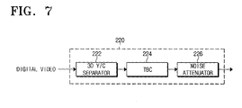
- FIG. 7 is a view showing the pre-compression processing unit 220 of FIG. 2 in detail.
- the pre-compression processing unit 220 has a 3D Y/C separator 222, a time base corrector (TBC) 224, and a noise attenuator 226.
- the 3D Y/C separator 222 is input with a digital video signal from the video decoder 210.
- the 3D Y/C separator 222 compares pixel by pixel a certain number of consecutive fields among the fields of a digital video signal, and then separates the luminance and color components.
- the 3D Y/C separator 222 uses the memory 240 in comparing the luminance and color components.
- the TBC 224 is input, from the 3D Y/C separator 222, with the digital video signal from which the luminance and color components are separated. If sync pulses become unstable with a non-standard signal input, screen defects may occur such as screen shivering, vertical screen variations and imbalance. For example, when a signal is input from a video tape recorder (VCR), the defects occur due to various errors resulting from tape and head traveling, defects of the tape itself and other various mechanical and electrical problems.
- VCR video tape recorder
- the TBC is a unit for compensating for the above defects by maintaining stable synchronization through a delay circuit and appropriate digital signal processing. Accordingly, the TBC stabilizes the synchronization of an input digital video signal.
- the noise attenuator 226 is input with a stably synchronized digital video signal from the TBC 224.
- the input digital video signal has noise generated during signal processing.
- the noise attenuator 226 removes noise other than video signal components.
- the arrangement of the TBC 224 and the noise attenuator 226 may be interchanged.
- the digital video signal input to the pre-compression processing unit 220 is a digital video signal from which luminance and color components are separated, the digital video signal may be bypassed to the encoder. If there is a need to stabilize synchronization or to remove noise, the digital video signal is outputted to the encoder 233 passing through the TBC 224 and the noise attenuator 226 at least.
- the encoder 233 is input, from the pre-compression processing unit 220, with a digital video signal from which luminance and color components are separated.
- the encoder 233 compresses the input signal in a predetermined compression format.
- the MPEG format may be used for the predetermined compression format; however, the compression format is not constrained to the MPEG format.
- the compressed signal is recorded on a recording medium (not shown) or an HDD (not shown).
- the decoder 236 decompresses a signal compressed and recorded in a predetermined compression format.
- the decompressed digital video signal is sent to a video encoder (not shown) from the decoder 236.
- the video encoder converts a digital video signal into an analog video signal.
- the converted analog video signal is displayed through an output unit (not shown).
- the analog video signal is denoted as Y/C, Y/Cr/Cb and Y/Pb/Pr, based on a format of the output unit.
- the memory 240 is used for a storage space when a signal is processed in the A/V codec 230. That is, the memory 240 is used as a storage space for the pre-compression processing unit 220 as well as for the encoder 233 and the decoder 236, when a signal is processed.
- the storage space used for the pre-compression processing unit 220 is smaller than that used for the encoder 233 and the decoder 236.
- the A/V codec 230 may be constructed in a single chip comprising the pre-compression processing unit 220, the encoder 233, and the decoder 236, or in individual single chips for the pre-compression processing unit 220, the encoder 233, and the decoder 236. Further, a description of audio signal processing in addition to the above will be omitted.
- FIG. 8 is a block diagram for showing an optical recording/reproducing apparatus 700 according to a second embodiment of the present invention.
- the optical recording/reproducing apparatus 700 comprises a video decoder 710, an A/V codec 730, and a memory 740.
- the video decoder 710 comprises a clamp module 712, an automatic gain control module 714, an A/D converter 716, and a filter module 718.
- the AN codec 730 comprises an encoder 733 and a decoder 736.
- a dedicated memory is not needed for the video decoder 710, however, the AN codec 730 does not carry out a function of separating luminance and color components. Only the filter module 718 will be described, excluding a repeated description.
- a digital video signal is input from the A/D converter 716 to the filter module 718.
- the filter module 718 filters the input digital video signal to separate luminance and color components.
- the digital video signal from which luminance and color components are separated is input to the encoder 733.
- the A/V codec rather than the video decoder, carries out the function of separating the luminance and color components. Therefore, the video decoder does not have to include additional circuits for separating the luminance and color components. As a result, the size of the video decoder and the production cost may be reduced.
- a dedicated memory is not necessary to carry out the function of separating the luminance and color components, and since the memory used for the A/V codec may be shared, the memory is efficiently used.
Landscapes
- Engineering & Computer Science (AREA)
- Signal Processing (AREA)
- Multimedia (AREA)
- Compression Or Coding Systems Of Tv Signals (AREA)
Applications Claiming Priority (2)
| Application Number | Priority Date | Filing Date | Title |
|---|---|---|---|
| KR2004015733 | 2004-03-09 | ||
| KR1020040015733A KR100545379B1 (ko) | 2004-03-09 | 2004-03-09 | 휘도/색차 성분 분리 기능이 내장된 광기록재생 장치 |
Publications (1)
| Publication Number | Publication Date |
|---|---|
| EP1575309A1 true EP1575309A1 (de) | 2005-09-14 |
Family
ID=34825183
Family Applications (1)
| Application Number | Title | Priority Date | Filing Date |
|---|---|---|---|
| EP05250668A Ceased EP1575309A1 (de) | 2004-03-09 | 2005-02-05 | Optischer Aufnahme/Wiedergabe- Apparat, mit einer Funktion zum Trennen der Helligkeits- und Farbbestandteile |
Country Status (4)
| Country | Link |
|---|---|
| US (1) | US7391962B2 (de) |
| EP (1) | EP1575309A1 (de) |
| KR (1) | KR100545379B1 (de) |
| CN (1) | CN1668098A (de) |
Families Citing this family (4)
| Publication number | Priority date | Publication date | Assignee | Title |
|---|---|---|---|---|
| KR100770706B1 (ko) * | 2006-02-08 | 2007-10-29 | 삼성전자주식회사 | 디스플레이 장치에서 입력 영상 신호의 새츄레이션 방지를위한 이득 조정 회로 및 이득 조정 방법 |
| JP4518043B2 (ja) * | 2006-05-31 | 2010-08-04 | 株式会社日立製作所 | 画像信号処理装置、及び画像信号を高解像度化するための方法、及びそれを実行するためのプログラム |
| CN100485722C (zh) * | 2006-12-30 | 2009-05-06 | 中国科学院计算技术研究所 | 一种色彩图像压缩码流的色彩分量实时分离方法及装置 |
| CN103813147A (zh) * | 2012-11-09 | 2014-05-21 | 浙江大华技术股份有限公司 | 一种视频信号的处理方法及装置 |
Citations (2)
| Publication number | Priority date | Publication date | Assignee | Title |
|---|---|---|---|---|
| US4970601A (en) * | 1987-03-06 | 1990-11-13 | Hitachi, Ltd. | Video signal processing apparatus for video tape recorder |
| US20010010748A1 (en) * | 2000-01-27 | 2001-08-02 | Matsushita Electric Industrial Co., Ltd. | Video signal processor for recording video signal digitally |
Family Cites Families (16)
| Publication number | Priority date | Publication date | Assignee | Title |
|---|---|---|---|---|
| GB1487573A (en) * | 1974-06-06 | 1977-10-05 | Quantel Ltd | Video time base corrector |
| JPH0640672B2 (ja) * | 1985-09-02 | 1994-05-25 | 株式会社日立製作所 | 磁気録画再生装置 |
| CA1286767C (en) * | 1987-05-29 | 1991-07-23 | Hajime Enomoto | Color picture image processing system for separating color picture imageinto pixels |
| US4785349A (en) * | 1987-10-05 | 1988-11-15 | Technology Inc. 64 | Digital video decompression system |
| US5036386A (en) * | 1988-07-22 | 1991-07-30 | Matsushita Electric Industrial Co., Ltd. | Television signal processing apparatus |
| US5095354A (en) * | 1989-09-01 | 1992-03-10 | Matsushita Electric Industrial Co., Ltd. | Scanning format converter with motion compensation |
| KR940005178B1 (ko) * | 1989-10-14 | 1994-06-11 | 미쯔비시 덴끼 가부시끼가이샤 | 움직임적응형 휘도신호 색신호 분리필터 및 그 분리방법 |
| US5526129A (en) * | 1990-11-19 | 1996-06-11 | Samsung Electronics Co., Ltd. | Time-base-correction in video recording using a frequency-modulated carrier |
| US5187568A (en) * | 1991-10-03 | 1993-02-16 | Zenith Electronics Corporation | Video processor having improved clamping system for color television receivers |
| US5374956A (en) * | 1992-05-29 | 1994-12-20 | Eastman Kodak Company | Electronic imaging apparatus with dithered color filter array |
| BR9405508A (pt) * | 1993-07-12 | 1999-09-08 | Sony Corp | Processo e aparelho decodificador e codificador de imagem. |
| US6088469A (en) * | 1996-09-30 | 2000-07-11 | Sony Corporation | Identifying apparatus and method, position detecting apparatus and method, robot apparatus and color extracting apparatus |
| ATE401647T1 (de) * | 2001-05-02 | 2008-08-15 | Pioneer Corp | Informationsaufzeichnungsmedium und informationsaufzeichnungsgerät |
| KR100750100B1 (ko) * | 2001-06-13 | 2007-08-17 | 삼성전자주식회사 | 아날로그/디지털 변환기를 구비한 영상처리장치 |
| CN2492976Y (zh) | 2001-09-07 | 2002-05-22 | 财团法人工业技术研究院 | 模拟信号的自动增益调整控制电路 |
| KR100449102B1 (ko) * | 2002-03-19 | 2004-09-18 | 삼성전자주식회사 | 멀티미디어용 시스템온칩 프로세서 |
-
2004
- 2004-03-09 KR KR1020040015733A patent/KR100545379B1/ko not_active Expired - Fee Related
- 2004-10-04 US US10/956,098 patent/US7391962B2/en not_active Expired - Fee Related
-
2005
- 2005-02-04 CN CNA2005100072072A patent/CN1668098A/zh active Pending
- 2005-02-05 EP EP05250668A patent/EP1575309A1/de not_active Ceased
Patent Citations (2)
| Publication number | Priority date | Publication date | Assignee | Title |
|---|---|---|---|---|
| US4970601A (en) * | 1987-03-06 | 1990-11-13 | Hitachi, Ltd. | Video signal processing apparatus for video tape recorder |
| US20010010748A1 (en) * | 2000-01-27 | 2001-08-02 | Matsushita Electric Industrial Co., Ltd. | Video signal processor for recording video signal digitally |
Non-Patent Citations (1)
| Title |
|---|
| ACKLAND B: "The role of VLSI in multimedia", ,, 19 May 1993 (1993-05-19), pages 1 - 4, XP010540485 * |
Also Published As
| Publication number | Publication date |
|---|---|
| US7391962B2 (en) | 2008-06-24 |
| KR100545379B1 (ko) | 2006-01-24 |
| KR20050090584A (ko) | 2005-09-14 |
| CN1668098A (zh) | 2005-09-14 |
| US20050201735A1 (en) | 2005-09-15 |
Similar Documents
| Publication | Publication Date | Title |
|---|---|---|
| US9402100B2 (en) | Integrated multimedia signal processing system using centralized processing of signals | |
| US7653447B2 (en) | Integrated audio video signal processing system using centralized processing of signals | |
| CN100452830C (zh) | 数字视讯处理装置及方法 | |
| JP4474748B2 (ja) | 信号処理装置及び方法、映像信号記録装置、並びに映像信号再生装置 | |
| US7391962B2 (en) | Optical recording/reproducing apparatus having a function of separating luminance and color components | |
| CN1088957C (zh) | 重放数字视盘的视频信号的装置及其方法 | |
| CN1538433A (zh) | 组合视频盘播放器和盒式录像机以及控制输出信号的方法 | |
| JP4341458B2 (ja) | 信号処理装置 | |
| JPH04271696A (ja) | 互換性を有する高解像度ビデオ記録方法及び装置 | |
| US7450831B2 (en) | Method for DVD-subpicture compositing in 420 chroma format | |
| JP2001326908A (ja) | 記録再生装置及び記録再生装置の制御方法 | |
| JP3075859B2 (ja) | 多重画面磁気記録再生装置 | |
| KR100617655B1 (ko) | 영상 및 자막 정보의 저장 및 재생을 위한 피브이알 시스템 | |
| JP2001285771A (ja) | ディスク可変速再生装置 | |
| JP3845473B2 (ja) | 映像信号記録装置 | |
| JP2000036939A (ja) | 画像記録装置 | |
| JP2001112012A (ja) | 撮像信号処理装置、撮像信号処理方法、データ復号装置、及び撮像装置 | |
| US20080219645A1 (en) | Reproducing Apparatus | |
| JP2001285891A (ja) | 信号変換装置 | |
| KR19990019812A (ko) | 광디스크 재생기기의 영상신호 출력장치 | |
| JPS63250296A (ja) | 映像信号記録/再生装置 | |
| JPH0998329A (ja) | カメラ装置及びカメラ一体型磁気記録再生装置 | |
| JPH06253256A (ja) | ビデオ信号出力装置、ビデオ信号記録装置およびビデオ信号記録媒体 | |
| JPH08275154A (ja) | 画像信号処理装置 |
Legal Events
| Date | Code | Title | Description |
|---|---|---|---|
| PUAI | Public reference made under article 153(3) epc to a published international application that has entered the european phase |
Free format text: ORIGINAL CODE: 0009012 |
|
| 17P | Request for examination filed |
Effective date: 20050219 |
|
| AK | Designated contracting states |
Kind code of ref document: A1 Designated state(s): AT BE BG CH CY CZ DE DK EE ES FI FR GB GR HU IE IS IT LI LT LU MC NL PL PT RO SE SI SK TR |
|
| AX | Request for extension of the european patent |
Extension state: AL BA HR LV MK YU |
|
| AKX | Designation fees paid |
Designated state(s): DE FR GB NL |
|
| STAA | Information on the status of an ep patent application or granted ep patent |
Free format text: STATUS: THE APPLICATION HAS BEEN REFUSED |
|
| 18R | Application refused |
Effective date: 20091207 |