EP1575186A1 - Verfahren und Gerät zur Sendeleistungssteuerung in einer Aufwärtsverbindung um die gewünschte Rahmenfehlerrateeinstellungen in einem drahtlosen Kommunikationssystem zu bewahren - Google Patents
Verfahren und Gerät zur Sendeleistungssteuerung in einer Aufwärtsverbindung um die gewünschte Rahmenfehlerrateeinstellungen in einem drahtlosen Kommunikationssystem zu bewahren Download PDFInfo
- Publication number
- EP1575186A1 EP1575186A1 EP05251293A EP05251293A EP1575186A1 EP 1575186 A1 EP1575186 A1 EP 1575186A1 EP 05251293 A EP05251293 A EP 05251293A EP 05251293 A EP05251293 A EP 05251293A EP 1575186 A1 EP1575186 A1 EP 1575186A1
- Authority
- EP
- European Patent Office
- Prior art keywords
- pilot
- frame
- signal
- pilot signal
- transmitted
- Prior art date
- Legal status (The legal status is an assumption and is not a legal conclusion. Google has not performed a legal analysis and makes no representation as to the accuracy of the status listed.)
- Granted
Links
Images


Classifications
-
- H—ELECTRICITY
- H04—ELECTRIC COMMUNICATION TECHNIQUE
- H04W—WIRELESS COMMUNICATION NETWORKS
- H04W52/00—Power management, e.g. TPC [Transmission Power Control], power saving or power classes
- H04W52/04—TPC
- H04W52/30—TPC using constraints in the total amount of available transmission power
- H04W52/32—TPC of broadcast or control channels
- H04W52/325—Power control of control or pilot channels
-
- H—ELECTRICITY
- H04—ELECTRIC COMMUNICATION TECHNIQUE
- H04W—WIRELESS COMMUNICATION NETWORKS
- H04W28/00—Network traffic management; Network resource management
- H04W28/02—Traffic management, e.g. flow control or congestion control
- H04W28/04—Error control
-
- H—ELECTRICITY
- H04—ELECTRIC COMMUNICATION TECHNIQUE
- H04W—WIRELESS COMMUNICATION NETWORKS
- H04W52/00—Power management, e.g. TPC [Transmission Power Control], power saving or power classes
- H04W52/04—TPC
- H04W52/54—Signalisation aspects of the TPC commands, e.g. frame structure
-
- Y—GENERAL TAGGING OF NEW TECHNOLOGICAL DEVELOPMENTS; GENERAL TAGGING OF CROSS-SECTIONAL TECHNOLOGIES SPANNING OVER SEVERAL SECTIONS OF THE IPC; TECHNICAL SUBJECTS COVERED BY FORMER USPC CROSS-REFERENCE ART COLLECTIONS [XRACs] AND DIGESTS
- Y02—TECHNOLOGIES OR APPLICATIONS FOR MITIGATION OR ADAPTATION AGAINST CLIMATE CHANGE
- Y02D—CLIMATE CHANGE MITIGATION TECHNOLOGIES IN INFORMATION AND COMMUNICATION TECHNOLOGIES [ICT], I.E. INFORMATION AND COMMUNICATION TECHNOLOGIES AIMING AT THE REDUCTION OF THEIR OWN ENERGY USE
- Y02D30/00—Reducing energy consumption in communication networks
- Y02D30/70—Reducing energy consumption in communication networks in wireless communication networks
Definitions
- This invention relates to wireless communications, and, more particularly, to controlling uplink power in a wireless communications system.
- a mobile terminal 101 transmits an encoded voice signal and a pilot signal in a digital form over a propagation channel 102 to a base station receiver 103.
- the analog voice signal is encoded and transmitted by the mobile terminal 101 on a Fundamental Channel (FCH) 104 in a fixed frame format that incorporates a Cyclic Redundancy Code (CRC) in each frame.
- the pilot signal consisting of a fixed bit pattern, is transmitted on a Pilot Channel (PICH) 105.
- the FCH and PICH are code-division multiplexed (CDM) and kept orthogonal through the use of different Walsh codes.
- the pilot signal is used for the detection of the FCH. Also, at the mobile terminal 101, a fixed relationship is maintained between the power level of the pilot signal, referred to as the pilot E b /N 0 level, and the power level of the FCH.
- a channel estimator 106 operates on the demultiplexed pilot signal and is used by the FCH detector/decoder 110 to derive the frame-formatted bit stream representing the frame-formatted encoded voice signal transmitted by the mobile terminal on the FCH channel in a manner well known in the art.
- a CRC checker 107 uses the CRC in a received frame to determine whether or not the frame has been received in error.
- a mobile target E b /N 0 setup device 108 then derives a step-up or step-down signal in response to the comparison, which is transmitted by the base station 102 on the downlink channel 109 to the mobile terminal 101. If the frame passes its CRC check, the base station 103 transmits a step-down signal to the mobile terminal 101 to reduce the pilot signal E b /N 0 level and concomitant with that the power level of the transmitted FCH. This mitigates continued transmission by the mobile terminal at a power level could be high enough to be causing interference with other mobile terminals.
- the base station transmits a step-up signal to the mobile terminal to increase its pilot signal E b /N 0 level and thus also the power level of the transmitted FCH. This mitigates continued transmission by the mobile terminal at a power level that is too low for accurate detection by the base station.
- FIG. 2 shows the relationship between the FCH Frame Error Rate (FER) and the pilot E b /N 0 level of the mobile terminal 101.
- the E b /N 0 level of the mobile terminal should be at the level that corresponds with that particular FER.
- a step-up size, step_up equal to ( 1 / FER -1) ⁇ step_down is used, where step_down is equal to X ⁇ dB.
- the step_up is set at 99 x step_down.
- ⁇ is typically a value between 0.3 and 1.
- a typical step-down size of between .003 dB and .01 dB is used, with a corresponding step-up size of approximately between .3 and 1.0 dB.
- the mobile terminal code-division multiplexes a Dedicated Control Channel (DCCH) that is used for transmitting control data, a Supplemental Channel (SCH) that is used for transmitting packet data, a Channel Quality Indicator Channel (CQICH) that is used for indicating downlink received pilot strength, and an Acknowledgement Channel (ACKCH) that is used for indicating to the base station whether a received data packet on the downlink has been successfully decoded.
- DCCH Dedicated Control Channel
- SCH Supplemental Channel
- CQICH Channel Quality Indicator Channel
- ACKCH Acknowledgement Channel
- the FCH When packet data is being transmitted on the SCH or DCCH by the mobile terminal, the FCH is not transmitted to conserve power since maintaining it in a NULL state is wasteful of the mobile terminal's power resources. The FCH is thus not always available from which a feedback signal for controlling the mobile terminal's pilot E b /N 0 level.
- the SCH and DCCH, which do use a CRC are discontinuous channels that are only active when data is being transmitted on them and thus also are not always available to derive a feedback signal for controlling the mobile terminal's pilot E b /N 0 level.
- the ACKCH which is not coded, does not therefore use a CRC.
- the CQICH which is coded, doesn't use a CRC.
- the pilot signal received by the base station from the mobile terminal itself is used to derive an error signal which serves as a feedback power control signal.
- a fixed-sized frame structure is imposed on the continuously received digital pilot signal bit stream. Each pilot frame is then compared with an a prioi known transmitted pilot signal bit pattern to determine whether it has been received in error.
- an error signal is derived, which in the described embodiment is either a step-up or step-down signal that is fed back to the mobile terminal to increase or decrease its transmitted pilot E b /N 0 level, respectively.
- the mobile terminal then increases or deceases its pilot E b /N 0 level by a step-up step size or step-down step size, respectively, that is dependent on a frame error rate for the pilot frames that has been determined to be equivalent to a particular desired FCH frame error rate.
- the length of the pilot frame that is used for comparison with the known pilot signal pattern is one in which for that particular FCH frame error rate and its corresponding target pilot E b /N 0 level, the frame error rate of the pilot frames for that same target E b /N 0 level remains at a constant value regardless of the particular installation scenario between the mobile terminal and the base station ( i.e ., the channel conditions, the distance between mobile terminal and base station, etc.).
- the pilot E b /N 0 level is maintained at the target level that corresponds to the desired fixed frame error rate on the FCH.
- the mobile terminal transmits the FCH, it is transmitted at a power level such that the received signal by the base station has the desired frame error rate. Further, all the other channels, which power level are controlled relative to the pilot E b /N 0 level, are continuously maintained at their proper power levels when they are transmitted regardless of whether or not the FCH is being transmitted.
- the error signal derived by the base station from a comparison of each pilot frame with the a priori known frame pattern can also be used as a measure of uplink signal quality and can be used by the base station as a factor in determining whether communication between the base station and the mobile terminal should be continued or should be discontinued.
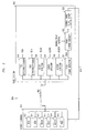
- a mobile terminal 301 communicates over propagation channel 302 with a base station 303 in a wireless communications system 304 operating in accordance with exemplary CDMA2000 standards.
- exemplary CDMA2000 standards Although herein described in conjunction with a system operating under CDMA2000 standards, it should be understood that the present invention could be incorporated in any other type of CDMA system, for example, a UMTS system.
- pluralities of bit streams on individual channels are code division multiplexed using different Walsh codes for transmission to the base station 303.
- these channels include a Fundamental Channel FCH 310 that carries encoded voice in a fixed frame format, a Supplemental Channel SCH 311 that carries packet data when the mobile terminal has such packet data to transmit, a Dedicated Control Channel DCCH 312 that carries control data, a Channel Quality Indicator Channel CQICH 313 on which a downlink received pilot strength is transmitted to the base station 303, an Acknowledgement Channel ACKCH 314 on which and indication of whether or not a received data packet on the downlink has been successfully decoded is transmitted to base station 303, and a Pilot Channel PICH 315 on which the mobile terminal pilot signal is transmitted and which is used for providing an amplitude and phase reference to the base station 303 for the detection of the FCH 310.
- a Fundamental Channel FCH 310 that carries encoded voice in a fixed frame format
- a Supplemental Channel SCH 311 that carries packet data when the mobile terminal has such packet data to transmit
- a Dedicated Control Channel DCCH 312 that carries control data
- each of the code-division-multiplexed channels is separated at the base station 303, individual detectors and/or decoders recover each of the transmitted bit streams.
- FCH detector/decoder 316 recovers the transmitted encoded voice channel frame-formatted bit stream when that channel is transmitting.
- CQI detector 317 recovers the transmitted CQI and ACK detector 318 recovers the transmitted ACK.
- the SCH detector/decoder 319 recovers the packet data transmitted on the SCH channel, when that channel is being used for data transmission, and the DCCH detector 320 recovers the signal transmitted on the dedicated control channel.
- the FCH and the SCH are discontinuous channels that cannot be used to derive a continuous frame error signal from frame-by-frame comparisons of sequentially received frames with the CRC within each frame.
- step up and step down signals cannot be derived from these either channel and transmitted to the mobile terminal 301 to control the mobile terminal E b /N 0 pilot level as is done in the previously described prior art.
- the base station 303 instead monitors the continuously received pilot signal to determine whether the pilot signal has been received in error.
- a derived error signal is then transmitted by base station 303 back to the mobile terminal 301, which is informed to step up or step down its E b /N 0 pilot level by predetermined fixed amounts so as to maintain a desired FER on the pilot signal.
- a PICH frame detector 321 imposes a frame format consisting of a fixed number of bits per frame on the detected bit stream received on PICH 315.
- a frame checker 322 then compares the bit pattern of each frame with the known bit pattern of the pilot signal. For example, for the CDMA2000 system, the transmitted pilot signal consists of continuous "1's". Thus, by comparing the bit pattern in each pilot signal frame with the known and expected pilot bit pattern, an error signal can be developed.
- a mobile target E b /N 0 setup device 323 then derives a step-up or step-down signal in response to each frame comparison, which is transmitted by the base station 303 on the downlink channel 324 to the mobile terminal 301.
- the base station 303 For each comparison in which a pilot frame is determined to be in error, the base station 303 sends the mobile terminal a step up signal. The mobile terminal 303 in response thereto increases its E b /N 0 pilot level by (1-Y) ⁇ dB. On the other hand, for each comparison in which a pilot frame is determined to be correct, the base station sends the mobile terminal a step down signal. The mobile terminal 303 in response thereto decreases its E b /N 0 level by Y ⁇ dB.
- This described methodology is effective if a frame error rate for the pilot frames of Y can always be achieved for E b /N 0 values when a frame error rate for FCH frames of X is achieved, regardless of how and where the mobile terminal 301 and the base station 303 with which it is communicating are located relative to each other and regardless of over what type of propagation channel 302 they are communicating.
- a Y is found by selecting a pilot frame size that gives the desired result.
- such a frame size would be one that, for the same E b /N 0 level for all installation scenarios, gives the same frame error rate on the pilot channel as the desired frame error rate on the FCH, such as 10 -2 .
- FIGS. 4 and 5 illustrate simulations for two different channel scenarios.
- FIG. 4 assumes an Additive White Gaussian Noise (AWGN) channel and
- FIG. 5 assumes a multi-path Rayleigh fading channel.
- Curve 401 in FIG. 4 shows frame error rate versus E b /N 0 for the FCH on such an AWGN channel and
- curve 501 in FIG. 5 shows frame error rate versus E b /N 0 on the multi-path Rayleigh fading channel.
- AWGN Additive White Gaussian Noise
- the E b /N 0 pilot level will be adjusted to approximately 2 dB when the mobile terminal and the base station are communicating over an AWGN channel, and to approximately 5 dB when the mobile terminal and the base station are communicating over a multi-path Rayleigh fading channel.
- Curves 402, 403 and 404 show the simulated pilot frame error rate versus E b /N 0 for 8 bit, 12 bit and 20 bit pilot frames, respectively on the AWGN channel
- curves 502, 503 and 504 show the simulated pilot frame error rate versus E b /N 0 for 8 bit, 12 bit and 20 bit pilot frames, respectively, on the multi-path Rayleigh fading channel.
- pilot frame error rate versus E b /N 0 curves for each frame length in FIGS. 4 and 5 it can be observed that for a FCH frame error rate of 10 -2 only a pilot frame length of approximately 12 bits yields a pilot frame error rate that is equal in both figures at the E b /N 0 level in each that is associated with that FCH frame error rate.
- a pilot frame error rate of .5 x 10 -2 is equivalent to the FCH frame error rate of 10 -2 for both scenarios.
- a 12 bit pilot frame is used and the frame error signal generated there from is used to set and maintain the E b /N 0 pilot level of the mobile terminal at a value that yields a .5 x 10 -2 frame error rate on that pilot channel.
- the pilot E b /N 0 level By so maintaining the pilot E b /N 0 level, the frame error rate of the FCH when an encoded voice signal is transmitted on it will be maintained at the desired 10 -2 , and the levels of the FCH, the SCH and the other channels, which power levels are individually controlled relative to the pilot E b /N 0 level, will be maintained at their proper transmit levels.
- the error signal derived at the base station from the pilot signal is used in the embodiment described above to control the mobile terminal's E b /N 0 pilot level
- the error signal can also be used by the base station directly as a measure of uplink signal quality and can be a factor used to determine whether communication between the base station and the mobile terminal should continue or should be discontinued. That error signal can take different forms and can indicate a degree of mismatch between the framed pilot with the known pilot portion.
- processing circuitry required to implement and use the described invention may be implemented in application specific integrated circuits, software-driven processing circuitry, firmware, programmable logic devices, hardware, discrete components or arrangements of the above components as would be understood by one of ordinary skill in the art with the benefit of this disclosure.
- processing circuitry required to implement and use the described invention may be implemented in application specific integrated circuits, software-driven processing circuitry, firmware, programmable logic devices, hardware, discrete components or arrangements of the above components as would be understood by one of ordinary skill in the art with the benefit of this disclosure.
- Those skilled in the art will readily recognize that these and various other modifications, arrangements and methods can be made to the present invention without strictly following the exemplary applications illustrated and described herein and without departing from the spirit and scope of the present invention. It is therefore contemplated that the appended claims will cover any such modifications or embodiments as fall within the true scope of the invention.
Landscapes
- Engineering & Computer Science (AREA)
- Computer Networks & Wireless Communication (AREA)
- Signal Processing (AREA)
- Mobile Radio Communication Systems (AREA)
Applications Claiming Priority (2)
| Application Number | Priority Date | Filing Date | Title |
|---|---|---|---|
| US10/798,166 US7266723B2 (en) | 2004-03-11 | 2004-03-11 | Method and apparatus for controlling uplink power to maintain desired frame error rate in a wireless communications system |
| US798166 | 2004-03-11 |
Publications (2)
| Publication Number | Publication Date |
|---|---|
| EP1575186A1 true EP1575186A1 (de) | 2005-09-14 |
| EP1575186B1 EP1575186B1 (de) | 2009-02-18 |
Family
ID=34827657
Family Applications (1)
| Application Number | Title | Priority Date | Filing Date |
|---|---|---|---|
| EP05251293A Expired - Fee Related EP1575186B1 (de) | 2004-03-11 | 2005-03-03 | Verfahren und Gerät zur Sendeleistungssteuerung in einer Aufwärtsverbindung um die gewünschte Rahmenfehlerrateeinstellungen in einem drahtlosen Kommunikationssystem zu bewahren |
Country Status (6)
| Country | Link |
|---|---|
| US (1) | US7266723B2 (de) |
| EP (1) | EP1575186B1 (de) |
| JP (1) | JP4758664B2 (de) |
| KR (1) | KR101100972B1 (de) |
| CN (1) | CN1674460B (de) |
| DE (1) | DE602005012748D1 (de) |
Families Citing this family (7)
| Publication number | Priority date | Publication date | Assignee | Title |
|---|---|---|---|---|
| US20050163194A1 (en) * | 2004-01-28 | 2005-07-28 | Qualcomm Incorporated | Interference estimation in a wireless communication system |
| US8085831B2 (en) * | 2004-05-17 | 2011-12-27 | Qualcomm Incorporated | Interference control via selective blanking/attenuation of interfering transmissions |
| US7548760B2 (en) | 2006-01-13 | 2009-06-16 | Alcatel-Lucent Usa Inc. | Method of reverse link dynamic power control in a wireless communication system using quality feedback from a delay-sensitive traffic stream or overhead channel |
| CN101009523B (zh) * | 2006-01-23 | 2011-08-10 | 中兴通讯股份有限公司 | 一种自动测量移动通信终端解调性能的装置及方法 |
| JP4814734B2 (ja) * | 2006-09-06 | 2011-11-16 | 株式会社エヌ・ティ・ティ・ドコモ | 通信装置 |
| US8213979B1 (en) | 2007-08-15 | 2012-07-03 | Sprint Spectrum L.P. | Method and system for forward link and/or reverse link power control |
| EP2223438B1 (de) * | 2007-11-26 | 2014-11-19 | Telefonaktiebolaget LM Ericsson (publ) | Sendeleistungsregelung in der aussenschleife für e-dch |
Citations (3)
| Publication number | Priority date | Publication date | Assignee | Title |
|---|---|---|---|---|
| EP0893889A2 (de) * | 1997-07-19 | 1999-01-27 | Matsushita Electric Industrial Co., Ltd. | Verfahren und Vorrichtung für Sendeleistungsregelung in einem CDMA Nachrichtenübertragungssystem |
| WO1999012275A1 (en) * | 1997-09-02 | 1999-03-11 | Motorola Inc. | Adaptive power control of a pilot sub-channel |
| EP1501208A1 (de) * | 2003-07-23 | 2005-01-26 | NEC Corporation | Verfahren zur Leistungsregelung (äusserer Regelkreis) in einer diskontinuierlichen Übertragung (DTX) unter Verwendung von Pilotbits |
Family Cites Families (6)
| Publication number | Priority date | Publication date | Assignee | Title |
|---|---|---|---|---|
| JP3660690B2 (ja) * | 1996-06-27 | 2005-06-15 | 株式会社エヌ・ティ・ティ・ドコモ | 送信電力制御装置 |
| US5991284A (en) * | 1997-02-13 | 1999-11-23 | Qualcomm Inc. | Subchannel control loop |
| JP3358565B2 (ja) * | 1998-11-02 | 2002-12-24 | 日本電気株式会社 | 送信電力制御方法、送信電力制御装置、移動局、基地局及び制御局 |
| JP2000151557A (ja) * | 1998-11-13 | 2000-05-30 | Nec Corp | Cdma通信装置 |
| US6898192B2 (en) * | 2000-12-29 | 2005-05-24 | Nortel Networks Limited | Method and apparatus for improving fast forward link power control during variable rate operation of CDMA systems |
| JP2005005762A (ja) * | 2003-06-09 | 2005-01-06 | Fujitsu Ltd | 送信電力制御方法及び装置 |
-
2004
- 2004-03-11 US US10/798,166 patent/US7266723B2/en not_active Expired - Fee Related
-
2005
- 2005-03-03 DE DE602005012748T patent/DE602005012748D1/de active Active
- 2005-03-03 EP EP05251293A patent/EP1575186B1/de not_active Expired - Fee Related
- 2005-03-10 KR KR1020050019890A patent/KR101100972B1/ko active IP Right Grant
- 2005-03-10 CN CN2005100544302A patent/CN1674460B/zh not_active Expired - Fee Related
- 2005-03-11 JP JP2005068305A patent/JP4758664B2/ja not_active Expired - Fee Related
Patent Citations (3)
| Publication number | Priority date | Publication date | Assignee | Title |
|---|---|---|---|---|
| EP0893889A2 (de) * | 1997-07-19 | 1999-01-27 | Matsushita Electric Industrial Co., Ltd. | Verfahren und Vorrichtung für Sendeleistungsregelung in einem CDMA Nachrichtenübertragungssystem |
| WO1999012275A1 (en) * | 1997-09-02 | 1999-03-11 | Motorola Inc. | Adaptive power control of a pilot sub-channel |
| EP1501208A1 (de) * | 2003-07-23 | 2005-01-26 | NEC Corporation | Verfahren zur Leistungsregelung (äusserer Regelkreis) in einer diskontinuierlichen Übertragung (DTX) unter Verwendung von Pilotbits |
Also Published As
| Publication number | Publication date |
|---|---|
| EP1575186B1 (de) | 2009-02-18 |
| CN1674460B (zh) | 2011-09-14 |
| JP4758664B2 (ja) | 2011-08-31 |
| KR20060043807A (ko) | 2006-05-15 |
| KR101100972B1 (ko) | 2011-12-29 |
| JP2005260974A (ja) | 2005-09-22 |
| US7266723B2 (en) | 2007-09-04 |
| DE602005012748D1 (de) | 2009-04-02 |
| CN1674460A (zh) | 2005-09-28 |
| US20050204192A1 (en) | 2005-09-15 |
Similar Documents
| Publication | Publication Date | Title |
|---|---|---|
| CN100456649C (zh) | 无线通信系统内减少干扰的方法和装置 | |
| US7657277B2 (en) | Method and system for power control in a communication system | |
| KR101004970B1 (ko) | 통신 시스템에서의 다중 포맷 채널을 이용한 간섭 감소와전력 제어 | |
| US7746831B2 (en) | Method and apparatus for controlling gain level of a supplemental channel in a CDMA communication system | |
| FI105368B (fi) | Tehonsäätö matkaviestinjärjestelmässä | |
| KR101108390B1 (ko) | 외부 루프 전력 제어를 위한 방법 및 시스템 | |
| BR0011968B1 (pt) | Equipamento e método para ajustar um limite de relação sinal/interferência (sir) | |
| KR20050098943A (ko) | 무선 통신 시스템에서 외부 회로 전력 제어를 실행하는시스템 및 방법 | |
| EP1575186A1 (de) | Verfahren und Gerät zur Sendeleistungssteuerung in einer Aufwärtsverbindung um die gewünschte Rahmenfehlerrateeinstellungen in einem drahtlosen Kommunikationssystem zu bewahren | |
| JP2005535178A5 (de) | ||
| JP2002016545A (ja) | 送信電力制御方法および移動通信システム | |
| EP1964280A2 (de) | System und verfahren zur bestimmung der abwärtsstrecken-signalisierungsleistung in einem funkkommunikationsnetz | |
| JP5558945B2 (ja) | 通信システムにおける電力制御のための方法およびシステム | |
| US20020147025A1 (en) | Systems and methods for base station signal transmission power control | |
| EP1494370A1 (de) | Kommunikationseinheit und verfahren zur steuerung der leistung in äusserer schleife | |
| JP5258581B2 (ja) | ハンドオフ時の電力制御コマンド向上のための消去表示ビットの繰返しの使用 | |
| CN1774874B (zh) | 无线通信系统内减少信道间干扰的方法和装置 | |
| KR20050007980A (ko) | 복합 자동 재전송 방식 이동통신 시스템에서 트래픽데이터 재전송 장치 및 방법 | |
| KR20020014813A (ko) | Cdma 통신 시스템에서의 전송 전력 제어 방법 및 장치 |
Legal Events
| Date | Code | Title | Description |
|---|---|---|---|
| PUAI | Public reference made under article 153(3) epc to a published international application that has entered the european phase |
Free format text: ORIGINAL CODE: 0009012 |
|
| 17P | Request for examination filed |
Effective date: 20050319 |
|
| AK | Designated contracting states |
Kind code of ref document: A1 Designated state(s): AT BE BG CH CY CZ DE DK EE ES FI FR GB GR HU IE IS IT LI LT LU MC NL PL PT RO SE SI SK TR |
|
| AX | Request for extension of the european patent |
Extension state: AL BA HR LV MK YU |
|
| AKX | Designation fees paid |
Designated state(s): DE FR GB |
|
| 17Q | First examination report despatched |
Effective date: 20060915 |
|
| GRAP | Despatch of communication of intention to grant a patent |
Free format text: ORIGINAL CODE: EPIDOSNIGR1 |
|
| GRAS | Grant fee paid |
Free format text: ORIGINAL CODE: EPIDOSNIGR3 |
|
| GRAA | (expected) grant |
Free format text: ORIGINAL CODE: 0009210 |
|
| AK | Designated contracting states |
Kind code of ref document: B1 Designated state(s): DE FR GB |
|
| REG | Reference to a national code |
Ref country code: GB Ref legal event code: FG4D |
|
| REF | Corresponds to: |
Ref document number: 602005012748 Country of ref document: DE Date of ref document: 20090402 Kind code of ref document: P |
|
| RAP4 | Party data changed (patent owner data changed or rights of a patent transferred) |
Owner name: LUCENT TECHNOLOGIES INC. |
|
| PLBE | No opposition filed within time limit |
Free format text: ORIGINAL CODE: 0009261 |
|
| STAA | Information on the status of an ep patent application or granted ep patent |
Free format text: STATUS: NO OPPOSITION FILED WITHIN TIME LIMIT |
|
| 26N | No opposition filed |
Effective date: 20091119 |
|
| REG | Reference to a national code |
Ref country code: GB Ref legal event code: 732E Free format text: REGISTERED BETWEEN 20131121 AND 20131127 |
|
| REG | Reference to a national code |
Ref country code: FR Ref legal event code: CD Owner name: ALCATEL-LUCENT USA INC. Effective date: 20131122 |
|
| REG | Reference to a national code |
Ref country code: FR Ref legal event code: GC Effective date: 20140410 |
|
| REG | Reference to a national code |
Ref country code: FR Ref legal event code: RG Effective date: 20141015 |
|
| REG | Reference to a national code |
Ref country code: FR Ref legal event code: PLFP Year of fee payment: 11 |
|
| REG | Reference to a national code |
Ref country code: FR Ref legal event code: PLFP Year of fee payment: 12 |
|
| REG | Reference to a national code |
Ref country code: FR Ref legal event code: PLFP Year of fee payment: 13 |
|
| REG | Reference to a national code |
Ref country code: FR Ref legal event code: PLFP Year of fee payment: 14 |
|
| PGFP | Annual fee paid to national office [announced via postgrant information from national office to epo] |
Ref country code: GB Payment date: 20200219 Year of fee payment: 16 Ref country code: DE Payment date: 20200218 Year of fee payment: 16 |
|
| PGFP | Annual fee paid to national office [announced via postgrant information from national office to epo] |
Ref country code: FR Payment date: 20200214 Year of fee payment: 16 |
|
| REG | Reference to a national code |
Ref country code: DE Ref legal event code: R119 Ref document number: 602005012748 Country of ref document: DE |
|
| GBPC | Gb: european patent ceased through non-payment of renewal fee |
Effective date: 20210303 |
|
| PG25 | Lapsed in a contracting state [announced via postgrant information from national office to epo] |
Ref country code: GB Free format text: LAPSE BECAUSE OF NON-PAYMENT OF DUE FEES Effective date: 20210303 Ref country code: FR Free format text: LAPSE BECAUSE OF NON-PAYMENT OF DUE FEES Effective date: 20210331 Ref country code: DE Free format text: LAPSE BECAUSE OF NON-PAYMENT OF DUE FEES Effective date: 20211001 |