EP1575136B1 - Tap device - Google Patents
Tap device Download PDFInfo
- Publication number
- EP1575136B1 EP1575136B1 EP04405139A EP04405139A EP1575136B1 EP 1575136 B1 EP1575136 B1 EP 1575136B1 EP 04405139 A EP04405139 A EP 04405139A EP 04405139 A EP04405139 A EP 04405139A EP 1575136 B1 EP1575136 B1 EP 1575136B1
- Authority
- EP
- European Patent Office
- Prior art keywords
- connector
- branching
- contact
- clamp
- female
- Prior art date
- Legal status (The legal status is an assumption and is not a legal conclusion. Google has not performed a legal analysis and makes no representation as to the accuracy of the status listed.)
- Expired - Lifetime
Links
- 230000000694 effects Effects 0.000 claims abstract description 5
- 238000009413 insulation Methods 0.000 claims description 12
- 238000006073 displacement reaction Methods 0.000 claims description 10
- 238000003825 pressing Methods 0.000 claims description 5
- 238000004080 punching Methods 0.000 claims description 3
- 238000005520 cutting process Methods 0.000 abstract description 13
- 239000004020 conductor Substances 0.000 abstract 1
- 238000004519 manufacturing process Methods 0.000 description 10
- 239000002184 metal Substances 0.000 description 7
- 229910052751 metal Inorganic materials 0.000 description 7
- 230000008901 benefit Effects 0.000 description 3
- 238000004049 embossing Methods 0.000 description 3
- 210000001520 comb Anatomy 0.000 description 2
- 238000003780 insertion Methods 0.000 description 2
- 230000037431 insertion Effects 0.000 description 2
- 239000000463 material Substances 0.000 description 2
- 238000000034 method Methods 0.000 description 2
- RYGMFSIKBFXOCR-UHFFFAOYSA-N Copper Chemical compound [Cu] RYGMFSIKBFXOCR-UHFFFAOYSA-N 0.000 description 1
- 229910000881 Cu alloy Inorganic materials 0.000 description 1
- 238000005266 casting Methods 0.000 description 1
- 229910052802 copper Inorganic materials 0.000 description 1
- 239000010949 copper Substances 0.000 description 1
- 239000013078 crystal Substances 0.000 description 1
- 230000001419 dependent effect Effects 0.000 description 1
- 238000007373 indentation Methods 0.000 description 1
- 238000009434 installation Methods 0.000 description 1
- 230000007935 neutral effect Effects 0.000 description 1
- 230000002035 prolonged effect Effects 0.000 description 1
- 239000012780 transparent material Substances 0.000 description 1
Images

Classifications
-
- H—ELECTRICITY
- H01—ELECTRIC ELEMENTS
- H01R—ELECTRICALLY-CONDUCTIVE CONNECTIONS; STRUCTURAL ASSOCIATIONS OF A PLURALITY OF MUTUALLY-INSULATED ELECTRICAL CONNECTING ELEMENTS; COUPLING DEVICES; CURRENT COLLECTORS
- H01R9/00—Structural associations of a plurality of mutually-insulated electrical connecting elements, e.g. terminal strips or terminal blocks; Terminals or binding posts mounted upon a base or in a case; Bases therefor
- H01R9/03—Connectors arranged to contact a plurality of the conductors of a multiconductor cable, e.g. tapping connections
- H01R9/031—Connectors arranged to contact a plurality of the conductors of a multiconductor cable, e.g. tapping connections for multiphase cables, e.g. with contact members penetrating insulation of a plurality of conductors
-
- H—ELECTRICITY
- H01—ELECTRIC ELEMENTS
- H01R—ELECTRICALLY-CONDUCTIVE CONNECTIONS; STRUCTURAL ASSOCIATIONS OF A PLURALITY OF MUTUALLY-INSULATED ELECTRICAL CONNECTING ELEMENTS; COUPLING DEVICES; CURRENT COLLECTORS
- H01R13/00—Details of coupling devices of the kinds covered by groups H01R12/70 or H01R24/00 - H01R33/00
- H01R13/02—Contact members
- H01R13/10—Sockets for co-operation with pins or blades
- H01R13/11—Resilient sockets
- H01R13/112—Resilient sockets forked sockets having two legs
-
- H—ELECTRICITY
- H01—ELECTRIC ELEMENTS
- H01R—ELECTRICALLY-CONDUCTIVE CONNECTIONS; STRUCTURAL ASSOCIATIONS OF A PLURALITY OF MUTUALLY-INSULATED ELECTRICAL CONNECTING ELEMENTS; COUPLING DEVICES; CURRENT COLLECTORS
- H01R13/00—Details of coupling devices of the kinds covered by groups H01R12/70 or H01R24/00 - H01R33/00
- H01R13/64—Means for preventing incorrect coupling
- H01R13/645—Means for preventing incorrect coupling by exchangeable elements on case or base
-
- H—ELECTRICITY
- H01—ELECTRIC ELEMENTS
- H01R—ELECTRICALLY-CONDUCTIVE CONNECTIONS; STRUCTURAL ASSOCIATIONS OF A PLURALITY OF MUTUALLY-INSULATED ELECTRICAL CONNECTING ELEMENTS; COUPLING DEVICES; CURRENT COLLECTORS
- H01R31/00—Coupling parts supported only by co-operation with counterpart
- H01R31/02—Intermediate parts for distributing energy to two or more circuits in parallel, e.g. splitter
-
- H—ELECTRICITY
- H01—ELECTRIC ELEMENTS
- H01R—ELECTRICALLY-CONDUCTIVE CONNECTIONS; STRUCTURAL ASSOCIATIONS OF A PLURALITY OF MUTUALLY-INSULATED ELECTRICAL CONNECTING ELEMENTS; COUPLING DEVICES; CURRENT COLLECTORS
- H01R13/00—Details of coupling devices of the kinds covered by groups H01R12/70 or H01R24/00 - H01R33/00
- H01R13/46—Bases; Cases
- H01R13/514—Bases; Cases composed as a modular blocks or assembly, i.e. composed of co-operating parts provided with contact members or holding contact members between them
-
- H—ELECTRICITY
- H01—ELECTRIC ELEMENTS
- H01R—ELECTRICALLY-CONDUCTIVE CONNECTIONS; STRUCTURAL ASSOCIATIONS OF A PLURALITY OF MUTUALLY-INSULATED ELECTRICAL CONNECTING ELEMENTS; COUPLING DEVICES; CURRENT COLLECTORS
- H01R13/00—Details of coupling devices of the kinds covered by groups H01R12/70 or H01R24/00 - H01R33/00
- H01R13/62—Means for facilitating engagement or disengagement of coupling parts or for holding them in engagement
- H01R13/627—Snap or like fastening
- H01R13/6271—Latching means integral with the housing
-
- H—ELECTRICITY
- H01—ELECTRIC ELEMENTS
- H01R—ELECTRICALLY-CONDUCTIVE CONNECTIONS; STRUCTURAL ASSOCIATIONS OF A PLURALITY OF MUTUALLY-INSULATED ELECTRICAL CONNECTING ELEMENTS; COUPLING DEVICES; CURRENT COLLECTORS
- H01R25/00—Coupling parts adapted for simultaneous co-operation with two or more identical counterparts, e.g. for distributing energy to two or more circuits
- H01R25/003—Coupling parts adapted for simultaneous co-operation with two or more identical counterparts, e.g. for distributing energy to two or more circuits the coupling part being secured only to wires or cables
-
- H—ELECTRICITY
- H01—ELECTRIC ELEMENTS
- H01R—ELECTRICALLY-CONDUCTIVE CONNECTIONS; STRUCTURAL ASSOCIATIONS OF A PLURALITY OF MUTUALLY-INSULATED ELECTRICAL CONNECTING ELEMENTS; COUPLING DEVICES; CURRENT COLLECTORS
- H01R4/00—Electrically-conductive connections between two or more conductive members in direct contact, i.e. touching one another; Means for effecting or maintaining such contact; Electrically-conductive connections having two or more spaced connecting locations for conductors and using contact members penetrating insulation
- H01R4/24—Connections using contact members penetrating or cutting insulation or cable strands
- H01R4/2416—Connections using contact members penetrating or cutting insulation or cable strands the contact members having insulation-cutting edges, e.g. of tuning fork type
- H01R4/242—Connections using contact members penetrating or cutting insulation or cable strands the contact members having insulation-cutting edges, e.g. of tuning fork type the contact members being plates having a single slot
- H01R4/2425—Flat plates, e.g. multi-layered flat plates
- H01R4/2429—Flat plates, e.g. multi-layered flat plates mounted in an insulating base
- H01R4/2433—Flat plates, e.g. multi-layered flat plates mounted in an insulating base one part of the base being movable to push the cable into the slot
Abstract
Description
Die Erfindung betrifft eine Abzweigvorrichtung zum elektrisch leitenden Verbinden eines Hauptkabels mit einem Nebenkabel.The invention relates to a branching device for electrically conductive connection of a main cable with a secondary cable.
Es sind verschiedene Arten von Abzweigvorrichtungen dieser Art bekannt, beispielsweise aus den Publikationen WO 00/30218, DE 199 20 768, DE 101 43 363 oder WO 03/021721. Bei all diesen Abzweigvorrichtungen werden Kabeladern des Hauptkabels durch Schneidkontakte kontaktiert. Bei den Abzweigvorrichtungen gemäss WO 00/30218, DE 199 20 768 und DE 101 43 363 ist das Nebenkabel durch eine Buchse-und-Stecker-Verbindung einsteckbar, während bei der Abzweigvorrichtung der WO 03/021721 das Nebenkabel ebenfalls durch einen Schneidkontakt kontaktiert wird, wodurch die Möglichkeit fehlt, das Nebenkabel bedarfsgemäss auszutauschen.Various types of branch devices of this type are known, for example from the publications WO 00/30218, DE 199 20 768, DE 101 43 363 or WO 03/021721. In all of these branching devices, cable cores of the main cable are contacted by cutting contacts. In the branching devices according to WO 00/30218, DE 199 20 768 and DE 101 43 363, the secondary cable can be inserted through a socket-and-plug connection, while in the branching device of WO 03/021721 the secondary cable is also contacted by a cutting contact, whereby the possibility is missing to replace the auxiliary cable as needed.
Bekannte Abzweigvorrichtungen mit Buchse-und-Stecker-Verbindungen zum Nebenkabel benötigen relativ kompliziert geformte Kontaktierungselemente, welche in der Fertigung aufwändig sind. Beispielsweise werden Abschnitte eines geformten Blechs so verbogen bzw. abgeknickt, dass zwischen den flachen Seiten zweier Abschnitte eine Klemmwirkung entsteht. Dies hat nebst der Kompliziertheit des Herstellungsverfahrens den zusätzlichen Nachteil, dass die Federwirkung im wesentlichen aus dem Knick heraus entsteht, was bei andauernder Beanspruchung eine rasche Ermüdung zur Folge haben kann.Known branch devices with socket-and-plug connections to the secondary cable require relatively complicated shaped contacting elements, which are expensive to manufacture. For example, portions of a formed sheet are bent so as to provide a clamping action between the flat sides of two portions. This has, in addition to the complexity of the manufacturing process, the additional disadvantage that the spring action essentially arises out of the bend, which can result in rapid fatigue on prolonged use.
Aus der WO 98/45896 ist eine Abzweigvorrichtung bekannt, bei welcher Kabeladern eines flachen Kabels durch Kontaktelemente kontaktiert werden, welche auch einen Gabelkontakt zur Aufnahme eines klingenförmigen Kontaktstiftes aufweist. Die Abzweigvorrichtung ist jedoch nur für spezifische Verkablungssystem geeignet. Auch aus der US 6,142,817 sind Kontaktelemente mit einem Schneidklemmkontakt und einem Gabelkontakt bekannt.From WO 98/45896 a branching device is known in which cable wires of a flat cable are contacted by contact elements, which also has a fork contact for receiving a blade-shaped contact pin. However, the branch device is only suitable for specific cabling systems. Also from US 6,142,817 contact elements with a insulation displacement contact and a fork contact are known.
Ein weiterer Problemkreis betrifft die Kodierung. Es ist bekannt, Buchse-Stecker-Verbindungen mit einer individuellen Kodierungsmöglichkeit zu versehen. Ein Monteur kann durch eine bei der Montage vor Ort vorgenommene Kodierung sicherstellen, dass verschiedene Geräte nur im richtigen Stromnetz eingesteckt werden können. Eine Lösung mit einem abtrennbaren Kodiernocken wird beispielsweise in DE 199 32 243 offenbart. Die Lösung ist aber nur zum Einsatz in einem feststehenden Netz, bspw. einem Niederspannungsnetz geeignet.Another problem area concerns the coding. It is known to provide female-male connections with an individual coding possibility. An installer can ensure that various devices can only be plugged into the correct power supply by means of an on-site coding. A solution with a detachable coding cam is disclosed for example in DE 199 32 243. The solution is only suitable for use in a fixed network, for example. A low-voltage network.
Es ist Aufgabe der Erfindung, eine Abzweigvorrichtung zu schaffen, welche Probleme gemäss dem Stand der Technik überwindet und insbesondere eine kostengünstige Herstellung ermöglicht. In diesem Kontext ist das Schaffen eines Kontaktierungselementes, welches möglichst einfach in der Herstellung ist, ebenfalls eine Aufgabe der Erfindung.It is an object of the invention to provide a branching device, which overcomes problems according to the prior art and in particular allows a cost-effective production. In this context, the creation of a contacting element, which is as simple as possible in the production, also an object of the invention.
Diese Aufgabe wird gelöst durch die Erfindung, wie sie in den Patentansprüchen definiert ist.This object is achieved by the invention as defined in the patent claims.
Gemäss der Erfindung besitzt die Abzweigvorrichtung zum Verbinden eines Hauptkabels mit einem Nebenkabel Kontaktierungselemente, welche je mindestens eine Schneidklemme zum Kontaktieren der Hauptkabeladern sowie mindestens einen Klemmkontakt aufweisen. Der Klemmkontakt ist erfindungsgemäss flach oder blechartig und definiert lokal eine Ebene, wobei die Klemmwirkung - bspw. zwischen zwei Flügelelementen - durch entlang der Ebene wirkende Federkräfte entsteht. Der Klemmkontakt kann ähnlich wie eine Gabelkontakt geformt sein, also beispielsweise als stimmgabelartig ausgestaltetes Blech vorliegen, wobei die Flügelelemente Zinken des stimmgabelartigen Gebildes sind. Zwischen den Zinken bildet sich dann eine Kontaktöffnung, und beim Einführen des zu kontaktierenden Gegenstandes (bspw. Kontaktstiftes) ergibt sich eine Kontaktspreizung der Zinken gegeneinander entgegen der erwähnten Federkraft. Weiter weist die Abzweigvorrichtung ein Gehäuse-Basisteil mit Mitteln zum Führen der Hauptkabeladern auf, wobei die Kontaktierungselemente in das Gehäuse-Basisteil eingepasst sind, wobei das Gehäuse-Basisteil ferner einen Buchsensitz aufweist, in welchen die Buchse eingebracht ist und wobei der Klemmkontakt eine der erwähnten Kontaktstellen der Buchse bildet.According to the invention, the branching device for connecting a main cable to a secondary cable has contacting elements which each have at least one insulation displacement terminal for contacting the main cable cores and at least one Have clamping contact. According to the invention, the clamping contact is flat or sheet-like and locally defines a plane, wherein the clamping action - for example between two wing elements - is created by spring forces acting along the plane. The terminal contact may be shaped similar to a fork contact, that is, for example, present as a tuning fork-like designed sheet, the wing elements are prongs of the tuning fork-like structure. A contact opening then forms between the prongs, and when the object to be contacted is inserted (for example a contact pin), a contact spread of the prongs against each other results against the mentioned spring force. Furthermore, the branching device comprises a housing base part with means for guiding the main cable wires, wherein the contacting elements are fitted in the housing base part, wherein the housing base part further comprises a Buchsensitz, in which the socket is inserted and wherein the clamping contact one of the mentioned Contact points of the socket forms.
Der Begriff "flach" bedeutet in diesem Kontext nicht notwendigerweise, dass der ganze Klemmkontakt strikt in einer einzigen Ebene liegt. Vielmehr kann der Klemmkontakt als ganzes bspw. gebogen oder sogar geknickt sein. Er ist aber lokal blechartig flach, und die Klemmwirkung wird, bspw. an einem Klemmpunkt, wie erwähnt durch Kräfte bewirkt, welche entlang der durch die Blechfläche am Ort des Klemmpunkts definierte Ebene wirken.The term "flat" in this context does not necessarily mean that the entire clamp contact is strictly in a single plane. Rather, the terminal contact as a whole, for example, be bent or even kinked. But it is locally flat sheet-like, and the clamping action is, for example. At a terminal point, as mentioned, caused by forces acting along the plane defined by the sheet surface at the location of the clamping point.
Dadurch, dass der Klemmkontakt erfindungsgemäss flach ist, entstehen wichtige Vorteile bei der Herstellung. Der Klemmkontakt kann aus einem Blech gestanzt oder durch feinschneiden geformt werden, ohne dass das Blech anschliessend massiv verformt werden muss. Ausserdem kann die Klemmwirkung auch bei geringen Blechdicken genügend gross sein, indem die Breite von Flügelelementen (oder Zinken), zwischen denen die Klemmwirkung entsteht, genügend gross gewählt wird. Dies ermöglicht die Verwendung von verhältnismässig dünnen Blechen, was ebenfalls Vorteile mit sich bringen kann. Die stirnseitige Kontaktierung bewirkt auch, dass selbst bei dünnen Blechen im Betrieb eine verhältnismässig kleine Stromdichte vorhanden ist.The fact that the terminal contact according to the invention is flat, there are important advantages in the production. The clamping contact can be punched from a sheet or formed by fine cutting without the sheet must then be massively deformed. In addition, the clamping effect can be sufficiently large, even with small sheet thicknesses, by the width of wing elements (or tines), between which the clamping effect arises, is chosen sufficiently large. This allows the use of relatively thin sheets, which can also bring benefits. The frontal contact also causes a relatively small current density is present even with thin sheets in operation.
Ausserdem entsteht durch die spezifische Geometrie ein gewichtiger weiterer Vorteil: Da der Klemmkontakt entlang einer Ebene ausgeführt ist, kann das Kontaktelement im Wesentlichen ohne grösseren Herstellungsaufwand mit zwei oder mehreren Klemmkontakten versehen werden. Dadurch eignet er sich in idealer Weise auch als Bestandteil von Mehrfachsteckdosen-Ausführungformen, in denen ein einziges Kontaktelement den Kontakt zu mehreren Buchsen herstellt. Dies ist vorteilhaft sowohl bei der Herstellung als auch bei der Montage von Systemen mit der erfindungsgemässen Abzweigvorrichtung. Ausserdem kann das Konzept auf Kontaktierungssysteme mit beispielsweise einer Abzweigvorrichtung und mit Mehrfachsteckdosenmodulen ausgeweitet werden. Ein erfindungsgemässer Kontakt in einem Mehrfachsteckdosenmodul besitzt ebenfalls Klemmkontakte der vorstehend beschriebenen Art und kann ebenfalls aus einem Blech gestanzt oder durch feinschneiden hergestellt sein.In addition, due to the specific geometry, a weighty further advantage arises: since the clamping contact is made along one plane, the contact element can be provided with two or more clamping contacts essentially without major manufacturing effort. As a result, it is ideally suited as part of multiple socket outlet designs in which a single contact element makes contact with a plurality of sockets. This is advantageous both in the manufacture and in the assembly of systems with the inventive branching device. In addition, the concept can be extended to contacting systems with, for example, a branching device and with multiple socket modules. A contact according to the invention in a multiple socket module likewise has terminal contacts of the type described above and can likewise be punched from a sheet or produced by fine cutting.
Das Kontaktelement ist gemäss einer bevorzugten Ausführungsform einstückig ausgeformt. Es kann daher auch als Ganzes aus einem Blech gestanzt oder durch feinschneiden hergestellt werden, wobei anschliessend ggf. die Schneiden der Schneidklemme durch Prägen oder Schleifen gefertigt werden können und wobei ggf. die Ebene der Schneidklemme und/oder eines Klemmkontakts gegenüber der ursprünglichen Blechebene verdreht wird. Letzteres kann in einem Prägeprozess geschehen.The contact element is integrally formed according to a preferred embodiment. It can therefore also be punched as a whole from a metal sheet or produced by fine cutting, then optionally the cutting edges of the cutting terminal can be made by embossing or grinding and possibly where the plane of the insulation displacement terminal and / or a terminal contact is rotated relative to the original sheet metal plane , The latter can happen in an embossing process.
Das Abzweigsystem besitzt vorzugsweise ein mehrstufiges Kodiersystem. Eine erste Stufe besteht aus werkseitig angebrachten mechanischen Kodierungen, bspw. Kerben im Stecker, welche parallel zu einer Steckerachse verlaufen und Kämmen in der Buchse entsprechen (bzw. bei falscher Kodierung nicht entsprechen) oder umgekehrt. Die zweite Stufe besteht aus entfernbaren und/oder hinzufügbaren Elementen, bspw. steckerseitig vorhandene Nocken, deren laterale Position derjenigen von buchsenseitig einbringbaren Stiften entspricht.The branching system preferably has a multi-stage coding system. A first stage consists of factory-mounted mechanical coding, for example notches in the plug, which run parallel to a plug axis and correspond to combing in the socket (or do not correspond to incorrect coding) or vice versa. The second stage consists of removable and / or added elements, for example plug-in cams, whose lateral position corresponds to that of bush-side insertable pins.
Im Folgenden werden Ausführungsformen der Erfindung bezugnehmend auf Zeichnungen beschrieben. In den Zeichnungen zeigen:
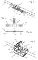
- Fig. 1: Eine Ansicht der erfindungsgemässen Abzweigvorrichtung, wobei zur Wahrung der Übersicht sämtliche Gehäuseteile weggelassen wurden
- Fig. 2a und 2b: Ansichten eines Kontaktierungselementes der Vorrichtung gemäss
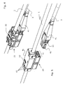
Figur 1. - Fig. 3: Eine Ansicht der Vorrichtung, gemäss Fig. 1, wobei die Kabeladern des Hauptkabels im Gehäuse-Basisteil geführt werden und wobei auch ein Beschaltungsdeckel gezeichnet ist.
- Fig. 4: Eine Ansicht derselben Vorrichtung, wobei sich der Beschaltungsdeckel in der Endstellung befindet und wobei auch ein in die Buchse eingeführter Stecker gezeichnet ist.
- Fig. 5: Die Vorrichtung mit gezogenem Stecker inklusive Abdeckung.
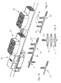
- Fig. 6, 6a und 6b: Eine Ausführungsform der erfindungsgemässen Vorrichtung zur Verwendung mit Netzsteckern und Detailansichten der zugehörigen Kontaktierungselemente.
- Fig. 7, 7a und 7b: Eine der Ausführungsgsform von Fig. 6 ähnliche Ausführungsform, wobei die Eigenschaft der Stapelbarkeit sichtbar wird.
- Fig. 8 eine weitere Ausführungsform des Kontaktierungselementes.
- Fig. 9 eine Abzweigvorrichtung mit zwei Mehrfachbuchsen, so dass sich ein Kontaktierungssystem ergibt.
- Fig. 10 Ein Kontakt für ein Kontaktierungssystem.
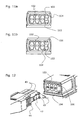
- Fig. 11a und 11b Frontansichten einer Steckerbuchse mit Kodierung.
- Fig. 12 eine Ansicht eines Ausschnitts aus der Vorrichtung gemäss Fig. 5.
- Fig. 1: A view of the inventive branching device, wherein all housing parts have been omitted to maintain the overview
- 2a and 2b: views of a contacting element of the device according to FIG. 1
- Fig. 3: A view of the device, according to FIG. 1, wherein the cable cores of the main cable are guided in the housing base part and wherein a wiring cover is drawn.
- Fig. 4: A view of the same device, wherein the wiring cover is in the end position and wherein a plug inserted into the socket is drawn.
- Fig. 5: The device with drawn plug including cover.
- Fig. 6, 6a and 6b: An embodiment of the inventive device for use with power plugs and detail views of the associated contacting elements.
- Figures 7, 7a and 7b: An embodiment similar to the embodiment of Figure 6 showing the property of stackability.
- Fig. 8 shows a further embodiment of the contacting element.
- Fig. 9 shows a branching device with two multiple sockets, so that there is a contacting system.
- Fig. 10 A contact for a contacting system.
- 11a and 11b front views of a socket with coding.
- 12 is a view of a detail of the device according to FIG. 5.
Das Prinzip einer erfindungsgemässen Abzweigvorrichtung wird in Figur 1 sichtbar. Ein Hauptkabel 1 mit Hauptkabeladern 2 wird von einem Nebenkabel 3 mit Nebenkabeladern 4 kontaktiert. Hierzu dienen Kontaktierungselemente 5, welche von Steckerkontakten 6 elektrisch kontaktierbar sind. Die Steckerkontakte sind bspw. über Klemmen 7 fest mit den Nebenkabeladern 4 verbunden.The principle of a branching device according to the invention is visible in FIG . A
Wie das in den Figuren 2a und 2b sichtbar ist, besitzt jedes Kontaktierungselement 5 eine Schneidklemme 11 zum Kontaktieren der Hautpkabeladern sowie mindestens einen Klemmkontakt 12, in der gezeichneten Ausführungsform sind es zwei Klemmkontakte. Das Kontaktierungselement 5 ist einstückig ausgebildet, und zwar als ein aus einem Blech ausgestanztes Stanzteil. Die auf der Innenseite der Schneidklemme 11 ausgebildeten Schneiden sind nach dem Stanzen durch Prägen oder Schleifen geschärft worden. Die Schneidklemme ist - im gezeichneten Beispiel um ca. 45° - gegenüber der Blechebene abgedreht. Dies ermöglicht eine Geometrie der Abzweigvorrichtung wie in Figur 1 gezeichnet, also mit zum Hauptkabel parallel verlaufenden Steckerkontakten 6. Es sind aber auch andere Geometrien denkbar, bspw. ohne abgedrehte Scheidklemme und mit vom Hauptkabel senkrecht wegführenden Steckerkontakten, oder mit Scheidklemmen, die um einen anderen Winkel als 45° gegenüber der Blechebene verdreht sind, beispielsweise um einen Winkel zwischen 45° und 90°.As can be seen in Figures 2a and 2b , each contacting
Die Klemmkontakte 12 des Kontaktierungselementes sind im Unterschied zum Stand der Technik mindestens lokal flach, so dass eine Ebene definiert wird. Im gezeichneten Beispiel ist der Klemmkontakt in der Ebene ähnlich einer Stimmgabel mit zwei Zinken ausgeformt. Eine Klemmwirkung für die Steckerkontakte 6 entsteht zwischen den zwei Zinken durch Federkräfte entlang der Ebene, ähnlich wie bei einem Gabelkontakt. Die Klemmkontakte können - anders als in der gezeichneten Ausführungsform - ebenfalls gegenüber der ursprünglichen Blechebene verdreht sein.In contrast to the prior art, the clamping
Das Material, aus dem das Kontaktierungselement gefertigt ist, ist beispielsweise Kupfer oder eine Kupferlegierung. Die Dicke des Blechs liegt beispielsweise zwischen 0.5 mm und 1.2 mm, vorzugsweise 0.7 mm bis 0.9 mm. Die Breite der Zinken ist so gewählt, dass eine gewünschte Federkraft entsteht und ist daher abhängig von der Blechdicke von der Länge der Zinken und vom Material. Sie beträgt bspw. ca. 1 mm bis 3 mm, vorzugsweise ca. 1.7 mm bis 2.4 mm. Die Länge der Zinken kann bspw. zwischen 12 mm und 25 mm betragen.The material from which the contacting element is made is, for example, copper or a copper alloy. The thickness of the sheet is, for example, between 0.5 mm and 1.2 mm, preferably 0.7 mm to 0.9 mm. The width of the tines is chosen so that a desired spring force is produced and is therefore dependent on the sheet thickness of the length of the tines and the material. It is, for example, about 1 mm to 3 mm, preferably about 1.7 mm to 2.4 mm. The length of the tines may, for example, be between 12 mm and 25 mm.
Figur 3 zeigt eine Ansicht der Bauteile gemäss Fig. 1, wobei die Kabeladern des Hauptkabels in einem Gehäuse-Basisteil 21 geführt werden und wobei auch ein Beschaltungselement, nämlich ein Beschaltungsdeckel 22 gezeichnet ist. Das Gehäuse-Basisteil besitzt einen Buchsensitz (in der Figur unten gezeichnet) und eine Hauptkabeladerführung (in der Figur oben) mit Führungsstegen 23. Die Kontaktierungselemente 5 sind im Gehäuse-Basisteil eingepasst, so, dass die Schneidklemmen 11 eine Kabelisolation von zwischen den Führungsstegen 23 geführten Hauptkabeladern durchschneiden und die Hauptkabeladern kontaktieren. Figure 3 shows a view of the components according to FIG. 1, wherein the cable cores of the main cable are guided in a
Der Beschaltungsdeckel 22 dient dazu, über Pressstege 26 die Hauptkabeladern entgegen einem Widerstand genügend tief zwischen die Führungsstege einzudrücken, so, dass sie verlässlich durch die Schneidklemmen 11 kontaktiert sind. Der Beschaltungsdeckel 22 besitzt Schwenkachsen 24, welche in stirnseitigen Einbuchtungen 25 der Führungsstege eingehängt werden, woraufhin der Beschaltungsdeckel um die Schwenkachsen schwenkbar geführt wird. In einer Endstellung ist der Beschaltungsdeckel durch Verrastungen 27 fixiert. Denkbar sind auch Beschaltungsdeckel respektive Beschaltungsmittel, durch welche mittels Pressen oder Presszangen vertikal beschaltet werden kann.The
Im Buchsensitz sind zwei Buchsen 31 eingebracht, in welche Steckerkontakte 6 eines Steckers einführbar sind. In der gezeichneten Anordnung ist je eine Buchse - bezüglich der Richtung des Hauptkabels - nach vorne und nach hinten gerichtet. Die Kontaktierungselemente und die Steckerbuchsen sind so gegenseitig positioniert, dass die eingeführten Steckerkontakte zwischen den Zinken der Klemmkontakte geführt werden und diese somit kontaktieren.In Buchsensitz two
Figur 4 das ganze Abzweigsystem - also die Abzweigvorrichtung inklusive dazugehörigem Stecker, wobei sich der Beschaltungsdeckel 22 in der Endstellung befindet und wobei der Stecker 41 in die Buchse eingeführt gezeichnet ist. Figure 4 shows the whole branching system - ie the branching device including the associated plug, wherein the
In Figur 5 sieht man die Abzweigvorrichtung 10 als Ganzes mit gezogenem Stecker 41 inklusive Abdeckung 51. Die Abdeckung besitzt ein transparentes Fenster 52, das eine Sicht auf die Hauptkabeladern ermöglicht. Dies bietet einem Kontrolleur die Möglichkeit, das richtige Verlegen der Kabeladern zu überprüfen, ohne die Abdeckung zu öffnen. Im gezeichneten Ausführungsbeispiel sind auf dem Fenster noch Markierungen 53 mit Leiterbezeichnungen angebracht, die auf die korrekte Position von Phase, Nulleiter und Erde oder von anders gearteten Kabeladern verweisen. Aus Herstellungsgründen kann die Abdeckung als ganzes einem transparenten Material gefertigt sein, wobei bspw. nur das Fenster so geschliffen ist, dass eine glasklare Sicht auf die Kabeladern möglich ist. FIG. 5 shows the branching
Der Beschaltungsdeckel kann, muss aber nicht an seiner Endstellung verbleiben, wenn die Abdeckung montiert und die Abzweigvorrichtung gebrauchsfertig ist.The wiring cover may or may not remain at its end position when the cover is mounted and the branch device is ready for use.
Für gewisse Installationen werden in den Vorschriften die Verrastung der Stecker mit den Steckdosen (also den Buchsen für Netzkabel) verlangt. Bei bekannten Produkten wird die Verrastung mit einem zusätzlichen Rastteil gelöst. Die gezeichnete Ausführungsform der Erfindung beinhaltet eine Rastklinke 42, die am Stecker angespritzt ist. Alternativ dazu kann die Rastklinke als separat gefertigtes bspw. metallisches Einzelteil vorhanden sein. Die Rastklinke wirkt mit einer auf der Steckdoseninnenseite vorhandenen Rastkante (nicht sichtbar) zusammen und bewirkt eine Verrastung. Diese kann nur gelöst werden, indem ein Pressteil 44 gegen die Steckerinnenseite gedrückt wird, wodurch die Rastklinke nach innen geschoben wird. Aufgrund der angespritzten Rastklinke entstehen bei der Fertigung keine Mehrkosten für die Verrastung. Dieses Prinzip der am Stecker angespritzten Rastklinke kann auch für Kontaktierungssysteme verwendet werden, welche ansonsten nicht gemäss der Erfindung ausgestaltet sind.For certain installations, the regulations require the locking of the plugs with the sockets (that is, the sockets for power cables). In known products, the locking is achieved with an additional locking part. The illustrated embodiment of the invention includes a
In der gezeichneten, bevorzugten Ausführungsform ist die Abzweigvorrichtung für dreipolige Stromkabel bestimmt. Die erfindungsgemässe Ausgestaltung der Abzweigvorrichtung kann aber selbstverständlich auch für andere Kabelsysteme verwendet werden, beispielsweise für zweipolige oder fünfpolige Stromkabel, für Datenkabel mit beliebiger Anzahl Kabeladern, für Lautsprecherkabel etc.In the illustrated preferred embodiment, the branching device is intended for three-pole power cables. Of course, the embodiment of the branching device according to the invention can also be used for other cable systems, for example for two-pole or five-pole power cables, for data cables with any number of cable cores, for loudspeaker cables, etc.
Die Ausführungsform der erfindungsgemässen Abzweigvorrichtung gemäss Figur 6 besitzt ebenfalls Kontaktierungselemente und ein Gehäuse der vorstehend beschriebenen Art. Sie ist jedoch im Unterschied zur Ausführungsform der Figuren 1 bis 5 für Normstecker 61 (abgebildet sind Steckdosen und Stecker gemäss Schweizer Norm) ausgebildet. Dies bedingt einige Konstruktionsänderungen. So müssen die Zinken der Klemmkontakte weiter auseinander gespreizt sein, da die Kontaktstifte 62 der Normstecker üblicherweise rund sind, wie das in Figur 6a dargestellt ist. Ausserdem sind die Kontaktstifte nicht auf gleicher Höhe angeordnet, so dass die Klemmkontakte 12 in entsprechend angepassten Positionen sein müssen. Das kann bedingen, dass die Klemmkontakte wie in der Figur gezeichnet zueinander versetzt angebracht sein müssen. In Figur 6b ist eine Anordnung von drei Kontaktierungselementen gezeichnet, wie sie in der Ausführungsform gemäss Figur 6 verwendet wird. Durch diese Anordnung ist sichergestellt, dass die Polung relativ zum Stecker immer gleich ist.The embodiment of the inventive branching device according to Figure 6 also has contacting elements and a housing of the type described above. However, it is in contrast to the embodiment of Figures 1 to 5 for standard plug 61 (shown sockets and plugs according to Swiss standard) are formed. This requires some design changes. Thus, the prongs of the terminal contacts must be further spread apart, since the
In Figur 7 ist dargestellt wie auf Basis der erfindungsgemässen Abzweigvorrichtung ein Kontaktierungssystem entstehen kann, ohne dass massive Konstruktionsänderungen oder raffinierte zusätzliche Teile notwendig wären. Das System beinhaltet stapelbare Module 71, wobei die Kontaktierungselemente 5 durch Kontaktöffnungen 63, 73 in das jeweils benachbarte Modul bzw. die Abzweigvorrichtung 10 eingreifen und ein Kontaktierungselement 5 des banachbarten Moduls bzw. der Abzweigvorrichtung kontaktieren. Die Kontaktierungselemente können dabei einen kombiniert als Schneidklemme und Steckerkontakt ausgebildeten Kontaktschlitz aufweisen, wie das in den Figuren 7a und 7b illustriert ist. Dann können für Abzweigvorrichtung 10 und stapelbare Module 71 identische Kontaktierungselemente verwendet werden. Alternativ dazu können die Kontakte der Module anstelle der genannten Kontaktschlitze Klemmkontakte aufweisen, die beispielsweise gleich ausgebildet sind wie die bereits beschriebenen Klemmkontakte, aber gegen diese um ca. 90° verdreht sind. FIG. 7 shows how, based on the branching device according to the invention, a contacting system can be created without massive structural changes or sophisticated additional parts being necessary. The system includes
Die stapelbaren Module 71 besitzen in der gezeichneten Ausführungsform noch Verdreh- und Positionierungsnocken 74 und Rastklappen 75 für die Befestigung des jeweils darüber- bzw. darunterliegenden Moduls.The
Anstelle von stapelbaren Modulen gemäss Figur 7 kann auch die Abzweigvorrichtung selbst mit Mehrfachbuchsen bzw. -steckdosen ausgerüstet sein. In diesen Abzweigvorrichtungen verwendete Kontaktierungselemente sind dann bspw. ausgebildet wie das in der Figur 8 gezeichnete Kontaktierungselement 5 mit sechs als Steckdosen-Kontaktierungen dienenden Klemmkontakten 12.Instead of stackable modules according to FIG. 7, the branching device itself can also be equipped with multiple sockets or sockets. Contacting elements used in these branching devices are then formed, for example, like the contacting
Ein weiteres erweitertes Kontaktierungssystem ist in der Figur 9 gezeichnet. Nebst der Abzweigvorrichtung 10 sind zwei aneinanderreihbare Mehrfachsteckdosen 81 gezeichnet. Jede Mehrfachsteckdose besitzt Mehrfachsteckdosenkontakte, welche ebenfalls Klemmkontakte der vorstehend beschriebenen Art aufweisen und welche bspw. ebenfalls einstückig aus einem Blech geformt sind. In der unteren Hälfte der Figur sind Kontaktierungselemente 5 bzw. Mehrfachsteckdosenkontakte 82 gezeichnet, wie sie im Kontaktierungssystem zur Anwendung kommen. Die Mehrfachsteckdosenkontakte besitzen einen Stiftabschnitt 83, welcher bspw. plättchenartig ausgebildet und um 90° gegen die ursprüngliche Blechebene verdreht ist. Der Stiftabschnitt kann aus dem gestanzten Teil durch Verdrehen gefertigt sein, oder aber (bspw. beim Stanzen) durch Verpressen hergestellt sein. Die Klemmkontakte 84 sind wie erwähnt analog zu den Klemmkontakten 12 der Kontaktierungselemente 5 ausgebildet.Another extended contacting system is shown in FIG . In addition to the branching
Figur 10 zeigt noch einen Kontakt 92 für ein im Vergleich zu Figur 9 einfacheres Modul eines Kontaktierungssystem mit nur zwei Steckdosen. Ein solches Modul kann ebenfalls mit einer beliebigen Anzahl von weiteren Modulen in Serie geschaltet werden. FIG. 10 also shows a
Die Ausführungsformen des Kontaktierungssystems gemäss Figuren 7 bis 10 sind blosse Beispiele zur Illustration der vielfältigen Gestaltungsmöglichkeiten, welche durch die erfindungsgemäss ausgeführten Kontaktierungselemente bzw. Mehrfachsteckdosenkontakte bei sehr geringem Fabrikationsaufwand bestehen. Durch Ausgestaltung von Kontaktierungselementen oder Mehrfachsteckerkontakten mit einer beliebigen Anzahl von einseitig oder beidseitig nach aussen ragenden Klemmkontakten sind beliebige Mehrfachsteckdosenanordnungen gestaltbar.The embodiments of the contacting system according to FIGS. 7 to 10 are mere examples for illustrating the various design options which exist due to the contacting elements or multiple socket contacts according to the invention, with very low manufacturing outlay. By design of contacting or multiple plug contacts with any number of unilaterally or on both sides outwardly projecting terminal contacts arbitrary multiple socket arrangements can be designed.
Gemäss einem Aspekt der Erfindung ist ein Kontaktierungssystem - gemäss der vorstehend beschriebenen Art oder mit andersartigen Kontakten - mit einem mehrstufigen mechanischen Kodiersystem ausgestattet.According to one aspect of the invention, a contacting system - according to the type described above or with other types of contacts - is equipped with a multi-stage mechanical coding system.
Durch mechanische Kodierungen kann verhindert werden, dass ein Anwender irrtümlich Steckverbindungen vornimmt, die nicht gewollt sind und möglicherweise zu Schäden an Geräten führen können.Mechanical encodings can prevent a user from mistakenly making connections that are unwanted and that could potentially damage equipment.
Kontaktierungssysteme nach diesem Aspekt der Erfindung besitzen eine Grundkodierung, die werkseitig eingestellt worden ist, und eine individuelle Kodierung. Das Prinzip der mehrstufigen mechanischen Kodierung ist in den Figuren 11a und 11b sowie in Figur 12 illustriert. Die Grundkodierung besteht aus in der Form der Stecker und Buchsen vorgegebenen, festen mechanischen Merkmalen, beispielsweise aus Kerben 43 im Stecker oder der Buchse, in welche Kämme 102 in der Buchse bzw. im Stecker einschiebbar sind. Die Kerben und Kämme können in an sich bekannter Art in verschiedener Zahl und mit verschiedenen Abmessungen vorhanden sein. Sie können beim Giessen der Buchse bzw. des Steckers gefertigt sein. Sie dienen beispielsweise zur Unterscheidung zwischen Niederspannungs-, Kleinspannungs- oder Datennetzen. Gemäss einer zweiten Stufe ist auch eine individuelle Kodierung vorgesehen. Für die individuelle Kodierung der einzelnen Netze sind auf der Dosenseite Führungsrillen 103 mit einer Stiftführung 104 vorgesehen. An entsprechenden Stellen der Stecker sind irreversibel abtrennbare Nocken 45 vorgesehen, welche beim Stecken des Steckers in die Rillen eingeführt werden. Auch reversibel abtrennbare Elemente sind denkbar. Für die individuelle Kodierung kann der Installateur auf der Dosenseite einen oder mehrere Kodierstifte 106 einsetzen und steckerseitig die entsprechenden Kodiernocken - bspw. mit einem Messer - abtrennen. Bei eingesetztem Kodierstift kann in der Anordnung gemäss Fig. 12 der Stecker nur gesteckt werden, wenn der obere Nocken 45 entfernt wird. Dies, weil die in Bezug auf die Steckerachse (entsprechend der Richtung, entlang welcher der Stecker zum Einstecken bewegt) laterale Position des Stiftes der lateralen Position des Nockens entspricht und daher beim Einführen im Weg ist. Durch Kombinationen von verschiedenen Grundkodierungen mit individuellen Kodierungen sind eine Vielzahl von Kombinationen möglich.Contacting systems according to this aspect of the invention have a basic code which has been factory-set and an individual coding. The principle of multi-stage mechanical coding is illustrated in FIGS. 11a and 11b and in FIG . The basic coding consists of fixed mechanical features specified in the form of the plugs and sockets, for
Dieses Vorgehen erlaubt die Verwendung eines Kontaktierungssystems, bspw. mit einer erfindungsgemässen Abzweigvorrichtung - in Niederspannungs-, Kleinspannungs- oder Datennetzen, da verschiedene Grundkodierungen möglich sind, und es bietet ausserdem eine günstige, einfache Möglichkeit für eine zusätzliche, individuelle Kodierung des Stecksystems.This procedure allows the use of a contacting system, for example with a branching device according to the invention - in low-voltage, low-voltage or data networks, since different basic coding are possible, and it also offers a cheap, easy way for an additional, individual coding of the plug-in system.
Claims (11)
- Branching-off device (10) for electrically conductive connection of a main cable to a auxiliary cable (3) with contacting elements (5) for establishing an electrical contact to contact points of a female connector (31), into which a male connector (41, 61) is pluggable, wherein the contacting elements (5) comprise an insulation displacement connector (11) for contacting the leads (2) of the main cable and at least one of the contacting elements (5) comprises a clamp contact (12) electrically connected to the insulation displacement connector, which contact is flat and locally defines a plane, wherein the clamping effect of the clamp contact is created by spring forces acting along the plane, characterized in that the branching-off device comprises a basic casing element (21) with means for guiding the main cable leads (2), wherein the basic casing element further comprises a female connector hub in which the female connector (31) is placed and wherein the clamp contact (12) forms one of the mentioned contact points of the female connector.
- Branching-off device according to claim 1, characterized in that the contacting element (5) is designed to be one piece.
- Branching-off device according to claim 2, characterized in that each contacting element comprises several clamp contacts (12), wherein the clamp contacts (12) define a mutual plane, and that the insulation displacement connector (11) is also flat and defines a plane, which is at an angle to the plane of the clamp contacts.
- Branching-off device according to one of the preceding claims, characterized in that at least the clamp contact (12) is designed to be a blank formed from a sheet plate by means of punching or fine blanking.
- Branching-off device according to one of the preceding claims, characterized in that the basic casing element (21) comprises guiding ridges (23) and that the insulation displacement connectors (11) are positioned such that they cut through the cable insulation of main cable leads guided through the guiding ridges (23) as soon as these have been introduced far enough.
- Branching-off device according to claim 5, characterized by a protection element (22) which comprises pressing means (26) which are positioned such that the main cable leads applied to an outer side between the guiding ridges are, by a single movement of the protection element, simultaneously pressed so far inwards between the guiding ridges that they are contacted by the insulation displacement connectors (11).
- Branching-off device according to one of the preceding claims, characterized by a transparent window (52) in a part of the casing, through which, in an operating condition, stripped main cable leads (2) are visible.
- Branching-off device according to one of the preceding claims, characterized by a ridge with which a notch (42) of an auxiliary-cable-male-connector is lockable.
- Branching-off system with a branching-off device (10) according to one of the preceding claims and with at least one male connector (41, 61) for the auxiliary cable, which male connector is pluggable into the female connector (31), characterized in that male and female connector comprise an at least two stage mechanical encoding system, of which the first stage consists of characteristics (43, 102) fixedly present on the male and female connector, such that the characteristics of fitting male and female connectors correspond to each other and only a male connector with the adequate encoding is introducible into the female connector and a second stage consists of addable or removable elements (45, 106) respectively, in adequate presence or absence of which the male connector is introducible into the female connector, whereas with a non-adequate encoding the elements impede attempted introduction of the male connector into the female connector.
- Branching-off system according to claim 9, characterized in that the removable or respectively addable elements are irreversibly removable cams (45) attached on the side of the male connector and coding pins (106) insertable into guiding grooves (103) of the female connector, wherein, when inserted the lateral position of the cams, in relation to a connector axis, corresponds to the lateral position of the guiding grooves.
- Contacting system, characterized by a branching-off device according to one of claims 1 to 8 and at least one multiple-female-connector-module (71, 81) with multiple-female-connector-contacts (5, 82, 92) with several clamp contacts (12), which are flat and each defines a plane locally, wherein a clamp effect of the clamp contacts is formed by spring forces acting along the plane, wherein the clamp contacts form contact points of the female connectors of the multiple-female-connector-contacts.
Priority Applications (5)
| Application Number | Priority Date | Filing Date | Title |
|---|---|---|---|
| AT04405139T ATE363140T1 (en) | 2004-03-10 | 2004-03-10 | BRANCH DEVICE |
| PL04405139T PL1575136T3 (en) | 2004-03-10 | 2004-03-10 | Tap device |
| DE502004003877T DE502004003877D1 (en) | 2004-03-10 | 2004-03-10 | branching device |
| EP04405139A EP1575136B1 (en) | 2004-03-10 | 2004-03-10 | Tap device |
| JP2005057260A JP2005259694A (en) | 2004-03-10 | 2005-03-02 | Branch connection device |
Applications Claiming Priority (1)
| Application Number | Priority Date | Filing Date | Title |
|---|---|---|---|
| EP04405139A EP1575136B1 (en) | 2004-03-10 | 2004-03-10 | Tap device |
Publications (3)
| Publication Number | Publication Date |
|---|---|
| EP1575136A2 EP1575136A2 (en) | 2005-09-14 |
| EP1575136A3 EP1575136A3 (en) | 2005-11-23 |
| EP1575136B1 true EP1575136B1 (en) | 2007-05-23 |
Family
ID=34814451
Family Applications (1)
| Application Number | Title | Priority Date | Filing Date |
|---|---|---|---|
| EP04405139A Expired - Lifetime EP1575136B1 (en) | 2004-03-10 | 2004-03-10 | Tap device |
Country Status (5)
| Country | Link |
|---|---|
| EP (1) | EP1575136B1 (en) |
| JP (1) | JP2005259694A (en) |
| AT (1) | ATE363140T1 (en) |
| DE (1) | DE502004003877D1 (en) |
| PL (1) | PL1575136T3 (en) |
Cited By (2)
| Publication number | Priority date | Publication date | Assignee | Title |
|---|---|---|---|---|
| DE202016101373U1 (en) | 2016-03-11 | 2016-03-30 | Phoenix Contact Gmbh & Co. Kg | Electrical contact element for a bus element of a mounting rail bus system |
| WO2017153531A1 (en) | 2016-03-11 | 2017-09-14 | Phoenix Contact Gmbh & Co. Kg | Electrical contact element for a bus element of a mounting rail bus system |
Families Citing this family (14)
| Publication number | Priority date | Publication date | Assignee | Title |
|---|---|---|---|---|
| US8010811B2 (en) | 2006-02-02 | 2011-08-30 | Watlow Electric Manufacturing Company | Power controller coupling assemblies and methods |
| DE202009016326U1 (en) * | 2009-12-01 | 2011-04-14 | Weidmüller Interface GmbH & Co. KG | plug assembly |
| US9806445B2 (en) | 2010-01-25 | 2017-10-31 | Enphase Energy, Inc. | Method and apparatus for interconnecting distributed power sources |
| US8257106B2 (en) * | 2010-01-25 | 2012-09-04 | Enphase Energy, Inc. | Method and apparatus for interconnecting distributed power sources |
| AU2011265354C1 (en) * | 2011-12-21 | 2019-08-08 | Kolex Pty Ltd | An electrical connector with insulation displacement contacts |
| DE202013006295U1 (en) | 2013-07-11 | 2013-09-05 | Rosenberger Hochfrequenztechnik Gmbh & Co. Kg | System with multiple connectors and multiple connectors |
| FR3009900B1 (en) * | 2013-08-26 | 2016-10-28 | Delphi Tech Holding S A R L | ELECTRICAL CONNECTOR FOR FUEL INJECTOR |
| DE202014106058U1 (en) * | 2014-12-15 | 2015-01-21 | Erni Production Gmbh & Co. Kg | Connectors |
| CN107768900B (en) * | 2016-08-23 | 2023-12-22 | 泰科电子(上海)有限公司 | Electric connector |
| US9774179B1 (en) | 2017-03-30 | 2017-09-26 | Ford Global Technologies, Llc | Fused T-splice wiring |
| JP6920902B2 (en) * | 2017-06-30 | 2021-08-18 | スリーエム イノベイティブ プロパティズ カンパニー | Connector, connector assembly and contacts |
| CA3065344C (en) | 2017-08-02 | 2020-04-28 | Avx Corporation | Wire-to-wire connector with shunt |
| JP7283390B2 (en) * | 2017-12-06 | 2023-05-30 | 日本ゼオン株式会社 | connection equipment |
| DE102019105693A1 (en) * | 2019-03-06 | 2020-09-10 | HARTING Customised Solutions GmbH & Co. KG | Distributor housing |
Family Cites Families (11)
| Publication number | Priority date | Publication date | Assignee | Title |
|---|---|---|---|---|
| AU551468B2 (en) * | 1981-08-14 | 1986-05-01 | H.P.M. Industries Pty Limited | Electrical socket |
| JP3232115B2 (en) * | 1991-11-26 | 2001-11-26 | 松下電工株式会社 | Rainproof joint box |
| JPH08264209A (en) * | 1995-03-24 | 1996-10-11 | Sumitomo Wiring Syst Ltd | Branching device for distribution panel |
| JP3106940B2 (en) * | 1995-11-07 | 2000-11-06 | 住友電装株式会社 | ID connector |
| US5733148A (en) * | 1996-04-04 | 1998-03-31 | The Whitaker Corporation | Electrical connector with programmable keying system |
| DE19706943C2 (en) * | 1997-02-20 | 2000-04-20 | Kostal Leopold Gmbh & Co Kg | Electrical plug contact part |
| US6142817A (en) * | 1997-03-07 | 2000-11-07 | Marconi Communications Inc. | Insulation displacement connector |
| WO1998045896A1 (en) * | 1997-04-10 | 1998-10-15 | The Whitaker Corporation | Power cable tap connector |
| US6045399A (en) * | 1998-11-18 | 2000-04-04 | Yu; Tsung-I | Combination outlet strip |
| PL197279B1 (en) * | 1998-11-18 | 2008-03-31 | Reichle & De Massari Ag | Branching device for cables |
| JP2001297828A (en) * | 2000-04-14 | 2001-10-26 | Oki Electric Cable Co Ltd | Reverse insertion preventing connector |
-
2004
- 2004-03-10 EP EP04405139A patent/EP1575136B1/en not_active Expired - Lifetime
- 2004-03-10 AT AT04405139T patent/ATE363140T1/en active
- 2004-03-10 PL PL04405139T patent/PL1575136T3/en unknown
- 2004-03-10 DE DE502004003877T patent/DE502004003877D1/en not_active Expired - Lifetime
-
2005
- 2005-03-02 JP JP2005057260A patent/JP2005259694A/en active Pending
Cited By (3)
| Publication number | Priority date | Publication date | Assignee | Title |
|---|---|---|---|---|
| DE202016101373U1 (en) | 2016-03-11 | 2016-03-30 | Phoenix Contact Gmbh & Co. Kg | Electrical contact element for a bus element of a mounting rail bus system |
| WO2017153531A1 (en) | 2016-03-11 | 2017-09-14 | Phoenix Contact Gmbh & Co. Kg | Electrical contact element for a bus element of a mounting rail bus system |
| US10535963B2 (en) | 2016-03-11 | 2020-01-14 | Phoenix Contact Gmbh & Co. Kg | Electrical contact element for a bus element of a mounting rail bus system |
Also Published As
| Publication number | Publication date |
|---|---|
| EP1575136A3 (en) | 2005-11-23 |
| JP2005259694A (en) | 2005-09-22 |
| PL1575136T3 (en) | 2007-12-31 |
| DE502004003877D1 (en) | 2007-07-05 |
| ATE363140T1 (en) | 2007-06-15 |
| EP1575136A2 (en) | 2005-09-14 |
Similar Documents
| Publication | Publication Date | Title |
|---|---|---|
| EP3324490B1 (en) | Spring clamp contact for connecting an electrical conductor, conductor connection terminal and method for manufacturing a spring clamp contact | |
| EP1575136B1 (en) | Tap device | |
| EP3298659B1 (en) | Conductor connection terminal | |
| DE102010039244B4 (en) | Insulation displacement connector (LSA connector) with cap | |
| EP3284139B1 (en) | Spring clip | |
| EP0730785A1 (en) | Terminal for electrical installations | |
| EP1630903A1 (en) | Male contact | |
| EP0921592A2 (en) | Connector for electrical conductors | |
| CH647895A5 (en) | ELECTRICAL CONNECTING PART, METHOD FOR CONNECTING IT TO AN ELECTRICAL CONDUCTOR AND CONNECTOR TO A MULTIPLE NUMBER OF CONNECTING PARTS. | |
| EP3782238B1 (en) | System of shielded plug connector modules for modular industrial plug connectors | |
| EP0706235A2 (en) | Receptacle contact with latching means for an electrical connection | |
| DE102008055721B4 (en) | Terminal block with busbar, busbar for a terminal block and method for producing such a busbar | |
| DE2848933C2 (en) | Solderless electrical connector | |
| EP3021421A1 (en) | Connection device for multi-conductor cables | |
| EP0536523A2 (en) | Terminal | |
| EP3005484B1 (en) | Contacting or connecting terminal | |
| DE1590632A1 (en) | Snap-in electrical plug contact connection | |
| EP2600470B1 (en) | Connecting device for a ribbon cable and electrical device with connected ribbon cable | |
| EP0865105A1 (en) | Female electrical contact with contact spring and use as a terminal contact | |
| EP1523065B1 (en) | Electrical terminal | |
| EP1020954B1 (en) | Electric connecting terminal | |
| EP1154521B1 (en) | Connetor and mounting method of a connector | |
| DE102016105192B3 (en) | Conductor terminal | |
| EP0921611B1 (en) | Mains socket and -switch | |
| DE60313190T2 (en) | Terminal and cable connector |
Legal Events
| Date | Code | Title | Description |
|---|---|---|---|
| PUAI | Public reference made under article 153(3) epc to a published international application that has entered the european phase |
Free format text: ORIGINAL CODE: 0009012 |
|
| AK | Designated contracting states |
Kind code of ref document: A2 Designated state(s): AT BE BG CH CY CZ DE DK EE ES FI FR GB GR HU IE IT LI LU MC NL PL PT RO SE SI SK TR |
|
| AX | Request for extension of the european patent |
Extension state: AL LT LV MK |
|
| PUAL | Search report despatched |
Free format text: ORIGINAL CODE: 0009013 |
|
| AK | Designated contracting states |
Kind code of ref document: A3 Designated state(s): AT BE BG CH CY CZ DE DK EE ES FI FR GB GR HU IE IT LI LU MC NL PL PT RO SE SI SK TR |
|
| AX | Request for extension of the european patent |
Extension state: AL LT LV MK |
|
| 17P | Request for examination filed |
Effective date: 20060130 |
|
| AKX | Designation fees paid |
Designated state(s): AT BE BG CH CY CZ DE DK EE ES FI FR GB GR HU IE IT LI LU MC NL PL PT RO SE SI SK TR |
|
| GRAP | Despatch of communication of intention to grant a patent |
Free format text: ORIGINAL CODE: EPIDOSNIGR1 |
|
| GRAS | Grant fee paid |
Free format text: ORIGINAL CODE: EPIDOSNIGR3 |
|
| GRAA | (expected) grant |
Free format text: ORIGINAL CODE: 0009210 |
|
| AK | Designated contracting states |
Kind code of ref document: B1 Designated state(s): AT BE BG CH CY CZ DE DK EE ES FI FR GB GR HU IE IT LI LU MC NL PL PT RO SE SI SK TR |
|
| PG25 | Lapsed in a contracting state [announced via postgrant information from national office to epo] |
Ref country code: FI Free format text: LAPSE BECAUSE OF FAILURE TO SUBMIT A TRANSLATION OF THE DESCRIPTION OR TO PAY THE FEE WITHIN THE PRESCRIBED TIME-LIMIT Effective date: 20070523 |
|
| REG | Reference to a national code |
Ref country code: GB Ref legal event code: FG4D Free format text: NOT ENGLISH |
|
| REG | Reference to a national code |
Ref country code: CH Ref legal event code: EP |
|
| REG | Reference to a national code |
Ref country code: IE Ref legal event code: FG4D Free format text: LANGUAGE OF EP DOCUMENT: GERMAN |
|
| REF | Corresponds to: |
Ref document number: 502004003877 Country of ref document: DE Date of ref document: 20070705 Kind code of ref document: P |
|
| REG | Reference to a national code |
Ref country code: CH Ref legal event code: NV Representative=s name: FREI PATENTANWALTSBUERO AG |
|
| PG25 | Lapsed in a contracting state [announced via postgrant information from national office to epo] |
Ref country code: SE Free format text: LAPSE BECAUSE OF FAILURE TO SUBMIT A TRANSLATION OF THE DESCRIPTION OR TO PAY THE FEE WITHIN THE PRESCRIBED TIME-LIMIT Effective date: 20070823 |
|
| PG25 | Lapsed in a contracting state [announced via postgrant information from national office to epo] |
Ref country code: ES Free format text: LAPSE BECAUSE OF FAILURE TO SUBMIT A TRANSLATION OF THE DESCRIPTION OR TO PAY THE FEE WITHIN THE PRESCRIBED TIME-LIMIT Effective date: 20070903 |
|
| ET | Fr: translation filed | ||
| GBV | Gb: ep patent (uk) treated as always having been void in accordance with gb section 77(7)/1977 [no translation filed] |
Effective date: 20070523 |
|
| REG | Reference to a national code |
Ref country code: IE Ref legal event code: FD4D |
|
| REG | Reference to a national code |
Ref country code: PL Ref legal event code: T3 |
|
| PG25 | Lapsed in a contracting state [announced via postgrant information from national office to epo] |
Ref country code: DK Free format text: LAPSE BECAUSE OF FAILURE TO SUBMIT A TRANSLATION OF THE DESCRIPTION OR TO PAY THE FEE WITHIN THE PRESCRIBED TIME-LIMIT Effective date: 20070523 Ref country code: CZ Free format text: LAPSE BECAUSE OF FAILURE TO SUBMIT A TRANSLATION OF THE DESCRIPTION OR TO PAY THE FEE WITHIN THE PRESCRIBED TIME-LIMIT Effective date: 20070523 Ref country code: IE Free format text: LAPSE BECAUSE OF FAILURE TO SUBMIT A TRANSLATION OF THE DESCRIPTION OR TO PAY THE FEE WITHIN THE PRESCRIBED TIME-LIMIT Effective date: 20070523 Ref country code: SI Free format text: LAPSE BECAUSE OF FAILURE TO SUBMIT A TRANSLATION OF THE DESCRIPTION OR TO PAY THE FEE WITHIN THE PRESCRIBED TIME-LIMIT Effective date: 20070523 Ref country code: PT Free format text: LAPSE BECAUSE OF FAILURE TO SUBMIT A TRANSLATION OF THE DESCRIPTION OR TO PAY THE FEE WITHIN THE PRESCRIBED TIME-LIMIT Effective date: 20071023 Ref country code: BG Free format text: LAPSE BECAUSE OF FAILURE TO SUBMIT A TRANSLATION OF THE DESCRIPTION OR TO PAY THE FEE WITHIN THE PRESCRIBED TIME-LIMIT Effective date: 20070823 |
|
| PG25 | Lapsed in a contracting state [announced via postgrant information from national office to epo] |
Ref country code: SK Free format text: LAPSE BECAUSE OF FAILURE TO SUBMIT A TRANSLATION OF THE DESCRIPTION OR TO PAY THE FEE WITHIN THE PRESCRIBED TIME-LIMIT Effective date: 20070523 |
|
| PLBE | No opposition filed within time limit |
Free format text: ORIGINAL CODE: 0009261 |
|
| STAA | Information on the status of an ep patent application or granted ep patent |
Free format text: STATUS: NO OPPOSITION FILED WITHIN TIME LIMIT |
|
| 26N | No opposition filed |
Effective date: 20080226 |
|
| PG25 | Lapsed in a contracting state [announced via postgrant information from national office to epo] |
Ref country code: IT Free format text: LAPSE BECAUSE OF FAILURE TO SUBMIT A TRANSLATION OF THE DESCRIPTION OR TO PAY THE FEE WITHIN THE PRESCRIBED TIME-LIMIT Effective date: 20070523 Ref country code: GR Free format text: LAPSE BECAUSE OF FAILURE TO SUBMIT A TRANSLATION OF THE DESCRIPTION OR TO PAY THE FEE WITHIN THE PRESCRIBED TIME-LIMIT Effective date: 20070824 Ref country code: GB Free format text: LAPSE BECAUSE OF FAILURE TO SUBMIT A TRANSLATION OF THE DESCRIPTION OR TO PAY THE FEE WITHIN THE PRESCRIBED TIME-LIMIT Effective date: 20070523 |
|
| PG25 | Lapsed in a contracting state [announced via postgrant information from national office to epo] |
Ref country code: RO Free format text: LAPSE BECAUSE OF FAILURE TO SUBMIT A TRANSLATION OF THE DESCRIPTION OR TO PAY THE FEE WITHIN THE PRESCRIBED TIME-LIMIT Effective date: 20070523 |
|
| BERE | Be: lapsed |
Owner name: REICHLE & DE-MASSARI A.G. Effective date: 20080331 |
|
| PG25 | Lapsed in a contracting state [announced via postgrant information from national office to epo] |
Ref country code: MC Free format text: LAPSE BECAUSE OF NON-PAYMENT OF DUE FEES Effective date: 20080331 |
|
| PG25 | Lapsed in a contracting state [announced via postgrant information from national office to epo] |
Ref country code: EE Free format text: LAPSE BECAUSE OF FAILURE TO SUBMIT A TRANSLATION OF THE DESCRIPTION OR TO PAY THE FEE WITHIN THE PRESCRIBED TIME-LIMIT Effective date: 20070523 |
|
| PG25 | Lapsed in a contracting state [announced via postgrant information from national office to epo] |
Ref country code: BE Free format text: LAPSE BECAUSE OF NON-PAYMENT OF DUE FEES Effective date: 20080331 |
|
| PG25 | Lapsed in a contracting state [announced via postgrant information from national office to epo] |
Ref country code: CY Free format text: LAPSE BECAUSE OF FAILURE TO SUBMIT A TRANSLATION OF THE DESCRIPTION OR TO PAY THE FEE WITHIN THE PRESCRIBED TIME-LIMIT Effective date: 20070523 |
|
| PG25 | Lapsed in a contracting state [announced via postgrant information from national office to epo] |
Ref country code: HU Free format text: LAPSE BECAUSE OF FAILURE TO SUBMIT A TRANSLATION OF THE DESCRIPTION OR TO PAY THE FEE WITHIN THE PRESCRIBED TIME-LIMIT Effective date: 20071124 Ref country code: LU Free format text: LAPSE BECAUSE OF NON-PAYMENT OF DUE FEES Effective date: 20080310 |
|
| PG25 | Lapsed in a contracting state [announced via postgrant information from national office to epo] |
Ref country code: TR Free format text: LAPSE BECAUSE OF FAILURE TO SUBMIT A TRANSLATION OF THE DESCRIPTION OR TO PAY THE FEE WITHIN THE PRESCRIBED TIME-LIMIT Effective date: 20070523 |
|
| REG | Reference to a national code |
Ref country code: CH Ref legal event code: NV Representative=s name: THOMAS DAUB |
|
| REG | Reference to a national code |
Ref country code: DE Ref legal event code: R082 Ref document number: 502004003877 Country of ref document: DE Representative=s name: DAUB UND KOLLEGEN, DE Ref country code: DE Ref legal event code: R082 Ref document number: 502004003877 Country of ref document: DE Representative=s name: PATENT- UND RECHTSANWALTSKANZLEI DAUB, DE |
|
| PGFP | Annual fee paid to national office [announced via postgrant information from national office to epo] |
Ref country code: FR Payment date: 20130408 Year of fee payment: 10 |
|
| PGFP | Annual fee paid to national office [announced via postgrant information from national office to epo] |
Ref country code: NL Payment date: 20130320 Year of fee payment: 10 Ref country code: PL Payment date: 20130301 Year of fee payment: 10 |
|
| REG | Reference to a national code |
Ref country code: NL Ref legal event code: V1 Effective date: 20141001 |
|
| REG | Reference to a national code |
Ref country code: FR Ref legal event code: ST Effective date: 20141128 |
|
| PG25 | Lapsed in a contracting state [announced via postgrant information from national office to epo] |
Ref country code: FR Free format text: LAPSE BECAUSE OF NON-PAYMENT OF DUE FEES Effective date: 20140331 |
|
| PG25 | Lapsed in a contracting state [announced via postgrant information from national office to epo] |
Ref country code: NL Free format text: LAPSE BECAUSE OF NON-PAYMENT OF DUE FEES Effective date: 20141001 |
|
| PG25 | Lapsed in a contracting state [announced via postgrant information from national office to epo] |
Ref country code: PL Free format text: LAPSE BECAUSE OF NON-PAYMENT OF DUE FEES Effective date: 20140310 |
|
| REG | Reference to a national code |
Ref country code: PL Ref legal event code: LAPE |
|
| PGFP | Annual fee paid to national office [announced via postgrant information from national office to epo] |
Ref country code: AT Payment date: 20160322 Year of fee payment: 13 |
|
| REG | Reference to a national code |
Ref country code: CH Ref legal event code: PCAR Free format text: NEW ADDRESS: POSTFACH, 8058 ZUERICH-FLUGHAFEN (CH) |
|
| REG | Reference to a national code |
Ref country code: AT Ref legal event code: MM01 Ref document number: 363140 Country of ref document: AT Kind code of ref document: T Effective date: 20170310 |
|
| PG25 | Lapsed in a contracting state [announced via postgrant information from national office to epo] |
Ref country code: AT Free format text: LAPSE BECAUSE OF NON-PAYMENT OF DUE FEES Effective date: 20170310 |
|
| PGFP | Annual fee paid to national office [announced via postgrant information from national office to epo] |
Ref country code: DE Payment date: 20180322 Year of fee payment: 15 Ref country code: CH Payment date: 20180321 Year of fee payment: 15 |
|
| REG | Reference to a national code |
Ref country code: CH Ref legal event code: PCAR Free format text: NEW ADDRESS: LEUTSCHENBACHSTRASSE 95, 8050 ZUERICH (CH) |
|
| REG | Reference to a national code |
Ref country code: DE Ref legal event code: R119 Ref document number: 502004003877 Country of ref document: DE |
|
| REG | Reference to a national code |
Ref country code: CH Ref legal event code: PL |
|
| PG25 | Lapsed in a contracting state [announced via postgrant information from national office to epo] |
Ref country code: DE Free format text: LAPSE BECAUSE OF NON-PAYMENT OF DUE FEES Effective date: 20191001 Ref country code: CH Free format text: LAPSE BECAUSE OF NON-PAYMENT OF DUE FEES Effective date: 20190331 Ref country code: LI Free format text: LAPSE BECAUSE OF NON-PAYMENT OF DUE FEES Effective date: 20190331 |