EP1575070A2 - Eingabegerät eines Installationsgerätes - Google Patents
Eingabegerät eines Installationsgerätes Download PDFInfo
- Publication number
- EP1575070A2 EP1575070A2 EP05003827A EP05003827A EP1575070A2 EP 1575070 A2 EP1575070 A2 EP 1575070A2 EP 05003827 A EP05003827 A EP 05003827A EP 05003827 A EP05003827 A EP 05003827A EP 1575070 A2 EP1575070 A2 EP 1575070A2
- Authority
- EP
- European Patent Office
- Prior art keywords
- input device
- input element
- input
- base unit
- pivot lever
- Prior art date
- Legal status (The legal status is an assumption and is not a legal conclusion. Google has not performed a legal analysis and makes no representation as to the accuracy of the status listed.)
- Granted
Links
Images
Classifications
-
- H—ELECTRICITY
- H01—ELECTRIC ELEMENTS
- H01H—ELECTRIC SWITCHES; RELAYS; SELECTORS; EMERGENCY PROTECTIVE DEVICES
- H01H13/00—Switches having rectilinearly-movable operating part or parts adapted for pushing or pulling in one direction only, e.g. push-button switch
- H01H13/70—Switches having rectilinearly-movable operating part or parts adapted for pushing or pulling in one direction only, e.g. push-button switch having a plurality of operating members associated with different sets of contacts, e.g. keyboard
-
- H—ELECTRICITY
- H02—GENERATION; CONVERSION OR DISTRIBUTION OF ELECTRIC POWER
- H02G—INSTALLATION OF ELECTRIC CABLES OR LINES, OR OF COMBINED OPTICAL AND ELECTRIC CABLES OR LINES
- H02G3/00—Installations of electric cables or lines or protective tubing therefor in or on buildings, equivalent structures or vehicles
- H02G3/02—Details
- H02G3/08—Distribution boxes; Connection or junction boxes
- H02G3/081—Bases, casings or covers
-
- H—ELECTRICITY
- H01—ELECTRIC ELEMENTS
- H01H—ELECTRIC SWITCHES; RELAYS; SELECTORS; EMERGENCY PROTECTIVE DEVICES
- H01H3/00—Mechanisms for operating contacts
- H01H2003/008—Mechanisms for operating contacts with a haptic or a tactile feedback controlled by electrical means, e.g. a motor or magnetofriction
-
- H—ELECTRICITY
- H01—ELECTRIC ELEMENTS
- H01H—ELECTRIC SWITCHES; RELAYS; SELECTORS; EMERGENCY PROTECTIVE DEVICES
- H01H2217/00—Facilitation of operation; Human engineering
- H01H2217/028—Facilitation of operation; Human engineering on planes with different or alterable inclination, e.g. convex plane
-
- H—ELECTRICITY
- H01—ELECTRIC ELEMENTS
- H01H—ELECTRIC SWITCHES; RELAYS; SELECTORS; EMERGENCY PROTECTIVE DEVICES
- H01H2231/00—Applications
- H01H2231/012—Household appliance
Definitions
- the invention relates to an input device of an installation bus system with at least a push button sensor according to the preamble of claim 1.
- the invention can be used, for example, for flush-mounted push buttons, which as devices the building system technology electrical equipment such as lighting, blinds etc. via a network installation bus or EIB bus.
- Tastschalteran Aunt which as a device the building system technology, d.
- H. Input device of an installation bus system used is and has one or more push-button switch, each with a rocker switch. With the rockers actuation cams each two microswitches are actuated, the Restoring force is used to hold the rockers in their rest position. refinements enable, among other things, a text box illumination and a status display.
- the invention is based on the object, an input device of an installation bus system specify the type mentioned in the recognition of labels is facilitated by tactile sensors.
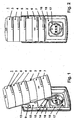
- Fig. 1 is a perspective view of an input device of an installation bus shown with pivoted input element. It is an input device 1 to recognize which has an input element 2 with a total of five tactile sensors 3, 4, 5, 6, 7. These push-button sensors 3 - 7 are used to actuate micro-switches, which correspond Sending signals to an installation bus (eg EIB or network bus).
- an installation bus eg EIB or network bus.
- Each push button sensor 3 - 7 preferably has a labeling field 8 and a function display (LED).
- the input element 2 is a total of four pivot lever (two upper pivot lever and two lower pivoting levers) connected to a base unit 15 which under contains a bus coupling other.
- a base unit 15 which under contains a bus coupling other.
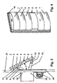
- an upper Swivel lever 9 and a lower pivot lever 10 can be seen.
- the input element 2 with articulation surfaces 11 and 12 (see Fig. 3) provided, each having a joint 13 or 14 (each with joint axis) wear.
- the attachment of each other ends the upper and lower pivoting lever is on the base unit 15 via corresponding Joints 19 and 20 (each with joint axes, see Fig. 3).
- the input element 2 may also be more or less (at least a single) tactile sensors.
- the basic unit is designed flush-mounted and has a cover frame 16 on.
- a socket 17 is installed, wherein between socket 17 and cover 16 a recess 18 is formed is, which in the closed position of the input element 2, the lower pivot lever 10 absorbs.
- FIG. 2 shows a view of an input device 1 with a pivoted input element. Again, there are the touch sensors 3 - 7 of the input device 2, those in the lower Section freely accessible socket 17, the recess 18 for the lower pivot lever and the cover frame 16 to recognize.
- the input device 1 is designed flush-mounted, wherein the base unit 15 engages in a recess (flush-mounted box) of a wall 21 and the cover frame 16 is supported on the wall surface.
- FIG. 4 is a perspective view of an input device 1 with an input element shown in closed position. In this position, the socket 17 completely through the now vertically aligned input element 2 with the tactile sensors 3 - 7 covered.
Landscapes
- Engineering & Computer Science (AREA)
- Architecture (AREA)
- Civil Engineering (AREA)
- Structural Engineering (AREA)
- Switch Cases, Indication, And Locking (AREA)
- Mechanical Control Devices (AREA)
- Position Input By Displaying (AREA)
- Mechanisms For Operating Contacts (AREA)
- Input Circuits Of Receivers And Coupling Of Receivers And Audio Equipment (AREA)
- Devices For Checking Fares Or Tickets At Control Points (AREA)
- Power-Operated Mechanisms For Wings (AREA)
- Selective Calling Equipment (AREA)
Abstract
Description
- Fig.1
- eine perspektivische Sicht auf ein Eingabegerät mit geschwenktem Eingabeelement,
- Fig. 2
- eine Sicht auf ein Eingabegerät mit geschwenktem Eingabeelement,
- Fig. 3
- eine Seitenansicht eines Eingabegerätes mit geschwenktem Eingabeelement,
- Fig. 4
- eine perspektivische Sicht auf ein Eingabegerät mit einem Eingabeelement in geschlossener Position.
- mit oberem Schwenkhebel 9, welcher über Gelenk 13 an der Anlenkfläche 11 des Eingabeelementes 2 sowie über Gelenk 19 am Grundgerät 15 befestigt ist,
- mit unterem Schwenkhebel 10, welcher über Gelenk 14 an der Anlenkfläche 12 des Eingabeelementes 2 sowie über Gelenk 20 am Grundgerät 15 befestigt ist.
- Eine geöffnete Position mit vom Grundgerät 15 nach vorne und oben geschwenktem Eingabeelement 2, wobei in dieser Position eine gute Erkennung von Beschriftungsfeldern der Tastsensoren sowie eine freie Zugänglichkeit der Steckdose 17 gegeben ist.
- Eine geschlossene Position mit vollständiger Abdeckung der Steckdose.
- 1
- Eingabegerät eines Installationsbussystems
- 2
- Schwenkbares Eingabeelement
- 3
- Tastsensor (zur Betätigung von Mikroschaltern)
- 4
- Tastsensor
- 5
- Tastsensor
- 6
- Tastsensor
- 7
- Tastsensor
- 8
- Beschriftungsfeld
- 9
- obere Schwenkhebel
- 10
- untere Schwenkhebel
- 11
- Anlenkfläche
- 12
- Anlenkfläche
- 13
- Gelenk mit Gelenkachse
- 14
- Gelenk mit Gelenkachse
- 15
- Grundgerät mit Busankopplung
- 16
- Abdeckrahmen
- 17
- Steckdose
- 18
- Ausnehmung zur Aufnahme der unteren Schwenkhebel
- 19
- Gelenk mit Gelenkachse
- 20
- Gelenk mit Gelenkachse
- 21
- Wand
- α
- Schwenkwinkel
Claims (9)
- Eingabegerät eines Installationsbussystems mit einem Eingabeelement (2) mit mindestens einem Tastsensor (3, 4, 5, 6, 7), welches mit einem Grundgerät (15) verbunden ist, dadurch gekennzeichnet, dass das Eingabeelement (2) über Schwenkhebel (9, 10) gelenkig mit dem Grundgerät (15) verbunden ist, so dass das Eingabeelement (2) wahlweise in eine geschlossene Position und in eine offene Position mit einem vorgegebenen Schwenkwinkel (α) gegenüber der vertikalen Stellung positionierbar ist.
- Eingabegerät nach Anspruch 1, dadurch gekennzeichnet, dass das Eingabeelement (2) auf jeder Seite mit einem unteren (10) und einem oberen Schwenkhebel (9) mit dem Grundgerät (15) gelenkig verbunden ist.
- Eingabegerät nach Anspruch 1 und/oder 2, dadurch gekennzeichnet, dass am Grundgerät (15) Ausnehmungen (18) zur Aufnahme von Schwenkhebeln (10) vorgesehen sind.
- Eingabegerät nach einem der vorstehenden Ansprüche, dadurch gekennzeichnet, dass im Grundgerät (15) eine Feder zur Bewirkung des Schwenkvorganges integriert ist.
- Eingabegerät nach Anspruch 4, dass die Feder durch Druck auf das Unterteil des Eingabeelementes (2) mechanisch entriegelbar ist.
- Eingabegerät nach Anspruch 5, dadurch gekennzeichnet, dass die Feder durch Betätigung eines Tastsensors (3 - 7) elektrisch entriegelbar ist.
- Eingabegerät nach einem der Ansprüche 1 - 3, dadurch gekennzeichnet, dass im Grundgerät (15) ein Motor zur Bewirkung des Schwenkvorganges integriert ist.
- Eingabegerät nach Anspruch 7, dadurch gekennzeichnet, dass die Initiierung eines Motorstarts durch Betätigung eines Tastsensors (4 - 7) erfolgt.
- Eingabegerät nach einem der vorstehenden Ansprüche, dadurch gekennzeichnet, dass eine Steckdose (17) im unteren Teilabschnitt des Grundgerätes (15) installiert ist.
Applications Claiming Priority (2)
| Application Number | Priority Date | Filing Date | Title |
|---|---|---|---|
| DE102004011643 | 2004-03-10 | ||
| DE102004011643A DE102004011643A1 (de) | 2004-03-10 | 2004-03-10 | Eingabegerät eines Installationsbussystems |
Publications (3)
| Publication Number | Publication Date |
|---|---|
| EP1575070A2 true EP1575070A2 (de) | 2005-09-14 |
| EP1575070A3 EP1575070A3 (de) | 2006-02-22 |
| EP1575070B1 EP1575070B1 (de) | 2008-08-13 |
Family
ID=34813638
Family Applications (1)
| Application Number | Title | Priority Date | Filing Date |
|---|---|---|---|
| EP05003827A Expired - Lifetime EP1575070B1 (de) | 2004-03-10 | 2005-02-23 | Eingabegerät eines Installationsgerätes |
Country Status (5)
| Country | Link |
|---|---|
| EP (1) | EP1575070B1 (de) |
| CN (1) | CN1667774A (de) |
| AT (1) | ATE404985T1 (de) |
| DE (2) | DE102004011643A1 (de) |
| SG (1) | SG115750A1 (de) |
Cited By (2)
| Publication number | Priority date | Publication date | Assignee | Title |
|---|---|---|---|---|
| CH701228A1 (de) * | 2009-06-08 | 2010-12-15 | Feller Ag | Elektrischer Apparat für Hausinstallationen. |
| EP3079209A1 (de) * | 2015-04-09 | 2016-10-12 | TCS TürControlSysteme AG | Befestigungseinrichlung |
Families Citing this family (1)
| Publication number | Priority date | Publication date | Assignee | Title |
|---|---|---|---|---|
| DE102007022340A1 (de) | 2007-05-12 | 2009-01-15 | Abb Ag | Sensoreinheit |
Family Cites Families (6)
| Publication number | Priority date | Publication date | Assignee | Title |
|---|---|---|---|---|
| US5351066A (en) * | 1991-07-08 | 1994-09-27 | Ergologic Enterprises Inc. | Rotating plane keyboard |
| GB2285014A (en) * | 1993-12-23 | 1995-06-28 | Silitek Corp | Keyboard with tilt adjustment. |
| DE4418255C2 (de) * | 1994-05-25 | 1997-12-18 | Maren Lange | Fernbedienung und Fernanzeige |
| US5732928A (en) * | 1996-03-26 | 1998-03-31 | Behavior Tech Computer Corporation | Computer keyboard stand |
| DE19737907B4 (de) * | 1997-09-01 | 2007-10-18 | Abb Patent Gmbh | Tastschalteranordnung |
| US6579022B1 (en) * | 2000-03-09 | 2003-06-17 | Active Input Solutions, Llc | Keyboard support platform |
-
2004
- 2004-03-10 DE DE102004011643A patent/DE102004011643A1/de not_active Ceased
-
2005
- 2005-02-23 DE DE502005004983T patent/DE502005004983D1/de not_active Expired - Lifetime
- 2005-02-23 EP EP05003827A patent/EP1575070B1/de not_active Expired - Lifetime
- 2005-02-23 AT AT05003827T patent/ATE404985T1/de not_active IP Right Cessation
- 2005-03-09 SG SG200501484A patent/SG115750A1/en unknown
- 2005-03-09 CN CN200510054383.1A patent/CN1667774A/zh active Pending
Cited By (2)
| Publication number | Priority date | Publication date | Assignee | Title |
|---|---|---|---|---|
| CH701228A1 (de) * | 2009-06-08 | 2010-12-15 | Feller Ag | Elektrischer Apparat für Hausinstallationen. |
| EP3079209A1 (de) * | 2015-04-09 | 2016-10-12 | TCS TürControlSysteme AG | Befestigungseinrichlung |
Also Published As
| Publication number | Publication date |
|---|---|
| SG115750A1 (en) | 2005-10-28 |
| CN1667774A (zh) | 2005-09-14 |
| DE502005004983D1 (de) | 2008-09-25 |
| DE102004011643A1 (de) | 2005-10-27 |
| EP1575070A3 (de) | 2006-02-22 |
| ATE404985T1 (de) | 2008-08-15 |
| EP1575070B1 (de) | 2008-08-13 |
Similar Documents
| Publication | Publication Date | Title |
|---|---|---|
| DE10051171B4 (de) | Wippschalter | |
| DE69607430T2 (de) | Deckel für eine elektrische Verbindungsanordnung | |
| DE102004019627B4 (de) | Fahrzeugtürgriffvorrichtung | |
| DE10159647B4 (de) | Innenraum-Beleuchtungssystem für Fahrzeuge | |
| EP1993180B1 (de) | Sensoreinheit zur Montage in einer Installationsdose | |
| DE102012105020B4 (de) | Schalter für einen elektrischen Fensterheber | |
| DE112010004592T5 (de) | Verbinder und Verbindungsstruktur für einen Fahrzeugkabelbaum | |
| DE102023110987B3 (de) | Funktionsmodul, Anordnung umfassend ein solches und ein Schaltgerät sowie Verfahren zur Montage | |
| WO1999030928A1 (de) | Mehrfunktionsschalter | |
| DE102006024994B3 (de) | Elektronischer Schalter | |
| EP2633537B1 (de) | Schlüsselkartenschalter | |
| DE102019209521B4 (de) | Benutzerschnittstelleneinheit | |
| EP0762449B1 (de) | Wipptaster | |
| EP1575070B1 (de) | Eingabegerät eines Installationsgerätes | |
| DE3835073C2 (de) | Elektrischer Schalter für eine Kraftfahrzeug-Fensterhebevorrichtung | |
| EP2696359B1 (de) | Elektrischer schalter und verfahren zum montieren einer schalteinheit eines elektrischen schalters | |
| DE102012101789A1 (de) | Umschalteinrichtung | |
| DE102012106095A1 (de) | Schalter | |
| DE10110303A1 (de) | Verschließbarer Flügel für ein Kraftfahrzeug | |
| DE3538847A1 (de) | Schalterblock | |
| EP1102291A2 (de) | Elektrischer Installationsschalter sowie Bauteilsystem und Glimmlampe für einen elektrischen Installationsschalter | |
| EP3575528B1 (de) | Innenausbauvorrichtung | |
| WO2004050404A2 (de) | Kraftfahrzeugtür | |
| DE29909467U1 (de) | Stromschiene | |
| DE60207865T2 (de) | Elektrische Steckerverbinderanordnung für Flachbandkabel |
Legal Events
| Date | Code | Title | Description |
|---|---|---|---|
| PUAI | Public reference made under article 153(3) epc to a published international application that has entered the european phase |
Free format text: ORIGINAL CODE: 0009012 |
|
| AK | Designated contracting states |
Kind code of ref document: A2 Designated state(s): AT BE BG CH CY CZ DE DK EE ES FI FR GB GR HU IE IS IT LI LT LU MC NL PL PT RO SE SI SK TR |
|
| AX | Request for extension of the european patent |
Extension state: AL BA HR LV MK YU |
|
| PUAL | Search report despatched |
Free format text: ORIGINAL CODE: 0009013 |
|
| AK | Designated contracting states |
Kind code of ref document: A3 Designated state(s): AT BE BG CH CY CZ DE DK EE ES FI FR GB GR HU IE IS IT LI LT LU MC NL PL PT RO SE SI SK TR |
|
| AX | Request for extension of the european patent |
Extension state: AL BA HR LV MK YU |
|
| RIC1 | Information provided on ipc code assigned before grant |
Ipc: H01H 13/70 20060101AFI20050719BHEP Ipc: H02G 3/08 20060101ALI20060105BHEP |
|
| AKX | Designation fees paid |
Designated state(s): AT BE CH DE LI NL |
|
| 17P | Request for examination filed |
Effective date: 20061005 |
|
| 17Q | First examination report despatched |
Effective date: 20070417 |
|
| GRAP | Despatch of communication of intention to grant a patent |
Free format text: ORIGINAL CODE: EPIDOSNIGR1 |
|
| RAP1 | Party data changed (applicant data changed or rights of an application transferred) |
Owner name: ABB AG |
|
| GRAS | Grant fee paid |
Free format text: ORIGINAL CODE: EPIDOSNIGR3 |
|
| GRAA | (expected) grant |
Free format text: ORIGINAL CODE: 0009210 |
|
| AK | Designated contracting states |
Kind code of ref document: B1 Designated state(s): AT BE CH DE LI NL |
|
| REG | Reference to a national code |
Ref country code: CH Ref legal event code: EP |
|
| REF | Corresponds to: |
Ref document number: 502005004983 Country of ref document: DE Date of ref document: 20080925 Kind code of ref document: P |
|
| PG25 | Lapsed in a contracting state [announced via postgrant information from national office to epo] |
Ref country code: NL Free format text: LAPSE BECAUSE OF FAILURE TO SUBMIT A TRANSLATION OF THE DESCRIPTION OR TO PAY THE FEE WITHIN THE PRESCRIBED TIME-LIMIT Effective date: 20080813 |
|
| PLBE | No opposition filed within time limit |
Free format text: ORIGINAL CODE: 0009261 |
|
| STAA | Information on the status of an ep patent application or granted ep patent |
Free format text: STATUS: NO OPPOSITION FILED WITHIN TIME LIMIT |
|
| 26N | No opposition filed |
Effective date: 20090514 |
|
| BERE | Be: lapsed |
Owner name: ABB A.G. Effective date: 20090228 |
|
| REG | Reference to a national code |
Ref country code: CH Ref legal event code: PL |
|
| PG25 | Lapsed in a contracting state [announced via postgrant information from national office to epo] |
Ref country code: CH Free format text: LAPSE BECAUSE OF NON-PAYMENT OF DUE FEES Effective date: 20090228 Ref country code: LI Free format text: LAPSE BECAUSE OF NON-PAYMENT OF DUE FEES Effective date: 20090228 |
|
| PG25 | Lapsed in a contracting state [announced via postgrant information from national office to epo] |
Ref country code: BE Free format text: LAPSE BECAUSE OF NON-PAYMENT OF DUE FEES Effective date: 20090228 |
|
| PG25 | Lapsed in a contracting state [announced via postgrant information from national office to epo] |
Ref country code: AT Free format text: LAPSE BECAUSE OF NON-PAYMENT OF DUE FEES Effective date: 20090223 |
|
| PGFP | Annual fee paid to national office [announced via postgrant information from national office to epo] |
Ref country code: DE Payment date: 20170217 Year of fee payment: 13 |
|
| REG | Reference to a national code |
Ref country code: DE Ref legal event code: R119 Ref document number: 502005004983 Country of ref document: DE |
|
| PG25 | Lapsed in a contracting state [announced via postgrant information from national office to epo] |
Ref country code: DE Free format text: LAPSE BECAUSE OF NON-PAYMENT OF DUE FEES Effective date: 20180901 |