EP1574707B1 - Leerlaufdrehzahlregelvorrichtung für Kraftfahrzeugmotor - Google Patents
Leerlaufdrehzahlregelvorrichtung für Kraftfahrzeugmotor Download PDFInfo
- Publication number
- EP1574707B1 EP1574707B1 EP05002283A EP05002283A EP1574707B1 EP 1574707 B1 EP1574707 B1 EP 1574707B1 EP 05002283 A EP05002283 A EP 05002283A EP 05002283 A EP05002283 A EP 05002283A EP 1574707 B1 EP1574707 B1 EP 1574707B1
- Authority
- EP
- European Patent Office
- Prior art keywords
- idle speed
- target idle
- ignition timing
- traveling
- engine
- Prior art date
- Legal status (The legal status is an assumption and is not a legal conclusion. Google has not performed a legal analysis and makes no representation as to the accuracy of the status listed.)
- Ceased
Links
- 230000005540 biological transmission Effects 0.000 claims description 62
- 239000012530 fluid Substances 0.000 claims description 16
- 230000008859 change Effects 0.000 claims description 12
- 230000007423 decrease Effects 0.000 claims description 9
- 238000013459 approach Methods 0.000 claims description 4
- 230000035939 shock Effects 0.000 description 23
- 239000000446 fuel Substances 0.000 description 19
- 239000003921 oil Substances 0.000 description 18
- 238000002485 combustion reaction Methods 0.000 description 15
- 230000006870 function Effects 0.000 description 12
- 230000003197 catalytic effect Effects 0.000 description 9
- 238000002347 injection Methods 0.000 description 8
- 239000007924 injection Substances 0.000 description 8
- 239000002826 coolant Substances 0.000 description 7
- 230000002441 reversible effect Effects 0.000 description 6
- 230000004913 activation Effects 0.000 description 4
- 238000000034 method Methods 0.000 description 4
- 239000000203 mixture Substances 0.000 description 4
- 230000015556 catabolic process Effects 0.000 description 3
- 230000003247 decreasing effect Effects 0.000 description 3
- 238000006731 degradation reaction Methods 0.000 description 3
- 238000010586 diagram Methods 0.000 description 3
- 230000004044 response Effects 0.000 description 3
- 239000003054 catalyst Substances 0.000 description 2
- 238000010438 heat treatment Methods 0.000 description 2
- 239000010705 motor oil Substances 0.000 description 2
- 230000000979 retarding effect Effects 0.000 description 2
- 230000003213 activating effect Effects 0.000 description 1
- 239000010718 automatic transmission oil Substances 0.000 description 1
- 238000004140 cleaning Methods 0.000 description 1
- 238000004891 communication Methods 0.000 description 1
- 230000003111 delayed effect Effects 0.000 description 1
- 230000001419 dependent effect Effects 0.000 description 1
- 238000013461 design Methods 0.000 description 1
- 238000001514 detection method Methods 0.000 description 1
- 238000005516 engineering process Methods 0.000 description 1
- 230000006698 induction Effects 0.000 description 1
- 230000004941 influx Effects 0.000 description 1
- 239000003112 inhibitor Substances 0.000 description 1
- 230000007935 neutral effect Effects 0.000 description 1
- 230000002093 peripheral effect Effects 0.000 description 1
- 238000012545 processing Methods 0.000 description 1
- 238000000746 purification Methods 0.000 description 1
Images


Classifications
-
- F—MECHANICAL ENGINEERING; LIGHTING; HEATING; WEAPONS; BLASTING
- F02—COMBUSTION ENGINES; HOT-GAS OR COMBUSTION-PRODUCT ENGINE PLANTS
- F02P—IGNITION, OTHER THAN COMPRESSION IGNITION, FOR INTERNAL-COMBUSTION ENGINES; TESTING OF IGNITION TIMING IN COMPRESSION-IGNITION ENGINES
- F02P5/00—Advancing or retarding ignition; Control therefor
- F02P5/04—Advancing or retarding ignition; Control therefor automatically, as a function of the working conditions of the engine or vehicle or of the atmospheric conditions
- F02P5/145—Advancing or retarding ignition; Control therefor automatically, as a function of the working conditions of the engine or vehicle or of the atmospheric conditions using electrical means
- F02P5/15—Digital data processing
- F02P5/1502—Digital data processing using one central computing unit
- F02P5/1506—Digital data processing using one central computing unit with particular means during starting
-
- F—MECHANICAL ENGINEERING; LIGHTING; HEATING; WEAPONS; BLASTING
- F02—COMBUSTION ENGINES; HOT-GAS OR COMBUSTION-PRODUCT ENGINE PLANTS
- F02D—CONTROLLING COMBUSTION ENGINES
- F02D41/00—Electrical control of supply of combustible mixture or its constituents
- F02D41/02—Circuit arrangements for generating control signals
- F02D41/021—Introducing corrections for particular conditions exterior to the engine
- F02D41/0215—Introducing corrections for particular conditions exterior to the engine in relation with elements of the transmission
- F02D41/023—Introducing corrections for particular conditions exterior to the engine in relation with elements of the transmission in relation with the gear ratio shifting
-
- F—MECHANICAL ENGINEERING; LIGHTING; HEATING; WEAPONS; BLASTING
- F02—COMBUSTION ENGINES; HOT-GAS OR COMBUSTION-PRODUCT ENGINE PLANTS
- F02D—CONTROLLING COMBUSTION ENGINES
- F02D41/00—Electrical control of supply of combustible mixture or its constituents
- F02D41/02—Circuit arrangements for generating control signals
- F02D41/021—Introducing corrections for particular conditions exterior to the engine
- F02D41/0235—Introducing corrections for particular conditions exterior to the engine in relation with the state of the exhaust gas treating apparatus
- F02D41/024—Introducing corrections for particular conditions exterior to the engine in relation with the state of the exhaust gas treating apparatus to increase temperature of the exhaust gas treating apparatus
- F02D41/0255—Introducing corrections for particular conditions exterior to the engine in relation with the state of the exhaust gas treating apparatus to increase temperature of the exhaust gas treating apparatus to accelerate the warming-up of the exhaust gas treating apparatus at engine start
-
- F—MECHANICAL ENGINEERING; LIGHTING; HEATING; WEAPONS; BLASTING
- F02—COMBUSTION ENGINES; HOT-GAS OR COMBUSTION-PRODUCT ENGINE PLANTS
- F02D—CONTROLLING COMBUSTION ENGINES
- F02D41/00—Electrical control of supply of combustible mixture or its constituents
- F02D41/02—Circuit arrangements for generating control signals
- F02D41/04—Introducing corrections for particular operating conditions
- F02D41/08—Introducing corrections for particular operating conditions for idling
- F02D41/083—Introducing corrections for particular operating conditions for idling taking into account engine load variation, e.g. air-conditionning
-
- F—MECHANICAL ENGINEERING; LIGHTING; HEATING; WEAPONS; BLASTING
- F02—COMBUSTION ENGINES; HOT-GAS OR COMBUSTION-PRODUCT ENGINE PLANTS
- F02P—IGNITION, OTHER THAN COMPRESSION IGNITION, FOR INTERNAL-COMBUSTION ENGINES; TESTING OF IGNITION TIMING IN COMPRESSION-IGNITION ENGINES
- F02P5/00—Advancing or retarding ignition; Control therefor
- F02P5/04—Advancing or retarding ignition; Control therefor automatically, as a function of the working conditions of the engine or vehicle or of the atmospheric conditions
- F02P5/145—Advancing or retarding ignition; Control therefor automatically, as a function of the working conditions of the engine or vehicle or of the atmospheric conditions using electrical means
- F02P5/15—Digital data processing
- F02P5/1502—Digital data processing using one central computing unit
- F02P5/1504—Digital data processing using one central computing unit with particular means during a transient phase, e.g. acceleration, deceleration, gear change
-
- F—MECHANICAL ENGINEERING; LIGHTING; HEATING; WEAPONS; BLASTING
- F02—COMBUSTION ENGINES; HOT-GAS OR COMBUSTION-PRODUCT ENGINE PLANTS
- F02P—IGNITION, OTHER THAN COMPRESSION IGNITION, FOR INTERNAL-COMBUSTION ENGINES; TESTING OF IGNITION TIMING IN COMPRESSION-IGNITION ENGINES
- F02P5/00—Advancing or retarding ignition; Control therefor
- F02P5/04—Advancing or retarding ignition; Control therefor automatically, as a function of the working conditions of the engine or vehicle or of the atmospheric conditions
- F02P5/145—Advancing or retarding ignition; Control therefor automatically, as a function of the working conditions of the engine or vehicle or of the atmospheric conditions using electrical means
- F02P5/15—Digital data processing
- F02P5/1502—Digital data processing using one central computing unit
- F02P5/1508—Digital data processing using one central computing unit with particular means during idling
-
- B—PERFORMING OPERATIONS; TRANSPORTING
- B60—VEHICLES IN GENERAL
- B60W—CONJOINT CONTROL OF VEHICLE SUB-UNITS OF DIFFERENT TYPE OR DIFFERENT FUNCTION; CONTROL SYSTEMS SPECIALLY ADAPTED FOR HYBRID VEHICLES; ROAD VEHICLE DRIVE CONTROL SYSTEMS FOR PURPOSES NOT RELATED TO THE CONTROL OF A PARTICULAR SUB-UNIT
- B60W2710/00—Output or target parameters relating to a particular sub-units
- B60W2710/06—Combustion engines, Gas turbines
- B60W2710/0644—Engine speed
- B60W2710/065—Idle condition
-
- F—MECHANICAL ENGINEERING; LIGHTING; HEATING; WEAPONS; BLASTING
- F02—COMBUSTION ENGINES; HOT-GAS OR COMBUSTION-PRODUCT ENGINE PLANTS
- F02D—CONTROLLING COMBUSTION ENGINES
- F02D41/00—Electrical control of supply of combustible mixture or its constituents
- F02D41/02—Circuit arrangements for generating control signals
- F02D41/021—Introducing corrections for particular conditions exterior to the engine
- F02D41/0215—Introducing corrections for particular conditions exterior to the engine in relation with elements of the transmission
- F02D41/022—Introducing corrections for particular conditions exterior to the engine in relation with elements of the transmission in relation with the clutch status
-
- F—MECHANICAL ENGINEERING; LIGHTING; HEATING; WEAPONS; BLASTING
- F16—ENGINEERING ELEMENTS AND UNITS; GENERAL MEASURES FOR PRODUCING AND MAINTAINING EFFECTIVE FUNCTIONING OF MACHINES OR INSTALLATIONS; THERMAL INSULATION IN GENERAL
- F16H—GEARING
- F16H61/00—Control functions within control units of change-speed- or reversing-gearings for conveying rotary motion ; Control of exclusively fluid gearing, friction gearing, gearings with endless flexible members or other particular types of gearing
- F16H61/04—Smoothing ratio shift
- F16H2061/0488—Smoothing ratio shift during range shift from neutral (N) to drive (D)
-
- Y—GENERAL TAGGING OF NEW TECHNOLOGICAL DEVELOPMENTS; GENERAL TAGGING OF CROSS-SECTIONAL TECHNOLOGIES SPANNING OVER SEVERAL SECTIONS OF THE IPC; TECHNICAL SUBJECTS COVERED BY FORMER USPC CROSS-REFERENCE ART COLLECTIONS [XRACs] AND DIGESTS
- Y02—TECHNOLOGIES OR APPLICATIONS FOR MITIGATION OR ADAPTATION AGAINST CLIMATE CHANGE
- Y02T—CLIMATE CHANGE MITIGATION TECHNOLOGIES RELATED TO TRANSPORTATION
- Y02T10/00—Road transport of goods or passengers
- Y02T10/10—Internal combustion engine [ICE] based vehicles
- Y02T10/12—Improving ICE efficiencies
-
- Y—GENERAL TAGGING OF NEW TECHNOLOGICAL DEVELOPMENTS; GENERAL TAGGING OF CROSS-SECTIONAL TECHNOLOGIES SPANNING OVER SEVERAL SECTIONS OF THE IPC; TECHNICAL SUBJECTS COVERED BY FORMER USPC CROSS-REFERENCE ART COLLECTIONS [XRACs] AND DIGESTS
- Y02—TECHNOLOGIES OR APPLICATIONS FOR MITIGATION OR ADAPTATION AGAINST CLIMATE CHANGE
- Y02T—CLIMATE CHANGE MITIGATION TECHNOLOGIES RELATED TO TRANSPORTATION
- Y02T10/00—Road transport of goods or passengers
- Y02T10/10—Internal combustion engine [ICE] based vehicles
- Y02T10/40—Engine management systems
Definitions
- the present invention relates to an engine idle speed control device according to the preamble of independent claim 1.
- Such an engine idle speed control device can be taken from the prior art document US 2002/0124554 A1.
- a catalyst is warmed up by a rapid heating control that retards ignition timing and increases an intake air amount. Then the warm up is completed or a transmission is shifted to a drive range, the ignition timing is gradually advanced and the intake air amount is gradually decreased. Therefore, an engine speed is smoothly changed from the rapid heating control to the normal control without a torque shock.
- a beginning of the advancing of the ignition timing is delayed by a predetermined delay time relative to a beginning of the decreasing of the intake air amount. The decreasing of the intake air amount prevents undesirable increase of the engine speed caused by the advancing of the ignition timing.
- Japanese Laid-Open Patent Publication No. 05-280398 discloses a technology regarding an engine provided with an automatic transmission in which the actual engine speed is adjusted toward a target idle speed based on the difference between the actual engine speed and the target idle speed by feedback controlling the air quantity.
- the engine is configured such that when the automatic transmission is shifted from a non-traveling range (e.g., the N range) to a traveling range (e.g., the D range), the target idle speed is lowered in two stages.
- the target idle speed is changed from the target idle speed for the non-traveling range to a first traveling target idle speed for the traveling range that is lower than the target idle speed for the non-traveling range. Then, when a prescribed period has elapsed since the shift position of the automatic transmission was changed, the target idle speed is changed from the first traveling target idle speed for the traveling range to a second traveling target idle speed that is lower than the first traveling target idle speed.
- the first traveling target idle speed is a rotational speed at which the clutch engagement shock would be at a tolerable level, but in order to avoid the clutch engagement shock it is necessary for the engine speed to fall to the first traveling target idle speed during the short amount of time between when the shift position is changed and when the clutch actually connects.
- the response speed is slow and it is difficult to ramp down to the first traveling target idle speed within the short amount of time. Consequently, this approach to controlling the idle speed does not completely solve the problem of clutch engagement shock because there are times when the rotational speed of the engine does not fall sufficiently before the clutch engages.
- an engine idle speed control device that can accomplish the following when the automatic transmission is shifted from a non-traveling range to a traveling range: reduce the engine speed to a first traveling target idle speed in a short amount of time without causing an abrupt change in torque due to reduced rotational speed and without causing the occurrence of clutch engagement shock.
- an engine idle speed control device that basically comprise a first traveling target idle speed setting section, a second idle speed setting section and an ignition timing retardation section.
- the first traveling target idle speed setting section is configured to change a target idle speed from a non-traveling target idle speed to a first traveling target idle speed that is lower than the non-traveling target idle speed upon detecting an automatic transmission being shifted from a non-traveling range to a traveling range.
- the second idle speed setting section is configured to change the first traveling target idle speed to a second traveling target idle speed that is lower than the first traveling target idle speed upon detecting a prescribed period has elapsed since detecting that the automatic transmission was shifted.
- the ignition timing retardation section is configured to selectively set a retardation amount of an ignition timing based on an actual engine rotational speed when the first traveling target idle speed has been set, with the retardation amount being set such that as the engine rotational speed becomes higher, the ignition timing is set to be more retarded.
- Figure 1 is a simplified schematic illustration of an engine equipped with an engine idle speed control device or system in accordance with a first embodiment of the present teaching ;
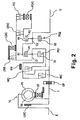
- FIG. 2 is a simplified schematic diagram of an automatic transmission used with engines in accordance with the various embodiments of the present teaching ;
- Figure 3 is a table that shows the operating states of the friction elements of the automatic transmission in accordance with the various embodiments of the present teaching ;
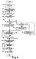
- FIG. 4 is a flowchart of a target idle speed setting routine in accordance with the first embodiment of the present teaching ;
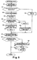
- FIG. 5 is a flowchart of an ignition timing control routine in accordance with the first embodiment of the present teaching ;
- Figure 6 is a table for setting the ignition timing retardation amount in accordance with the first embodiment of the present teaching ;
- Figure 7 are time charts showing the control of the engine rotational speed executed after the engine is started relative to various settings in accordance with the first embodiment of the present teaching ;
- Figure 8 is a flowchart of a target idle speed setting routine in accordance with a second embodiment of the present teaching .
- Figure 9 are time charts showing the relationship between the engine rotational speed executed after the engine is started relative to low and high transmission fluid temperatures in accordance with the second embodiment of the present teaching .
- an internal combustion engine 1 with an output shaft E of the engine 1 connected to an automatic transmission 10 is diagrammatically illustrated in accordance with a first embodiment of the present invention.
- the engine 1 is equipped with various components that constitute an engine idle speed control device or system in accordance with a first embodiment of the present invention.
- the engine 1 has an air intake passage 2 with an electronically controlled throttle valve 3 mounted therein.
- the electronically controlled throttle valve 3 is configured and arranged for controlling the intake air quantity to the air intake passage 2 of the engine 1 by way of one or more intake valves 4 (only one shown).
- the air intake passage 2 is fluidly connected to a plurality of combustion chambers 5 (only one shown) of the engine 1.
- Each combustion chamber 5 includes a spark plug 6 and a fuel injection valve 7.
- the spark plug 6 and the fuel injection valve 7 are mounted to the combustion chamber 5 in a conventional manner.
- the engine 1 is controlled by an engine control unit (ECU) 20 that is configured and arranged to serve as an engine controller.
- the engine control unit forms a part of the engine idle speed control device that is configured and arranged to reduce the clutch engagement shock that occurs when an automatic transmission is shifted from a non-traveling range to a traveling range after starting the engine 1 of a vehicle by controlling the idle speed of the engine 1 in an exact manner.
- the opening degree of the electronically controlled throttle valve 3 is controlled by a stepper motor or the like that is operated with a signal from the engine control unit 20.
- the fuel injection valve 7 has a solenoid and is configured to open when the solenoid is energized by an injection pulse signal that is issued from the engine control unit 20 in synchronization with the engine rotation. When the fuel injection valve 7 opens, it injects fuel that has been pressurized to a prescribed pressure.
- the fuel forms an air-fuel mixture and is combusted by a spark from the spark plug 6.
- the spark plug 6 ignites a spark based on an ignition signal issued from the engine control unit 20.
- the fuel is injected directly into the combustion chamber 5, it is also acceptable for the fuel to be injected into the air induction system.
- the fuel injected in the combustion chamber 5 forms an air-fuel mixture, that is ignited and combusted by a spark from the spark plug 6.
- the engine 1 also has one or more exhaust valves 13 arranged in each of the combustion chambers 5 with the exhaust ports being fluidly connected to an exhaust passage 14.
- the exhaust passage 14 includes a catalytic converter 15 with a catalyst for exhaust purification in a conventional manner.
- the air-fuel mixture after being combusted results in exhaust being expelled to the exhaust passage 14 by way of the exhaust valve(s) 13.
- the exhaust is then fed to the catalytic converter 15 for cleaning the exhaust.
- the engine 1 is controlled by an engine control unit or engine control unit 20 to perform the controlled combustion of the fuel air mixture as discussed below.
- the amount of retardation of the ignition timing is set by the engine control unit 20 in accordance with the actual engine rotational speed and is set such that the higher the engine rotational speed is, the more the ignition timing is retarded.
- the higher the engine speed is when the transmission is in the non-traveling range the larger the amount by which the engine speed is reduced when the transmission is shifted to the traveling range.
- the engine speed can be reliably reduced to the first traveling target idle speed in short amount of time and clutch engagement shock can be prevented. This result enables the target idle speed used in the non-traveling range to be set high in order to promote early activation of the catalytic converter 15.
- the engine control unit 20 is a microcomputer comprising of a central processing unit (CPU) and other peripheral devices.
- the engine control unit 20 can also include other conventional components such as an input interface circuit, an output interface circuit, and storage devices such as a ROM (Read Only Memory) device and a RAM (Random Access Memory) device.
- the engine control unit 20 preferably includes an engine control program that controls various components as discussed below.
- the engine control unit 20 receives input signals from various sensors (described below) that serve to detect the operating state of the engine 1 and executes the engine controls based on these signals. It will be apparent to those skilled in the art from this disclosure that the precise structure and algorithms for the engine control unit 20 can be any combination of hardware and software that will carry out the functions of the present teaching invention.
- "means plus function" clauses as utilized in the specification and claims should include any structure or hardware and/or algorithm or software that can be utilized to carry out the function of the "means plus function” clause.
- the engine control unit 20 receives the following as input signals: the accelerator position APO detected by an accelerator pedal sensor 21, the engine rotational speed Ne detected by a crank angle sensor 22, the intake air quantity Qa detected by a hot wire air flow meter 23, the throttle valve opening TVO detected by a throttle sensor 24, an engine coolant temperature Tw detected by a coolant temperature sensor 25 and the engine oil temperature Teng-Oil detected by an oil temperature sensor 26 and like.
- Examples of signals input to the engine control unit 20 include the accelerator position APO detected by an accelerator pedal sensor 21, the engine rotational speed Ne detected by a crank angle sensor 22, the intake air quantity Qa detected by an air flow meter 23, and the engine coolant temperature Tw detected by a coolant temperature sensor 24. Signals are also input from the engine key switch 26 having an ignition switch and a start switch.
- the engine control unit 20 controls the opening degree of the electronically control throttle valve 3, the fuel injection timing and fuel injection quantity of the fuel injection valve 7 5, and the ignition timing of the spark plug 6 based on the engine operating conditions indicated by the input signals.
- the engine control unit 20 detects the actual engine rotational speed Ne and, based on the difference between the actual engine rotational speed Ne and a target idle speed, controls the opening degree of the throttle valve 3 and feedback controls the air quantity such that the actual engine rotational speed Ne approaches the target idle speed. Additionally, in consideration of the response delay of the air quantity control, the ignition timing is feedback controlled based on the difference between the actual engine rotational speed Ne and the target idle speed such that the actual engine rotational speed Ne approaches the target idle speed.
- the output shaft E of the engine 1 is operatively connected to an automatic transmission 10 as illustrated in Figure 2, which is a simplified schematic diagram of the automatic transmission 10.
- the automatic transmission 10 basically includes an input shaft I, a torque converter TC, a first planetary gear set PC1, a second planetary gear set PC2, an output shaft O, and various friction elements.
- the torque converter TC is configured and arranged to transmit rotation from the engine output shaft E to the input shaft I, which in turn is operatively connected to the output shaft O through the first planetary gear set PC1, the second planetary gear set PC2 and various friction elements.
- the torque converter TC comprises a pump impeller PI, a turbine runner TR, and a stator ST.
- the pump impeller PI is configured and arranged to be driven by the engine output shaft E.
- the turbine runner TR is arranged and configured to be fluid-driven by the pump impeller PI through an internal working fluid and transmit power to the input shaft I.
- the stator ST is mounted on a stationary shaft with a one-way clutch disposed there-between.
- the stator ST is configured to increase the torque imparted to the turbine runner TR.
- the torque converter TC is also equipped with a lockup clutch LU/C that can establish a direction connection between the engine output shaft E and the input shaft I.
- the first planetary gear set PG1 comprises a sun gear S1, a ring gear R1, a pinion P1 and a carrier C1.
- the pinion P1 that meshes with the sun gear S 1 and the ring gear R1, while the carrier C1 supports the pinion P1 in a freely rotatable manner.
- the second planetary gear set PG2 comprises a sun gear S2, a ring gear R2, a pinion P2, and a carrier C2.
- the pinion P2 that meshes with the sun gear S2 and the ring gear R2, while the carrier C2 supports the pinion P2 in a freely rotatable manner.
- the carrier C1 is configured and arranged such that it can be selectively connected to the input shaft I through a high clutch H/C when appropriate.
- the sun gear S 1 is configured and arranged such that it can be selectively held stationary when appropriate by a band brake B/B and connected to the input shaft I when appropriate by a reverse clutch R/C.
- the carrier C 1 can also be selectively held stationary when appropriate by a low reverse brake LR/B and prevented from rotating backwards (opposite direction as engine output shaft) by a low one-way clutch LO/C.
- the ring gear R1 is integrally connected to the carrier C2 such that it drives the output shaft O, while the sun gear S2 is connected to the input shaft I.
- the ring gear R2 can be selectively connected to the carrier C1 when appropriate by an overrun clutch OR/C and its relationship to the carrier C1 can also be modified by a forward one-way clutch FO/C and a forward clutch F/C.
- the high clutch H/C, the reverse clutch R/C, the low reverse brake LR/B, the overrun clutch OR/C, the forward clutch F/C, and the band brake B/B are each hydraulically operated such that they can be connected or held stationary as appropriate.
- an oil pump OP is provided on the input shaft I of the transmission and is configured and arranged to pump out oil when the input shaft I rotates. Since the oil discharged from oil pump OP controls the clutches, when the rotational speed of the input shaft I increases, the output of the oil pump OP increases and the shift lag shortens.
- the automatic transmission shown in Figure 2 is thus configured such that by operating different combinations of the friction elements B/B, H/C, F/C, OR/C, LR/B, R/C as shown in Figure 3 together with appropriate operation of the friction elements FO/C and LO/C, the rotational states of the component elements of the planetary gear sets PG1, PG2 can be changed. As a result, the rotational speed of the output shaft O with respect to the rotational speed of the input shaft I can be changed so as to obtain four forward speeds and one reverse speed, as shown in Figure 3.
- circles (o) indicate operation of (influx of working fluid to) the element and triangles ( ⁇ ) indicate friction elements that should be operated when engine braking is necessary.
- the friction elements of the automatic transmission 10 are controlled by an automatic transmission control unit (ATCU) 30.
- the automatic transmission control unit 30 receives input signals from a shift position sensor (inhibitor switch) 31, a vehicle speed sensor 32 and an AT oil temperature sensor 33.
- the shift position sensor 31 is configured and arranged to detect the shift position (e.g., neutral N, drive D, reverse R) of a shift selector and output a signal indicative of the shift position to the automatic transmission control unit 30.
- the vehicle speed sensor 32 is configured and arranged to detect the vehicle speed VSP and output a signal indicative of the vehicle speed to the automatic transmission control unit 30.
- the AT oil temperature sensor 33 is configured and arranged to detect the oil temperature (AT oil temperature) Tat-oil and like of the transmission 10 and output a signal indicative of the oil temperature to the automatic transmission control unit 30.
- the engine control unit 20 and the automatic transmission control unit 30 are connected together by a communication line 34 so that they can exchange information.
- the automatic transmission control unit 30 sets the gear ratio (first, second, third, or fourth speed) of the automatic transmission 10 based on the shift position detected by the shift position sensor 31 and, in the case of the D range, based on the accelerator position APO and the vehicle speed VSP. The automatic transmission control unit 30 then controls the friction elements of the automatic transmission 10 as appropriate.
- the engine control unit 20 takes the shift position information and/or and the AT oil temperature Tat-oil obtained from the automatic transmission control unit 30 into account when it controls the idle speed (i.e., sets the target idle speed, etc.).
- Figure 4 is a flowchart for a target idle speed setting routine executed by the engine control unit 20 after the engine is started.
- the routine also serves to select the method of setting the ignition timing.
- step S1 as an initial setting, the engine control unit 20 sets the target idle speed Nset to a target idle speed NsetN for the N range.
- the target idle speed NsetN for the N range is set to a high speed in order to accomplish early activation of the catalytic converter after a cold start.
- the target idle speed NsetN can also be varied (e.g., between 1200 and 2500 rpm) depending on the coolant temperature Tw when the engine 1 is started and the amount of time that has elapsed since the engine 1 was started.
- step S2 the engine control unit 20 selects the normal method of setting the ignition timing.
- the ignition timing is feedback controlled based on the difference between the actual engine rotational speed Ne and the target idle speed Nset.
- step S3 the engine control unit 20 determines if the shift position has been changed from a non-traveling range (e.g., the N range) to a traveling range (e.g., the D range), i.e., if the shift selector has been moved from, for example, N to D, based on the signal from the shift position sensor 31. If so, the engine control unit 20 proceeds to step S4.
- a non-traveling range e.g., the N range
- a traveling range e.g., the D range
- step S4 since the shift selector has been moved from N to D, the engine control unit 20 changes the target idle speed Nset to a first traveling target idle speed Nset1 for the D range.
- the first traveling target idle speed Nset1 for the D range is set to a lower value than the target idle speed NsetN for the N range, i.e., to a value (e.g., 1000 rpm) at which an abrupt torque change will not occur due to the decline in rotational speed with respect to the target idle speed NsetN for the N range and clutch engagement shock will not occur.
- step S5 the engine control unit 20 detects the actual engine rotational speed Ne and determines if it is equal to or higher than a first threshold value Nlmt1 (e.g., 1500 rpm). If the engine rotational speed Ne is less than the first threshold value Nlmt1, the engine control unit 20 proceeds to step S6 where it selects normal setting of the ignition timing.
- a first threshold value Nlmt1 e.g. 1500 rpm
- step S7 If the engine rotational speed Ne is equal to or higher than the first threshold value Nlmt1, the engine control unit 20 proceeds to step S7 where it detects the actual engine rotational speed Ne and determines if it is equal to or higher than a second prescribed value Nlmt2 (e.g., 2000 rpm).
- the second threshold value Nlmt2 is larger than the first threshold value Nlmt1.
- step S8 selects retarded setting of the ignition timing.
- the amount of retardation of the ignition timing is set in accordance with the actual engine rotational speed such that the higher the engine rotational speed is, the more the ignition timing is retarded.
- step S9 selects retardation limit setting of the ignition timing.
- the retardation limit is enlarged in addition to executing retarded setting of the ignition timing.
- the engine control unit 20 then returns to step S7 until the engine rotational speed Ne is found to be less than the second threshold value Nlmt2. Once the engine rotational speed Ne is found to be less than the second threshold value Nlmt2, the engine control unit 20 proceeds to step S8 and selects retarded setting of the ignition timing.
- step S6 or S8 the engine control unit 20 proceeds to steps S 10 and S 11.
- step S10 the engine control unit 20 determines if a prescribed period has elapsed since the shift selector was moved from N to D (more specifically, the period is set as an amount of time, e.g., 200 ms).
- the prescribed period (prescribed amount of time) is the amount of extra time (delay time) between when the shift selector is moved from N to D and when the clutch actually begins to engage. After this period elapses, it takes another approximately 800 ms for the clutch to engage.
- step S 11 the engine control unit 20 detects the actual engine rotational speed Ne and determines if it has fallen below the first traveling target idle speed Nset1. If it has not, the engine control unit 20 returns to step S10. If it is determined that the prescribed period has elapsed in step S10 or if the prescribed period has not yet elapsed but it is determined in step S11 that the engine rotational speed Ne has fallen below the first traveling target idle speed Nset1, then the engine control unit 20 proceeds to step S12.
- step S12 the engine control unit 20 selects normal setting of the ignition timing.
- step S 13 the engine control unit 20 incrementally decreases the target idle speed of the Nset. In other words, the engine control unit 20 subtracts a prescribed value from the current target idle speed Nset so that the target idle speed Nset is revised to a lower value.
- step S 14 the engine control unit 20 determines if the target idle speed Nset has reached the second traveling target idle speed Nset 2 for the D range (Nset ⁇ Nset2). If not, the engine control unit 20 returns to step S 13 where it incrementally decreases the target idle speed Nset. If so, the engine control unit 20 proceeds to step S 15 where it fixes the target idle speed Nset at the second traveling target idle speed Nset 2 for the D range and ends the control routine.
- the second traveling target idle speed Nset2 for the D range e.g., 650 to 700 rpm
- FIG. 5 is a flowchart for an ignition timing control routine that is executed repeatedly per unit time by the engine control unit 20.
- step S21 the engine control unit 20 sets a basic ignition timing (crank angle before top dead center) MADV based on the engine rotational speed NE and the load (e.g., air quantity Qa).
- step S22 the engine control unit 20 determines if the engine operating conditions satisfy the conditions for executing idle speed control through ignition timing control. If so, the engine control unit 20 proceeds to step S23.
- step S23 the engine control unit 20 detects the actual engine rotational speed Ne.
- step S24 the engine control unit 20 reads the target idle speed Nset set by the routine shown in Figure 4.
- step S25 the engine control unit 20 determines if the routine shown in Figure 4 has selected normal setting of the ignition timing or retarded setting (or retardation limit setting) of the ignition timing. If normal setting has been selected, the engine control unit 20 proceeds to steps S26 and S27.
- step S26 the engine control unit 20 uses the equation below to calculate an ignition timing revision amount DADV by multiplying the difference between the actual idle speed Ne and the target idle speed Nset (i.e., Nset - Ne) by a preset feedback gain G for stable ramping down of the idle speed.
- the revision amount DADV When the actual engine rotational speed Ne is higher than the target idle speed Nset, the revision amount DADV has a negative value and thus serves to revise the ignition timing to a more retarded timing. Conversely, when the actual engine rotational speed Ne is lower than the target idle speed Nset, the revision amount DADV has a positive value thus serves to revise the ignition timing to a more advanced timing.
- step S27 the engine control unit 20 sets the ignition timing retardation amount RET to 0.
- step S25 If the ignition timing setting method is determined to be retarded setting (or retardation limit setting) in step S25, the engine control unit 20 proceeds to steps S28 and S29.
- step S28 the engine control unit 20 sets the ignition timing revision amount DADV to 0.
- step S29 the engine control unit 20 refers to the table shown in Figure 6, which plots the ignition timing retardation amount RET as a function of the actual engine rotational speed Ne, and calculates the ignition timing retardation amount RET based on the actual engine rotational speed Ne.
- the function is contrived such that the higher the engine rotational speed Ne is, the larger the ignition timing retardation amount RET is.
- step S30 it sets both the ignition timing revision amount DADV and the ignition timing retardation amount RET to 0.
- step S31 the engine control unit 20 uses the equation below to calculate the ignition timing ADV by adding the ignition timing revision amount DADV to the basic ignition timing MADV and subtracting the ignition timing retardation amount RET.
- ADV MADV + DADV - RET
- step S32 the engine control unit 20 determines if the routine shown in Figure 4 has selected normal setting of the ignition timing or retarded setting (or retardation limit setting) of the ignition timing. If normal setting has been selected, the engine control unit 20 ends the control routine. If retarded setting or retardation limit setting has been selected, the engine control unit 20 proceeds to step S33, where it sets the retardation limit ignition timing RL to a prescribed value L1 in the case of retarded setting or to a prescribed value L2 that is smaller than the prescribed value L1 (i.e., a smaller crank angle before top dead center) in the case of retardation limit setting.
- step S34 the engine control unit 20 compares the ignition timing ADV calculated in step S31 to the retardation limit ignition timing RL. If ADV is less than RL, then, in step S35, the engine control unit 20 limits the ignition timing ADV to the retardation limit ignition timing RL.
- the target idle speed Nset is set to the target idle speed NsetN for the N range.
- the target idle speed NsetN is set in accordance with the coolant temperature at the time when the engine is started and the amount of time that has elapsed since the engine was started. Since it is set to a comparatively high value (1200 to 2500 rpm), it facilitates early activation of the catalytic converter after cold starting.
- the target idle speed Nset is set to a first traveling target idle speed Nset 1 (e.g., 1000 rpm) for a prescribed amount of time (e.g., 200 ms) corresponding to the amount of time required for the clutch to actually start engaging.
- the first traveling target idle speed Nset1 is set to be considerably lower the target idle speed NsetN for the N range but higher than the final second idle speed Nset2 for the D range.
- the first traveling target idle speed Nset1 is set to a value at which an abrupt torque change will not occur due to the decline in rotational speed with respect to the target idle speed NsetN for the N range and clutch engagement shock will not occur.
- the timing chart of (A) Figure 7 illustrates a case in which the target idle speed NsetN for the N range is comparatively small (e.g., less than 1500 rpm). Since the amount by which the rotational speed needs to be reduced is small, the ignition timing is set in the normal fashion and the ignition timing is feedback controlled using the idle speed stability ramp-down feedback gain G.
- the timing chart of (B) Figure 7 illustrates a case in which the target idle speed NsetN for the N range is high (e.g., 1500 to 2000 rpm). Since the amount by which the rotational speed needs to be reduced is large, the ignition timing is set in the retarded fashion.
- the ignition timing retardation amount RET is set in accordance with the actual engine rotational speed Ne (see Figure 6) such that the higher the engine rotational speed Ne, the more the ignition timing ADV is retarded.
- the rotational speed of the engine is dropped by a large amount by greatly retarding the ignition timing in a manner that cannot be accomplished with stable ramp-down of the idle speed and the first traveling target idle speed Nset1 can be reached reliably within the prescribed amount of time (200 ms).
- This control enables the ignition timing to be retarded even farther so that the rotational speed of the engine is dropped by an even larger amount and the first traveling target idle speed Nset1 can be reached reliably within the prescribed amount of time (200 ms).
- the target idle speed Nset is incrementally reduced to a final second traveling target idle speed Nset2 (e.g., 650 to 700 rpm).
- the timing at which the clutch actually engages is indefinite but it occurs within approximately 800 ms after the prescribed time (200 ms) after shifting from N to D elapses. Since the engine rotational speed Ne is equal to or less than the first traveling target idle speed Nset1 by that the time the clutch engages, clutch engagement shock does not occur.
- the engine speed is aggressively reduced by retarding the ignition timing starting at the point in time when it is detected that the shift selector has been shifted from N to D.
- the engine speed can be ramped down to a first traveling target idle speed Nset1 at which the amount of shift shock is tolerable in a short amount of time and shift shock can be avoided even when the target idle speed NsetN for the N range is high.
- the target idle speed NsetN for the N range can be raised, the temperature of the exhaust gas can be raised and the catalytic converter can be activated earlier to improve the exhaust performance.
- the ignition timing retardation amount RET in accordance with the actual engine rotational speed Ne in such a fashion that the higher the engine rotational speed Ne is, the more the ignition timing ADV is retarded, the engine speed can be dropped by a larger amount when the target idle speed NsetN for the N range is higher.
- the engine rotational speed Ne can be reliably reduced to the first traveling target idle speed Nset1 in short amount of time and clutch engagement shock can be prevented.
- the target idle speed NsetN for the N range can be set even higher and earlier activation of the catalytic converter can be promoted.
- the ignition timing is feedback controlled based on the deviation between the actual engine rotational speed and the target idle speed. As a result, unnecessary retardation of the ignition timing is prevented, the combustion stability is improved, and degradation of the fuel efficiency can be prevented.
- the amount of retardation of the ignition timing is set in accordance with the actual engine rotational speed such that the higher the engine rotational speed is, the more the ignition timing is retarded. Since retardation of the ignition timing is only executed when necessary, unnecessary retardation of the ignition timing is prevented, the combustion stability is improved, and degradation of the fuel efficiency can be prevented.
- a retardation limit ignition timing RL is set and used to limit the retardation of the ignition timing.
- the retardation limit ignition timing RL is revised to a more retarded ignition timing (L2) until the engine rotational speed falls below the second threshold value Nlmt2.
- the second traveling target idle speed is set in such a fashion that when the target idle speed is changed from the first traveling target idle speed Nset1 to the second traveling target idle speed Nset2, it decreases gradually over time until it reaches a final second traveling target idle speed Nset2.
- the clutch does not engage simultaneously with a sudden change from the first traveling target idle speed Nset1 to the second traveling target idle speed Nset2 and the clutch can engage in a smooth fashion.
- the non-traveling range is also acceptable for the non-traveling range to be the P range or the like.
- the D range was mentioned as an example of a traveling range, it is also acceptable for the traveling range to be the 1, 2, R, or other range.
- steps S5 and S7 of Figure 4 serve to determine the amount by which the engine rotational speed Ne needs to be reduced, it is also acceptable make the comparison with respect to the difference between the engine rotational speed Ne and the first traveling target idle speed Nset 1 (Ne - Nset1). This is advantageous when the first traveling target idle speed Nset1 is varied in accordance with the coolant temperature and other factors.
- step S29 of Figure 5 it is acceptable to calculate the ignition timing retardation amount RET using a table like that shown in Figure 6 in which the horizontal axis indicates the difference between the engine rotational speed Ne and the first traveling target idle speed Nset1 (Ne - Nset1). Then, the ignition timing retardation amount RET can be calculated as a function of the difference Ne - Nset1.
- step S28 the ignition timing revision amount DADV is set to 0 in step S28 if it is determined that retarded setting (or retardation limit setting) of the ignition timing has been selected, it is also acceptable to design step S28 to calculate the ignition timing revision amount DADV in the same manner as S26 so that the basic ignition timing MADV for normal setting of the ignition timing is retarded by both the ignition timing revision amount DADV (negative value) and the ignition timing retardation amount RET.
- FIGS 8 and 9 an engine idle speed control device or system in accordance with a second embodiment of the present teaching will now be discussed.
- the schematic structural diagrams illustrated in Figures 1 and 2, the table of Figure 3, the map of Figure 6 and the timing charts of Figure 7 are utilized to understand the engine idle speed control device of the second embodiment of the present teaching invention.
- the engine idle speed control device of the second embodiment of the present teaching is identical to the first embodiment, except that the control routine of Figure 4 has been modified to the control routine of Figure 8.
- the parts or steps of the second embodiment that are identical to the parts or steps of the first embodiment will be given the same reference numerals as the parts of the first embodiment.
- the first traveling target idle speed Nset1 is varied based on the detected the transmission fluid temperature Toil of the automatic transmission or engine oil.
- Steps S1 to S3 of the control routine of Figure 8 are the same as discussed above in the control routine of Figure 4.
- step S3.1 the engine control unit 20 detects the transmission fluid temperature Toil of the automatic transmission.
- step S3.2 the engine control unit 20 sets the first traveling target idle speed Nset1 for the D range in accordance with the transmission fluid temperature Toil.
- the first traveling target idle speed Nset1 for the D range is set to a lower value than the target idle speed NsetN for the N range, i.e., to a value (e.g., 800 to 1000 rpm) at which an abrupt torque change will not occur due to the decline in rotational speed with respect to the target idle speed NsetN for the N range and clutch engagement shock will not occur (i.e., the level of clutch engagement shock is tolerable).
- a table or the like is used to set the first traveling target idle speed Nset1 in accordance with the transmission fluid temperature Toil in such a fashion that the first traveling target idle speed Nset1 is set higher when the temperature Toil is low and lower when the temperature Toil is high.
- This variable setting of the first traveling target idle speed Nset1 can be contrived such that the first traveling target idle speed Nset1 varies continuously in accordance with the transmission fluid temperature Toil or is set in stages (e.g., two stages: high and low) based on the transmission fluid temperature Toil.
- the first traveling target idle speed Nset1 When the temperature Toil of the transmission fluid of the automatic transmission is low, the first traveling target idle speed Nset1 is set to a comparatively high rotational speed, as shown in the timing chart (A) of Figure 9. When the temperature Toil is low, the viscosity of the oil is high and the shift lag is longer. By setting the first traveling target idle speed Nset1 to a comparatively high rotational speed, a higher engine speed is maintained, the output of the oil pump is increased, and the shift lag can be prevented from lengthening.
- the first traveling target idle speed Nset1 When the temperature Toil of the transmission fluid of the automatic transmission is high (e.g., when the engine is restarted), the first traveling target idle speed Nset1 is set to a comparatively low rotational speed, as shown in the timing chart (A) of Figure 9.
- the temperature Toil is high, the viscosity of the oil is low and the shift lag is comparatively shorter. Under these conditions, since it is unlikely that a lower engine speed will cause the shift lag to become long, the first traveling target idle speed Nset 1 can be set to a comparatively low value in order to further reduce the shift shock.
- the first traveling target idle speed Nset 1 is set in such a manner that the lower the temperature Toil of the transmission fluid becomes, the higher the value to which the first traveling target idle speed Nset1 is set. As a result, the shift lag can be prevented from becoming long while also reducing the shift shock.
- the engine speed is aggressively reduced by feedback controlling the ignition timing starting at the point in time when it is detected that the shift selector has been shifted from N to D.
- the engine speed can be ramped down to a first traveling target idle speed Nset 1 at which the amount of shift shock is tolerable within the prescribed period and shift shock can be avoided even when the target idle speed NsetN for the N range is high
- the target idle speed NsetN for the N range can be raised, the temperature of the exhaust gas can be raised and the catalytic converter 15 can be activated earlier to improve the exhaust performance.
- Steps S4 to S15 of the control routine of Figure 8 are the same as discussed above in the control routine of Figure 4.
- detect as used herein to describe an operation or function carried out by a component, a section, a device or the like includes a component, a section, a device or the like that does not require physical detection, but rather includes determining or computing or the like to carry out the operation or function.
- configured as used herein to describe a component, section or part of a device includes hardware and/or software that is constructed and/or programmed to carry out the desired function.
Landscapes
- Engineering & Computer Science (AREA)
- Chemical & Material Sciences (AREA)
- Combustion & Propulsion (AREA)
- Mechanical Engineering (AREA)
- General Engineering & Computer Science (AREA)
- Theoretical Computer Science (AREA)
- Signal Processing (AREA)
- Electrical Control Of Ignition Timing (AREA)
- Combined Controls Of Internal Combustion Engines (AREA)
Claims (9)
- Vorrichtung zum Steuern der Leerlaufdrehzahl eines Motors, die umfasst:einen Abschnitt zum Einstellen einer ersten Fahrt-Soll-Leerlaufdrehzahl (Schritt S4), der so konfiguriert ist, dass er eine Soll-Leerlaufdrehzahl von einer Nicht-Fahrt-Soll-Leerlaufdrehzahl (NsetN) auf eine erste Fahrt-Soll-Leerlaufdrehzahl (NsetN) ändert, die niedriger ist als die Nicht-Fahrt-Soll-Leerlaufdrehzahl (NsetN), wenn erfasst wird, dass ein automatisches Getriebe von einem Nicht-Fahrtbereich (N) in einem Fahrtbereich (D) geschaltet wird,
gekennzeichnet durcheinen Abschnitt zum Einstellen einer zweiten Leerlaufdrehzahl (Schritt S13 bis S15), der so konfiguriert ist, dass er die erste Fahrt-Soll-Leerlaufdrehzahl (Nset1) auf eine zweite Fahrt-Soll-Leerlaufdrehzahl (Nset2) ändert, der niedriger ist als die erste Fahrt-Soll-Leerlaufdrehzahl (Nset1), wenn erfasst wird, dass ein vorgegebener Zeitraum verstrichen ist, seit erfasst wurde, dass das automatische Getriebe geschaltet wurde; und
einen Abschnitt zum Verzögern eines Zündzeitpunktes (Schritt S5 bis S9), der so konfiguriert ist, dass er ein Verzögerungsmaß (DADV) eines Zündzeitpunktes in Bezug auf einen Zündzeitpunkt während eines Nicht-Fahrtbereiches auf Basis einer Ist-Motor-Drehzahl einstellt, wenn die erste Fahrt-Soll-Leerlaufdrehzahl (Nset1) eingestellt worden ist, wobei das Verzögerungsmaß so eingestellt wird, dass, wenn die Motor-Drehzahl höher wird, der Zündzeitpunkt stärker verzögert eingestellt wird. - Vorrichtung zum Steuern der Leerlaufdrehzahl eines Motors nach Anspruch 1, gekennzeichnet durch einen Rückführ-Steuerabschnitt (Schritt S26), der so konfiguriert ist, dass er den Zündzeitpunkt unter Verwendung von Rückführsteuerung auf Basis einer Differenz zwischen der Ist-Motor-Drehzahl und der Soll-Leerlaufdrehzahl so steuert, dass sich die Ist-Motor-Drehzahl der Soll-Leerlaufdrehzahl nähert, nachdem von dem Nicht-Fahrtbereich (N) in den Fahrtbereich (D) geschaltet worden ist, und wenn die Ist-Motor-Drehzahl niedriger ist als ein erster Schwellenwert (Nlmt1), unmittelbar bevor von dem Nicht-Fahrtbereich (N) in den Fahrtbereich (D) geschaltet wird.
- Vorrichtung zum Steuern der Leerlaufdrehzahl eines Motors nach Anspruch 1 oder 2, dadurch gekennzeichnet, dass der Abschnitt zum Verzögern des Zündzeitpunktes (Schritt S5 bis S98) des Weiteren so konfiguriert ist, dass er erfasst, ob die Motor-Drehzahl einem ersten Schwellenwert gleich ist oder über ihm liegt, unmittelbar bevor das automatische Getriebe von dem Nicht-Fahrtbereich (N) in den Fahrtbereich (D) geschaltet wird, und
der Abschnitt zum Verzögern des Zündzeitpunktes (S5 bis S98) des Weiteren so konfiguriert ist, dass er das Verzögerungsmaß (DADV) des Zündzeitpunktes, nachdem aus dem Nicht-Fahrtbereich (N) in den Fahrtbereich (D) geschaltet wird, auf Basis der Ist-Motordrehzahl einstellt, wenn die Motor-Drehzahl höher wird. - Vorrichtung zum Steuern der Leerlaufdrehzahl eines Motors nach Anspruch 3, dadurch gekennzeichnet, dass der Abschnitt zum Verzögern des Zündzeitpunktes (Schritt S5 bis S98) des Weiteren so konfiguriert ist, dass er einen Verzögerungs-Grenz-Zündzeitpunkt so einstellt, dass die Verzögerung des Zündzeitpunktes begrenzt wird, wenn der Zündzeitpunkt verzögert wird.
- Vorrichtung zum Steuern der Leerlaufdrehzahl eines Motors nach Anspruch 4, dadurch gekennzeichnet, dass der Abschnitt zum Verzögern des Zündzeitpunktes (Schritt S5 bis S9) des Weiteren so konfiguriert ist, dass er erfasst, ob die Motor-Drehzahl einem zweiten Schwellenwert (Nlmt2), der höher ist als der erste Schwellenwert, gleich ist oder darüber liegt, unmittelbar bevor von dem Nicht-Fahrtbereich in den Fahrtbereich geschaltet wird, und
der Abschnitt zum Verzögern des Zündzeitpunktes (Schritt S5 bis S9) des Weiteren so konfiguriert ist, dass er das Verzögerungsmaß (DADV) des Zündzeitpunktes auf einen stärker verzögerten Zündzeitpunkt einstellt, nachdem aus dem Nicht-Fahrtbereich (N) in den Fahrtbereich (D) geschaltet worden ist und bis die Motor-Drehzahl unter den zweiten Schwellenwert (Nlmt2) fällt. - Vorrichtung zum Steuern der Leerlaufdrehzahl eines Motors nach einem der Ansprüche 1 bis 5, gekennzeichnet durch einen dritten Leerlaufdrehzahl-Einstellbereich (Schritt S11), der so konfiguriert ist, dass er die erste Fahrt-Soll-Leerlaufdrehzahl (Nset1) auf die zweite Fahrt-Soll-Leerlaufdrehzahl (Nset2) einstellt, wenn die Ist-Motor-Drehzahl während des vorgeschriebenen Zeitraumes unter die erste Fahrt-Soll-Leerlaufdrehzahl (Nset1) fällt, selbst wenn der vorgeschriebene Zeitraum nicht verstrichen ist.
- Vorrichtung zum Steuern der Leerlaufdrehzahl eines Motors nach einem der Ansprüche 1 bis 6, dadurch gekennzeichnet, dass der Abschnitt zum Einstellen der zweiten Leerlaufdrehzahl (S13 bis S15) des Weiteren so konfiguriert ist, dass er die Soll-Leerlaufdrehzahl mit der Zeit allmählich von der ersten Fahrt-Soll-Leerlaufdrehzahl (Nset1) auf die zweite Fahrt-Soll-Leerlaufdrehzahl (Nset2) verringert, bis die Fahrt-Soll-Leerlaufdrehzahl (Nset2) erreicht ist.
- Vorrichtung zum Steuern der Leerlaufdrehzahl eines Motors nach einem der Ansprüche 1 bis 7, gekennzeichnet durch einen Abschnitt zum Erfassen der Temperatur eines automatischen Getriebes (Schritt S3.1), der so konfiguriert ist, dass er eine Temperatur von Getriebeöl des automatischen Getriebes erfasst; und
einen Abschnitt zum Ändern der ersten Fahrt-Soll-Leerlaufdrehzahl (Schrit S3.2), der so konfiguriert ist, dass er einen Einstellwert der ersten Fahrt-Soll-Leerlaufdrehzahl (Nset1) auf Basis der erfassten Temperatur des Getriebeöls ändert. - Vorrichtung zum Steuern der Leerlaufdrehzahl eines Motors nach Anspruch 8, dadurch gekennzeichnet, dass der Abschnitt zum Ändern der ersten Fahrt-Soll-Leerlaufdrehzahl (Schritt S3.2) des Weiteren so konfiguriert ist, dass er den Einstellwert der ersten Fahrt-Soll-Leerlaufdrehzahl (Nset1) erhöht, wenn die Temperatur des Getriebeöls abnimmt.
Applications Claiming Priority (4)
| Application Number | Priority Date | Filing Date | Title |
|---|---|---|---|
| JP2004043141 | 2004-02-19 | ||
| JP2004043141A JP2005233076A (ja) | 2004-02-19 | 2004-02-19 | エンジンのアイドル回転数制御装置 |
| JP2004056137A JP4375059B2 (ja) | 2004-03-01 | 2004-03-01 | エンジンのアイドル回転数制御装置 |
| JP2004056137 | 2004-03-01 |
Publications (2)
| Publication Number | Publication Date |
|---|---|
| EP1574707A1 EP1574707A1 (de) | 2005-09-14 |
| EP1574707B1 true EP1574707B1 (de) | 2007-01-10 |
Family
ID=34829482
Family Applications (1)
| Application Number | Title | Priority Date | Filing Date |
|---|---|---|---|
| EP05002283A Ceased EP1574707B1 (de) | 2004-02-19 | 2005-02-03 | Leerlaufdrehzahlregelvorrichtung für Kraftfahrzeugmotor |
Country Status (3)
| Country | Link |
|---|---|
| US (1) | US7141000B2 (de) |
| EP (1) | EP1574707B1 (de) |
| DE (1) | DE602005000417T2 (de) |
Families Citing this family (10)
| Publication number | Priority date | Publication date | Assignee | Title |
|---|---|---|---|---|
| DE602005000416T2 (de) * | 2004-03-01 | 2007-05-16 | Nissan Motor Co., Ltd., Yokohama | Einrichtung zur Regelung der Leerlaufdrehzahl |
| DE102011087016B4 (de) * | 2011-11-24 | 2023-03-02 | Bayerische Motoren Werke Aktiengesellschaft | Vorrichtung zur Steuerung eines Kraftfahrzeug-Antriebsstranges |
| GB2498553B (en) * | 2012-01-20 | 2015-07-01 | Jaguar Land Rover Ltd | Improvements in controlling internal combustion engine emissions |
| JP6237396B2 (ja) * | 2014-03-26 | 2017-11-29 | 株式会社豊田自動織機 | 産業車両の走行制御装置 |
| JP6206443B2 (ja) * | 2015-05-15 | 2017-10-04 | トヨタ自動車株式会社 | ハイブリッド自動車 |
| EP3575582B1 (de) * | 2017-01-24 | 2021-04-14 | Nissan Motor Co., Ltd. | Verfahren zur steuerung eines fahrzeugs und vorrichtung zur steuerung eines hybridfahrzeugs |
| US10760511B2 (en) | 2018-06-15 | 2020-09-01 | Honda Motor Co., Ltd. | Apparatus for controlling engine idle and uses thereof |
| CN109017749B (zh) * | 2018-06-29 | 2020-07-10 | 重庆长安汽车股份有限公司 | 一种混合动力汽车的怠速控制方法 |
| FR3101667A1 (fr) | 2019-10-02 | 2021-04-09 | Psa Automobiles Sa | Procédé de commande d’une boite de vitesse pour une mesure de diagnostic dans une plage de régime moteur prédéterminée |
| DE102023203541B4 (de) | 2023-04-18 | 2025-05-08 | Volkswagen Aktiengesellschaft | Verfahren zum Betreiben eines Antriebsstrangs in einem Kraftfahrzeug sowie Kraftfahrzeug |
Family Cites Families (12)
| Publication number | Priority date | Publication date | Assignee | Title |
|---|---|---|---|---|
| JPS63297129A (ja) | 1987-05-27 | 1988-12-05 | Daihatsu Motor Co Ltd | 車両用無段変速機の制御方法 |
| JP3011339B2 (ja) | 1990-03-30 | 2000-02-21 | マツダ株式会社 | 自動変速機付きエンジンの出力低下制御装置 |
| JPH0599010A (ja) | 1991-10-11 | 1993-04-20 | Mazda Motor Corp | エンジンの制御装置 |
| JPH05280398A (ja) | 1992-03-30 | 1993-10-26 | Toyota Motor Corp | エンジンのアイドル回転速度制御装置 |
| US5795262A (en) * | 1996-04-15 | 1998-08-18 | General Motors Corporation | Automatic neutral to drive shift control |
| JP3936112B2 (ja) | 2000-01-27 | 2007-06-27 | 本田技研工業株式会社 | 内燃機関の制御装置 |
| JP2002047989A (ja) * | 2000-08-02 | 2002-02-15 | Toyota Motor Corp | 内燃機関の制御装置 |
| JP3979019B2 (ja) | 2001-03-09 | 2007-09-19 | 株式会社デンソー | 内燃機関の制御装置 |
| KR100448363B1 (ko) * | 2001-11-28 | 2004-09-10 | 현대자동차주식회사 | 자동 변속기의 엔진 토크 제어방법 |
| JP4410454B2 (ja) * | 2002-04-03 | 2010-02-03 | 三菱自動車工業株式会社 | 内燃機関のアイドル回転数制御装置 |
| US6942530B1 (en) * | 2004-01-22 | 2005-09-13 | Brunswick Corporation | Engine control strategy for a marine propulsion system for improving shifting |
| US7086988B2 (en) * | 2004-01-30 | 2006-08-08 | Daimlerchrysler Corporation | Interactive gear engagement |
-
2005
- 2005-01-28 US US11/043,939 patent/US7141000B2/en not_active Expired - Lifetime
- 2005-02-03 DE DE602005000417T patent/DE602005000417T2/de not_active Expired - Lifetime
- 2005-02-03 EP EP05002283A patent/EP1574707B1/de not_active Ceased
Also Published As
| Publication number | Publication date |
|---|---|
| DE602005000417T2 (de) | 2007-05-16 |
| US20050187069A1 (en) | 2005-08-25 |
| US7141000B2 (en) | 2006-11-28 |
| DE602005000417D1 (de) | 2007-02-22 |
| EP1574707A1 (de) | 2005-09-14 |
Similar Documents
| Publication | Publication Date | Title |
|---|---|---|
| EP1571314B1 (de) | Einrichtung zur Regelung der Leerlaufdrehzahl | |
| US8335621B2 (en) | Vehicle control apparatus | |
| JP4661202B2 (ja) | 車両のエンジン始動装置 | |
| US6352061B2 (en) | Control device for a variable valve timing mechanism of an engine | |
| US10196065B2 (en) | Vehicle control system | |
| JPS61268536A (ja) | 自動変速機の変速制御方法 | |
| EP1574707B1 (de) | Leerlaufdrehzahlregelvorrichtung für Kraftfahrzeugmotor | |
| EP1707803B1 (de) | Motorstartvorrichtung für Kraftfahrzeug | |
| JP4517995B2 (ja) | パワートレインのエンジン始動装置 | |
| JP4356598B2 (ja) | 車両のエンジン始動装置 | |
| JP4375059B2 (ja) | エンジンのアイドル回転数制御装置 | |
| JP3166539B2 (ja) | 内燃機関の制御装置 | |
| EP1659285A2 (de) | Vorrichtung zum Anlassen eines Fahrzeugmotors | |
| JP4311231B2 (ja) | エンジンのアイドル回転数制御装置 | |
| JP4725090B2 (ja) | 車両のエンジン始動装置 | |
| JP4479480B2 (ja) | 車両のエンジンの始動装置 | |
| JP4182725B2 (ja) | エンジンの制御装置 | |
| JP2005233076A (ja) | エンジンのアイドル回転数制御装置 | |
| JPS6298057A (ja) | 車両用自動変速機の変速制御装置 | |
| JP2005233077A (ja) | エンジンのアイドル回転数制御装置 | |
| JP2005233079A (ja) | エンジンのアイドル回転数制御装置 | |
| JP2006170289A (ja) | 車両のエンジン始動装置 | |
| JP2007099019A (ja) | パワートレインのエンジン始動装置 | |
| JP4581950B2 (ja) | パワートレインのエンジン始動装置 | |
| JP2006160080A (ja) | 車両のエンジン始動装置 |
Legal Events
| Date | Code | Title | Description |
|---|---|---|---|
| PUAI | Public reference made under article 153(3) epc to a published international application that has entered the european phase |
Free format text: ORIGINAL CODE: 0009012 |
|
| 17P | Request for examination filed |
Effective date: 20050203 |
|
| AK | Designated contracting states |
Kind code of ref document: A1 Designated state(s): AT BE BG CH CY CZ DE DK EE ES FI FR GB GR HU IE IS IT LI LT LU MC NL PL PT RO SE SI SK TR |
|
| AX | Request for extension of the european patent |
Extension state: AL BA HR LV MK YU |
|
| AKX | Designation fees paid |
Designated state(s): DE FR GB |
|
| GRAP | Despatch of communication of intention to grant a patent |
Free format text: ORIGINAL CODE: EPIDOSNIGR1 |
|
| GRAS | Grant fee paid |
Free format text: ORIGINAL CODE: EPIDOSNIGR3 |
|
| GRAA | (expected) grant |
Free format text: ORIGINAL CODE: 0009210 |
|
| AK | Designated contracting states |
Kind code of ref document: B1 Designated state(s): DE FR GB |
|
| REG | Reference to a national code |
Ref country code: GB Ref legal event code: FG4D |
|
| REF | Corresponds to: |
Ref document number: 602005000417 Country of ref document: DE Date of ref document: 20070222 Kind code of ref document: P |
|
| ET | Fr: translation filed | ||
| PLBE | No opposition filed within time limit |
Free format text: ORIGINAL CODE: 0009261 |
|
| STAA | Information on the status of an ep patent application or granted ep patent |
Free format text: STATUS: NO OPPOSITION FILED WITHIN TIME LIMIT |
|
| 26N | No opposition filed |
Effective date: 20071011 |
|
| REG | Reference to a national code |
Ref country code: FR Ref legal event code: PLFP Year of fee payment: 12 |
|
| REG | Reference to a national code |
Ref country code: FR Ref legal event code: PLFP Year of fee payment: 13 |
|
| REG | Reference to a national code |
Ref country code: FR Ref legal event code: PLFP Year of fee payment: 14 |
|
| PGFP | Annual fee paid to national office [announced via postgrant information from national office to epo] |
Ref country code: FR Payment date: 20211216 Year of fee payment: 18 Ref country code: GB Payment date: 20211216 Year of fee payment: 18 |
|
| PGFP | Annual fee paid to national office [announced via postgrant information from national office to epo] |
Ref country code: DE Payment date: 20211207 Year of fee payment: 18 |
|
| REG | Reference to a national code |
Ref country code: DE Ref legal event code: R119 Ref document number: 602005000417 Country of ref document: DE |
|
| GBPC | Gb: european patent ceased through non-payment of renewal fee |
Effective date: 20230203 |
|
| PG25 | Lapsed in a contracting state [announced via postgrant information from national office to epo] |
Ref country code: GB Free format text: LAPSE BECAUSE OF NON-PAYMENT OF DUE FEES Effective date: 20230203 |
|
| PG25 | Lapsed in a contracting state [announced via postgrant information from national office to epo] |
Ref country code: GB Free format text: LAPSE BECAUSE OF NON-PAYMENT OF DUE FEES Effective date: 20230203 Ref country code: FR Free format text: LAPSE BECAUSE OF NON-PAYMENT OF DUE FEES Effective date: 20230228 Ref country code: DE Free format text: LAPSE BECAUSE OF NON-PAYMENT OF DUE FEES Effective date: 20230901 |