EP1574672B1 - Anti-Isolierungssystem für ein elektrisches Kraftwerk und sein Verfahren - Google Patents
Anti-Isolierungssystem für ein elektrisches Kraftwerk und sein Verfahren Download PDFInfo
- Publication number
- EP1574672B1 EP1574672B1 EP05250713A EP05250713A EP1574672B1 EP 1574672 B1 EP1574672 B1 EP 1574672B1 EP 05250713 A EP05250713 A EP 05250713A EP 05250713 A EP05250713 A EP 05250713A EP 1574672 B1 EP1574672 B1 EP 1574672B1
- Authority
- EP
- European Patent Office
- Prior art keywords
- engine
- power
- flow
- control system
- electrical
- Prior art date
- Legal status (The legal status is an assumption and is not a legal conclusion. Google has not performed a legal analysis and makes no representation as to the accuracy of the status listed.)
- Expired - Lifetime
Links
Images

Classifications
-
- H—ELECTRICITY
- H02—GENERATION; CONVERSION OR DISTRIBUTION OF ELECTRIC POWER
- H02J—ELECTRIC POWER NETWORKS; CIRCUIT ARRANGEMENTS OR SYSTEMS FOR SUPPLYING OR DISTRIBUTING ELECTRIC POWER; SYSTEMS FOR STORING ELECTRIC ENERGY
- H02J3/00—Circuit arrangements for AC mains or AC distribution networks
- H02J3/38—Arrangements for feeding a single network from two or more generators or sources in parallel; Arrangements for feeding already energised networks from additional generators or sources in parallel
-
- F—MECHANICAL ENGINEERING; LIGHTING; HEATING; WEAPONS; BLASTING
- F05—INDEXING SCHEMES RELATING TO ENGINES OR PUMPS IN VARIOUS SUBCLASSES OF CLASSES F01-F04
- F05B—INDEXING SCHEME RELATING TO WIND, SPRING, WEIGHT, INERTIA OR LIKE MOTORS, TO MACHINES OR ENGINES FOR LIQUIDS COVERED BY SUBCLASSES F03B, F03D AND F03G
- F05B2250/00—Geometry
- F05B2250/80—Size or power range of the machines
- F05B2250/82—Micromachines
-
- F—MECHANICAL ENGINEERING; LIGHTING; HEATING; WEAPONS; BLASTING
- F05—INDEXING SCHEMES RELATING TO ENGINES OR PUMPS IN VARIOUS SUBCLASSES OF CLASSES F01-F04
- F05B—INDEXING SCHEME RELATING TO WIND, SPRING, WEIGHT, INERTIA OR LIKE MOTORS, TO MACHINES OR ENGINES FOR LIQUIDS COVERED BY SUBCLASSES F03B, F03D AND F03G
- F05B2270/00—Control
- F05B2270/10—Purpose of the control system
- F05B2270/103—Purpose of the control system to affect the output of the engine
- F05B2270/1033—Power (if explicitly mentioned)
-
- H—ELECTRICITY
- H02—GENERATION; CONVERSION OR DISTRIBUTION OF ELECTRIC POWER
- H02J—ELECTRIC POWER NETWORKS; CIRCUIT ARRANGEMENTS OR SYSTEMS FOR SUPPLYING OR DISTRIBUTING ELECTRIC POWER; SYSTEMS FOR STORING ELECTRIC ENERGY
- H02J3/00—Circuit arrangements for AC mains or AC distribution networks
- H02J3/38—Arrangements for feeding a single network from two or more generators or sources in parallel; Arrangements for feeding already energised networks from additional generators or sources in parallel
- H02J3/388—Arrangements for the handling of islanding, e.g. for disconnection or for avoiding the disconnection of power
-
- Y—GENERAL TAGGING OF NEW TECHNOLOGICAL DEVELOPMENTS; GENERAL TAGGING OF CROSS-SECTIONAL TECHNOLOGIES SPANNING OVER SEVERAL SECTIONS OF THE IPC; TECHNICAL SUBJECTS COVERED BY FORMER USPC CROSS-REFERENCE ART COLLECTIONS [XRACs] AND DIGESTS
- Y02—TECHNOLOGIES OR APPLICATIONS FOR MITIGATION OR ADAPTATION AGAINST CLIMATE CHANGE
- Y02E—REDUCTION OF GREENHOUSE GAS [GHG] EMISSIONS, RELATED TO ENERGY GENERATION, TRANSMISSION OR DISTRIBUTION
- Y02E20/00—Combustion technologies with mitigation potential
- Y02E20/14—Combined heat and power generation [CHP]
Definitions
- the present invention relates to system for inhibiting an islanding condition from occurring. More particularly, the present invention relates to a system and method for inhibiting an islanding condition from occurring in an engine driven generator connected to an electrical grid.
- Microturbine engines are relatively small and efficient sources of power. Microturbines can be used to generate electricity and/or to power auxiliary equipment such as pumps or compressors. When used to generate electricity, microturbines can be used independent of the utility grid or synchronized to the utility grid. In general, microturbine engines are limited to applications requiring 2 megawatts (MW) of power or less. However, some applications larger than 2 MWs may utilize a microturbine engine.
- MW megawatts
- microturbine engines are used to supply power for a local load that is simultaneously connected to an electrical grid (i.e., a utility grid).
- an electrical grid i.e., a utility grid
- a method for detecting islanding conditions in a microturbine engine system is disclosed in WO 03/106828 .
- the control system operates to disconnect the electrical connection between the engine and the grid upon detection of an islanding condition.
- an engine control system suited for use with an engine that outputs electrical power to a local load and is electrically connected to an electrical grid
- the engine control system comprising a set point control operable to set an engine power output value; a sensor operable to measure an electrical parameter between the engine and the electrical grid; and a master control system operable to maintain the engine electrical power at about the engine power output value; characterized in that the sensor is a current sensor and the electrical parameter is a flow of current between the electrical grid and the engine; and the master control system is operable to vary the engine power output value to maintain the absolute value of the flow of current above 100 amps above a non-zero predetermined value.
- the present invention also provides method or operating an engine that provides electrical power to a local load and is electrically connected to an electrical grid, the method comprising inputting a total power set point into a master control system; operating the engine to produce a power output that is substantially equal to the total power set point; measuring a flow of current at a point between the engine and the electrical grid; and changing the total power set point to maintain the absolute value of the flow of current above 100 amps.
- the invention generally provides a method of operating a power generation unit electrically communicating with a bus that is electrically communicating with a grid and that provides electrical power to a load.
- the method includes establishing a minimum power flow value for power flowing between the grid and the bus.
- the method also includes adjusting the power output of the power generation unit to not match the load and to maintain the absolute value of power flow between the grid and the bus above the minimum power flow value.
- the invention generally provides a power generation system operable to deliver electrical power to at least one of a local load and a grid.
- the system includes a local load bus that is electrically connected to the grid and provides power to a local load.
- a set point control is operable to set a system power output value.
- a plurality of engine-generator sets are electrically connected to the local load bus. At least one of the plurality of engine-generator sets is operable to deliver a quantity of power to the local load bus.
- a sensor is operable to measure an electrical parameter between the plurality of engine-generator sets and the grid.
- a master control system is operable to maintain the quantity of power generated by the at least one of the plurality of engine-generator sets at about the system power output value. The master control system is also operable to vary the system power output value such that the quantity of power delivered to the local load bus is not equal to the local load.
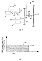
- a microturbine engine system 10 that includes a turbine section 15, a generator section 20, and a control system 25 is illustrated.
- the turbine section 15 includes a radial flow turbine 35, a compressor 45, a recuperator 50, a combustor 55, and a gearbox 60.
- the engine 10 includes a Brayton cycle combustion turbine with the recuperator 50 added to improve engine efficiency.
- the engine shown is a single-spool engine (one set of rotating elements). However, multi-spool engines are also contemplated by the invention.
- the compressor 45 is a centrifugal-type compressor having a rotary element that rotates in response to operation of the turbine 35.
- the compressor 45 shown is generally a single-stage compressor. However, multi-stage compressors can be employed where a higher pressure ratio is desired. Alternatively, compressors of different designs (e.g., axial-flow compressors, reciprocating compressors, and the like) can be employed to supply compressed air for use in the engine 10.
- the turbine 35 is a radial flow single-stage turbine having a rotary element directly coupled to the rotary element of the compressor 45. In other constructions, multi-stage turbines or other types of turbines may be employed.
- the coupled rotary elements of the turbine 35 and the compressor 45 engage the gearbox 60 or other speed reducer disposed between the turbine section 15 and the generator section 20. In other constructions, the coupled rotary elements directly engage the generator section 20.
- the recuperator 50 includes a heat exchanger employed to transfer heat from a hot fluid to the relatively cool compressed air leaving the compressor 45.
- One suitable recuperator 50 is described in U.S. Patent No. 5,983,992 .
- the recuperator 50 includes a plurality of heat exchange cells stacked on top of one another to define flow paths therebetween. The cool compressed air flows within the individual cells, while a flow of hot exhaust gas passes between the heat exchange cells.
- the rotary element of the compressor 45 rotates in response to rotation of the rotary element of the turbine 35.
- the compressor 45 draws in atmospheric air and increases its pressure.
- the highpressure air exits the air compressor 45 and flows to the recuperator 50.
- the preheated air mixes with a supply of fuel within the combustor 55 and is combusted to produce a flow of products of combustion.
- the use of the recuperator 50 to preheat the air allows for the use of less fuel to reach the desired temperature within the flow of products of combustion, thereby improving engine efficiency.
- the flow of products of combustion enters the turbine 35 and transfers thermal and kinetic energy to the turbine 35.
- the energy transfer results in rotation of the rotary element of the turbine 35 and a drop in the temperature of the products of combustion.
- the energy transfer allows the turbine 35 to drive both the compressor 45 and the generator 20.
- the products of combustion exit the turbine 35 as a first exhaust gas flow.
- the first turbine 35 drives only the compressor, while the second turbine drives the generator 20 or any other device to be driven.
- the second turbine receives the first exhaust flow, rotates in response to the flow of exhaust gas therethrough, and discharges a second exhaust flow.
- the first exhaust flow enters the flow areas between the heat exchange cells of the recuperator 50 and transfers excess heat energy to the flow of compressed air.
- the exhaust gas then exits the recuperator 50 and is discharged to the atmosphere, processed, or further used as desired (e.g., cogeneration using a second heat exchanger).
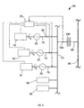
- a portion of the electrical and control systems of a power distribution system 65 is illustrated schematically.
- the microturbine engine 10 drives the generator 20 to produce an electrical output.
- the system illustrated herein includes a asynchronous generator 20, with other types of generators (e.g., high-speed alternators, asynchronous generators and the like) also functioning with the present invention.
- the generator output is delivered to a local load bus 70 via a generator output line 75.
- a generator sensor 80 positioned within the generator output line 75, measures an electrical parameter of the generator 20 during engine operation.
- the generator sensor 80 includes a current sensor.
- the measured current along with a known voltage, can be used to calculate an actual generator output power.
- Other constructions can include multiple sensors that measure current, voltage, and/or power directly.
- the generator sensor 80 can continuously monitor the electrical parameter or can take periodic measurements as desired.
- the generator output line 75 connects to, and delivers power to, the local load bus 70.
- Various local loads 85 e.g., motors, computers, monitors, robots, welding machines, lights, etc.
- multiple microturbine engine systems 10, or other generation systems are connected to the local load bus 70, with some or all of them simultaneously providing power to the power distribution system 65.
- Fig. 4 illustrates one possible system that includes multiple engine systems 10.
- Each engine system 10 is electrically connected to the local load bus 70 to allow each engine 10 to provide electrical power.
- Generator sensors 80a, 80b are positioned to measure the actual output of each engine system 10.
- the control system 25 is then able to individually control each engine 10 to produce the desired total output.
- the control system 25 is able to start or stop individual engines to optimize the system's operation, while providing the desired amount of total power.
- a tie line 90 interconnects the local load bus 70 and a utility grid 95.
- a transformer 100 may be disposed within the tie line 90 to step-up or step-down the voltage between the utility grid 95 and the local load bus 70.
- the tie line 90 facilitates the delivery of electricity from the utility grid 95 to the local load bus 70 and/or from the microturbine engine 10 to the utility grid 95.
- the tie line 90 also includes a tie line sensor 105 that measures an electrical parameter (e.g., voltage, current, absolute value of current, power, phase angle, frequency, and the like).
- the tie line sensor 105 includes a current sensor that measures both the magnitude and direction of current flow within the tie line 90.
- other constructions may include multiple sensors that measure current, voltage, and/or power flow.
- the tie line sensor 105 can continuously monitor the electrical parameter or can take periodic measurements as desired.
- the microturbine engine 10 operates intermittently.
- the tie line 90 is sized to carry sufficient electricity to power the local loads 85 during periods in which the microturbine engine 10 is inoperative.
- the generator 20 synchronized to the utility grid 95 (i.e., the voltage, phase angle, and frequency of the generator output power matched with the utility grid power)
- both the generator 20 and the utility grid 95 can provide power to the local load bus 70 and the local loads 85.
- the microturbine engine 10 includes a control system 25 that controls the operation of the engine 10 (or engines in a multiple engine system).
- the control system 25 manipulates various component (e.g., valves, pumps, compressors, louvers, switches, relays, and the like) that control various operating parameters of the engine 10.
- the control system 25 may control fuel flow to the engine 10 to control engine speed and/or power output.
- the control system 25 may move or initiate movement of a controller that in turn may manipulate a valve, a compressor, or other control member to control the flow of fuel to the combustor 55, which in turn controls the speed or the power output of the engine 10.
- the speed of the generator 20 is substantially fixed and the control system 25 controls output power.
- a power output set point is supplied to the control system 25, which then maintains the generator output at a value substantially equal to the power output set point.
- a manual control could be used. The manual control would allow a user to input a desired value between the engine's minimum and maximum output. In systems that include more than one engine 10, individual power output set points for each engine 10 may be used to control the output of each engine 10. Alternatively, a single power output set point that controls the total output of all the engines may be used.
- control system 25 would determine the specific output levels of each engine 10 using any one of a number of known schemes.
- a preprogrammed curve is used to set the power output set point.
- the curve typically defines a power output set point that varies with the time of day, day of the week, and/or day of the year.
- other parameters e.g., temperature, pressure, etc.
- Islanding conditions can arise at any time, but are particularly problematic when the power consumed by the local load 85 is very near the power level output by the generator 20. Under these "perfectly matched" circumstances, the islanding condition is very difficult to detect using known methods (e.g., rate of change of frequency ROCOF, and the like).
- the present system 65 inhibits operation of the engine 10 (or engines) in a particular range or restricted zone 115.
- the restricted zone is defined as a power flow within the tie line 90 (into or out of the utility grid 95) between zero and a predetermined minimum desired power flow 120, with the minimum desired power flow 120 being a non-zero value.
- the control system 25 receives a signal from the tie line sensor 105 indicating the level of power flow through the tie line 90. The control system 25 then compares that signal to a predetermined value representing the minimum desired power flow 120 through the tie line 90.
- the signal may represent a power flow into the local load bus 70 or a power flow to the utility grid 95.
- the power output set point is automatically adjusted. This process continues until the measured power flow through the tie line 90 exceeds the minimum desired power flow 120. With the measured power flow out of the restricted zone 115, islanding detection is much easier and is more reliable. As one of ordinary skill will realize, the actual direction of power flow (i.e. into the local load bus or out of the local load bus) does not significantly affect the ability of the present system to detect islanding so long as sufficient power is flowing. As such, the absolute value of the measured power in the tie line 90 is typically all that needs to be measured. In preferred constructions, a minimum power corresponding to a current flow of 500 amps allows for detection of islanding conditions. In still other constructions, a power flow of 100 amps or less allows for the detection of islanding. As one of ordinary skill will realize, the actual minimum desired power flow may vary greatly depending on the system employed.
- the power output set point is set at 100kW and the minimum desired power flow is set at 0.5 kW. If the local load 85 is 100kW, the microturbine engine 10 will supply all of the power to the local load 85 and no power will flow through the tie line 90. The control system 25 will detect that the flow through the tie line 90 is below the minimum desired power flow 120 and will act to either increase or decrease the power output set point. If the power output set point is reduced (to say 99 kW), power will begin flowing (1 kW) into the local load bus 70 from the utility grid 95. If on the other hand, the power output set point is increased (to say 101 kW), the microturbine engine output will increase, with the excess power (1 kW) flowing to the utility grid 95. Under either scenario, the absolute value of the measured power flow through the tie line 90 will eventually exceed the minimum desired power flow 120.
- the present system reduces the likelihood of undetected islanding conditions when the engine 10 is driving the generator 20 and producing usable electric power.
- the generator sensor 80 monitors the current flow from the generator 20 and provides feed back to the control system 25.
- the control system 25 adjusts the engine 10 to match the output power level to the power output set point.
- the tie line sensor 105 monitors the current flow through the tie line 90 and provides an additional feed back loop for the control system 25.
- the measured power flow at the tie line 90 is compared to the minimum desired power flow 120 and the power output set point is reset if the measured power flow falls below the minimum desired power flow 120.
- the power output set point can be increased or decreased as desired to assure that the measured power flow is above the minimum desired power flow 120.
- the minimum desired power flow 120 can be input by the engine user or can be preprogrammed into the control system 25.
- the actual value used is a function of many variables (e.g., engine size, instrument sensitivity, instrument accuracy, system load variations, and the like). As such, the values used herein are exemplary and should not be read as limiting in any way.
- microturbine engine 10 that drives a synchronous generator 20.
- generators e.g., high-speed alternators, asynchronous generators and the like
- system has been described as including a single master control system 25.
- the various control functions could be divided among multiple controllers or multiple control systems as desired. There is no requirement that a single control system perform all of the control functions described herein.
Landscapes
- Engineering & Computer Science (AREA)
- Power Engineering (AREA)
- Control Of Eletrric Generators (AREA)
- Supply And Distribution Of Alternating Current (AREA)
Claims (23)
- Maschinensteuersystem, das für eine Verwendung bei einer Maschine (10) geeignet ist, die Elektroenergie an einen lokalen Stromverbraucher (85) ausgibt und elektrisch mit einem elektrischen Verbundnetz (95) verbunden ist, wobei das Maschinensteuersystem aufweist:eine Sollwertsteuerung, die funktionsfähig ist, um den Maschinenausgangsleistungswert einzustellen;einen Sensor (105), der funktionsfähig ist, um einen elektrischen Parameter zwischen der Maschine (10) und dem elektrischen Verbundnetz (95) zu messen; undein Hauptsteuersystem (25), das funktionsfähig ist, um die Elektroenergie der Maschine auf über dem Maschinenausgangsleistungswert zu halten; dadurch gekennzeichnet, dass:der Sensor (105) ein Stromsensor ist und der elektrische Parameter ein Stromfluss zwischen dem elektrischen Verbundnetz (95) und der Maschine (10) ist; unddas Hauptsteuersystem (25) funktionsfähig ist, um den Maschinenausgangsleistungswert zu variieren, um den absoluten Wert des Stromflusses über 100 Ampere über einem Nichtnullvorgabewert zu halten.
- Maschinensteuersystem nach Anspruch 1, bei dem die Maschine (10) eine Verbrennungsturbine (35) umfasst, die einen Synchrongerterator (20) antreibt.
- Maschinensteuersystem nach Anspruch 1 oder 2, bei dem der Stromfluss in einer von einer ersten Richtung und einer zweiten Richtung erfolgt.
- Maschinensteuersystem nach einem der vorhergehenden Ansprüche, bei dem das Hauptsteuersystem (25) den Maschinenausgangsleistungswert variiert, um den absoluten Wert des Stromflusses über 500 Ampere zu halten.
- Verbrennungsturbinenmaschine, die funktionsfähig ist, um Elektroenergie an einen lokalen Stromverbraucher zu liefern, wobei die Maschine aufweist:einen Kompressor (45), der funktionsfähig ist, um einen Druckluftstrom zu erzeugen;eine Brennkammer (55), die den Druckluftstrom und einen Kraftstoffstrom aufnimmt und einen Strom von Verbrennungsprodukten erzeugt;eine Turbine (35), die sich als Reaktion auf den Strom der Verbrennungsprodukte dreht;einen Generator (20), der durch die Turbine (35) angetrieben wird und funktionsfähig ist, um eine Menge an Elektroenergie auszugeben, wobei der Generator (20) einen ersten elektrischen Anschluss (75), um Elektroenergie an den lokalen Stromverbraucher (85) zu liefern, und einen zweiten elektrischen Stromanschluss (90) umfasst, der den Generator (20) und das elektrische Verbundnetz (95) miteinander verbindet;wobei die Maschine außerdem ein Maschinensteuersystem nach Anspruch 1 aufweist, wobei der Sensor (105) den Stromfluss im zweiten elektrischen Anschluss (90) misst; undwobei das Hauptsteuersystem (25) Funktionsfähig ist, um den Kraftstoffstrom zur Brennkammer (55) zu variieren, um die Menge an Elektroenergie, die von der Maschine (10) ausgegeben wird, auf dem Sollwert zu halten.
- Verbrennungsturbinenmaschine nach Anspruch 5, bei der der erste elektrische Anschluss (75) eine Stromverbrauchersammelleitung (70) umfasst und der zweite elektrische Anschluss (90) die Stromverbrauchersammelleitung (70) und das elektrische Verbundnetz (95) so miteinander verbindet, dass Elektroenergie von der Stromverbrauchersammelleitung (70) zum elektrischen Verbundnetz (95) geliefert werden kann, und dass Strom vom elektrischen Verbundnetz (95) zur Stromverbrauchersammelleitung (70) geliefert werden kann.
- Verbrennungsturbinenmaschine nach Anspruch 6, bei der der Generator (20) elektrisch mit der Stromverbrauchersammelleitung (70) verbunden ist und der lokale Stromverbraucher (85) elektrisch mit der Stromverbrauchersammelleitung (70) verbunden ist.
- Verbrennungsturbinenmaschine nach einem der Ansprüche 5 bis 7, bei der der Generator (20) einen Synchrongenerator umfasst.
- Verbrennungsturbinenmaschine nach einem der Ansprüche 5 bis 8, bei der der Stromfluss in einer von einer ersten Richtung und einer zweiten Richtung erfolgt.
- Verbrennungsturbinenmaschine nach einem der Ansprüche 5 bis 9, bei der das Hauptsteuersystem (25) den Maschinenausgangsleistungswert variiert, um den absoluten Wert des Stromflusses über 500 Ampere zu halten.
- Stromerzeugungssystem, das funktionsfähig ist, um Elektroenergie zu mindestens einem von einem lokalen Stromverbraucher (85) und einem Verbundnetz (95) zu liefern, wobei das System aufweist:eine lokale Stromverbrauchersammelleitung (70), die elektrisch mit dem Verbundnetz (95) verbunden ist und Elektroenergie zu einem lokalen Stromverbraucher liefert;eine Vielzahl von Maschinen-Generator-Gruppen, die elektrisch mit der lokalen Stromverbrauchersammelleitung (70) verbunden sind, wobei mindestens eine der Vielzahl von Maschinen-Generator-Gruppen funktionsfähig ist, um eine Strommenge zur lokalen Stromverbrauchersammelleitung (70) zu liefern; undein Maschinensteuersystem nach Anspruch 1, bei demdie Sollwertsteuerung funktionsfähig ist, um den Systemausgangsleistungswert einzustellen;der Sensor (105) funktionsfähig ist, um den Stromfluss zwischen der Vielzahl der Maschinen-Generator-Gruppen und dem Verbundnetz (95) zu messen; unddas Hauptsteuersystem (25) funktionsfähig ist, um die Menge an Strom, die von mindestens einer der Vielzahl von Maschinen-Generator-Gruppen erzeugt wird, auf etwa dem Systemausgangsleistungswert zu halten, wobei das Hauptsteuersystem ebenfalls funktionsfähig ist, um den Systemausgangsleistungswert so zu verändern, dass die Strommenge, die der lokalen Stromverbrauchersammelleitung (70) zugeführt wird, dem lokalen Stromverbraucher (85) nicht gleich ist.
- Stromerzeugungssystem nach Anspruch 11, bei dem eine jede der Vielzahl von Maschinen-Generator-Gruppen eine Verbrennungsturbine (35) umfasst.
- Stromerzeugungssystem nach Anspruch 11 oder 12, bei dem der Sensor einen Stromfluss zwischen dem Verbundnetz (95) und der lokalen Stromverbrauchersammelleitung (70) misst.
- Stromerzeugungssystem nach einem der Ansprüche 11 bis 13, bei dem der Stromfluss in einer von einer ersten Richtung und einer zweiten Richtung erfolgt.
- Stromerzeugungssystem nach einem der Ansprüche 11 bis 14, bei dem das Hauptsteuersystem funktionsfähig ist, um den Betrieb einer jeden der Vielzahl von Maschinen-Generator-Gruppen einzuleiten und zu beenden.
- Stromerzeugungssystem nach einem der Ansprüche 11 bis 15, bei dem das Hauptsteuersystem (25) einen Ausgangsleistungssollwert für eine jede der Vielzahl der Maschinen-Generator-Gruppen festlegt.
- Verfahren zum Betätigen einer Maschine (10), die Elektroenergie an einen lokalen Stromverbraucher (85) liefert und elektrisch mit einem elektrischen Verbundnetz (95) verbunden ist, wobei das Verfahren die folgenden Schritte aufweist:Eingeben eines Gesamtstromsollwertes in ein Hauptsteuersystem (25);Betätigen der Maschine (10), um eine Ausgangsleistung zu erzeugen, die im Wesentlichen gleich dem Gesamtstromsollwert ist;Messen eines Stromflusses an einer Stelle (90) zwischen der Maschine (10) und dem elektrischen Verbundnetz (95); undVerändern des Gesamtstromsollwertes, um den absoluten Wert des Stromflusses über 100 Ampere zu halten.
- Verfahren nach Anspruch 17, das außerdem den Schritt des periodischen Veränderns einer an die Maschine (10) angelegten Last aufweist.
- Verfahren nach Anspruch 17 oder 19, das außerdem den Schritt des Messens eines Stromflusses zwischen der Maschine (10) und dem lokalen Stromverbraucher (85) aufweist.
- Verfahren nach einem der Ansprüche 17 bis 19, bei dem das Hauptsteuersystem die Ausgangsleistung der Maschine (10) auf einem Wert hält, der im Wesentlichen gleich dem Gesamtstromsollwert ist.
- Verfahren nach Anspruch 17, bei dem die Maschine (10) elektrisch eine Verbindung mit einer Sammelleitung (70) aufweist, die elektrisch mit dem Verbundnetz (95) verbunden ist, und die dem lokalen Stromverbraucher (85) Elektroenergie liefert, und wobei das Verfahren die Schritte des Messens des Stromes, der zwischen dem Verbundnetz (95) und der Sammelleitung (70) fließt, und des Regulierens der Ausgangsleistung der Maschine umfasst, die sich nicht an den lokalen Stromverbraucher (85) anpasst.
- Verfahren nach Anspruch 21, bei dem der Stromfluss zwischen dem Verbundnetz (95) und der Sammelleitung (70) gemessen wird.
- Verfahren nach Anspruch 21 oder 22, das außerdem den Schritt des Messens der Ausgangsleistung der Maschine (10) aufweist.
Applications Claiming Priority (2)
| Application Number | Priority Date | Filing Date | Title |
|---|---|---|---|
| US10/795,953 US7161257B2 (en) | 2004-03-08 | 2004-03-08 | Active anti-islanding system and method |
| US795953 | 2004-03-08 |
Publications (3)
| Publication Number | Publication Date |
|---|---|
| EP1574672A2 EP1574672A2 (de) | 2005-09-14 |
| EP1574672A3 EP1574672A3 (de) | 2007-01-24 |
| EP1574672B1 true EP1574672B1 (de) | 2012-08-29 |
Family
ID=34827601
Family Applications (1)
| Application Number | Title | Priority Date | Filing Date |
|---|---|---|---|
| EP05250713A Expired - Lifetime EP1574672B1 (de) | 2004-03-08 | 2005-02-08 | Anti-Isolierungssystem für ein elektrisches Kraftwerk und sein Verfahren |
Country Status (2)
| Country | Link |
|---|---|
| US (2) | US7161257B2 (de) |
| EP (1) | EP1574672B1 (de) |
Families Citing this family (13)
| Publication number | Priority date | Publication date | Assignee | Title |
|---|---|---|---|---|
| US7161257B2 (en) | 2004-03-08 | 2007-01-09 | Ingersoll-Rand Energy Systems, Inc. | Active anti-islanding system and method |
| ITTO20050712A1 (it) * | 2005-10-07 | 2007-04-08 | Ansaldo Ricerche S P A | Sistema di generazione di energia elettrica |
| ITTO20050711A1 (it) * | 2005-10-07 | 2007-04-08 | Ansaldo Ricerche S P A | Rete di distribuzione di energia di tipo riconfigurabile |
| JP4575272B2 (ja) | 2005-10-27 | 2010-11-04 | 株式会社日立製作所 | 分散型電源システム及び系統安定化方法 |
| US7319307B2 (en) * | 2005-12-16 | 2008-01-15 | General Electric Company | Power balancing of multiple synchronized generators |
| DE102006032007A1 (de) * | 2006-07-10 | 2008-01-24 | Patent-Treuhand-Gesellschaft für elektrische Glühlampen mbH | Energieumwandler-Modul und Leucht-Vorrichtung |
| US7457688B2 (en) * | 2006-09-19 | 2008-11-25 | General Electric Company | Method and system for detection and transfer to electrical island operation |
| GB0810512D0 (en) | 2008-06-10 | 2008-07-09 | Rolls Royce Plc | An electrical generator network and a local electrical system |
| US8334618B2 (en) | 2009-11-13 | 2012-12-18 | Eaton Corporation | Method and area electric power system detecting islanding by employing controlled reactive power injection by a number of inverters |
| WO2011094414A2 (en) * | 2010-01-27 | 2011-08-04 | Dresser-Rand Company | Advanced topologies for offshore power systems |
| US8532834B2 (en) * | 2010-10-29 | 2013-09-10 | Hatch Ltd. | Method for integrating controls for captive power generation facilities with controls for metallurgical facilities |
| US9620994B2 (en) | 2013-01-17 | 2017-04-11 | Eaton Corporation | Method and system of anti-islanding of a microgrid in a grid-connected microgrid system |
| EP2858201A1 (de) * | 2013-10-07 | 2015-04-08 | ABB Technology AG | Erkennung von Inselbildungsbedingungen in Stromnetz |
Family Cites Families (77)
| Publication number | Priority date | Publication date | Assignee | Title |
|---|---|---|---|---|
| US3499164A (en) * | 1967-05-05 | 1970-03-03 | Caterpillar Tractor Co | Excitation control system for prime mover driven generator |
| US3491248A (en) | 1967-08-11 | 1970-01-20 | Gulton Ind Inc | Power transmission line switch control system |
| CH479199A (de) | 1969-01-28 | 1969-09-30 | Armand Dipl Ing Brandt | Stromrichtermotor mit einer Einrichtung für stufenlose Drehzahlregelung |
| US3750001A (en) | 1969-11-28 | 1973-07-31 | E Mccloskey | Remote, completely self-contained, self-maintaining power supply apparatus for powering a pressurized-liquid distributing and disseminating system |
| US3599007A (en) | 1969-12-29 | 1971-08-10 | Bell Telephone Labor Inc | Digital synchronizer check and synchroscope |
| US4031407A (en) | 1970-12-18 | 1977-06-21 | Westinghouse Electric Corporation | System and method employing a digital computer with improved programmed operation for automatically synchronizing a gas turbine or other electric power plant generator with a power system |
| BE790067A (fr) | 1971-10-13 | 1973-04-13 | Westinghouse Air Brake Co | Systeme de commande de moteur |
| US3794846A (en) | 1972-09-18 | 1974-02-26 | Electric Machinery Mfg Co | Automatic synchronizing control system |
| US3953779A (en) | 1974-05-30 | 1976-04-27 | Francisc Carol Schwarz | Electronic control system for efficient transfer of power through resonant circuits |
| US3975646A (en) | 1975-01-13 | 1976-08-17 | Westinghouse Electric Corporation | Asynchronous tie |
| US4039909A (en) | 1975-02-10 | 1977-08-02 | Massachusetts Institute Of Technology | Variable speed electronic motor and the like |
| US4001666A (en) | 1975-04-03 | 1977-01-04 | General Electric Company | Load peak shaver power regulating system |
| JPS5330718A (en) | 1976-09-03 | 1978-03-23 | Hitachi Ltd | Controller for motor |
| US4276482A (en) | 1977-06-03 | 1981-06-30 | Otis Engineering Corporation | Line flow electric power generator |
| US4142367A (en) | 1977-10-17 | 1979-03-06 | Eleanor A. Guisti Dondero | Domestic water pressure-flow powered generator system |
| JPS5855759B2 (ja) | 1978-01-11 | 1983-12-12 | 株式会社日立製作所 | 誘導電動機の制御装置 |
| US4227136A (en) | 1978-07-17 | 1980-10-07 | Precise Power Corporation | Variable speed A.C. motor |
| JPS5534854A (en) | 1978-09-04 | 1980-03-11 | Hitachi Ltd | Controlling method of secondary winding-exciting motor |
| JPS55111677A (en) | 1979-02-20 | 1980-08-28 | Toshiba Corp | System for starting commutatorless motor |
| US4256972A (en) | 1979-05-10 | 1981-03-17 | Beckwith Electric Co., Inc. | Power transfer relay circuitry and method of phase measurement |
| US4249120A (en) | 1979-07-26 | 1981-02-03 | Mcgraw-Edison Co. | Variable speed induction motor control system |
| US4417194A (en) * | 1980-09-18 | 1983-11-22 | The Charles Stark Draper Laboratory, Inc. | Induction generator system with switched capacitor control |
| US4401938A (en) | 1980-12-29 | 1983-08-30 | Lockheed Corporation | Variable-speed drive for control of induction generators |
| US4352024A (en) | 1981-05-04 | 1982-09-28 | Carrier Corporation | Expander-generator control system |
| US4426611A (en) | 1982-04-28 | 1984-01-17 | General Electric Company | Twelve pulse load commutated inverter drive system |
| US4476424A (en) | 1982-05-03 | 1984-10-09 | The Garrett Corporation | Variable speed induction motor drive system |
| DE3227700A1 (de) | 1982-07-24 | 1984-01-26 | BÖWE Maschinenfabrik GmbH, 8900 Augsburg | Windenergiekonverter |
| US4455522A (en) | 1982-08-02 | 1984-06-19 | General Electric Company | Current source inverter bed induction motor drive |
| US4791309A (en) | 1982-09-21 | 1988-12-13 | Thamesmead Engineering Limited | Electrical control systems |
| US4672298A (en) | 1983-05-06 | 1987-06-09 | Frederick Rohatyn | Power factor correction system |
| US4533835A (en) | 1984-03-15 | 1985-08-06 | Sterling Beckwith | Control apparatus for hydraulically driven generator |
| US4701691A (en) | 1985-05-14 | 1987-10-20 | Nickoladze Leo G | Synchronous generators |
| EP0220492B1 (de) | 1985-09-25 | 1991-03-06 | Hitachi, Ltd. | Regelsystem für einen hydraulischen Turbinengenerator mit variabler Geschwindigkeit |
| US4723104A (en) | 1985-10-02 | 1988-02-02 | Frederick Rohatyn | Energy saving system for larger three phase induction motors |
| JP2515730B2 (ja) | 1985-10-04 | 1996-07-10 | 株式会社日立製作所 | 電気車の制御装置 |
| DE3601288A1 (de) | 1986-01-17 | 1987-07-23 | Siemens Ag | Wassergetriebener maschinensatz mit wirkungsgradoptimaler vorgabe des drehzahlsollwertes |
| US4743777A (en) | 1986-03-07 | 1988-05-10 | Westinghouse Electric Corp. | Starter generator system with two stator exciter windings |
| EP0243937B1 (de) | 1986-04-30 | 1991-05-29 | Hitachi, Ltd. | Energiegeneratorsystem vom Pumpen-Aufschlagstyp mit veränderlicher Geschwindigkeit |
| JPS6318995A (ja) | 1986-07-11 | 1988-01-26 | Toshiba Corp | 巻線型誘導発電機の電圧制御装置 |
| US4710692A (en) | 1986-10-16 | 1987-12-01 | Square D Company | Self calibration of the thyristor firing angel of a motor controller using a current window to determine a final value of a reference current lag phase angle |
| JP2813775B2 (ja) * | 1988-08-05 | 1998-10-22 | 日本電信電話株式会社 | 直流給電装置 |
| US5028804A (en) * | 1989-06-30 | 1991-07-02 | The State Of Oregon Acting By And Through The State Board Of Higher Education On Behalf Of Oregon State University | Brushless doubly-fed generator control system |
| JP2730595B2 (ja) | 1989-08-21 | 1998-03-25 | 株式会社 四国総合研究所 | 小型発電装置の系統連系装置 |
| JPH03256533A (ja) | 1990-03-02 | 1991-11-15 | Shikoku Sogo Kenkyusho:Kk | 系統連系システム |
| JP2758782B2 (ja) | 1992-05-22 | 1998-05-28 | 三菱電機株式会社 | 電源装置 |
| JP3139834B2 (ja) | 1992-06-24 | 2001-03-05 | 東芝エフエーシステムエンジニアリング株式会社 | 系統連系保護装置 |
| JP3180991B2 (ja) | 1993-05-07 | 2001-07-03 | 東芝アイティー・コントロールシステム株式会社 | 系統連系保護装置 |
| AU655889B2 (en) | 1992-06-24 | 1995-01-12 | Kabushiki Kaisha Toshiba | Inverter protection device |
| JPH06141470A (ja) | 1992-10-22 | 1994-05-20 | Toshiba F Ee Syst Eng Kk | 系統連系インバータの保護装置 |
| JP3029185B2 (ja) | 1994-04-12 | 2000-04-04 | キヤノン株式会社 | 単独運転防止装置、それを用いた分散型発電装置及び発電システム |
| JP3353549B2 (ja) | 1995-03-30 | 2002-12-03 | 富士電機株式会社 | 系統連系用インバータの単独運転検出装置 |
| DE69623692T2 (de) | 1995-05-31 | 2003-05-22 | Kabushiki Kaisha Meidensha, Tokio/Tokyo | Verfahren und Vorrichtung zum Detektieren des Islanding-Betriebes eines verteilten Generators |
| ES2146459T3 (es) | 1996-02-01 | 2000-08-01 | Northern Res & Eng | Intercambiador de calor de placas con aletas. |
| JP3302875B2 (ja) | 1996-03-12 | 2002-07-15 | 東芝アイティー・コントロールシステム株式会社 | 系統連系保護用無効電力補償装置 |
| JP3227480B2 (ja) | 1996-05-29 | 2001-11-12 | シャープ株式会社 | インバータ装置の単独運転検知方法、およびインバータ装置 |
| WO1998029933A1 (fr) * | 1996-12-26 | 1998-07-09 | Kabushiki Kaisha Toshiba | Dispositif de protection des interconnexions systemes pour generateur independant |
| JP3627948B2 (ja) | 1997-03-10 | 2005-03-09 | 関西電力株式会社 | 系統連系用インバータの単独運転防止装置 |
| US5998880A (en) * | 1997-08-07 | 1999-12-07 | General Electric Company | AC locomotive operation without DC current sensor |
| US6784565B2 (en) | 1997-09-08 | 2004-08-31 | Capstone Turbine Corporation | Turbogenerator with electrical brake |
| JP4076721B2 (ja) | 1997-11-24 | 2008-04-16 | エイチ. ウィルス、ロバート | 分散型発電用耐単独運転方法および装置 |
| US5992950A (en) * | 1998-03-30 | 1999-11-30 | General Electric Company | Controlled stop function for locomotives |
| US20030007369A1 (en) | 1998-04-02 | 2003-01-09 | Gilbreth Mark G. | Power controller |
| US6429546B1 (en) | 1998-11-20 | 2002-08-06 | Georgia Tech Research Corporation | Systems and methods for preventing islanding of grid-connected electrical power systems |
| US6545885B2 (en) | 2000-03-13 | 2003-04-08 | Nissin Electric Co., Ltd. | Isolated operation prevention device for distributed power supply and interharmonic detection method |
| JP3420162B2 (ja) * | 2000-03-23 | 2003-06-23 | 西芝電機株式会社 | 発電設備の系統連系保護装置 |
| GB2370702B (en) | 2000-09-19 | 2003-07-09 | Toshiba Kk | Line linkage protective device for electricity generation equipment |
| US6281595B1 (en) * | 2000-09-25 | 2001-08-28 | General Electric Company | Microturbine based power generation system and method |
| US6815932B2 (en) | 2000-10-12 | 2004-11-09 | Capstone Turbine Corporation | Detection of islanded behavior and anti-islanding protection of a generator in grid-connected mode |
| US6603672B1 (en) * | 2000-11-10 | 2003-08-05 | Ballard Power Systems Corporation | Power converter system |
| US6787933B2 (en) | 2001-01-10 | 2004-09-07 | Capstone Turbine Corporation | Power generation system having transient ride-through/load-leveling capabilities |
| EP1278282A1 (de) | 2001-07-16 | 2003-01-22 | Abb Research Ltd. | Verfahren und Vorrichtung zum isolieren eines ersten Teiles eines elektrischen Netzes vom zweiten Teil des elektrischen Netz |
| AU2002357670A1 (en) | 2001-10-26 | 2003-05-12 | Youtility, Inc. | Anti-islanding techniques for distributed power generation |
| US6603290B2 (en) | 2001-11-26 | 2003-08-05 | Visteon Global Technologies, Inc. | Anti-islanding detection scheme for distributed power generation |
| US6920387B2 (en) * | 2001-12-06 | 2005-07-19 | Caterpillar Inc | Method and apparatus for parasitic load compensation |
| WO2003106828A2 (en) * | 2002-06-18 | 2003-12-24 | Ingersoll-Rand Energy Systems Corporation | Microturbine engine system |
| JP2004257285A (ja) * | 2003-02-25 | 2004-09-16 | Honda Motor Co Ltd | エンジン駆動式発電装置 |
| US7161257B2 (en) * | 2004-03-08 | 2007-01-09 | Ingersoll-Rand Energy Systems, Inc. | Active anti-islanding system and method |
-
2004
- 2004-03-08 US US10/795,953 patent/US7161257B2/en not_active Expired - Fee Related
-
2005
- 2005-02-08 EP EP05250713A patent/EP1574672B1/de not_active Expired - Lifetime
-
2006
- 2006-11-27 US US11/563,333 patent/US7365444B2/en not_active Expired - Lifetime
Also Published As
| Publication number | Publication date |
|---|---|
| US20070096471A1 (en) | 2007-05-03 |
| EP1574672A2 (de) | 2005-09-14 |
| US7161257B2 (en) | 2007-01-09 |
| EP1574672A3 (de) | 2007-01-24 |
| US20050194789A1 (en) | 2005-09-08 |
| US7365444B2 (en) | 2008-04-29 |
Similar Documents
| Publication | Publication Date | Title |
|---|---|---|
| AU751806B2 (en) | Constant turbine inlet temperature control of a microturbine power generating system | |
| EP1761984B1 (de) | Motorisiertes wechselrichtersystem mit kraft/wärme-kopplung | |
| US6198174B1 (en) | Microturbine power generating system | |
| EP1574672B1 (de) | Anti-Isolierungssystem für ein elektrisches Kraftwerk und sein Verfahren | |
| KR102587241B1 (ko) | 육상 또는 해양 기반의 다중-스풀 가스 터빈을 작동시키기 위한 시스템, 방법 및 컴퓨터 프로그램 | |
| US7122916B2 (en) | Multi-unit power generation system for stand-alone and grid connected operation | |
| US6170251B1 (en) | Single shaft microturbine power generating system including turbocompressor and auxiliary recuperator | |
| US9605556B2 (en) | Power station and method for its operation | |
| CN102996252B (zh) | 用于操作联合循环电厂的方法 | |
| US6147414A (en) | Dual-purpose converter/startup circuit for a microturbine power generating system | |
| WO1999032762A1 (en) | An uninterruptible microturbine power generating system | |
| US6032459A (en) | Turbine exhaust cooling in a microturbine power generating system | |
| EP3274562A1 (de) | Mehrspulige gasturbinenanordnung | |
| EP3800756A1 (de) | Verfahren und systeme zur schnellen lastunterstützung für transiente netzfrequenzereignisse | |
| US6854274B2 (en) | System and method for efficient load following control logic for a turbogenerator operating in stand-alone mode | |
| JP2019113061A (ja) | 二重駆動発電機のためのシステムおよび方法 | |
| EP1059421B1 (de) | Mikroturbinenkraftanlage | |
| EP2072609A1 (de) | Erdgasverflüssigungsanlage und stromversorgungssystem, steuergerät und betriebsverfahren dafür | |
| CA2273813C (en) | Microturbine power generating system | |
| AU772937B2 (en) | Microturbine power generating system | |
| IL158305A (en) | A microtorbine system that produces power | |
| IL130434A (en) | A microtorbine system that produces power |
Legal Events
| Date | Code | Title | Description |
|---|---|---|---|
| PUAI | Public reference made under article 153(3) epc to a published international application that has entered the european phase |
Free format text: ORIGINAL CODE: 0009012 |
|
| AK | Designated contracting states |
Kind code of ref document: A2 Designated state(s): AT BE BG CH CY CZ DE DK EE ES FI FR GB GR HU IE IS IT LI LT LU MC NL PL PT RO SE SI SK TR |
|
| AX | Request for extension of the european patent |
Extension state: AL BA HR LV MK YU |
|
| PUAL | Search report despatched |
Free format text: ORIGINAL CODE: 0009013 |
|
| AK | Designated contracting states |
Kind code of ref document: A3 Designated state(s): AT BE BG CH CY CZ DE DK EE ES FI FR GB GR HU IE IS IT LI LT LU MC NL PL PT RO SE SI SK TR |
|
| AX | Request for extension of the european patent |
Extension state: AL BA HR LV MK YU |
|
| RIC1 | Information provided on ipc code assigned before grant |
Ipc: H02J 3/38 20060101ALI20061218BHEP Ipc: H02J 3/06 20060101AFI20061218BHEP Ipc: F02C 9/26 20060101ALI20061218BHEP Ipc: F01D 15/10 20060101ALI20061218BHEP Ipc: H02P 9/04 20060101ALI20061218BHEP |
|
| 17P | Request for examination filed |
Effective date: 20070703 |
|
| AKX | Designation fees paid |
Designated state(s): FR GB |
|
| REG | Reference to a national code |
Ref country code: DE Ref legal event code: 8566 |
|
| 17Q | First examination report despatched |
Effective date: 20090416 |
|
| GRAP | Despatch of communication of intention to grant a patent |
Free format text: ORIGINAL CODE: EPIDOSNIGR1 |
|
| GRAS | Grant fee paid |
Free format text: ORIGINAL CODE: EPIDOSNIGR3 |
|
| GRAA | (expected) grant |
Free format text: ORIGINAL CODE: 0009210 |
|
| AK | Designated contracting states |
Kind code of ref document: B1 Designated state(s): FR GB |
|
| REG | Reference to a national code |
Ref country code: GB Ref legal event code: FG4D |
|
| PLBE | No opposition filed within time limit |
Free format text: ORIGINAL CODE: 0009261 |
|
| STAA | Information on the status of an ep patent application or granted ep patent |
Free format text: STATUS: NO OPPOSITION FILED WITHIN TIME LIMIT |
|
| 26N | No opposition filed |
Effective date: 20130530 |
|
| REG | Reference to a national code |
Ref country code: FR Ref legal event code: PLFP Year of fee payment: 12 |
|
| REG | Reference to a national code |
Ref country code: FR Ref legal event code: PLFP Year of fee payment: 13 |
|
| PGFP | Annual fee paid to national office [announced via postgrant information from national office to epo] |
Ref country code: FR Payment date: 20170112 Year of fee payment: 13 |
|
| PGFP | Annual fee paid to national office [announced via postgrant information from national office to epo] |
Ref country code: GB Payment date: 20170208 Year of fee payment: 13 |
|
| GBPC | Gb: european patent ceased through non-payment of renewal fee |
Effective date: 20180208 |
|
| REG | Reference to a national code |
Ref country code: FR Ref legal event code: ST Effective date: 20181031 |
|
| PG25 | Lapsed in a contracting state [announced via postgrant information from national office to epo] |
Ref country code: GB Free format text: LAPSE BECAUSE OF NON-PAYMENT OF DUE FEES Effective date: 20180208 Ref country code: FR Free format text: LAPSE BECAUSE OF NON-PAYMENT OF DUE FEES Effective date: 20180228 |