EP1574471A2 - Dispositif pour décorer les mur d'une cabine d'ascenseur - Google Patents
Dispositif pour décorer les mur d'une cabine d'ascenseur Download PDFInfo
- Publication number
- EP1574471A2 EP1574471A2 EP04027822A EP04027822A EP1574471A2 EP 1574471 A2 EP1574471 A2 EP 1574471A2 EP 04027822 A EP04027822 A EP 04027822A EP 04027822 A EP04027822 A EP 04027822A EP 1574471 A2 EP1574471 A2 EP 1574471A2
- Authority
- EP
- European Patent Office
- Prior art keywords
- reversible fastening
- fastening device
- adhesive component
- panel
- wall
- Prior art date
- Legal status (The legal status is an assumption and is not a legal conclusion. Google has not performed a legal analysis and makes no representation as to the accuracy of the status listed.)
- Withdrawn
Links
Images


Classifications
-
- B—PERFORMING OPERATIONS; TRANSPORTING
- B66—HOISTING; LIFTING; HAULING
- B66B—ELEVATORS; ESCALATORS OR MOVING WALKWAYS
- B66B11/00—Main component parts of lifts in, or associated with, buildings or other structures
- B66B11/02—Cages, i.e. cars
- B66B11/0226—Constructional features, e.g. walls assembly, decorative panels, comfort equipment, thermal or sound insulation
-
- E—FIXED CONSTRUCTIONS
- E04—BUILDING
- E04F—FINISHING WORK ON BUILDINGS, e.g. STAIRS, FLOORS
- E04F13/00—Coverings or linings, e.g. for walls or ceilings
- E04F13/07—Coverings or linings, e.g. for walls or ceilings composed of covering or lining elements; Sub-structures therefor; Fastening means therefor
- E04F13/08—Coverings or linings, e.g. for walls or ceilings composed of covering or lining elements; Sub-structures therefor; Fastening means therefor composed of a plurality of similar covering or lining elements
- E04F13/088—Coverings or linings, e.g. for walls or ceilings composed of covering or lining elements; Sub-structures therefor; Fastening means therefor composed of a plurality of similar covering or lining elements fixed directly to the wall by means of magnets, hook and loop-type or similar fasteners, not necessarily involving the side faces of the covering element
-
- B—PERFORMING OPERATIONS; TRANSPORTING
- B66—HOISTING; LIFTING; HAULING
- B66B—ELEVATORS; ESCALATORS OR MOVING WALKWAYS
- B66B19/00—Mining-hoist operation
- B66B19/007—Mining-hoist operation method for modernisation of elevators
Definitions
- the present invention relates to a device for Covering areas in the area of a lift, a cladding for a wall of a cabin of a lift, one Wall for an elevator car and an elevator car.
- Walls of elevator cabins or cars are in elevators For people and / or loads usually made of sheet metal.
- the insides of the cars of elevators for persons or Loads are therefore very often disguises, i.
- Side and rear walls of the cabs are by area Covered panels, as well as the cabin ceilings and the floor-facing surfaces of doors and door frames.
- the object of the invention is an equipment of walls for elevator cars with fairings, so the possibility a covering of such walls, to improve.
- the Invention should u.a. an assembly of panels of such Walls are both simplified and cheaper be.
- walls for elevator cabins be more advantageous overall equip, so that for example, also technical advantages for an operation of an elevator installation, in which the elevator car drives, surrendered.
- This task comes with a feature with the features of claim 1, a panel with the features of claim 18, a wall with the features of Patent claim 19 and an elevator car with the features of claim 20 solved.
- the inventive device for dressing surfaces in the area of elevators has at least one fairing and at least one of two interacting, planar ones Adhesive components formed reversible fastening device on.
- a first adhesive component the at least one reversible fastening device the cladding and in each case a second adhesive component of at least one reversible fastening device on the arranged to be covered area.
- the at least one reversible fastening device as a flexible or flexible pressure sealing strip is formed or are.
- the reversible fastening device is therefore as a so-called Velcro closure or Surface adhesive closure with tentacle adhesive or with e.g. Hemispherical head formed.
- Such reversible fastening devices have the advantage that through them, so by means of the two interacting adhesive components between the panel and the wall, a secure connection quick and easy to prepare as well as uncomplicated Non-destructive manner is releasable again.
- the one adhesive component is fixed to the back the cladding panel connected, e.g. glued, screwed, riveted or welded, and the other with the one to be clad Area.
- the inventive Facility offers the possibility of a fast and uncomplicated optical change of the elevator car.
- On individual customer wishes concerning the equipment can be independent of a technical embodiment of the Raw cabin or an existing, to be modernized Elevator cab flexible, easy and efficient become. In the latter case, it is only necessary to the existing wall, the second planar adhesive components to arrange the reversible fastening device.
- the two adhesive components of the at least one reversible Fastening device can on the one hand different Have structures. So can one of the two adhesive components a plurality of surface arranged, preferably eyelet or loop-like engagement means for the reversible, easily detachable hook or tentacle hooking device which are attached to the second adhesive component in one of the plurality of engagement means largely corresponding Number are arranged flat.
- the flexible pressure closure with on both Pages of essentially similar individual structures, such as. with hemispherical heads on a short stem, e.g. Dual lock.
- the flexible pressure closure self-adhesive, so that on the one Side of each adhesive component the hemisphere heads and on the On the other side of each adhesive component an adhesive is arranged is with which the component on the trim panel or is glued to the surface to be covered.
- the first adhesive component is at least a reversible fastening device on the panel and the second adhesive component of the at least one reversible Fastening device on the wall of the elevator car glued.
- the panel provided several reversible fastening devices, so these are preferably evenly spaced under symmetric, regular alignment between the wall and the paneling arranged.
- the first and the second adhesive component each of a reversible fastening device are thus congruent or mirror image both on the cladding and on the wall attached.
- With appropriate arrangement of the reversible fastening devices is it possible, for example, disguises on the wall of the elevator car both horizontally and also to arrange vertically or attach.
- With the reversible Fastener is between the panel and provided a secure, externally invisible connection to the wall.
- the at least one panel of a Carrier material and at least one adhered thereto Surface material is formed.
- the surface material is preferably as a stainless steel sheet educated.
- edible metals such as any Stainless steel textured sheets can be used.
- the surface material may also be made of plastic, textile material, Wood and the like or as a mirror be educated. Accordingly, for this surface material depending on optical, customer-specific requirements any suitable, for example, also flame retardant Material to be selected.
- the support material can be particularly advantageous as metallic Lightweight board, in particular as an aluminum lightweight board, be educated.
- This lightweight board consists of e.g. consisting of two cover sheets and one in between Sheet metal, the periodically repeating deformations and thus wavy or possibly zigzag is trained.
- the carrier material thus advantageously has a sandwich or honeycomb-like structure.
- This structure has to Advantage that this substrate is particularly light, thin-walled and also resistant to bending. Due to the small thickness the device according to the invention is the base of the Elevator car only slightly affected.
- the overall weight of the elevator car is substantially reduced compared to elevator cabins with conventional cowling equipment.
- a significant weight saving can be achieved with the device according to the invention, which makes it possible, for example, to use a smaller counterweight and thus also a smaller drive for the elevator.
- the low mass of the panel favors the assembly or disassembly of the panel, since the parts to be handled are considerably lighter than previous panels.
- the device according to the invention is a modular Equipment for interior walls, ie side and / or rear walls possible from elevator cabins. It lends itself here, two adjacent panels so relative to each other, preferably parallel to each other, relative to the wall of the elevator car to arrange that between these panels due to a spacing of these panels a Shadow gap arises. Depending on the optical requirements can in a region of this shadow gap on the wall a stainless steel strip or a, for example, black plastic strip be glued on. With the device according to the invention is It is possible to take into account a width of the shadow gap a division, for example, a panel-like trained Surface material to vary as desired. An advantageous Shadow gap width is about 8 mm, but can also only 3 mm.
- the shadow gap can also be used to attach a handrail or other cabin fixtures directly on the wall too allow to work without the panel in addition to have to.
- the elevator car is an insert of a skirting board conceivable on which the panel during assembly is to be set up.
- the wall of the elevator car or car of the elevator is usually formed of sheet metal wall slats. Because the Fastening of the cladding eg. Of cladding panels through the flexible pressure lock and this e.g. in relation to double-sided tape a considerably greater intrinsic thickness often, e.g. about 4 mm, can the division the cladding panels regardless of a classification of Wall lamellae are made without any attachment problems gives.
- the lining according to the invention for a wall of an elevator car each has a first planar adhesive component at least one of two interacting, planar Adhesive components formed reversible fastening device on.
- a first planar adhesive component with a each second planar adhesive component of the at least a reversible attachment device attached to the wall is arranged to connect.
- the respective second planar adhesive component with a respective first planar adhesive component of at least a reversible fastening device, which on a Cladding is arranged to connect.
- the inventive Wall for the elevator car is in a simple way equipped with one or more panels.
- the elevator car according to the invention with a number of Walls are provided that on at least one of the walls at least one second area adhesive component at least one of two cooperating, flat adhesive components trained reversible fastening device arranged is.
- a respective first surface adhesive component the reversible fastening device, which at a Cladding is arranged, with each second flat Bonding component to connect.
- the elevator car according to the invention or Rohkabine for a lift can thus under little effort according to individual requirements with a or more side by side facing panels be equipped or even with several against each other exchangeable cladding panels for e.g. one Car in blue or stainless steel.
- Figure 1 shows a schematic representation of a horizontal Section through two mutually perpendicular, preferably formed from wall panels walls 4 of an elevator car 6. On these walls 4 are for dressing or to the equipment of the walls 4 or at least partially Cover the walls 4 panels 2 arranged or attached. On one of the two walls is also a Mirror 26 arranged or attached. A handrail 27 is via a handrail fastening 29 in the area of a shadow gap 24 between two panels 2 directly on the wall. 4 attached. In the sense of an advantageous figurative representation are the panels 2, the walls 4 and the Mirror 26 and the handrail 27 shortened, ie in the plane of the drawing cut, pictured.
- the panels 2 are made of a carrier material 16, in particular Metal or aluminum lightweight panels as well on it glued surface material 14, eg. Of stainless steel educated.
- a compound of the panels 2 with the wall 4 or a Attachment of the panels 2 on the walls 4 is about reversible fastening devices 8, so flexible Ziplock strips, Dual Lock, or Velcro closures provided. Details of advantageous embodiments the panels 2 and the reversible fastening devices 8 are shown in the following figures.
- FIG. 2 in a schematic representation in a vertical Section through a car wall 4 with indicated below Car floor 36 and above indicated car ceiling 38 and below directly above the car floor 36 with a Screw 42 fixed skirting 40 shows are the reversible Fasteners 8 of two with each other cooperating, flat adhesive components 10, 12 are formed. It is envisaged that a first planar adhesive component 10 each on one of the panels 2 and a second planar adhesive component 12 of the reversible fastening device 8 each attached to the wall 4 or glued is.
- a device thus comprises at least a panel 2 with a first attached thereto flat Adhesive component 10 of the reversible fastening device 8 and the cooperating second planar Adhesive component 12 of the reversible fastening device 8th.
- FIG. 1 is further shown that the panels 2 spaced apart, providing Shadow joints 24 are arranged parallel to each other. ever according to requirements regarding a design of the elevator car 6, the panels 2 on the walls 4 below arranged vertically or horizontally be. In the area of shadow gaps 24 may vary depending on the optical Requirements Stainless steel strip, eg black Plastic strips or alternatively black or metallic Color coatings, be arranged or applied.
- Stainless steel strip eg black Plastic strips or alternatively black or metallic Color coatings, be arranged or applied.
- a mirror 26 is alternative to the panel 2 on the wall 4 via reversible Attachment 8 a mirror 26 attached.
- Fig. 2 In addition to those already described in more detail, from two flat Adhesive components 10, 12 existing reversible fastening devices are in Fig. 2 also more details to a structure of the panel 2 shown.
- the Support material or the lightweight board 16 consists of two Cover plates 18, 19 passing through a between the two cover plates 18, 19 arranged wave-shaped plate 20 from each other are spaced.
- finished surface material 14 is on the cover plate 18 glued or in any other suitable manner attached. Accordingly, the respective first adhesive component 10 of the reversible fastening device on the of Wall 4 facing cover 19 of the lightweight panel 16 glued or attached.
- the surface material 14 may be at one or more edges Have bends 28. Thus it is achieved that the Lightweight panel 16 by the thus angled at the edges Surface material 14 completely covered as needed is.
- the low mass of the panel 2 further favors the assembly or disassembly of the panel 2 to the or from the wall 4, so that such operations by a person can be carried out under little effort.
- the substrate 16 all kinds of plates can be used or it can be the surface material 14 with sufficient inherent stability also directly with the reversible fastening devices 10, 12 on the wall 4 be attached.
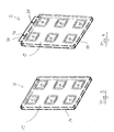
- FIGS. 3 and 4 each show a cladding panel 2 from the front, with a back in the assembled state of the Panel 2 of the wall 4 faces. Behind the of left visible surface material 14 is that of the wall 4th facing support material 16 with a total of six attached thereto flat first adhesive components 10 of the reversible Fastening device 8 shown.
- the surface material 14 is shown in FIG. 4 additionally with a Blechabkantung 30 equipped, the two openings 34 having. About these openings 34 is an additional Attaching the panel 2 to the wall 4 by means Screws 32, rivets and the like possible.
- the cladding 2 instead of as in Fig. 2 with a distance above the baseboard, directly on the skirting set and thereby additionally supported become.
Landscapes
- Engineering & Computer Science (AREA)
- Architecture (AREA)
- Civil Engineering (AREA)
- Structural Engineering (AREA)
- Mechanical Engineering (AREA)
- Cage And Drive Apparatuses For Elevators (AREA)
Applications Claiming Priority (2)
| Application Number | Priority Date | Filing Date | Title |
|---|---|---|---|
| DE200420001607 DE202004001607U1 (de) | 2004-01-29 | 2004-01-29 | Einrichtung zum Verkleiden einer Wand einer Aufzugskabine |
| DE202004001607U | 2004-01-29 |
Publications (2)
| Publication Number | Publication Date |
|---|---|
| EP1574471A2 true EP1574471A2 (fr) | 2005-09-14 |
| EP1574471A3 EP1574471A3 (fr) | 2006-12-20 |
Family
ID=32087882
Family Applications (1)
| Application Number | Title | Priority Date | Filing Date |
|---|---|---|---|
| EP04027822A Withdrawn EP1574471A3 (fr) | 2004-01-29 | 2004-11-24 | Dispositif pour décorer les mur d'une cabine d'ascenseur |
Country Status (2)
| Country | Link |
|---|---|
| EP (1) | EP1574471A3 (fr) |
| DE (1) | DE202004001607U1 (fr) |
Cited By (2)
| Publication number | Priority date | Publication date | Assignee | Title |
|---|---|---|---|---|
| DE202018102460U1 (de) | 2018-04-24 | 2018-05-14 | Andreas MADER | Wandvorrichtung für eine Aufzugkabine und Aufzugkabine mit einer solchen Wandvorrichtung |
| CN116692640A (zh) * | 2023-05-29 | 2023-09-05 | 杭州西奥电梯有限公司 | 一种侧后一段踢脚线的装潢轿厢 |
Families Citing this family (1)
| Publication number | Priority date | Publication date | Assignee | Title |
|---|---|---|---|---|
| CN103402902B (zh) * | 2011-03-04 | 2016-03-02 | 奥的斯电梯公司 | 电梯轿厢壁板 |
Family Cites Families (6)
| Publication number | Priority date | Publication date | Assignee | Title |
|---|---|---|---|---|
| US4430835A (en) * | 1981-08-20 | 1984-02-14 | Otis Elevator Company | Elevator cab |
| US4635756A (en) * | 1985-07-09 | 1987-01-13 | Westinghouse Electric Corp. | Elevator cab |
| KR920004224A (ko) * | 1990-08-29 | 1992-03-27 | 원본미기재 | 차량의 내장판의 설치방법 및 설치구조 |
| EP0867398A1 (fr) * | 1997-03-26 | 1998-09-30 | Inventio Ag | Eléments d'habillage et de décoration pour cabines d'ascenseur |
| JPH10338443A (ja) * | 1997-06-09 | 1998-12-22 | Hasekou Community:Kk | エレベータ壁面保護シート |
| JP2001220080A (ja) * | 2000-02-03 | 2001-08-14 | Hitachi Building Systems Co Ltd | エレベータの乗りかご用内装材の貼付構造 |
-
2004
- 2004-01-29 DE DE200420001607 patent/DE202004001607U1/de not_active Expired - Lifetime
- 2004-11-24 EP EP04027822A patent/EP1574471A3/fr not_active Withdrawn
Cited By (3)
| Publication number | Priority date | Publication date | Assignee | Title |
|---|---|---|---|---|
| DE202018102460U1 (de) | 2018-04-24 | 2018-05-14 | Andreas MADER | Wandvorrichtung für eine Aufzugkabine und Aufzugkabine mit einer solchen Wandvorrichtung |
| DE102018109773A1 (de) | 2018-04-24 | 2019-10-24 | Andreas MADER | Wandvorrichtung für eine Aufzugkabine und Aufzugkabine mit einer solchen Wandvorrichtung |
| CN116692640A (zh) * | 2023-05-29 | 2023-09-05 | 杭州西奥电梯有限公司 | 一种侧后一段踢脚线的装潢轿厢 |
Also Published As
| Publication number | Publication date |
|---|---|
| EP1574471A3 (fr) | 2006-12-20 |
| DE202004001607U1 (de) | 2004-04-01 |
Similar Documents
| Publication | Publication Date | Title |
|---|---|---|
| US4462193A (en) | Elevator cab | |
| DE102010027394A1 (de) | Befestigungssystem | |
| DE69817670T2 (de) | Wandstruktur | |
| NZ201618A (en) | Elevator cab with steel frame and expanded core plastic panels | |
| EP3112545A2 (fr) | Panneau acoustique | |
| DE69910051T2 (de) | Bodenplatte für fahrzeugboden | |
| EP2194208A1 (fr) | Support mural pour plaques de façades | |
| EP1574471A2 (fr) | Dispositif pour décorer les mur d'une cabine d'ascenseur | |
| DE69418981T2 (de) | Kammplatte für Rolltreppen oder Fahrsteige | |
| DE202019103716U1 (de) | Befestigungshardware für Fahrzeugstrukturen | |
| DE9406302U1 (de) | Verkleidungsteil für Fahrzeuge oder Flugzeuge | |
| DE202010013869U1 (de) | Innenausstattungselement für Fahrzeugkabinen | |
| DE19836030B4 (de) | Vorwandkonstruktion | |
| DE202012007754U1 (de) | Clip-, Stift- und Halterungsbaugruppe zur Befestigung von Zubehörteilen an Fahrzeugpaneelen | |
| DE60113565T2 (de) | Aufbau einer aufzugskabine und verfahren des aufbaus | |
| EP0867398A1 (fr) | Eléments d'habillage et de décoration pour cabines d'ascenseur | |
| DE102015105619A1 (de) | Flugzeugmodulverkleidungsvorrichtung | |
| DE202004001858U1 (de) | Profilleiste | |
| DE69420165T2 (de) | Abdichtung zwischen den Strukturen einer Schachttür und einer Mauer | |
| DE202022107213U1 (de) | Aufhängschiene sowie Herstellung einer integrierten Aufhängschiene | |
| DE3820684A1 (de) | Wandelement | |
| DE102009009987A1 (de) | Wandpaneele | |
| EP0859095B1 (fr) | Cloison ou plafond isolant acoustiquement, notamment pour l'utilisation dans la construction navale | |
| EP1903161B1 (fr) | Dispositif d'inspection comportant un cadre et une porte de visite | |
| DE69105380T2 (de) | Treppengeländer. |
Legal Events
| Date | Code | Title | Description |
|---|---|---|---|
| PUAI | Public reference made under article 153(3) epc to a published international application that has entered the european phase |
Free format text: ORIGINAL CODE: 0009012 |
|
| AK | Designated contracting states |
Kind code of ref document: A2 Designated state(s): AT BE BG CH CY CZ DE DK EE ES FI FR GB GR HU IE IS IT LI LU MC NL PL PT RO SE SI SK TR |
|
| AX | Request for extension of the european patent |
Extension state: AL HR LT LV MK YU |
|
| PUAL | Search report despatched |
Free format text: ORIGINAL CODE: 0009013 |
|
| AK | Designated contracting states |
Kind code of ref document: A3 Designated state(s): AT BE BG CH CY CZ DE DK EE ES FI FR GB GR HU IE IS IT LI LU MC NL PL PT RO SE SI SK TR |
|
| AX | Request for extension of the european patent |
Extension state: AL HR LT LV MK YU |
|
| RIC1 | Information provided on ipc code assigned before grant |
Ipc: E04F 13/08 20060101ALI20061116BHEP Ipc: B66B 11/02 20060101AFI20050715BHEP |
|
| AKX | Designation fees paid | ||
| STAA | Information on the status of an ep patent application or granted ep patent |
Free format text: STATUS: THE APPLICATION IS DEEMED TO BE WITHDRAWN |
|
| 18D | Application deemed to be withdrawn |
Effective date: 20070621 |
|
| REG | Reference to a national code |
Ref country code: DE Ref legal event code: 8566 |