EP1574471A2 - Elevator cab wall decoration arrangement - Google Patents
Elevator cab wall decoration arrangement Download PDFInfo
- Publication number
- EP1574471A2 EP1574471A2 EP04027822A EP04027822A EP1574471A2 EP 1574471 A2 EP1574471 A2 EP 1574471A2 EP 04027822 A EP04027822 A EP 04027822A EP 04027822 A EP04027822 A EP 04027822A EP 1574471 A2 EP1574471 A2 EP 1574471A2
- Authority
- EP
- European Patent Office
- Prior art keywords
- reversible fastening
- fastening device
- adhesive component
- panel
- wall
- Prior art date
- Legal status (The legal status is an assumption and is not a legal conclusion. Google has not performed a legal analysis and makes no representation as to the accuracy of the status listed.)
- Withdrawn
Links
Images


Classifications
-
- B—PERFORMING OPERATIONS; TRANSPORTING
- B66—HOISTING; LIFTING; HAULING
- B66B—ELEVATORS; ESCALATORS OR MOVING WALKWAYS
- B66B11/00—Main component parts of lifts in, or associated with, buildings or other structures
- B66B11/02—Cages, i.e. cars
- B66B11/0226—Constructional features, e.g. walls assembly, decorative panels, comfort equipment, thermal or sound insulation
-
- E—FIXED CONSTRUCTIONS
- E04—BUILDING
- E04F—FINISHING WORK ON BUILDINGS, e.g. STAIRS, FLOORS
- E04F13/00—Coverings or linings, e.g. for walls or ceilings
- E04F13/07—Coverings or linings, e.g. for walls or ceilings composed of covering or lining elements; Sub-structures therefor; Fastening means therefor
- E04F13/08—Coverings or linings, e.g. for walls or ceilings composed of covering or lining elements; Sub-structures therefor; Fastening means therefor composed of a plurality of similar covering or lining elements
- E04F13/088—Coverings or linings, e.g. for walls or ceilings composed of covering or lining elements; Sub-structures therefor; Fastening means therefor composed of a plurality of similar covering or lining elements fixed directly to the wall by means of magnets, hook and loop-type or similar fasteners, not necessarily involving the side faces of the covering element
-
- B—PERFORMING OPERATIONS; TRANSPORTING
- B66—HOISTING; LIFTING; HAULING
- B66B—ELEVATORS; ESCALATORS OR MOVING WALKWAYS
- B66B19/00—Mining-hoist operation
- B66B19/007—Mining-hoist operation method for modernisation of elevators
Definitions
- the present invention relates to a device for Covering areas in the area of a lift, a cladding for a wall of a cabin of a lift, one Wall for an elevator car and an elevator car.
- Walls of elevator cabins or cars are in elevators For people and / or loads usually made of sheet metal.
- the insides of the cars of elevators for persons or Loads are therefore very often disguises, i.
- Side and rear walls of the cabs are by area Covered panels, as well as the cabin ceilings and the floor-facing surfaces of doors and door frames.
- the object of the invention is an equipment of walls for elevator cars with fairings, so the possibility a covering of such walls, to improve.
- the Invention should u.a. an assembly of panels of such Walls are both simplified and cheaper be.
- walls for elevator cabins be more advantageous overall equip, so that for example, also technical advantages for an operation of an elevator installation, in which the elevator car drives, surrendered.
- This task comes with a feature with the features of claim 1, a panel with the features of claim 18, a wall with the features of Patent claim 19 and an elevator car with the features of claim 20 solved.
- the inventive device for dressing surfaces in the area of elevators has at least one fairing and at least one of two interacting, planar ones Adhesive components formed reversible fastening device on.
- a first adhesive component the at least one reversible fastening device the cladding and in each case a second adhesive component of at least one reversible fastening device on the arranged to be covered area.
- the at least one reversible fastening device as a flexible or flexible pressure sealing strip is formed or are.
- the reversible fastening device is therefore as a so-called Velcro closure or Surface adhesive closure with tentacle adhesive or with e.g. Hemispherical head formed.
- Such reversible fastening devices have the advantage that through them, so by means of the two interacting adhesive components between the panel and the wall, a secure connection quick and easy to prepare as well as uncomplicated Non-destructive manner is releasable again.
- the one adhesive component is fixed to the back the cladding panel connected, e.g. glued, screwed, riveted or welded, and the other with the one to be clad Area.
- the inventive Facility offers the possibility of a fast and uncomplicated optical change of the elevator car.
- On individual customer wishes concerning the equipment can be independent of a technical embodiment of the Raw cabin or an existing, to be modernized Elevator cab flexible, easy and efficient become. In the latter case, it is only necessary to the existing wall, the second planar adhesive components to arrange the reversible fastening device.
- the two adhesive components of the at least one reversible Fastening device can on the one hand different Have structures. So can one of the two adhesive components a plurality of surface arranged, preferably eyelet or loop-like engagement means for the reversible, easily detachable hook or tentacle hooking device which are attached to the second adhesive component in one of the plurality of engagement means largely corresponding Number are arranged flat.
- the flexible pressure closure with on both Pages of essentially similar individual structures, such as. with hemispherical heads on a short stem, e.g. Dual lock.
- the flexible pressure closure self-adhesive, so that on the one Side of each adhesive component the hemisphere heads and on the On the other side of each adhesive component an adhesive is arranged is with which the component on the trim panel or is glued to the surface to be covered.
- the first adhesive component is at least a reversible fastening device on the panel and the second adhesive component of the at least one reversible Fastening device on the wall of the elevator car glued.
- the panel provided several reversible fastening devices, so these are preferably evenly spaced under symmetric, regular alignment between the wall and the paneling arranged.
- the first and the second adhesive component each of a reversible fastening device are thus congruent or mirror image both on the cladding and on the wall attached.
- With appropriate arrangement of the reversible fastening devices is it possible, for example, disguises on the wall of the elevator car both horizontally and also to arrange vertically or attach.
- With the reversible Fastener is between the panel and provided a secure, externally invisible connection to the wall.
- the at least one panel of a Carrier material and at least one adhered thereto Surface material is formed.
- the surface material is preferably as a stainless steel sheet educated.
- edible metals such as any Stainless steel textured sheets can be used.
- the surface material may also be made of plastic, textile material, Wood and the like or as a mirror be educated. Accordingly, for this surface material depending on optical, customer-specific requirements any suitable, for example, also flame retardant Material to be selected.
- the support material can be particularly advantageous as metallic Lightweight board, in particular as an aluminum lightweight board, be educated.
- This lightweight board consists of e.g. consisting of two cover sheets and one in between Sheet metal, the periodically repeating deformations and thus wavy or possibly zigzag is trained.
- the carrier material thus advantageously has a sandwich or honeycomb-like structure.
- This structure has to Advantage that this substrate is particularly light, thin-walled and also resistant to bending. Due to the small thickness the device according to the invention is the base of the Elevator car only slightly affected.
- the overall weight of the elevator car is substantially reduced compared to elevator cabins with conventional cowling equipment.
- a significant weight saving can be achieved with the device according to the invention, which makes it possible, for example, to use a smaller counterweight and thus also a smaller drive for the elevator.
- the low mass of the panel favors the assembly or disassembly of the panel, since the parts to be handled are considerably lighter than previous panels.
- the device according to the invention is a modular Equipment for interior walls, ie side and / or rear walls possible from elevator cabins. It lends itself here, two adjacent panels so relative to each other, preferably parallel to each other, relative to the wall of the elevator car to arrange that between these panels due to a spacing of these panels a Shadow gap arises. Depending on the optical requirements can in a region of this shadow gap on the wall a stainless steel strip or a, for example, black plastic strip be glued on. With the device according to the invention is It is possible to take into account a width of the shadow gap a division, for example, a panel-like trained Surface material to vary as desired. An advantageous Shadow gap width is about 8 mm, but can also only 3 mm.
- the shadow gap can also be used to attach a handrail or other cabin fixtures directly on the wall too allow to work without the panel in addition to have to.
- the elevator car is an insert of a skirting board conceivable on which the panel during assembly is to be set up.
- the wall of the elevator car or car of the elevator is usually formed of sheet metal wall slats. Because the Fastening of the cladding eg. Of cladding panels through the flexible pressure lock and this e.g. in relation to double-sided tape a considerably greater intrinsic thickness often, e.g. about 4 mm, can the division the cladding panels regardless of a classification of Wall lamellae are made without any attachment problems gives.
- the lining according to the invention for a wall of an elevator car each has a first planar adhesive component at least one of two interacting, planar Adhesive components formed reversible fastening device on.
- a first planar adhesive component with a each second planar adhesive component of the at least a reversible attachment device attached to the wall is arranged to connect.
- the respective second planar adhesive component with a respective first planar adhesive component of at least a reversible fastening device, which on a Cladding is arranged to connect.
- the inventive Wall for the elevator car is in a simple way equipped with one or more panels.
- the elevator car according to the invention with a number of Walls are provided that on at least one of the walls at least one second area adhesive component at least one of two cooperating, flat adhesive components trained reversible fastening device arranged is.
- a respective first surface adhesive component the reversible fastening device, which at a Cladding is arranged, with each second flat Bonding component to connect.
- the elevator car according to the invention or Rohkabine for a lift can thus under little effort according to individual requirements with a or more side by side facing panels be equipped or even with several against each other exchangeable cladding panels for e.g. one Car in blue or stainless steel.
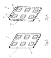
- Figure 1 shows a schematic representation of a horizontal Section through two mutually perpendicular, preferably formed from wall panels walls 4 of an elevator car 6. On these walls 4 are for dressing or to the equipment of the walls 4 or at least partially Cover the walls 4 panels 2 arranged or attached. On one of the two walls is also a Mirror 26 arranged or attached. A handrail 27 is via a handrail fastening 29 in the area of a shadow gap 24 between two panels 2 directly on the wall. 4 attached. In the sense of an advantageous figurative representation are the panels 2, the walls 4 and the Mirror 26 and the handrail 27 shortened, ie in the plane of the drawing cut, pictured.
- the panels 2 are made of a carrier material 16, in particular Metal or aluminum lightweight panels as well on it glued surface material 14, eg. Of stainless steel educated.
- a compound of the panels 2 with the wall 4 or a Attachment of the panels 2 on the walls 4 is about reversible fastening devices 8, so flexible Ziplock strips, Dual Lock, or Velcro closures provided. Details of advantageous embodiments the panels 2 and the reversible fastening devices 8 are shown in the following figures.
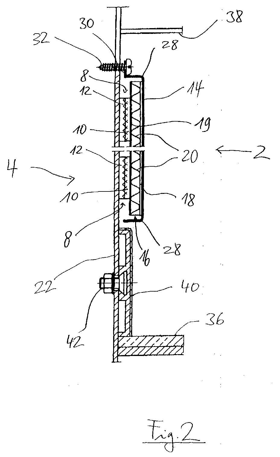
- FIG. 2 in a schematic representation in a vertical Section through a car wall 4 with indicated below Car floor 36 and above indicated car ceiling 38 and below directly above the car floor 36 with a Screw 42 fixed skirting 40 shows are the reversible Fasteners 8 of two with each other cooperating, flat adhesive components 10, 12 are formed. It is envisaged that a first planar adhesive component 10 each on one of the panels 2 and a second planar adhesive component 12 of the reversible fastening device 8 each attached to the wall 4 or glued is.
- a device thus comprises at least a panel 2 with a first attached thereto flat Adhesive component 10 of the reversible fastening device 8 and the cooperating second planar Adhesive component 12 of the reversible fastening device 8th.
- FIG. 1 is further shown that the panels 2 spaced apart, providing Shadow joints 24 are arranged parallel to each other. ever according to requirements regarding a design of the elevator car 6, the panels 2 on the walls 4 below arranged vertically or horizontally be. In the area of shadow gaps 24 may vary depending on the optical Requirements Stainless steel strip, eg black Plastic strips or alternatively black or metallic Color coatings, be arranged or applied.
- Stainless steel strip eg black Plastic strips or alternatively black or metallic Color coatings, be arranged or applied.
- a mirror 26 is alternative to the panel 2 on the wall 4 via reversible Attachment 8 a mirror 26 attached.
- Fig. 2 In addition to those already described in more detail, from two flat Adhesive components 10, 12 existing reversible fastening devices are in Fig. 2 also more details to a structure of the panel 2 shown.
- the Support material or the lightweight board 16 consists of two Cover plates 18, 19 passing through a between the two cover plates 18, 19 arranged wave-shaped plate 20 from each other are spaced.
- finished surface material 14 is on the cover plate 18 glued or in any other suitable manner attached. Accordingly, the respective first adhesive component 10 of the reversible fastening device on the of Wall 4 facing cover 19 of the lightweight panel 16 glued or attached.
- the surface material 14 may be at one or more edges Have bends 28. Thus it is achieved that the Lightweight panel 16 by the thus angled at the edges Surface material 14 completely covered as needed is.
- the low mass of the panel 2 further favors the assembly or disassembly of the panel 2 to the or from the wall 4, so that such operations by a person can be carried out under little effort.
- the substrate 16 all kinds of plates can be used or it can be the surface material 14 with sufficient inherent stability also directly with the reversible fastening devices 10, 12 on the wall 4 be attached.
- FIGS. 3 and 4 each show a cladding panel 2 from the front, with a back in the assembled state of the Panel 2 of the wall 4 faces. Behind the of left visible surface material 14 is that of the wall 4th facing support material 16 with a total of six attached thereto flat first adhesive components 10 of the reversible Fastening device 8 shown.
- the surface material 14 is shown in FIG. 4 additionally with a Blechabkantung 30 equipped, the two openings 34 having. About these openings 34 is an additional Attaching the panel 2 to the wall 4 by means Screws 32, rivets and the like possible.
- the cladding 2 instead of as in Fig. 2 with a distance above the baseboard, directly on the skirting set and thereby additionally supported become.
Landscapes
- Engineering & Computer Science (AREA)
- Architecture (AREA)
- Civil Engineering (AREA)
- Structural Engineering (AREA)
- Mechanical Engineering (AREA)
- Cage And Drive Apparatuses For Elevators (AREA)
Abstract
Die vorliegende Erfindung betrifft eine Einrichtung zum
Verkleiden von Flächen (4) im Bereich von Aufzügen, eine
Verkleidung (2) für diese Flächen (4) sowie die Aufzugkabine
(6). Es ist vorgesehen, daß ein Verkleiden der Flächen
durch die Verkleidung (2) mittels reversibler Befestigungseinrichtungen
(8), die aus jeweils zwei flächigen zusammenwirkenden
Haftkomponenten (10, 12) ausgebildet sind, realisiert
ist. Dabei ist jeweils eine erste Haftkomponente (10)
an der Verkleidung (2) und eine zweite Haftkomponente (12)
an der Wand (4) angeordnet.
Description
Die vorliegende Erfindung betrifft eine Einrichtung zum Verkleiden von Flächen im Bereich eines Aufzugs, eine Verkleidung für eine Wand einer Kabine eines Aufzugs, eine Wand für eine Aufzugkabine sowie eine Aufzugkabine.The present invention relates to a device for Covering areas in the area of a lift, a cladding for a wall of a cabin of a lift, one Wall for an elevator car and an elevator car.
Wände von Aufzugkabinen oder Fahrkörben sind bei Aufzügen für Personen und/oder Lasten meist aus Blech hergestellt. Die Innenseiten der Fahrkörbe von Aufzügen für Personen oder Lasten weisen daher sehr oft Verkleidungen auf, d.h. Seiten- und Rückwände der Fahrkabinen sind durch flächige Verkleidungen abgedeckt, ebenso wie die Kabinendecken und die zum Stockwerk weisenden Flächen der Türen und Türumrandungen.Walls of elevator cabins or cars are in elevators For people and / or loads usually made of sheet metal. The insides of the cars of elevators for persons or Loads are therefore very often disguises, i. Side and rear walls of the cabs are by area Covered panels, as well as the cabin ceilings and the floor-facing surfaces of doors and door frames.
Dabei ist z.B. bei Personenaufzügen in Gebäuden zu beachten, daß das Erscheinungsbild derartiger Verkleidungen an die Architektur des Gebäudes angepaßt ist. Was dieses Aussehen betrifft, sind zumeist unterschiedliche kundenspezifische Anforderungen zu erfüllen. Entsprechend unterschiedlich sind die Verkleidungen auszugestalten. Außerdem muß die Möglichkeit bestehen, Wände für Aufzugkabinen und die Eingangsbereiche mit jeweils angepaßten Verkleidungen auszustatten.In this case, e.g. in passenger lifts in buildings, that the appearance of such panels on the architecture of the building is adapted. What this look are mostly different customer specific To meet requirements. Accordingly different The panels have to be designed. In addition, must the possibility exist walls for elevator cabins and the Equip entrance areas with each adapted cladding.
Dabei gibt es grundsätzlich zwei Möglichkeiten der Verkleidung von z.B. Fahrkorb-Blechwänden. Zum einen kann direkt auf die Blechwand eine Verkleidung aufgeklebt werden, z.B. dünnes Edelstahlblech oder eine Kunststoffplatte oder -folie und zum anderen kann man auf der zu verkleidenden Seite der Blechwände zusätzlich Verkleidungsplatten mit der gewünschten Oberfläche anordnen und befestigen. Dabei hat die zweite Verbindungsart den Vorteil, daß durch die zusätzlichen Platten auch eine Geräusch- und/oder Temperaturdämmung erfolgen kann.There are basically two ways of disguise from e.g. Car sheet metal walls. For one thing, directly a cladding is adhered to the sheet metal wall, e.g. thin stainless steel sheet or a plastic plate or film and on the other hand you can on the to be disguised Side of the sheet metal walls in addition cladding panels with the Arrange and secure desired surface. It has the second type of connection has the advantage that by the additional Plates also a noise and / or temperature insulation can be done.
Bisher wurden für diese zusätzlichen aufgesetzten Verkleidungen der Fahrkörbe schwere, aufwendig einzuhängende Fahrkorbpaneele verwendet. Diese Fahrkorbpaneele sind bspw. als Preßspanplatten mit einem Gegenzugblech und Verkleidungsblechen aus Edelstahl ausgebildet. Die Fahrkorbpaneele werden mittels Paneelhaltern an Wandlamellen von Rohkabinen von Aufzügen eingehängt. Dies hat unter anderem zur Folge, daß durch eine derartige Verkleidung eine lichte Breite der Aufzugkabine um ca. 40 mm und eine lichte Tiefe der Aufzugkabine um ca. 20 mm verringert wird.So far have been for these additional patch panels the cars heavy, consuming to be hitched car panels used. These car panels are, for example, as Chipboard with a counter-plate and cladding sheets made of stainless steel. The car panels will be by means of panel holders on wall lamellae of raw cabins hung by elevators. This has, among other things, that by such a fairing a clear width of the Elevator car about 40 mm and a clear depth of the elevator car is reduced by about 20 mm.
Aufgabe der Erfindung ist es, eine Ausstattung von Wänden für Aufzugkabinen mit Verkleidungen, also die Möglichkeit eines Verkleidens derartiger Wände, zu verbessern. Mit der Erfindung soll u.a. eine Montage von Verkleidungen derartiger Wände sowohl vereinfacht werden als auch kostengünstiger sein. Mit der Erfindung sollen Wände für Aufzugkabinen insgesamt vorteilhafter auszustatten sein, so daß sich bspw. auch technische Vorteile für einen Betrieb einer Aufzuganlage, in der die Aufzugkabine fährt, ergeben.The object of the invention is an equipment of walls for elevator cars with fairings, so the possibility a covering of such walls, to improve. With the Invention should u.a. an assembly of panels of such Walls are both simplified and cheaper be. With the invention, walls for elevator cabins be more advantageous overall equip, so that for example, also technical advantages for an operation of an elevator installation, in which the elevator car drives, surrendered.
Diese Aufgabe wird mit einer Einrichtung mit den Merkmalen
des Patentanspruchs 1, einer Verkleidung mit den Merkmalen
des Patentanspruchs 18, einer Wand mit den Merkmalen des
Patentanspruchs 19 sowie einer Aufzugkabine mit den Merkmalen
des Patentanspruchs 20 gelöst. This task comes with a feature with the features
of claim 1, a panel with the features
of
Die erfindungsgemäße Einrichtung zum Verkleiden von Flächen im Bereich von Aufzügen weist wenigstens eine Verkleidung und mindestens eine aus zwei zusammenwirkenden, flächigen Haftkomponenten ausgebildete reversible Befestigungseinrichtung auf. Dabei ist jeweils eine erste Haftkomponente der mindestens einen reversiblen Befestigungseinrichtung an der Verkleidung und jeweils eine zweite Haftkomponente der mindestens einen reversiblen Befestigungseinrichtung an der zu verkleidenden Fläche angeordnet. Zum Anhängen der Verkleidung an die zu verkleidende Fläche sind die beiden Haftkomponenten lösbar miteinander zu verbinden. Mit der erfindungsgemäßen Einrichtung ist eine einfach durchführbare Montage für eine flexible Ausstattung von Flächen in und vor Aufzugkabinen mit Verkleidungen realisierbar. Bevorzugt ist die Erfindung für die Innenauskleidung von Aufzugkabinen zu verwenden.The inventive device for dressing surfaces in the area of elevators has at least one fairing and at least one of two interacting, planar ones Adhesive components formed reversible fastening device on. In each case, a first adhesive component the at least one reversible fastening device the cladding and in each case a second adhesive component of at least one reversible fastening device on the arranged to be covered area. To attach the panel to the surface to be covered are the two Releasably bond adhesive components together. With the Device according to the invention is an easy to carry out Assembly for a flexible equipment of surfaces in and before elevator cabins with cladding feasible. Prefers is the invention for the inner lining of elevator cabins to use.
In bevorzugter Ausgestaltung der Erfindung ist vorgesehen, daß zumindest eine, insbesondere beide, flächige Haftkomponenten der mindestens einen reversiblen Befestigungseinrichtung als flexibler bzw. flexible Druckverschlußstreifen ausgebildet ist bzw. sind. Die reversible Befestigungseinrichtung ist demnach als sogenannter Klettverschluß bzw. Flächen-Haftverschluß mit Tentakel-Haftmittel oder mit z.B. Halbkugelköpfchen ausgebildet. Derartige reversible Befestigungseinrichtungen haben den Vorteil, daß durch sie, also mittels der beiden zusammenwirkenden Haftkomponenten zwischen der Verkleidung und der Wand, eine sichere Verbindung schnell und einfach bereitstellbar sowie auf unkomplizierte Weise zerstörungsfrei wieder lösbar ist.In a preferred embodiment of the invention is provided that at least one, in particular both, surface adhesive components the at least one reversible fastening device as a flexible or flexible pressure sealing strip is formed or are. The reversible fastening device is therefore as a so-called Velcro closure or Surface adhesive closure with tentacle adhesive or with e.g. Hemispherical head formed. Such reversible fastening devices have the advantage that through them, so by means of the two interacting adhesive components between the panel and the wall, a secure connection quick and easy to prepare as well as uncomplicated Non-destructive manner is releasable again.
Dabei wird die eine Haftkomponente fest mit der Rückseite der Verkleidungsplatte verbunden, z.B. geklebt, geschraubt, genietet oder geschweißt, und die andere mit der zu verkleidenden Fläche. Durch die sich erfindungsgemäß ergebende einfache Montage und den Umstand, daß eine Rohkabine des Aufzugs zunächst ohne weitere Berücksichtigung einer Ausgestaltung von der Verkleidung gefertigt werden kann, ist es möglich, das Design der Verkleidung der Wand und somit der Aufzugkabine auch nach einem Einbau der Aufzugkabine zu bestimmen oder zu ändern.The one adhesive component is fixed to the back the cladding panel connected, e.g. glued, screwed, riveted or welded, and the other with the one to be clad Area. By inventively resulting simple assembly and the fact that a raw cabin of the Elevator initially without further consideration of an embodiment can be made of the panel is It is possible to design the cladding of the wall and thus the elevator car also after installation of the elevator car to determine or change.
Besonders für den Bereich der Modernisierung bietet die erfindungsgemäße Einrichtung die Möglichkeit einer schnellen und unkomplizierten optischen Veränderung der Aufzugkabine. Auf individuelle Kundenwünsche bezüglich der Ausstattung kann unabhängig von einer technischen Ausgestaltung der Rohkabine oder einer bereits vorhandenen, zu modernisierenden Aufzugkabine flexibel, einfach und effizient reagiert werden. Im letzteren Fall ist es lediglich erforderlich, an der vorhandenen Wand die jeweils zweiten flächigen Haftkomponenten der reversiblen Befestigungseinrichtung anzuordnen.Especially for the field of modernization offers the inventive Facility the possibility of a fast and uncomplicated optical change of the elevator car. On individual customer wishes concerning the equipment can be independent of a technical embodiment of the Raw cabin or an existing, to be modernized Elevator cab flexible, easy and efficient become. In the latter case, it is only necessary to the existing wall, the second planar adhesive components to arrange the reversible fastening device.
Mit der erfindungsgemäßen Einrichtung ist ein schneller Austausch von Verkleidungen für Wände von Aufzugkabinen möglich, ohne daß dabei der Aufzug außer Betrieb genommen werden muß. Dies bietet sich bspw. auch dann an, wenn die Verkleidung aufgrund von Abnutzungserscheinungen beschädigt, also defekt oder zerkratzt sein sollte.With the device according to the invention is a faster Replacement of cladding for walls of elevator cabins possible without taking the elevator out of service must become. This is useful, for example, even if the Cladding damaged due to signs of wear, so it should be broken or scratched.
Die beiden Haftkomponenten der mindestens einen reversiblen Befestigungseinrichtung können zum einen unterschiedliche Strukturen aufweisen. So kann die eine der beiden Haftkomponenten eine Vielzahl flächig angeordneter, vorzugsweise ösen- oder schlingenartiger Eingriffmittel zur reversiblen, leicht lösbaren Aufnahme haken- oder tentakelförmiger Einhakmittel aufweisen, die an der zweiten Haftkomponente in einer der Vielzahl der Eingriffmittel weitgehend entsprechenden Anzahl flächig angeordnet sind. The two adhesive components of the at least one reversible Fastening device can on the one hand different Have structures. So can one of the two adhesive components a plurality of surface arranged, preferably eyelet or loop-like engagement means for the reversible, easily detachable hook or tentacle hooking device which are attached to the second adhesive component in one of the plurality of engagement means largely corresponding Number are arranged flat.
Bei einer Montage zur Befestigung der Verkleidung an der Wand haken sich oder greifen die Einhakmittel in die Eingriffmittel ein. Ist vorgesehen, die Verkleidung auszutauschen, so kann die Verbindung zwischen der Verkleidung und der Wand unter Aufbringung einer hinreichend großen Kraft zerstörungsfrei gelöst werden.In a mounting for attaching the panel to the Wall hook or grip the hooking means in the engaging means one. Is intended to replace the panel, so can the connection between the panel and the wall with the application of a sufficiently large force be solved nondestructively.
Ebenso gibt es diesen flexiblen Druckverschluß mit auf beiden Seiten im wesentlichen gleichartigen Einzelstrukturen, wie z.B. mit Halbkugelköpfchen auf einem kurzen Stamm, z.B. Dual Lock. Vorteilhafterweise ist der flexible Druckverschluß selbstklebend ausgerüstet, so daß auf der einen Seite jeder Haftkomponente die Halbkugelköpfe und auf der anderen Seite jeder Haftkomponente ein Kleber angeordnet ist, mit dem die Komponente an der Verkleidungsplatte oder an der zu verkleidenden Fläche anklebbar ist.Likewise, there is this flexible pressure closure with on both Pages of essentially similar individual structures, such as. with hemispherical heads on a short stem, e.g. Dual lock. Advantageously, the flexible pressure closure self-adhesive, so that on the one Side of each adhesive component the hemisphere heads and on the On the other side of each adhesive component an adhesive is arranged is with which the component on the trim panel or is glued to the surface to be covered.
Des weiteren ist die erste Haftkomponente der mindestens einen reversiblen Befestigungseinrichtung auf der Verkleidung und die zweite Haftkomponente der mindestens einen reversiblen Befestigungseinrichtung auf der Wand der Aufzugkabine aufgeklebt. Sind zur Befestigung der Verkleidung an der Wand mehrere reversible Befestigungseinrichtungen vorgesehen, so sind diese vorzugsweise in gleichmäßigen Abständen unter symmetrischer, regelmäßiger Ausrichtung zwischen der Wand und der Verkleidung angeordnet. Die erste und die zweite Haftkomponente jeweils einer reversiblen Befestigungseinrichtung sind somit deckungsgleich bzw. spiegelbildlich sowohl an der Verkleidung als auch an der Wand befestigt. Bei entsprechender Anordnung der reversiblen Befestigungseinrichtungen ist es bspw. möglich, Verkleidungen an der Wand der Aufzugkabine sowohl horizontal als auch vertikal anzuordnen bzw. anzubringen. Mit der reversiblen Befestigungseinrichtung wird zwischen der Verkleidung und der Wand eine sichere, äußerlich unsichtbare Verbindung bereitgestellt.Furthermore, the first adhesive component is at least a reversible fastening device on the panel and the second adhesive component of the at least one reversible Fastening device on the wall of the elevator car glued. Are to attach the panel the wall provided several reversible fastening devices, so these are preferably evenly spaced under symmetric, regular alignment between the wall and the paneling arranged. The first and the second adhesive component each of a reversible fastening device are thus congruent or mirror image both on the cladding and on the wall attached. With appropriate arrangement of the reversible fastening devices is it possible, for example, disguises on the wall of the elevator car both horizontally and also to arrange vertically or attach. With the reversible Fastener is between the panel and provided a secure, externally invisible connection to the wall.
In weiterer vorteilhafter Ausgestaltung der Erfindung ist vorgesehen, daß die wenigstens eine Verkleidung aus einem Trägermaterial und zumindest einem darauf aufgeklebten Oberflächenmaterial ausgebildet ist.In a further advantageous embodiment of the invention provided that the at least one panel of a Carrier material and at least one adhered thereto Surface material is formed.
Das Oberflächenmaterial ist bevorzugt als Edelstahlblech ausgebildet. Hierfür sind z.B. kantbare Metalle wie beliebige Edelstahl-Strukturbleche einsetzbar. Selbstverständlich kann das Oberflächenmaterial auch aus Kunststoff, Textilmaterial, Holz und dergleichen oder auch als Spiegel ausgebildet sein. Für dieses Oberflächenmaterial kann demnach je nach optischen, kundenspezifischen Anforderungen ein beliebiges geeignetes, bspw. auch schwer entflammbares Material gewählt werden.The surface material is preferably as a stainless steel sheet educated. For this purpose, e.g. edible metals such as any Stainless steel textured sheets can be used. Of course the surface material may also be made of plastic, textile material, Wood and the like or as a mirror be educated. Accordingly, for this surface material depending on optical, customer-specific requirements any suitable, for example, also flame retardant Material to be selected.
Das Trägermaterial kann dabei besonders vorteilhaft als metallische Leichtbauplatte, insbesondere als Aluminium-Leichtbauplatte, ausgebildet sein. Diese Leichtbauplatte besteht z.B. aus zwei Deckblechen und einem dazwischen angeordneten Blech, das sich periodisch wiederholende Verformungen aufweist und demnach wellen- oder eventuell zickzackförmig ausgebildet ist.The support material can be particularly advantageous as metallic Lightweight board, in particular as an aluminum lightweight board, be educated. This lightweight board consists of e.g. consisting of two cover sheets and one in between Sheet metal, the periodically repeating deformations and thus wavy or possibly zigzag is trained.
Das Trägermaterial weist also vorteilhafterweise eine sandwich- bzw. wabenartige Struktur auf. Dieser Aufbau hat zum Vorteil, daß dieses Trägermaterial besonders leicht, dünnwandig und zudem biegesteif ist. Durch die geringe Dicke der erfindungsgemäßen Einrichtung wird die Grundfläche der Aufzugkabine nur geringfügig beeinflußt.The carrier material thus advantageously has a sandwich or honeycomb-like structure. This structure has to Advantage that this substrate is particularly light, thin-walled and also resistant to bending. Due to the small thickness the device according to the invention is the base of the Elevator car only slightly affected.
Aufgrund der sich somit ergebenden geringen Masse der Verkleidung aus dem Trägermaterial und dem Oberflächenmaterial, die ungefähr 11 kg/m2 beträgt, ist das Gesamtgewicht der Aufzugkabine im Vergleich zu Aufzugkabinen mit herkömmlichen Verkleidungseinrichtungen wesentlich reduzierbar. Bei einer Aufzugkabine mit einer Masse von z.B. 1.000 kg ist mit der erfindungsgemäßen Einrichtung eine deutliche Gewichtsersparnis zu erreichen, wodurch es z.B. möglich ist, ein kleineres Gegengewicht und somit auch einen kleineren Antrieb für den Aufzug zu verwenden. Außerdem begünstigt die geringe Masse der Verkleidung die Montage oder Demontage der Verkleidung, da die zu handhabenden Teile erheblich leichter sind als bisherige Verkleidungsplatten.Due to the resulting low mass of the substrate and surface material covering, which is approximately 11 kg / m 2 , the overall weight of the elevator car is substantially reduced compared to elevator cabins with conventional cowling equipment. In an elevator car with a mass of, for example, 1,000 kg, a significant weight saving can be achieved with the device according to the invention, which makes it possible, for example, to use a smaller counterweight and thus also a smaller drive for the elevator. In addition, the low mass of the panel favors the assembly or disassembly of the panel, since the parts to be handled are considerably lighter than previous panels.
Mit der erfindungsgemäßen Einrichtung ist eine modulare Ausstattung für Innenwände, also Seiten- und/oder Rückwände von Aufzugkabinen möglich. Es bietet sich hierbei an, zwei benachbarte Verkleidungen derart relativ zueinander, vorzugsweise parallel zueinander, relativ zu der Wand der Aufzugkabine anzuordnen, daß zwischen diesen Verkleidungen aufgrund einer Beabstandung dieser Verkleidungen eine Schattenfuge entsteht. Je nach optischen Anforderungen kann in einem Bereich dieser Schattenfuge auf der Wand ein Edelstahlstreifen oder ein bspw. schwarzer Kunststoffstreifen aufgeklebt sein. Mit der erfindungsgemäßen Einrichtung ist es möglich, eine Breite der Schattenfuge unter Berücksichtigung einer Aufteilung bspw. paneelartig ausgebildetem Oberflächenmaterial beliebig zu variieren. Eine vorteilhafte Schattenfugenbreite beträgt ca. 8 mm, kann jedoch auch nur 3 mm betragen. Durch eine geeignete auftragbare Farbbeschichtung auf der Wand im Bereich der Schattenfuge in schwarz oder silber ist ebenfalls eine vorteilhafte optische Ausgestaltung der Schattenfuge unter zusätzlicher Reduzierung des Montageaufwands erreichbar. Die Schattenfuge kann auch benutzt werden, um die Befestigung eines Handlaufs oder anderer Kabineneinbauten direkt auf der Wand zu ermöglichen, ohne die Verkleidung zusätzlich bearbeiten zu müssen.With the device according to the invention is a modular Equipment for interior walls, ie side and / or rear walls possible from elevator cabins. It lends itself here, two adjacent panels so relative to each other, preferably parallel to each other, relative to the wall of the elevator car to arrange that between these panels due to a spacing of these panels a Shadow gap arises. Depending on the optical requirements can in a region of this shadow gap on the wall a stainless steel strip or a, for example, black plastic strip be glued on. With the device according to the invention is It is possible to take into account a width of the shadow gap a division, for example, a panel-like trained Surface material to vary as desired. An advantageous Shadow gap width is about 8 mm, but can also only 3 mm. By a suitable coatable color coating on the wall in the area of the shadow gap in black or silver is also an advantageous optical Design of the shadow gap with additional reduction of the installation effort achievable. The shadow gap Can also be used to attach a handrail or other cabin fixtures directly on the wall too allow to work without the panel in addition to have to.
Optional ist in der Aufzugkabine ein Einsatz einer Sockelleiste denkbar, auf die die Verkleidung bei der Montage aufzusetzen ist.Optionally, in the elevator car is an insert of a skirting board conceivable on which the panel during assembly is to be set up.
Die Wand der Aufzugkabine bzw. des Fahrkorbs des Aufzugs ist üblicherweise aus Blechwandlamellen gebildet. Da die Befestigung der Verkleidung bspw. von Verkleidungsplatten durch den flexiblen Druckverschluß erfolgt und dieser z.B. im Verhältnis zu Doppelklebeband eine erheblich größere Eigendicke aufweist, oft z.B. ca. 4 mm, kann die Einteilung der Verkleidungsplatten unabhängig von einer Einteilung der Wandlamellen erfolgen, ohne daß es Befestigungsprobleme gibt.The wall of the elevator car or car of the elevator is usually formed of sheet metal wall slats. Because the Fastening of the cladding eg. Of cladding panels through the flexible pressure lock and this e.g. in relation to double-sided tape a considerably greater intrinsic thickness often, e.g. about 4 mm, can the division the cladding panels regardless of a classification of Wall lamellae are made without any attachment problems gives.
Durch die Maßnahme, für die erfindungsgemäße Einrichtung reversible Befestigungseinrichtungen, also flexible Druckverschlußstreifen bzw. Klettverschlüsse zu wählen, werden möglicherweise an der Wand vorhandene Unebenheiten, bspw. zwischen zwei nebeneinander angeordneten Wandlamellen in einfacher Weise ausgeglichen. Dies ergibt sich deshalb, weil durch die zwischen der Wand und der Verkleidung angeordneten reversiblen Befestigungseinrichtungen zwischen der Wand und der Verkleidung ein gewisser Abstand vorhanden ist.By the measure, for the inventive device reversible fastening devices, so flexible pressure sealing strip or Velcro closures are to be possibly on the wall existing bumps, eg. between two adjacent wall slats in balanced in a simple way. This is why because arranged by the between the wall and the panel reversible fastening devices between the Wall and the panel a certain distance available is.
Zudem wird mit der erfindungsgemäßen Einrichtung im Vergleich zu unverkleideten Wänden von Aufzugkabinen eine verbesserte Geräuschisolation realisiert.In addition, with the device according to the invention in comparison to unclad walls of elevator cabins an improved Noise isolation realized.
Die erfindungsgemäße Verkleidung für eine Wand einer Aufzugkabine weist jeweils eine erste flächige Haftkomponente mindestens einer aus zwei zusammenwirkenden, flächigen Haftkomponenten ausgebildeten reversiblen Befestigungseinrichtung auf. Zur Anbringung der Verkleidung an der Wand ist die jeweils eine erste flächige Haftkomponente mit einer jeweils zweiten flächigen Haftkomponente der mindestens einen reversiblen Befestigungseinrichtung, die an der Wand angeordnet ist, zu verbinden. Mit dieser erfindungsgemäßen Verkleidung ist eine einfache, flexibel bereitstellbare Ausstattung der Aufzugkabine möglich.The lining according to the invention for a wall of an elevator car each has a first planar adhesive component at least one of two interacting, planar Adhesive components formed reversible fastening device on. To attach the panel to the wall is in each case a first planar adhesive component with a each second planar adhesive component of the at least a reversible attachment device attached to the wall is arranged to connect. With this invention Fairing is a simple, flexibly deployable Equipment of the elevator car possible.
An der erfindungsgemäßen Wand für eine Aufzugkabine ist jeweils eine zweite flächige Haftkomponente mindestens einer aus zwei zusammenwirkenden flächigen Haftkomponenten ausgebildeten reversiblen Befestigungseinrichtung angeordnet. Dabei ist die jeweils zweite flächige Haftkomponente mit einer jeweils ersten flächigen Haftkomponente der mindestens einen reversiblen Befestigungseinrichtung, die an einer Verkleidung angeordnet ist, zu verbinden. Die erfindungsgemäße Wand für die Aufzugkabine ist in einfacher Weise mit einer oder mehreren Verkleidungen auszustatten.On the wall according to the invention for an elevator car is in each case a second area adhesive component of at least one formed from two co-operating laminar adhesive components arranged reversible fastening device. In this case, the respective second planar adhesive component with a respective first planar adhesive component of at least a reversible fastening device, which on a Cladding is arranged to connect. The inventive Wall for the elevator car is in a simple way equipped with one or more panels.
Für die erfindungsgemäße Aufzugkabine mit einer Anzahl von Wänden ist vorgesehen, daß an wenigstens einer der Wände zumindest eine zweite flächige Haftkomponente mindestens einer aus zwei zusammenwirkenden, flächigen Haftkomponenten ausgebildeten reversiblen Befestigungseinrichtung angeordnet ist. Dabei ist eine jeweils erste flächige Haftkomponente der reversiblen Befestigungseinrichtung, die an einer Verkleidung angeordnet ist, mit der jeweils zweiten flächigen Haftkomponente zu verbinden. Die erfindungsgemäße Aufzugkabine bzw. Rohkabine für einen Aufzug kann somit unter geringem Aufwand gemäß individueller Anforderungen mit einer oder mehreren nebeneinander angeordneten Verkleidungsplatten ausgestattet werden oder auch mit mehreren gegeneinander tauschbaren Verkleidungsplatten für z.B. einen Fahrkorb wahlweise in blau oder Edelstahl. For the elevator car according to the invention with a number of Walls are provided that on at least one of the walls at least one second area adhesive component at least one of two cooperating, flat adhesive components trained reversible fastening device arranged is. Here is a respective first surface adhesive component the reversible fastening device, which at a Cladding is arranged, with each second flat Bonding component to connect. The elevator car according to the invention or Rohkabine for a lift can thus under little effort according to individual requirements with a or more side by side facing panels be equipped or even with several against each other exchangeable cladding panels for e.g. one Car in blue or stainless steel.
Weitere Vorteile und Ausgestaltungen der Erfindung ergeben sich aus der Beschreibung und der beiliegenden Zeichnung.Further advantages and embodiments of the invention result yourself from the description and the enclosed drawing.
Es versteht sich, daß die vorstehend genannten und die nachstehend noch zu erläuternden Merkmale nicht nur in der jeweils angegebenen Kombination, sondern auch in anderen Kombinationen oder in Alleinstellung verwendbar sind, ohne den Rahmen der vorliegenden Erfindung zu verlassen.It is understood that the above and the hereinafter to be explained features not only in the each specified combination, but also in others Combinations or alone, without to leave the scope of the present invention.
Die Erfindung ist anhand eines Ausführungsbeispiels in der Zeichnung schematisch dargestellt und wird im folgenden unter Bezugnahme auf die Zeichnung ausführlich beschrieben.
- Figur 1
- zeigt eine bevorzugte Ausführungsform der Erfindung.
Figur 2- zeigt Details zu der bevorzugten Ausführungsform der Erfindung.
- Figur 3
- zeigt Details einer ersten bevorzugten Ausführungsform der erfindungsgemäßen Verkleidung.
Figur 4- zeigt Details einer zweiten bevorzugten Ausführungsform der erfindungsgemäßen Verkleidung.
- FIG. 1
- shows a preferred embodiment of the invention.
- FIG. 2
- shows details of the preferred embodiment of the invention.
- FIG. 3
- shows details of a first preferred embodiment of the panel according to the invention.
- FIG. 4
- shows details of a second preferred embodiment of the panel according to the invention.
Die Figuren werden zusammenhängend und übergreifend beschrieben. Gleiche Bezugszeichen bezeichnen gleiche Bauteile.The figures are described coherently and comprehensively. Like reference numerals designate like components.
Figur 1 zeigt in schematischer Darstellung einen horizontalen
Schnitt durch zwei senkrecht zueinander angeordnete,
vorzugsweise aus Wandlamellen gebildeten Wände 4 einer Aufzugkabine
6. An diesen Wänden 4 sind zum Verkleiden oder
zur Ausstattung der Wände 4 bzw. zur zumindest teilweisen
Abdeckung der Wände 4 Verkleidungen 2 angeordnet bzw. befestigt.
An einer der beiden Wände ist zusätzlich noch ein
Spiegel 26 angeordnet oder befestigt. Ein Handlauf 27 ist
über eine Handlaufbefestigung 29 im Bereich einer Schattenfuge
24 zwischen zwei Verkleidungen 2 direkt an der Wand 4
befestigt. Im Sinne einer vorteilhaften figürlichen Darstellung
sind die Verkleidungen 2, die Wände 4 sowie der
Spiegel 26 und der Handlauf 27 verkürzt, also in der Zeichenebene
geschnitten, abgebildet.Figure 1 shows a schematic representation of a horizontal
Section through two mutually perpendicular,
preferably formed from
Die Verkleidungen 2 sind aus einem Trägermaterial 16, insbesondere
Metall- oder Aluminium-Leichtbauplatten sowie
darauf aufgeklebtem Oberflächenmaterial 14, bspw. aus Edelstahl
ausgebildet.The
Eine Verbindung der Verkleidungen 2 mit der Wand 4 bzw. eine
Befestigung der Verkleidungen 2 an den Wänden 4 wird
über reversible Befestigungseinrichtungen 8, also flexible
Druckverschlussstreifen, Dual Lock, oder Klettverschlüsse
bereitgestellt. Details zu vorteilhaften Ausgestaltungen
der Verkleidungen 2 sowie der reversiblen Befestigungseinrichtungen
8 gehen aus den nachfolgenden Figuren hervor.A compound of the
Wie Figur 2 in schematischer Darstellung in einem vertikalen
Schnitt durch eine Fahrkorbwand 4 mit unten angedeutetem
Fahrkorbboden 36 und oben angedeuteter Fahrkorbdecke 38
und unten direkt über dem Fahrkorbboden 36 mit einer
Schraube 42 befestigter Sockelleiste 40 zeigt, sind die reversiblen
Befestigungseinrichtungen 8 aus zwei miteinander
zusammenwirkenden, flächigen Haftkomponenten 10, 12 ausgebildet.
Es ist vorgesehen, daß eine erste flächige Haftkomponente
10 jeweils an einer der Verkleidungen 2 und eine
zweite flächige Haftkomponente 12 der reversiblen Befestigungseinrichtung
8 jeweils an der Wand 4 befestigt bzw. angeklebt
ist. As Figure 2 in a schematic representation in a vertical
Section through a
Eine erfindungsgemäße Einrichtung umfaßt somit wenigstens
eine Verkleidung 2 mit einer ersten daran befestigten flächigen
Haftkomponente 10 der reversiblen Befestigungseinrichtung
8 und die damit zusammenwirkende zweite flächige
Haftkomponente 12 der reversiblen Befestigungseinrichtung
8.A device according to the invention thus comprises at least
a
Mit der Erfindung ist es möglich, daß sowohl eine Montage
als auch eine Demontage der Verkleidung an bzw. von der
Wand 4 der Aufzugkabine 6 von einer Person in einfacher
Weise schnell durchführbar ist. Dies ist deshalb leicht realisierbar,
weil die insbesondere als flexibler Druckverschlußstreifen
oder Klettverschluß ausgebildete reversible
Befestigungseinrichtung durch Zusammenwirken der beiden
flächigen Haftkomponenten 10, 12 eine einfache Anordnung
der Verkleidung 2 an der Wand zur Bereitstellung einer
sicheren Verbindung zwischen der Verkleidung 2 und der Wand
4 zuläßt. Ein Lösen der Verkleidung 2 von der Wand 4 ist
ebenfalls auf unkomplizierte Weise zerstörungsfrei möglich.With the invention, it is possible that both a mounting
as well as a disassembly of the panel to or from the
In Figur 1 ist des weiteren dargestellt, daß die Verkleidungen
2 voneinander beabstandet, unter Bereitstellung von
Schattenfugen 24 parallel zueinander angeordnet sind. Je
nach Erfordernissen hinsichtlich einer Gestaltung der Aufzugkabine
6 können die Verkleidungen 2 an den Wänden 4 unter
vertikaler oder horizontaler Ausrichtung angeordnet
sein. Im Bereich der Schattenfugen 24 können je nach optischen
Anforderungen Edelstahlstreifen, bspw. schwarze
Kunststoffstreifen oder alternativ schwarze oder metallische
Farbbeschichtungen, angeordnet bzw. aufgetragen sein.
Zusätzlich ist an einer der Wände 4 der Aufzugkabine 6 alternativ
zu der Verkleidung 2 an der Wand 4 über reversible
Befestigungseinrichtungen 8 ein Spiegel 26 befestigt. In Figure 1 is further shown that the
Neben den bereits genauer beschriebenen, aus zwei flächigen
Haftkomponenten 10, 12 bestehenden reversiblen Befestigungseinrichtungen
sind in der Fig. 2 auch weitere Einzelheiten
zu einem Aufbau der Verkleidung 2 dargestellt. Das
Trägermaterial bzw. die Leichtbauplatte 16 besteht aus zwei
Deckblechen 18, 19, die durch ein zwischen den beiden Deckblechen
18, 19 angeordnetes wellenförmiges Blech 20 voneinander
beabstandet sind.In addition to those already described in more detail, from two flat
Das bspw. aus Edelstahl oder einem anderen geeigneten Material
gefertigte Oberflächenmaterial 14 ist auf dem Deckblech
18 aufgeklebt oder in einer anderen geeigneten Weise
befestigt. Entsprechend ist die jeweils erste Haftkomponente
10 der reversiblen Befestigungseinrichtung auf dem der
Wand 4 zugewandten Deckblech 19 der Leichtbauplatte 16 angeklebt
oder befestigt.The example. Of stainless steel or other suitable material
finished
Das Oberflächenmaterial 14 kann an einer oder mehreren Kanten
Abkantungen 28 aufweisen. Somit wird erreicht, daß die
Leichtbauplatte 16 durch das derart an den Kanten abgewinkelte
Oberflächenmaterial 14 je nach Bedarf vollständig abgedeckt
ist. Zusätzlich ist es möglich, das Oberflächenmaterial
14 bzw. Paneel mit einer zusätzlichen Abkantung oder
Leiste 30 auszustatten oder anzufertigen, so daß das Oberflächenmaterial
14 und somit die Verkleidung 2 über ein geeignetes
Befestigungselement, wie bspw. eine Schraube 32,
zusätzlich an der Wand 4 befestigbar ist.The
Aufgrund der beschriebenen Bauweise der Verkleidung 2 weist
diese im Vergleich zu bekannten Paneelen oder Verkleidungsvorrichtungen
eine vergleichsweise geringe Masse auf. Dadurch
ergibt sich, daß eine Gesamtmasse der Aufzugkabine 6
im Vergleich zu herkömmlichen Aufzugkabinen mit herkömmlichen
Verkleidungen wesentlich geringer ist. Due to the described construction of the
Die geringe Masse der Verkleidung 2 begünstigt des weiteren
die Montage oder Demontage der Verkleidung 2 an die bzw.
von der Wand 4, so daß solche Arbeitsgänge von einer Person
unter geringem Aufwand durchgeführt werden können.The low mass of the
Natürlich können als Trägermaterial 16 alle Arten von Platten
verwendet werden oder es kann das Oberflächenmaterial
14 bei ausreichender Eigenstabilität auch direkt mit den
reversiblen Befestigungseinrichtungen 10, 12 an der Wand 4
befestigt werden.Of course, as the
Die Fig. 3 und 4 zeigen jeweils eine Verkleidungsplatte 2
von vorn, wobei eine Rückseite in montiertem Zustand der
Verkleidung 2 der Wand 4 zugewandt ist. Hinter dem von
links sichtbaren Oberflächenmaterial 14 ist das der Wand 4
zugewandte Trägermaterial 16 mit insgesamt sechs daran befestigten
flächigen ersten Haftkomponenten 10 der reversiblen
Befestigungseinrichtung 8 dargestellt.FIGS. 3 and 4 each show a
Das Oberflächenmaterial 14 ist in Fig. 4 zusätzlich mit einer
Blechabkantung 30 ausgestattet, die zwei Öffnungen 34
aufweist. Über diese Öffnungen 34 ist eine zusätzliche
Befestigung der Verkleidung 2 an der Wand 4 mittels
Schrauben 32, Nieten und dergleichen möglich.The
Ebenso kann auch die Verkleidung 2, statt wie in Fig. 2 mit
einem Abstand über der Sockelleiste angeordnet, direkt auf
der Sockelleiste aufgesetzt und dadurch zusätzlich abgestützt
werden.Likewise, the
Claims (20)
Applications Claiming Priority (2)
| Application Number | Priority Date | Filing Date | Title |
|---|---|---|---|
| DE200420001607 DE202004001607U1 (en) | 2004-01-29 | 2004-01-29 | Device for covering a wall of an elevator car |
| DE202004001607U | 2004-01-29 |
Publications (2)
| Publication Number | Publication Date |
|---|---|
| EP1574471A2 true EP1574471A2 (en) | 2005-09-14 |
| EP1574471A3 EP1574471A3 (en) | 2006-12-20 |
Family
ID=32087882
Family Applications (1)
| Application Number | Title | Priority Date | Filing Date |
|---|---|---|---|
| EP04027822A Withdrawn EP1574471A3 (en) | 2004-01-29 | 2004-11-24 | Elevator cab wall decoration arrangement |
Country Status (2)
| Country | Link |
|---|---|
| EP (1) | EP1574471A3 (en) |
| DE (1) | DE202004001607U1 (en) |
Cited By (2)
| Publication number | Priority date | Publication date | Assignee | Title |
|---|---|---|---|---|
| DE202018102460U1 (en) | 2018-04-24 | 2018-05-14 | Andreas MADER | Wall device for an elevator car and elevator car with such a wall device |
| CN116692640A (en) * | 2023-05-29 | 2023-09-05 | 杭州西奥电梯有限公司 | Decoration car of one section skirting line behind side |
Families Citing this family (1)
| Publication number | Priority date | Publication date | Assignee | Title |
|---|---|---|---|---|
| CN103402902B (en) * | 2011-03-04 | 2016-03-02 | 奥的斯电梯公司 | Elevator car siding |
Family Cites Families (6)
| Publication number | Priority date | Publication date | Assignee | Title |
|---|---|---|---|---|
| US4430835A (en) * | 1981-08-20 | 1984-02-14 | Otis Elevator Company | Elevator cab |
| US4635756A (en) * | 1985-07-09 | 1987-01-13 | Westinghouse Electric Corp. | Elevator cab |
| KR920004224A (en) * | 1990-08-29 | 1992-03-27 | 원본미기재 | Installation method and installation structure of vehicle's interior plate |
| EP0867398A1 (en) * | 1997-03-26 | 1998-09-30 | Inventio Ag | Liner and decoration elements for elevator cars |
| JPH10338443A (en) * | 1997-06-09 | 1998-12-22 | Hasekou Community:Kk | Elevator wall surface protecting sheet |
| JP2001220080A (en) * | 2000-02-03 | 2001-08-14 | Hitachi Building Systems Co Ltd | Structure for attaching interior materials for elevator cars |
-
2004
- 2004-01-29 DE DE200420001607 patent/DE202004001607U1/en not_active Expired - Lifetime
- 2004-11-24 EP EP04027822A patent/EP1574471A3/en not_active Withdrawn
Cited By (3)
| Publication number | Priority date | Publication date | Assignee | Title |
|---|---|---|---|---|
| DE202018102460U1 (en) | 2018-04-24 | 2018-05-14 | Andreas MADER | Wall device for an elevator car and elevator car with such a wall device |
| DE102018109773A1 (en) | 2018-04-24 | 2019-10-24 | Andreas MADER | Wall device for an elevator car and elevator car with such a wall device |
| CN116692640A (en) * | 2023-05-29 | 2023-09-05 | 杭州西奥电梯有限公司 | Decoration car of one section skirting line behind side |
Also Published As
| Publication number | Publication date |
|---|---|
| EP1574471A3 (en) | 2006-12-20 |
| DE202004001607U1 (en) | 2004-04-01 |
Similar Documents
| Publication | Publication Date | Title |
|---|---|---|
| US4462193A (en) | Elevator cab | |
| DE102010027394A1 (en) | fastening system | |
| DE69817670T2 (en) | wall structure | |
| NZ201618A (en) | Elevator cab with steel frame and expanded core plastic panels | |
| EP3112545A2 (en) | Acoustic panel | |
| DE69910051T2 (en) | FLOOR PLATE FOR VEHICLE FLOOR | |
| EP2194208A1 (en) | Wall holder for facade plates | |
| EP1574471A2 (en) | Elevator cab wall decoration arrangement | |
| DE69418981T2 (en) | Comb plate for escalators or moving walks | |
| DE202019103716U1 (en) | Fixing hardware for vehicle structures | |
| DE9406302U1 (en) | Trim part for vehicles or airplanes | |
| DE202010013869U1 (en) | Interior trim element for vehicle cabins | |
| DE19836030B4 (en) | pretext construction | |
| DE202012007754U1 (en) | Clip, pin and bracket assembly for attaching accessories to vehicle panels | |
| DE60113565T2 (en) | CONSTRUCTION OF A LIFT CABIN AND METHOD OF CONSTRUCTION | |
| EP0867398A1 (en) | Liner and decoration elements for elevator cars | |
| DE102015105619A1 (en) | Plane module covering device | |
| DE202004001858U1 (en) | Profiled rail for covering joint between wall and floor of building has inner support layer of material which is formable at room temperature | |
| DE69420165T2 (en) | Sealing between the structures of a shaft door and a wall | |
| DE202022107213U1 (en) | Suspension rail and production of an integrated suspension rail | |
| DE3820684A1 (en) | WALL ELEMENT | |
| DE102009009987A1 (en) | Wall panel has panel plate with visible face and recesses for accommodating inserts in visible face, where inserts are protruded opposite to visible face | |
| EP0859095B1 (en) | Sound-insulating partition or ceiling, particularly for use in ship-building | |
| EP1903161B1 (en) | Inspection device with hatch and frame | |
| DE69105380T2 (en) | Banisters. |
Legal Events
| Date | Code | Title | Description |
|---|---|---|---|
| PUAI | Public reference made under article 153(3) epc to a published international application that has entered the european phase |
Free format text: ORIGINAL CODE: 0009012 |
|
| AK | Designated contracting states |
Kind code of ref document: A2 Designated state(s): AT BE BG CH CY CZ DE DK EE ES FI FR GB GR HU IE IS IT LI LU MC NL PL PT RO SE SI SK TR |
|
| AX | Request for extension of the european patent |
Extension state: AL HR LT LV MK YU |
|
| PUAL | Search report despatched |
Free format text: ORIGINAL CODE: 0009013 |
|
| AK | Designated contracting states |
Kind code of ref document: A3 Designated state(s): AT BE BG CH CY CZ DE DK EE ES FI FR GB GR HU IE IS IT LI LU MC NL PL PT RO SE SI SK TR |
|
| AX | Request for extension of the european patent |
Extension state: AL HR LT LV MK YU |
|
| RIC1 | Information provided on ipc code assigned before grant |
Ipc: E04F 13/08 20060101ALI20061116BHEP Ipc: B66B 11/02 20060101AFI20050715BHEP |
|
| AKX | Designation fees paid | ||
| STAA | Information on the status of an ep patent application or granted ep patent |
Free format text: STATUS: THE APPLICATION IS DEEMED TO BE WITHDRAWN |
|
| 18D | Application deemed to be withdrawn |
Effective date: 20070621 |
|
| REG | Reference to a national code |
Ref country code: DE Ref legal event code: 8566 |