EP1574433A1 - Method and apparatus for the manufacturing and applying at high speed of a packaging hood on a palettised load. - Google Patents
Method and apparatus for the manufacturing and applying at high speed of a packaging hood on a palettised load. Download PDFInfo
- Publication number
- EP1574433A1 EP1574433A1 EP05354012A EP05354012A EP1574433A1 EP 1574433 A1 EP1574433 A1 EP 1574433A1 EP 05354012 A EP05354012 A EP 05354012A EP 05354012 A EP05354012 A EP 05354012A EP 1574433 A1 EP1574433 A1 EP 1574433A1
- Authority
- EP
- European Patent Office
- Prior art keywords
- cover
- load
- shaping
- sheath
- transfer
- Prior art date
- Legal status (The legal status is an assumption and is not a legal conclusion. Google has not performed a legal analysis and makes no representation as to the accuracy of the status listed.)
- Granted
Links
Images


Classifications
-
- B—PERFORMING OPERATIONS; TRANSPORTING
- B65—CONVEYING; PACKING; STORING; HANDLING THIN OR FILAMENTARY MATERIAL
- B65B—MACHINES, APPARATUS OR DEVICES FOR, OR METHODS OF, PACKAGING ARTICLES OR MATERIALS; UNPACKING
- B65B9/00—Enclosing successive articles, or quantities of material, e.g. liquids or semiliquids, in flat, folded, or tubular webs of flexible sheet material; Subdividing filled flexible tubes to form packages
- B65B9/10—Enclosing successive articles, or quantities of material, in preformed tubular webs, or in webs formed into tubes around filling nozzles, e.g. extruded tubular webs
- B65B9/13—Enclosing successive articles, or quantities of material, in preformed tubular webs, or in webs formed into tubes around filling nozzles, e.g. extruded tubular webs the preformed tubular webs being supplied in a flattened state
- B65B9/135—Enclosing successive articles, or quantities of material, in preformed tubular webs, or in webs formed into tubes around filling nozzles, e.g. extruded tubular webs the preformed tubular webs being supplied in a flattened state for palletised loads
Definitions
- EP-A-1060988 discloses a device for overpacking a load palletized by means of a cover prepared from a bellows sleeve rolled flat on a reel of storage.
- a gripper robot has a motorized accumulator roller on which is wound a part of the sheath, a roller transfer arm to the stuffing station, and a mechanism spreading the cover during the downward movement around the charge.
- the sheath previously welded in the transverse direction is maintained in vertical position with bellows solicited by an organ positioner, which is fixed and arranged with the coil in the vicinity of the ground.
- the robot transfer arm is carried by a mobile slide in vertical translation on the frame.
- the robot's arm is thus animated by a first horizontal movement of translation during the transfer, and a second downward movement for prepare the cover by welding and cutting after wrapping around the roll accumulator.
- This second vertical movement of the arm is indispensable, being given that the positioner member of the sheath is fixed. This combined movement of robot lengthens the time of preparation and removal of the cover, and limits packaging rates of the machine.
- EP-A-395919 relates to a machine for packing a load palletized with heat-shrinkable film, comprising four bars verticals equipped with grippers film up and down in the frame, an annular retraction furnace, a pair of horizontal struts and two trolleys that can move horizontally along the sleepers.
- the bars come closer when the carriage moves to the dispensing section, and move apart when the carriage moves over the load to be packaged. This mechanism also ensures the hulling.
- the kinematics of such a machine does not does not reduce packaging rates, and is limited to low heights.
- EP 1106507 mentions a packaging machine, in which the heat-sealed connection instead of being arranged at the top, is oriented downwards. he it is then necessary to turn upside down. The positioner and the welder remain in the lower part. Such a device is suitable for loads low heights, but not for high heights.
- a first object of the invention is to improve the preparation process and removal of a cover on a palletized load, to accelerate the cycles packaging and increase production rates.
- the organ positioner is moved to an intermediate waiting position just before said upper position of the film in the accumulator element. This results in a time saving corresponding to the duration of the rise stroke of an organ positioner between the low position and the intermediate waiting position.
- a second object of the invention is to provide a machine for the implementation of form and removal of a packaging cover on a palletized load, allowing high production rates, and can use indifferently a sheath heat-shrinkable or stretchable plastic.
- the machine comprises a transfer and accumulation device comprising a accumulator element on which is wound a portion of the sheath, and a mechanism of separation of the open end of the sheath after transfer to the padding station.
- the positioner member is movable in height in the preparation station by being coupled to an actuator, so as to move the sheath between a low standby position and a high position engaging the heat-sealed connection in the accumulator element.
- the transfer and accumulation device is pivotally mounted on an axis vertical of an actuating arm to position the heat-sealed connection parallel or perpendicular to the largest face of the load.
- the organ positioner is guided in vertical translation between the two low and high by a guide rod or slide secured to a support.
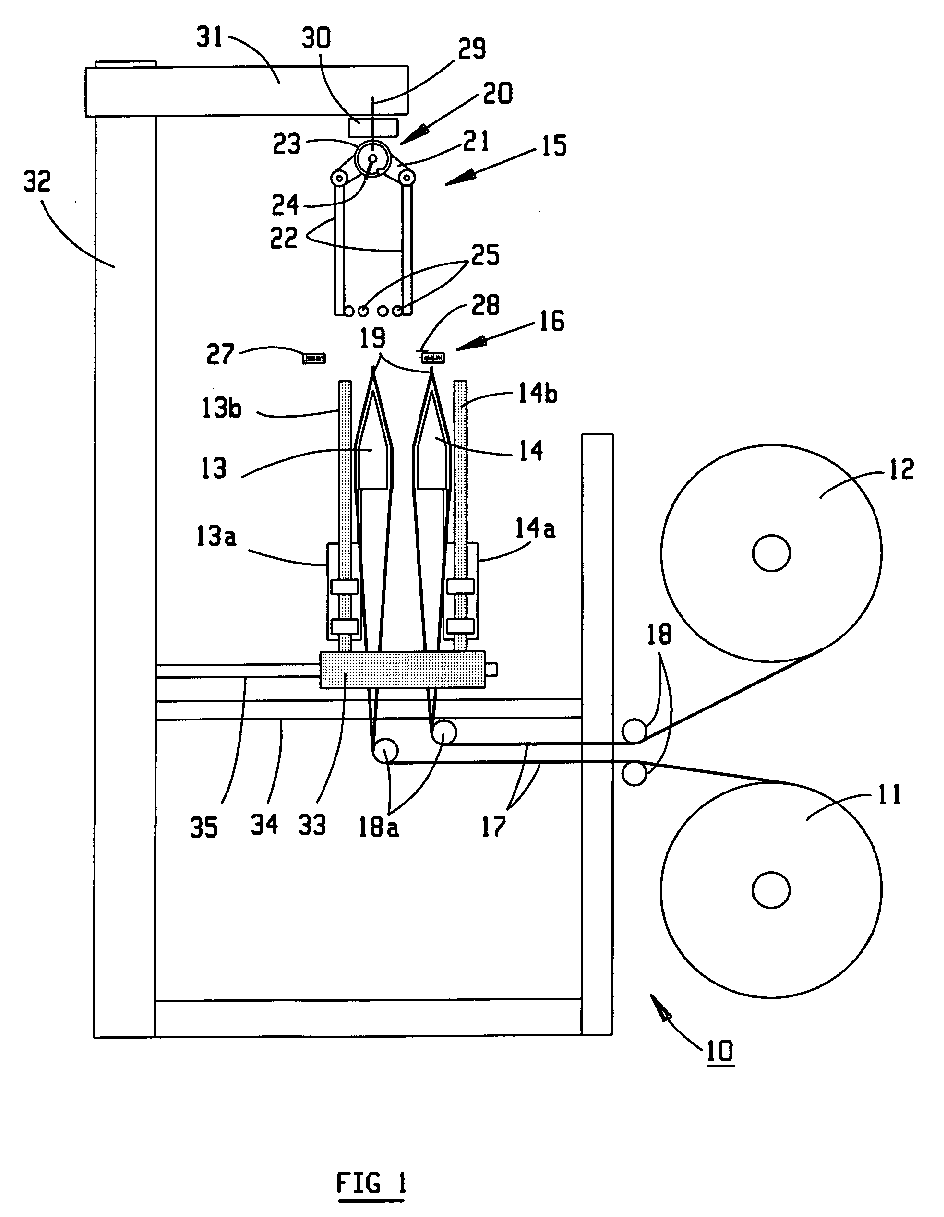
- a preparation station 10 of a cover of packaging comprises a pair of coils 11, 12 for storing a sheath 17 plastic, a pair of positioners 13, 14 for opening and positioning sheath 17 from each coil 11, 12, a transfer device and 15, and welding and cutting means 16 to constitute from each coil 11, 12, a cover HO of a predetermined length and wound on the transfer and accumulation device 15.
- the packaging sheath 17 is formed by a plastic film with double V gussets, and folded flat after winding around each cylindrical coil 11, 12. This type of sheath is described in detail in EP-A-1060988. She is then unrolled, passes over guide rollers 18, 18a, and is maintained in vertical position with the bellows solicited by the organs positioners 13, 14. Previously, the middle portion of each sheath 17 has been welded transversely to its free end to obtain a watertight bottom through forming a heat-sealed bond 19.
- the casing 17 with bellows can also be replaced by a simple tubular sheath without gussets, and also folded flat on the coils 11, 12.
- the film of the sheath 17 may be of heat-shrinkable plastic or stretchable plastic.
- Figures 3 to 9 show an application with a heat-shrinkable film, while Figures 10-18 illustrate another application with stretch film.
- the steps of the process of forming the HO cover at the post of preparation 10 are identical irrespective of the heat-shrinkable nature or stretch of film used.
- the transfer and accumulation device 15 comprises an accumulator element 20 and a spacing mechanism 21 with four swinging arms 22.
- the element accumulator 20 is provided by way of example of a motorized rotary roller 23 on which is wound a portion of the sheath 17, which is held by a clamp retainer 24 integrated in the roller 23.
- the four rocker arms 22 of the spacing mechanism 21 are equipped with gripping tongs 25, arranged at each end to guide and grip the sheath 17.
- the welding and cutting means 16 comprise a two-jaw welder 27 mobiles able to move in a horizontal plane symmetrically relative to the positioners 13, 14.
- the upper part of the welder comprises a linear cutting device 28 equipped with a straight cutting blade actuated by a jack.
- the transfer and accumulation device 15 is pivotally mounted around a vertical axis 29 for positioning the heat-sealed connection 19 of the HO cover parallel or perpendicular to the largest face of the load CH, which generally has a parallelepiped shape. Moving from the cover HO between the preparation station 10, and the stuffing station 26 exclusively in a horizontal plane by means of a trolley of transfer 30 carried by an actuating arm 31, which is arranged at the top a 32 vertical frame.
- the positioners 13, 14 are movable in the direction of the height, to move the heat-sealed connection 19 of the cover from a position (Fig. 1) to a high position (Fig. 2) for insertion into the retainer 24 of the accumulator roll 23.
- the high position corresponds to an altitude substantially equal to or greater than the level of the upper face of the load C H located on the side of the berth 26.
- the actuators 13a, 14a of the positioners 13, 14 are guided in translation by rods 13b, 14b vertical solidarity of a support 33, which is located on a horizontal bridge 34 fixed to the frame 22.
- the support 33 can slide along a horizontal crossbar arranged slightly above the gateway 34 so as to position one of the members alternately positioners 13, 14 opposite the retaining clip 24.
- the welding and cutting means 16 are intercalated at an intermediate level between the gripping tongs 25 of the rocking arms 22 and the ends upper rods 13b, 14b guide.
- the palletised CH load is carried in the filling station 26 by a table 36 chains or rollers.
- a removal arm 37 of the HO cover can slide vertically along the frame 32, and is provided with fingers 38 of conformation and pinching for the recovery of the open part of the HO cover at the four corners when laying on the load CH ( Figures 3 to 9). These fingers 38 are arranged to receive a HO cover of heat-shrinkable plastic film.
- the charge CH coated with its HO cover is then moved to a downstream station, which is equipped with a hot air heating frame for heat shrinking of the HO cover on the charge CH.
- the two positioner members 13, 14 are waiting in position low, ensuring the horizontal maintenance of the heat-sealed connection 19 of the two sheaths 17 from the two coils 11, 12.
- the welding jaws 27 above rods 13b, 14b are spaced from each other, and the retaining clip 24 of the accumulator roll 23 is opened to release the gripping area of the link heat-sealed 19 of the sheath 17 selected.
- the support 33 is moved to the right so as to place the positioner member 13 opposite the gripper 24.
- the swing arms 22 are in the retracted position, and the arm actuator 31 is on the right above the preparation station 10 of the cover packaging. In this production standby position, the internal volume of two sheaths 17 is protected by the associated heat-sealed connection 19, avoiding any penetration of ambient dust.
- the positioner member 13 associated with the first coil 11 is moved to the high position above the upper level of the load at wrap. In its displacement in translation upwards, the positioner member 13 causes the unwinding of the coil 11, and entails the heat-sealed connection 19 in the retaining clip 24.
- the gripping tongs 25 of the four arms 22 are spaced apart, as well as the welding jaws 27.
- the other positioner member 14 remains stationary in the low position, without unwinding the coil 12.
- a new load CH is brought to the table 36 to be wrapped by the cover in preparation on the roll 23 of the post 10.
- the arm deposit 37 has been raised in translation above the charge CH to be packaged, with transverse refocusing of the recovery fingers 38.
- the welding jaws 27 are move against each other to make a new heat-sealed connection 19 which will be used to make a new cover.
- the cutting device 28 has been actuated to cut the HO cover to the desired length, while the jaws 27 remain in close position.
- the actuating arm 31 is moved horizontally to the left over the 26, and the translation of the transfer carriage 30 ensures the exact positioning of the roller 23 above the deposition arm 37.
- the four swinging arms 22 are actuated to the spread position to cause the opening of the lower free end of the HO cover. This end of the HO cover is then taken by the fingers 38 of the deposition arm 37, which are spread apart to be under the clamps 25 of the arms 22. In this step, the roller 23 is motorized in the direction of unwinding.
- the retaining clip 24 of the roll 23 is opened to release the heat-sealed connection 19 of the HO cover.
- the removal arm 37 begins its downward movement to gradually wrap the CH load with the HO cover, while the arms 22 remain in the separated position while maintaining the cover spread by its four angles.
- the welding jaws 27 and the device for section 28 return to the rest position.
- the cover HO has left the gripping tongs 25 of the arms 22, and the removal arm 37 arrives towards the bottom of the load CH in the station of 26.
- the actuating arm 31 and the carriage 30 turn back to the right. above the preparation station 10, and the arms 22 are actuated towards the retracted position.
- the support 33 is moved in translation to the left along of the cross member 35, so as to select the positioner member 14 associated with the second coil 12. The positioner member 14 can thus be actuated upwards without waiting for the final return of the transfer and accumulation device 15.
- the removal arm 37 is being raised, and the device 15 ensures the winding and storage of a predetermined length of sheath 17 around the rotary roller 23.
- the positioner member 14 descends during this winding phase of the sheath.
- FIGS. 10 to 18 The following sequence of operation illustrated in FIGS. 10 to 18 is carried out with a stretch film sheath.
- the organs of the preparation 10 of the cover HO are identical to those of FIGS. 1 to 9.
- structure of the deposition arm 37 in the filling station is different, and instead of the conformation and pinching fingers 38, fingers of pleating and stretching 39 associated with motorized rollers 40.
- the installation of a stretchable sheath does not require a source heat shrink, because it is sufficient to stretch mechanically at beforehand the material of the plastic film in the horizontal transverse direction before to wrap the palletized load to be wrapped.
- Each finger 39 is mounted on a control member 41 driven by an actuator of the type cylinder or geared motor in a direction substantially confused with the diagonal of the load CH.
- FIG. 10 corresponding to the following sequence of FIG. positioner 14 continues its descent movement towards the low position, and a new load CH to be packed is brought on the table 36 of the station of hooding.
- the removal arm 37 is raised in translation above the CH load, with transverse refocusing of the pleating fingers 39.
- the rollers 40 are spaced from the fingers 39, and the sheath 17 from the coil 12 is wound around the accumulator roller.
- the actuating arm 31 is moved horizontally to the left above the stuffing station 26.
- the transfer trolley 30 is also moves in the same direction to ensure the exact positioning of the roller 23 above the drop arm 37.
- the four rocker arms 22 are actuated to the spread position to cause the opening of the free end bottom of the HO cover.
- the fingers 39 of the deposition arm 37 are discarded to be placed under the forceps 25 of the rocking arms 22.
- Figures 14 and 15 show the pleating and accumulation phase of the cover HO on the lower part of the fingers 39. Accordion pleating of the HO cover intervenes following the rotation of the motorized rollers 40 which are in contact with the four fingers 39.
- FIG. 16 shows the transverse stretching of the folded HO cover following the maximum spacing of the control members 41 of the fingers 39.
- the rollers 40 do not touch during this phase of transverse stretching of the HO cover, which is stretched with an elongation rate greater than 30%.
- the time saved is the duration of the uphill race of a positioner member 13 or 14 between the low position and the intermediate position Wait.
- FIG. 23 represents a variant of the accumulator element 20 of the device 15, wherein the rotary roller 23 is replaced by a moving roller system.
- the packing rate of the machine can still be increased by making use of two accumulator systems to altered movements.
Landscapes
- Engineering & Computer Science (AREA)
- Mechanical Engineering (AREA)
- Basic Packing Technique (AREA)
Abstract
Un dispositif de mise en forme et de dépose d'une housse (HO) d'emballage sur
une charge (CH) palettisée comporte au moins un organe positionneur (13, 14)
agencé entre une bobine (11, 12) de stockage de la gaine 17, et un élément
accumulateur (20) pour le maintien de la gaine (17). L'organe positionneur (13, 14)
est mobile en hauteur dans le poste de préparation (10) en étant accouplé à un
actionneur (13a, 14a) de manière à déplacer la gaine (17) entre une position
d'attente, et une position haute d'engagement de la liaison thermosoudée (19)
dans l'élément accumulateur (20).
Description
L'invention est relative à un procédé et un dispositif de mise en forme et de dépose d'une housse d'emballage sur une charge palettisée, ladite housse étant préparée à partir d'une gaine en matière plastique souple enroulée sur au moins une bobine de stockage, procédé consistant à :
- souder transversalement la gaine à son extrémité libre pour créer une liaison thermosoudée maintenue dans une position basse par au moins un organe positionneur,
- stocker sur un dispositif de transfert et d'accumulation une longueur prédéterminée de gaine pour constituer ladite housse,
- reprendre l'extrémité libre inférieure, et descendre la housse autour de la charge à emballer, en la maintenant écartée par ses quatre angles.
- transversely welding the sheath at its free end to create a heat-welded connection held in a low position by at least one positioner member,
- storing on a transfer and accumulation device a predetermined length of sheath to constitute said cover,
- take the lower free end, and lower the cover around the load to be wrapped, keeping it separated by its four angles.
Le document EP-A-1060988 décrit un dispositif de suremballage d'une charge palettisée au moyen d'une housse préparée à partir d'une gaine à soufflets enroulée à plat sur une bobine de stockage. Un robot de préhension comporte un rouleau accumulateur motorisé sur lequel est enroulée une partie de la gaine, un bras de transfert du rouleau vers le poste de houssage, et un mécanisme d'écartement de la housse pendant le mouvement de descente autour de la charge. La gaine préalablement soudée dans le sens transversal, est maintenue en position verticale avec les soufflets sollicités en ouverture par un organe positionneur, lequel est fixe et disposé avec la bobine au voisinage du sol. Le bras de transfert du robot est porté par un coulisseau mobile en translation verticale sur le bâti. Le bras du robot est ainsi animé d'un premier mouvement horizontal de translation lors du transfert, et d'un deuxième mouvement de descente pour préparer la housse par soudage et coupe après son enroulement autour du rouleau accumulateur. Ce deuxième déplacement vertical du bras est indispensable, étant donné que l'organe positionneur de la gaine est fixe. Ce mouvement combiné du robot rallonge le temps de préparation et de dépose de la housse, et limite les cadences d'emballage de la machine.EP-A-1060988 discloses a device for overpacking a load palletized by means of a cover prepared from a bellows sleeve rolled flat on a reel of storage. A gripper robot has a motorized accumulator roller on which is wound a part of the sheath, a roller transfer arm to the stuffing station, and a mechanism spreading the cover during the downward movement around the charge. The sheath previously welded in the transverse direction, is maintained in vertical position with bellows solicited by an organ positioner, which is fixed and arranged with the coil in the vicinity of the ground. The robot transfer arm is carried by a mobile slide in vertical translation on the frame. The robot's arm is thus animated by a first horizontal movement of translation during the transfer, and a second downward movement for prepare the cover by welding and cutting after wrapping around the roll accumulator. This second vertical movement of the arm is indispensable, being given that the positioner member of the sheath is fixed. This combined movement of robot lengthens the time of preparation and removal of the cover, and limits packaging rates of the machine.
Le document EP-A-395919 se rapporte à une machine d'emballage d'une charge palettisée au moyen d'un film thermorétractable, comprenant quatre barres verticales équipées de pinces de préhension du film pouvant monter et descendre dans le bâti, un four de rétraction annulaire, une paire de traverses horizontales et deux chariots pouvant se déplacer horizontalement le long des traverses. Les barres se rapprochent lorsque le chariot se déplace vers la section de distribution, et s'écartent lorsque le chariot se déplace au-dessus de la charge à emballer. Ce mécanisme assure également le houssage. La cinématique d'une telle machine ne permet pas de réduire les cadences d'emballage, et est limitée à des charges de hauteurs peu élevées.EP-A-395919 relates to a machine for packing a load palletized with heat-shrinkable film, comprising four bars verticals equipped with grippers film up and down in the frame, an annular retraction furnace, a pair of horizontal struts and two trolleys that can move horizontally along the sleepers. The bars come closer when the carriage moves to the dispensing section, and move apart when the carriage moves over the load to be packaged. This mechanism also ensures the hulling. The kinematics of such a machine does not does not reduce packaging rates, and is limited to low heights.
Le document EP 1106507 mentionne une machine d'emballage, dans laquelle la liaison thermosoudée au lieu d'être disposée en haut, est orientée vers le bas. Il est alors nécessaire de housser à l'envers. L'organe positionneur et la soudeuse restent situés dans la partie basse. Un tel dispositif est adapté pour des charges de faibles hauteurs, mais pas pour des hauteurs élevées.EP 1106507 mentions a packaging machine, in which the heat-sealed connection instead of being arranged at the top, is oriented downwards. he it is then necessary to turn upside down. The positioner and the welder remain in the lower part. Such a device is suitable for loads low heights, but not for high heights.
Un premier objet de l'invention consiste à améliorer le procédé de préparation et de dépose d'une housse sur une charge palettisée, pour accélérer les cycles d'emballage et augmenter les cadences de production.A first object of the invention is to improve the preparation process and removal of a cover on a palletized load, to accelerate the cycles packaging and increase production rates.
Le procédé d'emballage selon l'invention est caractérisé par les étapes intermédiaires suivantes :
- déplacer l'organe positionneur verticalement vers le haut en entraínant la gaine jusqu'à une position haute d'engagement de la liaison thermosoudée dans le dispositif de transfert et d'accumulation
- et déplacer horizontalement le dispositif de transfert et d'accumulation selon un seul mouvement horizontal dirigé orthogonalement par rapport au déplacement de l'organe positionneur pour assurer la reprise de l'extrémité inférieure de la housse.
- moving the positioner member vertically upwardly by driving the sleeve to a high position for engagement of the heat-sealed connection in the transfer and accumulation device
- and horizontally moving the transfer and accumulation device in a single horizontal movement directed orthogonal to the movement of the positioner member to ensure the recovery of the lower end of the cover.
Durant la course de retour du dispositif de transfert et d'accumulation, l'organe positionneur est déplacé vers une position intermédiaire d'attente située juste avant ladite position haute de prise du film dans l'élément accumulateur. Il en résulte un gain de temps correspondant à la durée de la course de montée d'un organe positionneur entre la position basse et la position intermédiaire d'attente.During the return stroke of the transfer and accumulation device, the organ positioner is moved to an intermediate waiting position just before said upper position of the film in the accumulator element. This results in a time saving corresponding to the duration of the rise stroke of an organ positioner between the low position and the intermediate waiting position.
Pour confectionner la housse, on peut utiliser une gaine tubulaire avec ou sans soufflets, et réalisée en matière plastique thermorétractable ou étirable.To make the cover, you can use a tubular sheath with or without bellows, and made of heat-shrinkable or stretchable plastic.
Le déplacement vertical de la gaine vers le haut par entraínement de l'organe positionneur, et le transfert horizontal de la housse enroulée sur l'organe accumulateur, occasionnent deux mouvements de translation indépendants l'un de l'autre, contrairement au mouvement combiné du robot selon le document EP-A-1060988. Il en résulte une accélération des cycles d'emballage, et une augmentation des cadences de production.The vertical displacement of the sheath upwards by driving the organ positioner, and the horizontal transfer of the cover wound on the body accumulator, cause two independent translation movements, one of the other, unlike the combined movement of the robot according to EP-A-1060988. This results in an acceleration of the packaging cycles, and a increased production rates.
Un deuxième objet de l'invention consiste à réaliser une machine pour la mise en forme et la dépose d'une housse d'emballage sur une charge palettisée, autorisant des cadences de production élevées, et pouvant utiliser indifféremment une gaine plastique thermorétractable ou étirable.A second object of the invention is to provide a machine for the implementation of form and removal of a packaging cover on a palletized load, allowing high production rates, and can use indifferently a sheath heat-shrinkable or stretchable plastic.
La machine comporte un dispositif de transfert et d'accumulation comprenant un élément accumulateur sur lequel est enroulée une partie de la gaine, et un mécanisme d'écartement de l'extrémité ouverte de la gaine après transfert vers le poste de houssage. Selon l'invention, l'organe positionneur est mobile en hauteur dans le poste de préparation en étant accouplé à un actionneur, de manière à déplacer la gaine entre une position basse d'attente, et une position haute d'engagement de la liaison thermosoudée dans l'élément accumulateur.The machine comprises a transfer and accumulation device comprising a accumulator element on which is wound a portion of the sheath, and a mechanism of separation of the open end of the sheath after transfer to the padding station. According to the invention, the positioner member is movable in height in the preparation station by being coupled to an actuator, so as to move the sheath between a low standby position and a high position engaging the heat-sealed connection in the accumulator element.
Le dispositif de transfert et d'accumulation est monté à pivotement sur un axe vertical d'un bras d'actionnement pour positionner la liaison thermosoudée parallèlement ou perpendiculairement à la plus grande face de la charge. L'organe positionneur est guidé en translation verticale entre les deux positions basse et haute par une tige de guidage ou glissière solidaire d'un support.The transfer and accumulation device is pivotally mounted on an axis vertical of an actuating arm to position the heat-sealed connection parallel or perpendicular to the largest face of the load. The organ positioner is guided in vertical translation between the two low and high by a guide rod or slide secured to a support.
D'autres caractéristiques peuvent être utilisées en combinaison :
- le support des deux organes positionneurs est monté sur une passerelle fixée au bâti au-dessus du sol;
- le support est ajustable sur une traverse horizontale solidaire du bâti, et est doté de deux organes positionneurs susceptibles d'être mis altemativement en regard de l'organe accumulateur par un mouvement horizontal de translation du support ;
- les organes positionneurs maintiennent des gaines issues de deux bobines superposées, dont l'axe s'étend parallèlement ou perpendiculairement au transporteur de manutention ;
- le bras de dépose est pourvu de doigts de conformation et de pincement pour la reprise aux quatre angles de la partie ouverte d'une housse de film plastique thermorétractable ;
- le bras de dépose est pourvu de doigts de plissage et d'étirage destinés à assurer successivement le plissage en accordéon de la housse de film plastique étirable suite à la rotation de galets motorisés, suivi d'un étirage transversal aux quatre angles avant la descente autour de la charge.
- the support of the two positioners is mounted on a bridge fixed to the frame above the ground;
- the support is adjustable on a horizontal crosspiece integral with the frame, and is provided with two positioners members may be placed alternately facing the accumulator member by a horizontal translational movement of the support;
- the positioners maintain sheaths from two superimposed coils, whose axis extends parallel or perpendicular to the handling conveyor;
- the removal arm is provided with shaping fingers and pinching for the recovery at the four corners of the open portion of a heat-shrinkable plastic film cover;
- the removal arm is provided with pleating and drawing fingers intended to ensure successively the accordion pleating of the stretch plastic film cover following the rotation of motorized rollers, followed by a transverse stretching at the four angles before the descent around of the charge.
D'autres avantages et caractéristiques ressortiront plus clairement de la description qui va suivre d'un mode de réalisation de l'invention donné à titre d'exemple non limitatif, et représenté aux dessins annexés, dans lesquels:
- les figures 1 et 2 sont des vues schématiques du poste de préparation de la housse selon l'invention, avec deux organes positionneurs respectivement en position d'attente, et en position de déplacement de l'un des organes positionneurs vers l'élément accumulateur ;
- les figures 3 à 9 montrent des vues schématiques du dispostif complet avec le poste de préparation et le poste de houssage faisant usage d'un cadre de dépose d'une gaine thermorétractable, le dispositif étant illustré dans différentes phases de préparation, de transfert et de dépose de la housse ;
- les figures 10 à 18 représentent les phases suivantes du fonctionnement du dispositif avec un cadre de dépose adapté à une gaine étirable ;
- la figure 19 est une vue de profil du poste de préparation de la housse ;
- les figures 20 à 22 montrent les étapes successives de retour du rouleau accumulateur et des bras balanciers pour la prise du film à cadence élevée ;
- la figure 23 est une vue identique du poste de préparation de la figure 1, avec une variante de l'organe accumulateur.
- Figures 1 and 2 are schematic views of the preparation station of the cover according to the invention, with two positioners respectively in standby position, and in the displacement position of one of the positioners to the accumulator element;
- FIGS. 3 to 9 show schematic views of the dispositive complete with the preparation station and the filling station making use of a heat-shrinkable sheath removal frame, the device being illustrated in different stages of preparation, transfer and removing the cover;
- Figures 10 to 18 show the following phases of operation of the device with a dispensing frame adapted to a stretchable sheath;
- Figure 19 is a side view of the preparation station of the cover;
- Figures 20 to 22 show the successive steps of returning the accumulator roller and the rocker arms for taking the film at high rate;
- Figure 23 is an identical view of the preparation station of Figure 1, with a variant of the accumulator member.
En référence aux figures 1 à 2, un poste de préparation 10 d'une housse
d'emballage, comporte une paire de bobines 11, 12 de stockage d'une gaine 17
plastique, une paire d'organes positionneurs 13, 14 destinés à ouvrir et positionner
la gaine 17 en provenance de chaque bobine 11, 12, un dispositif de transfert et
d'accumulation 15, et des moyens de soudage et de coupe 16 pour constituer à
partir de chaque bobine 11, 12, une housse HO d'une longueur prédéterminée et
enroulée sur le dispositif de transfert et d'accumulation 15.With reference to FIGS. 1 to 2, a
La gaine 17 d'emballage est formée par un film plastique à soufflets en double V,
et pliée à plat après enroulement autour de chaque bobine 11, 12 cylindrique. Ce
type de gaine est décrit en détail dans le document EP-A-1060988. Elle est
ensuite déroulée, passe sur des galets de guidage 18, 18a, et est maintenue en
position verticale avec les soufflets sollicités en ouverture par les organes
positionneurs 13, 14. Préalablement, la partie médiane de chaque gaine 17 a été
soudée transversalement à son extrémité libre pour obtenir un fond étanche grâce
à la formation d'une liaison thermosoudée 19. The
La gaine 17 à soufflets peut aussi être remplacée par une simple gaine tubulaire
sans soufflets, et également pliée à plat sur les bobines 11, 12.The
Le film de la gaine 17 peut être en matière plastique thermorétractable ou étirable.
Les figures 3 à 9 montrent une application avec un film thermorétractable, tandis
que les figures 10 à 18 illustrent une autre application avec un film étirable. Les
étapes du procédé de formation de la housse HO au niveau du poste de
préparation 10 sont identiques, indépendamment de la nature thermorétractable ou
étirable du film utilisé.The film of the
Le dispositif de transfert et d'accumulation 15 comporte un élément accumulateur 20
et un mécanisme d'écartement 21 à quatre bras balanciers 22. L'élément
accumulateur 20 est pourvu à titre d'exemple d'un rouleau rotatif 23 motorisé sur
lequel est enroulée une partie de la gaine 17, laquelle est maintenue par une pince
de retenue 24 intégrée dans le rouleau 23. Les quatre bras balanciers 22 du
mécanisme d'écartement 21 sont équipés de pinces de préhension 25, agencées
à chaque extrémité pour guider et saisir la gaine 17.The transfer and
Dans la position de repos (figure 1) et pendant la phase d'enroulement d'une gaine
17 autour du rouleau 23 (figures 2 à 4), les quatre bras balanciers 22 se trouvent en
position rétractée. L'actionnement des bras balanciers 22 vers la position écartée
(figures 5 et 6) est effectué par pivotement au moyen de vérins pneumatiques
intervenant lors du transfert vers le poste de houssage 26.In the rest position (Figure 1) and during the winding phase of a
Les moyens de soudage et de coupe 16 comportent une soudeuse à deux mors
27 mobiles susceptibles de se déplacer dans un plan horizontal symétriquement
par rapport aux organes positionneurs 13, 14. La partie supérieure de la soudeuse
comprend un dispositif de coupe 28 linéaire équipé d'une lame de coupe rectiligne
actionnée par un vérin.The welding and cutting means 16 comprise a two-
Le dispositif de transfert et d'accumulation 15 est monté à pivotement autour d'un
axe 29 vertical pour positionner la liaison thermosoudée 19 de la housse HO
parallèlement ou perpendiculairement à la plus grande face de la charge CH,
laquelle présente généralement une forme parallélépipédique. Le déplacement de
la housse HO entre le poste de préparation 10, et le poste de houssage 26
s'opère exclusivement dans un plan horizontal par l'intermédiaire d'un chariot de
transfert 30 porté par un bras d'actionnement 31, lequel est agencé au sommet
d'un bâti 32 vertical.The transfer and
Les organes positionneurs 13, 14 sont mobiles dans le sens de la hauteur, de
manière à déplacer la liaison thermosoudée 19 de la housse à partir d'une position
basse (figure 1) vers une position haute (figure 2) pour l'introduire dans la pince de
retenue 24 du rouleau 23 accumulateur. La position haute correspond à une altitude
sensiblement égale ou supérieure au niveau de la face supérieure de la charge C H
se trouvant du côté du poste de houssage 26.The
Les actionneurs 13a, 14a des organes positionneurs 13, 14 sont guidés en
translation par des tiges 13b, 14b verticales solidaires d'un support 33, lequel se
trouve sur une passerelle 34 horizontale fixée au bâti 22. Le support 33 peut
coulisser le long d'une traverse 35 horizontale agencée légèrement au-dessus de la
passerelle 34, de manière à positionner altemativement l'un des organes
positionneurs 13, 14 en regard de la pince de retenue 24.The
Les moyens de soudage et de coupe 16 sont intercalés à un niveau intermédiaire
entre les pinces de préhension 25 des bras balanciers 22 et les extrémités
supérieures des tiges 13b, 14b de guidage.The welding and cutting means 16 are intercalated at an intermediate level
between the
La charge CH palettisée est portée dans le poste de houssage 26 par une table
36 à chaínes ou à rouleaux. Un bras de dépose 37 de la housse HO peut
coulisser verticalement le long du bâti 32, et est pourvu de doigts 38 de
conformation et de pincement pour la reprise de la partie ouverte de la housse HO
aux quatre angles lors de la dépose sur la charge CH (figures 3 à 9). Ces doigts
38 sont agencés pour recevoir une housse HO de film plastique thermorétractable.
La charge CH revêtue de sa housse HO est ensuite déplacée vers un poste aval,
lequel est équipé d'un cadre chauffant à air chaud assurant la thermorétraction de la
housse HO sur la charge CH. The palletised CH load is carried in the filling
Le fonctionnement du dispositif de suremballage avec une gaine 17
thermorétractable, est illustré sur les figures 1 à 9:The operation of the overpack device with a
Sur la figure 1, les deux organes positionneurs 13, 14 sont en attente en position
basse, en assurant le maintien horizontal de la liaison thermosoudée 19 des deux
gaines 17 en provenance des deux bobines 11, 12. Les mors 27 de soudage au-dessus
des tiges 13b, 14b sont écartés l'un de l'autre, et la pince de retenue 24 du
rouleau 23 accumulateur est ouverte pour libérer la zone d'agrippage de la liaison
thermosoudée 19 de la gaine 17 sélectionnée. Le support 33 est déplacé vers la
droite de manière à placer l'organe positionneur 13 en regard de la pince de
retenue 24. Les bras balanciers 22 se trouvent en position rétractée, et le bras
d'actionnement 31 est à droite au-dessus du poste de préparation 10 de la housse
d'emballage. Dans cette position d'attente de production, le volume inteme des
deux gaines 17 est protégé par la liaison thermosoudée 19 associée, en évitant
toute pénétration de poussière ambiante.In FIG. 1, the two
Sur la figure 2, l'organe positionneur 13 associé à la première bobine 11, est
déplacé vers la position haute située au-dessus du niveau supérieur de la charge à
emballer. Dans son déplacement en translation vers le haut, l'organe positionneur
13 provoque le déroulement de la bobine 11, et entraíne la liaison thermosoudée
19 dans la pince de retenue 24. Les pinces de préhension 25 des quatre bras 22
sont écartées, ainsi que les mors 27 de soudage. L'autre organe positionneur 14
reste immobile en position basse, sans dérouler la bobine 12.In FIG. 2, the
Dans l'étape de la figure 3 intervient l'enroulement et le stockage d'une longueur
prédéterminée de gaine 17 autour du rouleau 23 motorisé qui tourne dans le sens
des aiguilles d'une montre. L'organe positionneur 13 redescend en direction de la
position basse, et les pinces de préhension 25 des quatre bras 22 s'engagent
entre les soufflets de la gaine 17. Sur le poste de houssage 26, une charge CH
précédente est totalement enveloppée par une housse HO, laquelle a été
préalablement préparée et transférée par le dispositif de transfert et d'accumulation
15. Cette charge CH emballée est ensuite évacuée sur la table 36 vers un poste
aval où est opérée l'opération de thermorétraction. Il est également possible de
prévoir un cadre de rétraction à air chaud autour de la charge pour effectuer la
thermorétraction dans le poste de houssage, comme décrit dans le document EP-A-1060988.In the step of Figure 3 is involved the winding and storage of a length
predetermined
Sur la figure 4, une nouvelle charge CH est amenée sur la table 36 pour être
enveloppée par la housse en préparation sur le rouleau 23 du poste 10. Le bras
de dépose 37 a été relevé en translation au-dessus de la charge CH à emballer,
avec recentrage transversal des doigts 38 de reprise. Les mors 27 de soudage se
rapprochent l'un contre l'autre pour effectuer une nouvelle liaison thermosoudée 19
qui servira pour confectionner une nouvelle housse.In FIG. 4, a new load CH is brought to the table 36 to be
wrapped by the cover in preparation on the
Sur la figure 5, le dispositif de coupe 28 a été actionné pour couper la housse HO à
la longueur souhaitée, alors que les mors 27 restent en position rapprochée. Le
bras d'actionnement 31 est déplacé horizontalement vers la gauche au-dessus du
poste de houssage 26, et la translation du chariot 30 de transfert assure le
positionnement exact du rouleau 23 au-dessus du bras de dépose 37. Les quatre
bras balanciers 22 sont actionnés vers la position écartée pour provoquer
l'ouverture de l'extrémité libre inférieure de la housse HO. Cette extrémité de la
housse HO est ensuite reprise par les doigts 38 du bras de dépose 37, lesquels
sont écartés pour se placer sous les pinces 25 des bras 22. Dans cette étape, le
rouleau 23 est motorisé dans le sens du déroulement.In FIG. 5, the cutting
Sur la figure 6, la pince de retenue 24 du rouleau 23 est ouverte pour libérer la
liaison thermosoudée 19 de la housse HO. Le bras de dépose 37 commence son
mouvement de descente pour envelopper progressivement la charge CH avec la
housse HO, alors que les bras 22 restent en position écartée en maintenant la
housse écartée par ses quatre angles. Les mors 27 de soudage et le dispositif de
coupe 28 reviennent en position de repos.In FIG. 6, the retaining
Sur la figure 7, la housse HO a quitté les pinces de préhension 25 des bras 22, et
le bras de dépose 37 arrive vers le bas de la charge CH dans le poste de
houssage 26. Le bras d'actionnement 31 et le chariot 30 retoument vers la droite
au-dessus du poste de préparation 10, et les bras 22 sont actionnés vers la
position rétractée. Le support 33 est déplacé en translation vers la gauche le long
de la traverse 35, de manière à sélectionner l'organe positionneur 14 associé à la
deuxième bobine 12. L'organe positionneur 14 peut ainsi être actionné vers le haut
sans attendre le retour final du dispositif de transfert et d'accumulation 15.In FIG. 7, the cover HO has left the gripping
Sur la figure 8, la charge CH est totalement emballée par la housse HO, et l'organe
positionneur 14 se trouve en position haute en provoquant l'insertion de la liaison
thermosoudée 19 dans la pince de retenue 24 du rouleau 23 accumulateur. L'autre
organe positionneur 13 est en attente en position basse.In FIG. 8, the load CH is totally packed by the cover HO, and the
Sur la figure 9, le bras de dépose 37 est en cours de relevage, et le dispositif 15
assure l'enroulement et le stockage d'une longueur prédéterminée de gaine 17
autour du rouleau 23 rotatif. L'organe positionneur 14 redescend pendant cette
phase d'enroulement de la gaine.In FIG. 9, the
La suite de la séquence de fonctionnement illustrée sur les figures 10 à 18
s'effectue avec une gaine à film étirable. Dans ce cas, les organes du poste de
préparation 10 de la housse HO sont identiques à ceux des figures 1 à 9. La
structure du bras de dépose 37 dans le poste de houssage est différent, et
comporte à la place des doigts de conformation et de pincement 38, des doigts de
plissage et d'étirage 39 associés à des galets 40 motorisés. Contrairement au film
thermorétractable, la mise en place d'une gaine étirable ne nécessite pas de source
de chaleur pour assurer la thermorétraction, car il suffit d'étirer mécaniquement au
préalable la matière du film plastique dans le sens transversal horizontal avant
d'envelopper la charge palettisée à emballer. Après la dépose de la housse étirée
sur la charge, le resserrement de la matière du film étirable s'effectue naturellement
par élasticité, ce qui maintient fermement la housse autour de la charge. Chaque
doigt 39 est monté sur un organe de commande 41 entraíné par un actionneur du
type vérin ou motoréducteur selon une direction confondue sensiblement avec la
diagonale de la charge CH.The following sequence of operation illustrated in FIGS. 10 to 18
is carried out with a stretch film sheath. In this case, the organs of the
Sur la figure 10 correspondant à la séquence suivante de la figure 9, l'organe
positionneur 14 poursuit son mouvement de descente vers la position basse, et
une nouvelle charge CH à emballer est amenée sur la table 36 du poste de
houssage. Le bras de dépose 37 se trouve relevé en translation au-dessus de la
charge CH, avec recentrage transversal des doigts de plissage 39. Les galets 40
sont écartés des doigts 39, et la gaine 17 issue de la bobine 12 est enroulée
autour du rouleau 23 accumulateur.In FIG. 10 corresponding to the following sequence of FIG.
Sur la figure 11, les mors 27 de soudage se rapprochent l'un contre l'autre pour
effectuer une nouvelle liaison thermosoudée 19, et l'ensemble rouleau 23 et bras
balanciers 22 reste immobilisé au-dessus des mors 27 jusqu'à l'intervention du
dispositif de coupe 28.In FIG. 11, the
Sur les figures 12 et 13, le bras d'actionnement 31 est déplacé horizontalement
vers la gauche au-dessus du poste de houssage 26. Le chariot 30 de transfert se
déplace également dans le même sens pour assurer le positionnement exact du
rouleau 23 au-dessus du bras de dépose 37. Les quatre bras balanciers 22 sont
actionnés vers la position écartée pour provoquer l'ouverture de l'extrémité libre
inférieure de la housse HO. Les doigts 39 du bras de dépose 37 sont écartés
pour se placer sous les pinces 25 des bras balanciers 22.In FIGS. 12 and 13, the
Les figures 14 et 15 montrent la phase de plissage et d'accumulation de la housse
HO sur la partie basse des doigts 39. Le plissage en accordéon de la housse HO
intervient suite à la rotation des galets 40 motorisés qui sont en contact avec les
quatre doigts 39.Figures 14 and 15 show the pleating and accumulation phase of the cover
HO on the lower part of the
Sur la figure 16 intervient l'étirage transversal de la housse HO plissée suite à
l'écartement maximum des organes de commande 41 des doigts 39. Les galets
40 ne toument pas pendant cette phase d'étirage transversal de la housse HO,
laquelle est tendue avec un taux d'allongement supérieur à 30%.FIG. 16 shows the transverse stretching of the folded HO cover following
the maximum spacing of the
Sur les figures 17 à 22, le mouvement de descente du bras de dépose 37
provoque le déplissage progressif de la housse HO autour de la charge CH. Le
bras d'actionnement 31 et le chariot 30 retoument vers le poste de préparation 10,
et les bras 22 sont actionnés vers la position rétractée. Au début de la course de
retour (figure 17), les deux organes positionneurs 13, 14 se trouvent tous les deux
en position basse. La course poursuivie de retour de l'élément accumulateur 20
s'effectue par un mouvement de coulissement transversal (figure 18), et les bras
balanciers 22 passent de part et d'autre des organes positionneurs 13, 14 (figure
19). L'organe positionneur 14 peut ainsi être déplacé vers le haut vers une position
d'attente (figure 20), située juste avant la position haute de fin de course. Lorsque le
rouleau accumulateur 23 et la pince de retenue 24 arrivent en regard du film
maintenu par l'organe positionneur 14 dans la position intermédiaire d'attente (figure
31), il suffit de monter l'organe positionneur 14 vers la position haute (figure 22)
d'introduction de la liaison thermosoudée 19 du film dans la pince de retenue 24.
Cette surcourse entre la position intermédiaire d'attente et la position haute est très
courte, et permet d'améliorer la cadence de la machine d'emballage.In Figures 17 to 22, the downward movement of the
Le gain de temps occasionné correspond à la durée de la course de montée d'un
organe positionneur 13 ou 14 entre la position basse et la position intermédiaire
d'attente.The time saved is the duration of the uphill race of a
La figure 23 représente une variante de l'élément accumulateur 20 du dispositif 15,
dans lequel le rouleau 23 rotatif est remplacé par un système à rouleaux mobiles.FIG. 23 represents a variant of the
Au lieu d'utiliser un seul dispositif de transfert et d'accumulation 15 comme
représenté dans les figures 1 à 22, la cadence d'emballage de la machine peut
encore être augmentée en faisant usage de deux systèmes accumulateurs à
mouvements altemés.Instead of using a single transfer and
Claims (18)
et caractérisé par les étapes intermédiaires suivantes consistant à :
and characterized by the following intermediate steps of:
Applications Claiming Priority (2)
| Application Number | Priority Date | Filing Date | Title |
|---|---|---|---|
| FR0402558 | 2004-03-11 | ||
| FR0402558A FR2867452B1 (en) | 2004-03-11 | 2004-03-11 | METHOD AND DEVICE FOR SHAPING AND REMOVING HIGH PURPOSE OF A PACKAGING COVER ON A PALLETIZED LOAD |
Publications (2)
| Publication Number | Publication Date |
|---|---|
| EP1574433A1 true EP1574433A1 (en) | 2005-09-14 |
| EP1574433B1 EP1574433B1 (en) | 2007-08-15 |
Family
ID=34814574
Family Applications (1)
| Application Number | Title | Priority Date | Filing Date |
|---|---|---|---|
| EP20050354012 Expired - Lifetime EP1574433B1 (en) | 2004-03-11 | 2005-03-02 | Method and apparatus for the manufacturing and applying at high speed of a packaging hood on a palettised load. |
Country Status (4)
| Country | Link |
|---|---|
| EP (1) | EP1574433B1 (en) |
| DE (1) | DE602005001958T2 (en) |
| ES (1) | ES2290867T3 (en) |
| FR (1) | FR2867452B1 (en) |
Cited By (9)
| Publication number | Priority date | Publication date | Assignee | Title |
|---|---|---|---|---|
| EP2431279A1 (en) * | 2010-09-21 | 2012-03-21 | Messersi' Packaging S.R.L. | Machine for applying a packaging hood on an object |
| CN103370260A (en) * | 2010-11-22 | 2013-10-23 | 蒂蒙公司 | Method and machine for the robot wrapping of a palletized load with a cover made of flexible plastics material |
| US20140230380A1 (en) * | 2013-02-19 | 2014-08-21 | Erin Intellectual Property Limited | Apparatus for Packaging an Object with a Tubular Film |
| ITMI20141618A1 (en) * | 2014-09-19 | 2016-12-02 | Marpak Oms Group Srl | IMPROVED HOODING EQUIPMENT |
| CN109353576A (en) * | 2018-11-30 | 2019-02-19 | 射洪县才伦建材有限责任公司 | Height prolongs cold rolled reinforcing steel bar with ribs spiral shell disk pressure packaging machine |
| WO2019038358A1 (en) * | 2017-08-23 | 2019-02-28 | Haver & Boecker Ohg | PACKAGING APPARATUS AND METHOD FOR PACKAGING OBJECTS |
| IT201700106655A1 (en) * | 2017-09-22 | 2019-03-22 | Imp A C Srl | LOCKER WITH SYSTEM TO FACILITATE THE MAINTENANCE |
| IT201900001197A1 (en) * | 2019-01-28 | 2020-07-28 | Messersi Packaging Srl | Hooding machine with film change |
| CN117550155A (en) * | 2024-01-12 | 2024-02-13 | 沧州卓途自动化设备有限公司 | Cylindrical part stacking and packaging auxiliary equipment and application thereof |
Families Citing this family (3)
| Publication number | Priority date | Publication date | Assignee | Title |
|---|---|---|---|---|
| DE102010025609A1 (en) | 2010-06-30 | 2012-01-05 | Beumer Gmbh & Co. Kg | Packaging device and method of operation |
| ITMI20121690A1 (en) * | 2012-10-09 | 2014-04-10 | Sestese Off Mec | PACKAGING PACKING MACHINE PERFECTED, WITH ADJUSTMENT IN THE HEIGHT OF THE DISTRIBUTION DEVICE. |
| ITMI20121689A1 (en) * | 2012-10-09 | 2014-04-10 | Sestese Off Mec | PACKAGING PACKING MACHINE PERFECTED, WITH AUTOMATIC CHANGE OF COILS. |
Citations (4)
| Publication number | Priority date | Publication date | Assignee | Title |
|---|---|---|---|---|
| GB2070550A (en) * | 1980-01-30 | 1981-09-09 | Thimon Sa | Packaging loads with sheath coverings |
| EP0076867A1 (en) * | 1981-10-09 | 1983-04-20 | Axel Frommelt | Method and device for covering large objects with a tubular web |
| EP1060988A1 (en) * | 1999-06-10 | 2000-12-20 | Thimon S.A. | Method and device for making and applying a flexible heat-shrinkable hood on palletized load |
| EP1106507A1 (en) * | 1999-12-09 | 2001-06-13 | Effe 3 Tl Srl | Method and machine for applying a hood to a product |
-
2004
- 2004-03-11 FR FR0402558A patent/FR2867452B1/en not_active Expired - Lifetime
-
2005
- 2005-03-02 DE DE200560001958 patent/DE602005001958T2/en not_active Expired - Lifetime
- 2005-03-02 EP EP20050354012 patent/EP1574433B1/en not_active Expired - Lifetime
- 2005-03-02 ES ES05354012T patent/ES2290867T3/en not_active Expired - Lifetime
Patent Citations (4)
| Publication number | Priority date | Publication date | Assignee | Title |
|---|---|---|---|---|
| GB2070550A (en) * | 1980-01-30 | 1981-09-09 | Thimon Sa | Packaging loads with sheath coverings |
| EP0076867A1 (en) * | 1981-10-09 | 1983-04-20 | Axel Frommelt | Method and device for covering large objects with a tubular web |
| EP1060988A1 (en) * | 1999-06-10 | 2000-12-20 | Thimon S.A. | Method and device for making and applying a flexible heat-shrinkable hood on palletized load |
| EP1106507A1 (en) * | 1999-12-09 | 2001-06-13 | Effe 3 Tl Srl | Method and machine for applying a hood to a product |
Cited By (18)
| Publication number | Priority date | Publication date | Assignee | Title |
|---|---|---|---|---|
| EP2431279A1 (en) * | 2010-09-21 | 2012-03-21 | Messersi' Packaging S.R.L. | Machine for applying a packaging hood on an object |
| ITMI20101714A1 (en) * | 2010-09-21 | 2012-03-22 | Messersi Packaging Srl | MOLDING MACHINE. |
| US10343798B2 (en) | 2010-11-22 | 2019-07-09 | Thimon | Method and machine for the robot wrapping of a palletized load with a cover made of flexible plastics material |
| CN103370260A (en) * | 2010-11-22 | 2013-10-23 | 蒂蒙公司 | Method and machine for the robot wrapping of a palletized load with a cover made of flexible plastics material |
| CN103370260B (en) * | 2010-11-22 | 2015-03-04 | 蒂蒙公司 | Method and machine for the robot wrapping of a palletized load with a cover made of flexible plastics material |
| US9878814B2 (en) * | 2013-02-19 | 2018-01-30 | Erin Intellectual Property Limited | Apparatus for packaging an object with a tubular film |
| US20140230380A1 (en) * | 2013-02-19 | 2014-08-21 | Erin Intellectual Property Limited | Apparatus for Packaging an Object with a Tubular Film |
| ITMI20141618A1 (en) * | 2014-09-19 | 2016-12-02 | Marpak Oms Group Srl | IMPROVED HOODING EQUIPMENT |
| WO2019038358A1 (en) * | 2017-08-23 | 2019-02-28 | Haver & Boecker Ohg | PACKAGING APPARATUS AND METHOD FOR PACKAGING OBJECTS |
| WO2019038359A1 (en) * | 2017-08-23 | 2019-02-28 | Haver & Boecker Ohg | OPENING STATION AND METHOD FOR OPENING TUBE FOIL |
| IT201700106655A1 (en) * | 2017-09-22 | 2019-03-22 | Imp A C Srl | LOCKER WITH SYSTEM TO FACILITATE THE MAINTENANCE |
| EP3459868A1 (en) * | 2017-09-22 | 2019-03-27 | Imp.A.C. S.R.L. | Stretch hood machine with system for easy maintenance |
| CN109353576A (en) * | 2018-11-30 | 2019-02-19 | 射洪县才伦建材有限责任公司 | Height prolongs cold rolled reinforcing steel bar with ribs spiral shell disk pressure packaging machine |
| CN109353576B (en) * | 2018-11-30 | 2023-11-24 | 射洪县才伦建材有限责任公司 | High-delay cold-rolled ribbed steel bar spiral plate pressure packing machine |
| IT201900001197A1 (en) * | 2019-01-28 | 2020-07-28 | Messersi Packaging Srl | Hooding machine with film change |
| EP3686111A1 (en) * | 2019-01-28 | 2020-07-29 | Messersì Packaging S.R.L. | Hooding machine with film changing system |
| CN117550155A (en) * | 2024-01-12 | 2024-02-13 | 沧州卓途自动化设备有限公司 | Cylindrical part stacking and packaging auxiliary equipment and application thereof |
| CN117550155B (en) * | 2024-01-12 | 2024-03-26 | 沧州卓途自动化设备有限公司 | Cylindrical part stacking and packaging auxiliary equipment and application thereof |
Also Published As
| Publication number | Publication date |
|---|---|
| FR2867452A1 (en) | 2005-09-16 |
| EP1574433B1 (en) | 2007-08-15 |
| ES2290867T3 (en) | 2008-02-16 |
| DE602005001958D1 (en) | 2007-09-27 |
| FR2867452B1 (en) | 2007-06-01 |
| DE602005001958T2 (en) | 2008-05-08 |
Similar Documents
| Publication | Publication Date | Title |
|---|---|---|
| EP0510159B1 (en) | Method, machine and assembly for packing a load provided with at least one edge-protecting corner piece, and device for grasping, moving, depositing and holding said corner piece | |
| EP2643220B1 (en) | Method and machine for the robot wrapping of a palletized load with a cover made of flexible plastics material | |
| EP1951577B1 (en) | Method and machine for preparing and depositing a stretch-film packaging sleeve on a palletized load | |
| EP1574433B1 (en) | Method and apparatus for the manufacturing and applying at high speed of a packaging hood on a palettised load. | |
| EP1060988B1 (en) | Method and device for making and applying a flexible heat-shrinkable hood on palletized load | |
| EP0630813A1 (en) | Device for handling and holding the free end of a film in a streamer machine | |
| FR2652529A1 (en) | ROBOT. | |
| EP3105124A1 (en) | Wrapping apparatus employing stretching film with improved retaining device | |
| EP0270426A1 (en) | Pass-through packaging method and machine | |
| EP0294339A2 (en) | A machine for packaging plural types of articles within a stretchable plastic film | |
| FR2619549A1 (en) | MACHINE FOR THE FILM WRAPPING OF CYLINDRICAL PRODUCTS | |
| EP1422143B1 (en) | Apparatus for wrapping a load by means of a plastic foil | |
| EP0354083B1 (en) | Device and apparatus for treating and packaging articles such as empty containers, and palettized load thus obtained | |
| FR2474440A1 (en) | INSTALLATION FOR PACKING A LOAD IN A SHEET STRING IN A FLEXIBLE MATERIAL | |
| EP1419966B1 (en) | Method and apparatus for applying a packaging hood of stretch foil on a palettized load | |
| EP1445197B1 (en) | Apparatus and method for applying a packaging hood of heat-shrinkable foil on a palettised load | |
| FR2639611A1 (en) | Device for placing a cover over a load packaged by means of hoop-casing | |
| EP1504995A1 (en) | Wrapping machine and method carried out by this machine | |
| FR2835236A1 (en) | METHOD AND DEVICE FOR PLACING A STRETCHED SHEATH ON A PALLETIZED LOAD | |
| WO2008006962A2 (en) | Trussing machine for placing crossed ties around products, especially meat products | |
| EP0280250A1 (en) | Method and device for forming foamy and sticky products | |
| EP0671327B1 (en) | Method and apparatus for handling pyramid stump-shaped trays and placing these in a package | |
| FR2869876A1 (en) | DEVICE AND METHOD FOR OPENING A BLOW PLASTIC SHEATH FOR SHAPING A SOFT PACKAGING COVER OF A LOAD | |
| FR2471317A1 (en) | Bag handling machine fed from magazine - has vacuum pads and hydraulic manipulators to dispense bags from top of line | |
| CH694047A5 (en) | Stretch film packaging machine has film roll situated beneath grille on front face |
Legal Events
| Date | Code | Title | Description |
|---|---|---|---|
| PUAI | Public reference made under article 153(3) epc to a published international application that has entered the european phase |
Free format text: ORIGINAL CODE: 0009012 |
|
| AK | Designated contracting states |
Kind code of ref document: A1 Designated state(s): AT BE BG CH CY CZ DE DK EE ES FI FR GB GR HU IE IS IT LI LT LU MC NL PL PT RO SE SI SK TR |
|
| AX | Request for extension of the european patent |
Extension state: AL BA HR LV MK YU |
|
| 17P | Request for examination filed |
Effective date: 20051117 |
|
| AKX | Designation fees paid |
Designated state(s): DE ES GB IT |
|
| GRAP | Despatch of communication of intention to grant a patent |
Free format text: ORIGINAL CODE: EPIDOSNIGR1 |
|
| RIN1 | Information on inventor provided before grant (corrected) |
Inventor name: JACONELLI, GEORGES Inventor name: MARTIN-COCHER, JEAN-PAUL CHARLES |
|
| GRAS | Grant fee paid |
Free format text: ORIGINAL CODE: EPIDOSNIGR3 |
|
| GRAA | (expected) grant |
Free format text: ORIGINAL CODE: 0009210 |
|
| AK | Designated contracting states |
Kind code of ref document: B1 Designated state(s): DE ES GB IT |
|
| REG | Reference to a national code |
Ref country code: GB Ref legal event code: FG4D Free format text: NOT ENGLISH |
|
| REF | Corresponds to: |
Ref document number: 602005001958 Country of ref document: DE Date of ref document: 20070927 Kind code of ref document: P |
|
| GBT | Gb: translation of ep patent filed (gb section 77(6)(a)/1977) |
Effective date: 20071023 |
|
| REG | Reference to a national code |
Ref country code: ES Ref legal event code: FG2A Ref document number: 2290867 Country of ref document: ES Kind code of ref document: T3 |
|
| PLBE | No opposition filed within time limit |
Free format text: ORIGINAL CODE: 0009261 |
|
| STAA | Information on the status of an ep patent application or granted ep patent |
Free format text: STATUS: NO OPPOSITION FILED WITHIN TIME LIMIT |
|
| 26N | No opposition filed |
Effective date: 20080516 |
|
| PGFP | Annual fee paid to national office [announced via postgrant information from national office to epo] |
Ref country code: GB Payment date: 20230327 Year of fee payment: 19 |
|
| PGFP | Annual fee paid to national office [announced via postgrant information from national office to epo] |
Ref country code: DE Payment date: 20240326 Year of fee payment: 20 |
|
| PGFP | Annual fee paid to national office [announced via postgrant information from national office to epo] |
Ref country code: IT Payment date: 20240212 Year of fee payment: 20 |
|
| PGFP | Annual fee paid to national office [announced via postgrant information from national office to epo] |
Ref country code: ES Payment date: 20240409 Year of fee payment: 20 |
|
| GBPC | Gb: european patent ceased through non-payment of renewal fee |
Effective date: 20240302 |
|
| PG25 | Lapsed in a contracting state [announced via postgrant information from national office to epo] |
Ref country code: GB Free format text: LAPSE BECAUSE OF NON-PAYMENT OF DUE FEES Effective date: 20240302 |
|
| PG25 | Lapsed in a contracting state [announced via postgrant information from national office to epo] |
Ref country code: GB Free format text: LAPSE BECAUSE OF NON-PAYMENT OF DUE FEES Effective date: 20240302 |
|
| REG | Reference to a national code |
Ref country code: DE Ref legal event code: R071 Ref document number: 602005001958 Country of ref document: DE |
|
| REG | Reference to a national code |
Ref country code: ES Ref legal event code: FD2A Effective date: 20250326 |
|
| PG25 | Lapsed in a contracting state [announced via postgrant information from national office to epo] |
Ref country code: ES Free format text: LAPSE BECAUSE OF EXPIRATION OF PROTECTION Effective date: 20250303 |