EP1574356A1 - Förderstrecke für Buchblocks in einer Einrichtung zur Herstellung gebundener Druckerzeugnisse - Google Patents
Förderstrecke für Buchblocks in einer Einrichtung zur Herstellung gebundener Druckerzeugnisse Download PDFInfo
- Publication number
- EP1574356A1 EP1574356A1 EP04405141A EP04405141A EP1574356A1 EP 1574356 A1 EP1574356 A1 EP 1574356A1 EP 04405141 A EP04405141 A EP 04405141A EP 04405141 A EP04405141 A EP 04405141A EP 1574356 A1 EP1574356 A1 EP 1574356A1
- Authority
- EP
- European Patent Office
- Prior art keywords
- driver
- conveying
- finger
- bearing block
- conveyor
- Prior art date
- Legal status (The legal status is an assumption and is not a legal conclusion. Google has not performed a legal analysis and makes no representation as to the accuracy of the status listed.)
- Granted
Links
- 238000004519 manufacturing process Methods 0.000 title claims description 4
- 230000002093 peripheral effect Effects 0.000 claims 1
- 239000011230 binding agent Substances 0.000 description 4
- 239000000853 adhesive Substances 0.000 description 2
- 230000001070 adhesive effect Effects 0.000 description 2
- 238000003780 insertion Methods 0.000 description 2
- 230000037431 insertion Effects 0.000 description 2
- 238000006073 displacement reaction Methods 0.000 description 1
- 230000005484 gravity Effects 0.000 description 1
- 238000001746 injection moulding Methods 0.000 description 1
- 210000000056 organ Anatomy 0.000 description 1
- 230000001737 promoting effect Effects 0.000 description 1
- 230000002787 reinforcement Effects 0.000 description 1
- 238000004804 winding Methods 0.000 description 1
Images

Classifications
-
- B—PERFORMING OPERATIONS; TRANSPORTING
- B65—CONVEYING; PACKING; STORING; HANDLING THIN OR FILAMENTARY MATERIAL
- B65G—TRANSPORT OR STORAGE DEVICES, e.g. CONVEYORS FOR LOADING OR TIPPING, SHOP CONVEYOR SYSTEMS OR PNEUMATIC TUBE CONVEYORS
- B65G19/00—Conveyors comprising an impeller or a series of impellers carried by an endless traction element and arranged to move articles or materials over a supporting surface or underlying material, e.g. endless scraper conveyors
- B65G19/18—Details
- B65G19/22—Impellers, e.g. push-plates, scrapers; Guiding means therefor
- B65G19/24—Attachment of impellers to traction element
- B65G19/26—Attachment of impellers to traction element pivotal
- B65G19/265—Attachment of impellers to traction element pivotal for article conveyors, e.g. for container conveyors
-
- B—PERFORMING OPERATIONS; TRANSPORTING
- B42—BOOKBINDING; ALBUMS; FILES; SPECIAL PRINTED MATTER
- B42C—BOOKBINDING
- B42C19/00—Multi-step processes for making books
- B42C19/08—Conveying between operating stations in machines
-
- B—PERFORMING OPERATIONS; TRANSPORTING
- B65—CONVEYING; PACKING; STORING; HANDLING THIN OR FILAMENTARY MATERIAL
- B65H—HANDLING THIN OR FILAMENTARY MATERIAL, e.g. SHEETS, WEBS, CABLES
- B65H31/00—Pile receivers
- B65H31/28—Bands, chains, or like moving receivers
-
- B—PERFORMING OPERATIONS; TRANSPORTING
- B65—CONVEYING; PACKING; STORING; HANDLING THIN OR FILAMENTARY MATERIAL
- B65H—HANDLING THIN OR FILAMENTARY MATERIAL, e.g. SHEETS, WEBS, CABLES
- B65H5/00—Feeding articles separated from piles; Feeding articles to machines
- B65H5/16—Feeding articles separated from piles; Feeding articles to machines by pusher, needles, friction, or like devices adapted to feed single articles along a surface or table
-
- B—PERFORMING OPERATIONS; TRANSPORTING
- B65—CONVEYING; PACKING; STORING; HANDLING THIN OR FILAMENTARY MATERIAL
- B65H—HANDLING THIN OR FILAMENTARY MATERIAL, e.g. SHEETS, WEBS, CABLES
- B65H2301/00—Handling processes for sheets or webs
- B65H2301/40—Type of handling process
- B65H2301/43—Gathering; Associating; Assembling
- B65H2301/435—Gathering; Associating; Assembling on collecting conveyor
- B65H2301/4352—Gathering; Associating; Assembling on collecting conveyor with pushers, e.g. the articles being substantially horizontal
Definitions
- the invention relates to a device for conveying book block on a conveyor line of a device for the production of books, magazines or the like, along which Conveyor a circumferential, with attached to a traction device and projecting transversely to the conveying direction into a conveying channel, trained finger-like drivers, the book blocks transporting conveying member is arranged.
- Devices of the type described above are u.a. in plants for the production of adhesive book blocks or books and in leveling machines, especially for thread-stitched book blocks known.
- a conveying channel is fed with printed products to form loose book blocks by investors arranged along a conveying path, and the book blocks formed from superimposed printed products are fed on the book block back to an adhesive binder.
- the loose book blocks are placed vertically, so that they can be inserted from below into the circumferential transport tongs of a perfect binder.
- the gathering machine is mounted on a revolving traction means, projecting into the conveyor channel driver, which transport this to the so-called. Head or foot edge of the book block abutting while forming the loose book block.
- the book block is rotated by a set-up in a direction perpendicular to the conveying direction plane by about 90 °, so that he reaches the perfect binder standing on his back.
- the book block passes in the conveying direction about a helical winding element, where the book block is placed on the back and the driver is successively folded by a guide slot in a horizontal position.
- the object of the invention is therefore, the drivers and their Fastening parts in such a way that a disassembly resp. an exchange of parts to avoid deformation of the parts Pulling means simple and can be carried out without great expenditure of time is.
- this object is achieved so that the finger-like trained driver one at a distance from the attachment point arranged predetermined breaking range, that is, that at a fraction of the driver no further parts of the conveyor organ to be damaged.
- FIG. 1 shows a section of a conveyor channel 1 of a collating machine, in which a loose book block 3 formed from compressed sheet 2 is located, which is transported at the rear end in the conveying direction F by a driver 5 fastened to a driven conveyor chain used as a traction means 4.
- the delivery channel 1 has a guide wall 6 against which the sheet fed from the opposite side by means of sheet feeders individually fed sheet 2 with the fold ahead.
- the attached to the revolving conveyor chain 4 at regular intervals driver 5 extend in a slot 7 of the channel bottom 8 and act on the forming book block 3 promotional a.
- the conveyor channel 1 winds in the conveying direction by about 90 °, so that the book block 3 is on the folded spine of the sheet 2 and is transported by the driver 5 also rotated by 90 °.
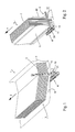
- Fig. 2 illustrates the book block 3 standing on its back, which is formed by the edges of the sheet 2.
- the driver 5 passes through two lateral, the conveying channel 1 forming guide walls 9, 10, in which slot-like recesses 11, 12 are provided.
- Fig. 3 shows the driver 5 in the position shown in FIG. 2, wherein as a traction means 4 a multi-membered, simple roller chain is provided.
- the latter consists of inner 13 and outer members 14, the tabs 15, 16 are fixedly connected by bolts 17 and sleeves 18.
- an outer plate 16 is replaced by a bearing block 20, which serves to receive the driver 5.
- a mounting plate 21 is provided on the bearing block 20, in which two bolts 17 of the outer member 14 riveted one end to the support plate 21 of the bearing block 20 and the other end are releasably secured by a spring clip 22.
- the trained as an attachment point for the driver 5 bearing block 20 is provided with a conveying direction F extending pivot axis 23, on which the driver 5 in a transverse to the conveying direction F pivotally, for example, actuated by a control cam, is mounted. In the present case, the slot 7 in the channel bottom 8 respectively.
- the driver 5 is formed by an effective, the book blocks 3 on the rear side abutting finger 24 and the latter has a adjacent to the predetermined breaking area U-shaped cross-section, the legs 25, 26 extending counter to the conveying direction F.
- the legs 25, 26 are tapered in the longitudinal direction of the driver finger 24, at least on a portion 27 after the predetermined breaking region 28.
- spaced connecting webs 29 with a arranged on the pivot axis 23 hub 30 of the driver 5 is connected (see Fig. 4).
- the driver 5 is through the hub 30 with the train on the respectively.
- the connection of the driver 5 with the bearing block 20 is effected by a plug pin 31, the two spaced in the conveying direction F bearing webs 32, 33 of the bearing block 20 and the hub 30 of the driver 5 arranged therebetween the pivot axis 23 forming passes through (see FIG. 6 in particular).
- the locking pin 31 is on the one hand designed so that it can be pushed through only by a bearing block end and on the other hand only at one end of the hub 30 by both parts. This can be achieved that the driver 5 is used in a change to the correct functional position and the locking pin 31 is secured to the designated bearing web 32.
- the hub 30 of the driver 5 has a bore 34 which has the larger diameter at the insertion end 35 for the locking pin 31 than at the outlet end 36. Accordingly, the insertion of the bearing web 33 is formed larger than the outlet opening of the bearing block 20 at its opposite end.
- an eye 37 is attached to the exit side bearing bar 32, which forms part of a locking device 41 for preventing displacement of the plug pin 31 from the operating position in the direction of the gravity axis 23. Furthermore, a circular groove 38 in a bore 39 of the eye 37 and an inserted into the groove 38 snap ring 40 which engages in an annular groove 41 on the locking pin 31, the other essential parts of the locking device 41st So that the locking pin 31 can be easily inserted into the different bore diameter, it is frusto-conical at the front end.
- the driver 5 is preferably formed of plastic injection molding, which has a nose 42 at the free end for reinforcement.
Landscapes
- Engineering & Computer Science (AREA)
- Mechanical Engineering (AREA)
- Feeding Of Articles By Means Other Than Belts Or Rollers (AREA)
- Basic Packing Technique (AREA)
- Auxiliary Devices For And Details Of Packaging Control (AREA)
- Separation, Sorting, Adjustment, Or Bending Of Sheets To Be Conveyed (AREA)
- Discharge By Other Means (AREA)
Abstract
Description
Zu diesem Zweck weist die Zusammentragmaschine an einem umlaufenden Zugmittel befestigte, in den Förderkanal ragende Mitnehmer auf, die beim Bilden der losen Buchblocks diese an der sog. Kopf- oder Fussskante des Buchblocks stossend anliegend transportieren. Dabei wird der Buchblock durch ein Aufstellelement in einer quer zur Förderrichtung senkrechten Ebene um etwa 90° gedreht, so dass er auf dem Rücken stehend den Klebebinder erreicht.
Auf diesem Förderabschnitt passiert der Buchblock das sich in Förderrichtung etwa nach einer Schraubenlinie windende Aufstellelement, wo der Buchblock auf den Rücken gestellt und der Mitnehmer durch einen Führungsschlitz sukzessive in eine horizontale Lage umgelegt wird.
- Fig. 1
- eine auszugsweise räumliche Darstellung eines Förderkanals einer Zusammentragmaschine,
- Fig. 2
- eine auszugsweise räumliche Darstellung des Förderkanals in Förderrichtung nach einem Aufstellelement,
- Fig. 3
- eine auszugsweise Draufsicht auf ein Förderorgan, bestehend aus Zugmittel und daran befestigtem Mitnehmer,
- Fig. 4
- einen Querschnitt nach Linie IV - IV in Fig. 3 durch einen Sollbruchbereich des Mitnehmers,
- Fig. 5
- einen Querschnitt nach Linie V - V in Fig. 3 durch den Mitnehmer und
- Fig. 6
- einen auszugsweisen Längsschnitt in Förderrichtung durch das Förderorgan.
Am Ende der Zusammentragstrecke windet sich der Förderkanal 1 in der Förderrichtung um etwa 90°, sodass der Buchblock 3 auf den gefalzten Rücken der Druckbogen 2 steht und durch den ebenfalls um 90° gedrehten Mitnehmer 5 weitertransportiert wird. Fig. 2 veranschaulicht den Buchblock 3 stehend auf seinem Rücken, der durch die Kanten der Druckbogen 2 gebildet wird. Der Mitnehmer 5 durchsetzt zwei seitliche, den Förderkanal 1 bildende Führungswände 9, 10, in denen schlitzartige Ausnehmungen 11, 12 vorgesehen sind.
Fig. 3 zeigt den Mitnehmer 5 in der Lage nach Fig. 2, wobei als Zugmittel 4 eine mehrgliedrige, einfache Rollenkette vorgesehen ist. Letztere besteht aus Innen- 13 und Aussengliedern 14, deren Laschen 15, 16 durch Bolzen 17 bzw. Hülsen 18 fest verbunden sind. Auf den Hülsen 18 sind frei drehbare, hohle Rollen 19 gelagert.
An der Befestigungsstelle des Mitnehmers 5, wozu ein Aussenglied 14 benutzt wird, wird eine Aussenlasche 16 durch einen Lagerbock 20 ersetzt, der zur Aufnahme des Mitnehmers 5 dient. Zu diesem Zweck ist am Lagerbock 20 eine Befestigungsplatte 21 vorgesehen, in der zwei Bolzen 17 des Aussengliedes 14 einenends mit der Halteplatte 21 des Lagerbocks 20 vernietet und anderenends durch einen Federbügel 22 lösbar gesichert sind. Der als Befestigungsstelle für den Mitnehmer 5 ausgebildete Lagerbock 20 ist mit einer in Förderrichtung F sich erstreckenden Schwenkachse 23 versehen, an der der Mitnehmer 5 in einer quer zur Förderrichtung F stehenden Ebene schwenkbar, beispielsweise durch eine Steuerkurve betätigbar, gelagert ist. Im vorliegenden Fall bilden der Schlitz 7 im Kanalboden 8 resp. die Ausnehmungen 11, 12 der Führungswände 9, 10 die Steuerkurve, durch die der Mitnehmer 5 geführt ist. Der Mitnehmer 5 ist durch einen förderwirksamen, die Buchblocks 3 an der rückwärtigen Seite stossenden Finger 24 ausgebildet und letzterer weist einen an den Sollbruchbereich angrenzenden U-förmigen Querschnitt auf, dessen Schenkel 25, 26 sich entgegen der Förderrichtung F erstrecken. Die Schenkel 25, 26 sind in Längserstreckungsrichtung des Mitnehmerfingers 24 sich verjüngend ausgebildet, zumindest auf einem Teilabschnitt 27 nach dem Sollbruchbereich 28. Im Sollbruchbereich 28 ist der Mitnehmerfinger 24 durch quer zur Förderrichtung F verlaufende, beabstandete Verbindungsstege 29 mit einer an der Schwenkachse 23 angeordneten Nabe 30 des Mitnehmers 5 verbunden (siehe Fig. 4).
Der Mitnehmer 5 ist durch die Nabe 30 mit dem am Zugmittel resp. der Rollenkette 4 befestigten Lagerbock 20 verbunden. Die Verbindung des Mitnehmers 5 mit dem Lagerbock 20 erfolgt durch einen Steckbolzen 31, der zwei in Förderrichtung F beabstandete Lagerstege 32, 33 des Lagerbocks 20 und die dazwischen angeordnete Nabe 30 des Mitnehmers 5 die Schwenkachse 23 bildend durchsetzt (siehe Fig. 6 insbesondere).
Der Steckbolzen 31 ist einerseits so ausgebildet, dass er ausschliesslich von einem Lagerbockende aus und andererseits nur an einem Ende der Nabe 30 durch beide Teile durchgesteckt werden kann. Damit kann erreicht werden, dass der Mitnehmer 5 bei einem Wechsel in die richtige Funktionslage eingesetzt und der Steckbolzen 31 an dem dafür vorgesehenen Lagersteg 32 gesichert wird. Hierzu weist die Nabe 30 des Mitnehmers 5 eine Bohrung 34 auf, die am Einsteckende 35 für den Steckbolzen 31 den grösseren Durchmesser als am Austrittsende 36 aufweist. Dementsprechend ist die Einstecköffnung des Lagerstegs 33 grösser ausgebildet als die Austrittsöffnung des Lagerbocks 20 an dessen gegenüberliegenden Ende.
Damit der Steckbolzen 31 leicht in die unterschiedlichen Bohrungsdurchmesser eingeführt werden kann, ist er am vorderen Ende kegelstumpfförmig ausgebildet.
Der Mitnehmer 5 ist vorzugsweise ein aus Kunststoff gebildeter Spritzling, der am freien Ende zur Verstärkung eine Nase 42 aufweist.
Claims (14)
- Vorrichtung zum Fördern von Buchblocks (3) auf einer Förderstrecke einer Einrichtung zur Herstellung von Büchern, Zeitschriften oder dgl., entlang welcher Förderstrecke ein umlaufendes, mit an einem Zugmittel (4) befestigten und quer zur Förderrichtung (F) in einen Förderkanal (1) ragenden, fingerartigen Mitnehmern (5) ausgebildetes, die Buchblocks (3) transportierendes Förderorgan angeordnet ist, dadurch gekennzeichnet, dass der fingerartig ausgebildete Mitnehmer (5) einen im Abstand zur Befestigungsstelle angeordneten Sollbruchbereich aufweist.
- Vorrichtung nach Anspruch 1, für das Bilden loser Buchblocks (3) durch Zusammentragen von Druckprodukten auf einer Förderstrecke, entlang welcher einen Förderkanal (1) mit Druckprodukten beschickende Anleger und ein die Buchblocks (3) transportierendes Förderorgan angeordnet sind.
- Vorrichtung nach Anspruch 1 oder 2, dadurch gekennzeichnet, dass die Befestigungsstelle durch eine Schwenkachse (23) des Mitnehmers (5) ausgebildet ist.
- Einrichtung nach einem der Ansprüche 1 bis 3,
dadurch gekennzeichnet, dass der Mitnehmerfinger (24) einen an den Sollbruchbereich anschliessenden U-förmigen Querschnitt aufweist. - Einrichtung nach Anspruch 4, dadurch gekennzeichnet, dass die Schenkel (25, 26) des U-förmigen Querschnitts sich entgegen der Förderrichtung (F) erstrecken.
- Einrichtung nach einem der Ansprüche 1 bis 3,
dadurch gekennzeichnet, dass die Schenkel (25, 26) des Mitnehmerfingers (24) in Längserstreckungsrichtung sich verjüngend ausgebildet sind. - Einrichtung nach einem der Ansprüche 4 bis 6,
dadurch gekennzeichnet, dass der Mitnehmerfinger (24) im Sollbruchbereich durch quer zur Förderrichtung (F) verlaufende Verbindungsstege (29) mit einer an der Schwenkachse (23) angeordneten Nabe (30) des Mitnehmers (5) verbunden ist. - Einrichtung nach Anspruch 7, dadurch gekennzeichnet, dass der Mitnehmer (5) durch die Nabe (30) an einem mit dem Zugmittel (4) verbundenen Lagerbock (20) angeordnet ist.
- Einrichtung nach Anspruch 8, mit einem als Rollenkette ausgebildeten Zugmittel (4), dadurch gekennzeichnet, dass der Lagerbock (20) durch eine als Aussenlasche (16) eines Kettengliedes (14) ausgebildete Befestigungsplatte (21) an der Rollenkette befestigt ist.
- Einrichtung nach Anspruch 9, dadurch gekennzeichnet, dass die Befestigungsplatte (21) Teil eines Kettenschlosses bildet.
- Einrichtung nach einem der Ansprüche 8 bis 10,
dadurch gekennzeichnet, dass der Lagerbock (20) zwei beabstandete, quer zur Förderrichtung (F) gerichtete Lagerstege (32, 33) aufweist, zwischen denen die Nabe (30) eines Mitnehmers (5) an einem die Lagerstege (32, 33) durchsetzenden Steckbolzen (31) gelagert ist. - Einrichtung nach Anspruch 11, dadurch gekennzeichnet, dass das vordere Steckbolzenende einen geringeren Durchmesser aufweist als das hintere Steckbolzenende.
- Einrichtung nach Anspruch 11, dadurch gekennzeichnet, dass den Steckbolzenenden unterschiedliche Bohrungen (35, 36) in der Nabe (30) des Mitnehmers (5) und den Lagerstegen (32, 33) des Lagerbocks (20) zugeordnet sind.
- Einrichtung nach einem der Ansprüche 11 bis 13, dadurch gekennzeichnet, dass zur achsialen Arretierung des Steckbolzens (31) zwischen diesem und dem Lagerbock (20) eine Arretiervorrichtung vorgesehen ist.
Priority Applications (4)
| Application Number | Priority Date | Filing Date | Title |
|---|---|---|---|
| DE502004007482T DE502004007482D1 (de) | 2004-03-11 | 2004-03-11 | Förderstrecke für Buchblocks in einer Einrichtung zur Herstellung gebundener Druckerzeugnisse |
| EP04405141A EP1574356B1 (de) | 2004-03-11 | 2004-03-11 | Förderstrecke für Buchblocks in einer Einrichtung zur Herstellung gebundener Druckerzeugnisse |
| AT04405141T ATE399649T1 (de) | 2004-03-11 | 2004-03-11 | Förderstrecke für buchblocks in einer einrichtung zur herstellung gebundener druckerzeugnisse |
| US11/077,094 US7410157B2 (en) | 2004-03-11 | 2005-03-10 | Device for conveying book blocks on a conveying line of a machine for producing books, magazines, or the like |
Applications Claiming Priority (1)
| Application Number | Priority Date | Filing Date | Title |
|---|---|---|---|
| EP04405141A EP1574356B1 (de) | 2004-03-11 | 2004-03-11 | Förderstrecke für Buchblocks in einer Einrichtung zur Herstellung gebundener Druckerzeugnisse |
Publications (2)
| Publication Number | Publication Date |
|---|---|
| EP1574356A1 true EP1574356A1 (de) | 2005-09-14 |
| EP1574356B1 EP1574356B1 (de) | 2008-07-02 |
Family
ID=34814452
Family Applications (1)
| Application Number | Title | Priority Date | Filing Date |
|---|---|---|---|
| EP04405141A Revoked EP1574356B1 (de) | 2004-03-11 | 2004-03-11 | Förderstrecke für Buchblocks in einer Einrichtung zur Herstellung gebundener Druckerzeugnisse |
Country Status (4)
| Country | Link |
|---|---|
| US (1) | US7410157B2 (de) |
| EP (1) | EP1574356B1 (de) |
| AT (1) | ATE399649T1 (de) |
| DE (1) | DE502004007482D1 (de) |
Families Citing this family (5)
| Publication number | Priority date | Publication date | Assignee | Title |
|---|---|---|---|---|
| US8210512B2 (en) * | 2009-09-03 | 2012-07-03 | Mueller Martini Holding Ag | Arrangement for the timed processing of a printed product with the aid of a transfer device |
| US8393608B2 (en) * | 2011-04-26 | 2013-03-12 | Xerox Corporation | Sheet finishing system including dual sheet stacking |
| JP6152532B2 (ja) * | 2013-07-30 | 2017-06-28 | 芳野マシナリー株式会社 | 製本装置 |
| CN103950314A (zh) * | 2014-04-23 | 2014-07-30 | 江苏凤凰盐城印刷有限公司 | 一种异形开本典藏书装订工艺 |
| CN115676293B (zh) * | 2022-10-14 | 2025-05-06 | 华能煤炭技术研究有限公司 | 一种链传动装置 |
Citations (8)
| Publication number | Priority date | Publication date | Assignee | Title |
|---|---|---|---|---|
| GB682669A (en) * | 1949-02-10 | 1952-11-12 | James Burn And Company Ltd | Improvements in and relating to book binding machinery |
| US2895148A (en) * | 1952-04-30 | 1959-07-21 | Brock & Rankin Inc | Continuous-flow rounding, jointing, and casing-in machinery |
| US3418947A (en) * | 1966-08-01 | 1968-12-31 | Mechanical Handling Sys Inc | Overload release for a conveyor drive and the like |
| US3503489A (en) * | 1967-08-08 | 1970-03-31 | Miehle Goss Dexter Inc | Conveyor |
| DE3116679A1 (de) * | 1980-05-10 | 1982-01-28 | E.C.H. Will (Gmbh & Co), 2000 Hamburg | Transportfinger eines sich laengs einer foerderbahn erstreckenden transportsystems |
| GB2147569A (en) * | 1983-09-09 | 1985-05-15 | Lawhill Design & Engineering S | Stack handling control |
| DE4012084A1 (de) * | 1990-04-14 | 1991-10-17 | Kolbus Gmbh & Co Kg | Buchblocktransportkanal |
| EP1232879A1 (de) * | 2001-02-15 | 2002-08-21 | Wohlenberg Buchbindesysteme GmbH | Einfuhrvorrichtung zum Transportieren von Buchblöcken in eine Folgemaschine |
Family Cites Families (4)
| Publication number | Priority date | Publication date | Assignee | Title |
|---|---|---|---|---|
| US4549729A (en) * | 1983-01-18 | 1985-10-29 | Ga-Vehren Engineering Company | Overlap conveyor apparatus |
| DE3713036A1 (de) * | 1987-01-21 | 1988-08-04 | Kolbus Gmbh & Co Kg | Vorsatzklebeeinrichtung fuer klebebindemaschine |
| DE3840816C2 (de) * | 1988-12-03 | 1999-05-27 | Kolbus Gmbh & Co Kg | Einfuhrvorrichtung zum Transportieren von Buchblocks in eine Folgemaschine |
| DE19616047C5 (de) * | 1996-04-23 | 2011-04-21 | Kolbus Gmbh & Co. Kg | Zusammentragmaschine |
-
2004
- 2004-03-11 DE DE502004007482T patent/DE502004007482D1/de not_active Expired - Lifetime
- 2004-03-11 AT AT04405141T patent/ATE399649T1/de not_active IP Right Cessation
- 2004-03-11 EP EP04405141A patent/EP1574356B1/de not_active Revoked
-
2005
- 2005-03-10 US US11/077,094 patent/US7410157B2/en not_active Expired - Fee Related
Patent Citations (8)
| Publication number | Priority date | Publication date | Assignee | Title |
|---|---|---|---|---|
| GB682669A (en) * | 1949-02-10 | 1952-11-12 | James Burn And Company Ltd | Improvements in and relating to book binding machinery |
| US2895148A (en) * | 1952-04-30 | 1959-07-21 | Brock & Rankin Inc | Continuous-flow rounding, jointing, and casing-in machinery |
| US3418947A (en) * | 1966-08-01 | 1968-12-31 | Mechanical Handling Sys Inc | Overload release for a conveyor drive and the like |
| US3503489A (en) * | 1967-08-08 | 1970-03-31 | Miehle Goss Dexter Inc | Conveyor |
| DE3116679A1 (de) * | 1980-05-10 | 1982-01-28 | E.C.H. Will (Gmbh & Co), 2000 Hamburg | Transportfinger eines sich laengs einer foerderbahn erstreckenden transportsystems |
| GB2147569A (en) * | 1983-09-09 | 1985-05-15 | Lawhill Design & Engineering S | Stack handling control |
| DE4012084A1 (de) * | 1990-04-14 | 1991-10-17 | Kolbus Gmbh & Co Kg | Buchblocktransportkanal |
| EP1232879A1 (de) * | 2001-02-15 | 2002-08-21 | Wohlenberg Buchbindesysteme GmbH | Einfuhrvorrichtung zum Transportieren von Buchblöcken in eine Folgemaschine |
Also Published As
| Publication number | Publication date |
|---|---|
| ATE399649T1 (de) | 2008-07-15 |
| US7410157B2 (en) | 2008-08-12 |
| EP1574356B1 (de) | 2008-07-02 |
| DE502004007482D1 (de) | 2008-08-14 |
| US20050201849A1 (en) | 2005-09-15 |
Similar Documents
| Publication | Publication Date | Title |
|---|---|---|
| AT397370B (de) | Vorrichtung zum sammeln von gefalzten druckbogen | |
| EP1914182B1 (de) | Zuführ-Transport-System für Bügel mit darauf hängenden Gegenständen | |
| EP0346578A1 (de) | Einrichtung zum Sammeln, Zusammentragen und Einstecken von Druckereiprodukten | |
| EP0341425A2 (de) | Einrichtung zum Sammeln von gefalzten Druckbogen | |
| EP0473902B1 (de) | Vorrichtung zum Drahtheften von mehrteiligen Druckereierzeugnissen | |
| DE19922844B4 (de) | Blindnietenhalter | |
| EP2385005A1 (de) | Förderstrecke zum Transport von Artikeln | |
| DE102012019524A1 (de) | Aufnahmevorrichtung zur Aufnahme von Artikeln der Tabak verarbeitenden Industrie | |
| EP1574356B1 (de) | Förderstrecke für Buchblocks in einer Einrichtung zur Herstellung gebundener Druckerzeugnisse | |
| DE102007053490A1 (de) | Sammelhefter mit variabler Kettenteilung | |
| EP4405281B1 (de) | Vereinzelungsvorrichtung für profile | |
| EP0346579A1 (de) | Einrichtung zum Sammeln, Zusammentragen und Einstecken von Druckereiprodukten | |
| DE540602C (de) | Zubringevorrichtung, insbesondere fuer Packmaschinen | |
| DE102010035126A1 (de) | Verfahren und Vorrichtung zum kontrollierten Übergeben eines Stückguts von einem Zuführförderer auf einen Förderer | |
| EP1418146B1 (de) | Vorrichtung zum Sammeln und Bearbeiten von gefalteten Druckprodukten | |
| EP2007667B1 (de) | Verfahren und vorrichtung zum zugeben je einer beilage zu gefalteten oder gebundenen druckprodukten | |
| EP0903308B1 (de) | Zellenrad zur Uebergabe von Gegenständen von einem ersten Fördermittel an ein zweites Fördermittel | |
| EP1315618B1 (de) | Verfahren zum einziehen von mehreren aus einer bahn bildbaren teilbahnen | |
| EP1270476B1 (de) | Einrichtung zum Transport von Druckprodukten | |
| CH690576A5 (de) | Vorrichtung zum Verarbeiten von Druckereiprodukten. | |
| EP2284107B1 (de) | Vorrichtung und Verfahren zum Übergeben von Druckbogen | |
| EP1588861B1 (de) | Verfahren und Einrichtung zum Anbringen eines zumindest annähernd flächigen Ergänzungsproduktes an einer Seitenfläche eines Druckerzeugnisses | |
| EP0573390B1 (de) | Einsteckmaschine | |
| EP1767478B1 (de) | Mitnehmerelement und Sammelkette | |
| EP1802541B1 (de) | Gurtträger für schlauchförderer |
Legal Events
| Date | Code | Title | Description |
|---|---|---|---|
| PUAI | Public reference made under article 153(3) epc to a published international application that has entered the european phase |
Free format text: ORIGINAL CODE: 0009012 |
|
| AK | Designated contracting states |
Kind code of ref document: A1 Designated state(s): AT BE BG CH CY CZ DE DK EE ES FI FR GB GR HU IE IT LI LU MC NL PL PT RO SE SI SK TR |
|
| AX | Request for extension of the european patent |
Extension state: AL LT LV MK |
|
| 17P | Request for examination filed |
Effective date: 20060116 |
|
| AKX | Designation fees paid |
Designated state(s): AT BE BG CH CY CZ DE DK EE ES FI FR GB GR HU IE IT LI LU MC NL PL PT RO SE SI SK TR |
|
| 17Q | First examination report despatched |
Effective date: 20060801 |
|
| GRAP | Despatch of communication of intention to grant a patent |
Free format text: ORIGINAL CODE: EPIDOSNIGR1 |
|
| GRAS | Grant fee paid |
Free format text: ORIGINAL CODE: EPIDOSNIGR3 |
|
| GRAA | (expected) grant |
Free format text: ORIGINAL CODE: 0009210 |
|
| AK | Designated contracting states |
Kind code of ref document: B1 Designated state(s): AT BE BG CH CY CZ DE DK EE ES FI FR GB GR HU IE IT LI LU MC NL PL PT RO SE SI SK TR |
|
| REG | Reference to a national code |
Ref country code: GB Ref legal event code: FG4D Free format text: NOT ENGLISH |
|
| REG | Reference to a national code |
Ref country code: CH Ref legal event code: EP |
|
| REF | Corresponds to: |
Ref document number: 502004007482 Country of ref document: DE Date of ref document: 20080814 Kind code of ref document: P |
|
| REG | Reference to a national code |
Ref country code: IE Ref legal event code: FG4D Free format text: LANGUAGE OF EP DOCUMENT: GERMAN |
|
| PG25 | Lapsed in a contracting state [announced via postgrant information from national office to epo] |
Ref country code: SI Free format text: LAPSE BECAUSE OF FAILURE TO SUBMIT A TRANSLATION OF THE DESCRIPTION OR TO PAY THE FEE WITHIN THE PRESCRIBED TIME-LIMIT Effective date: 20080702 |
|
| PG25 | Lapsed in a contracting state [announced via postgrant information from national office to epo] |
Ref country code: NL Free format text: LAPSE BECAUSE OF FAILURE TO SUBMIT A TRANSLATION OF THE DESCRIPTION OR TO PAY THE FEE WITHIN THE PRESCRIBED TIME-LIMIT Effective date: 20080702 |
|
| NLV1 | Nl: lapsed or annulled due to failure to fulfill the requirements of art. 29p and 29m of the patents act | ||
| PG25 | Lapsed in a contracting state [announced via postgrant information from national office to epo] |
Ref country code: PT Free format text: LAPSE BECAUSE OF FAILURE TO SUBMIT A TRANSLATION OF THE DESCRIPTION OR TO PAY THE FEE WITHIN THE PRESCRIBED TIME-LIMIT Effective date: 20081202 Ref country code: ES Free format text: LAPSE BECAUSE OF FAILURE TO SUBMIT A TRANSLATION OF THE DESCRIPTION OR TO PAY THE FEE WITHIN THE PRESCRIBED TIME-LIMIT Effective date: 20081013 |
|
| REG | Reference to a national code |
Ref country code: IE Ref legal event code: FD4D |
|
| PG25 | Lapsed in a contracting state [announced via postgrant information from national office to epo] |
Ref country code: BG Free format text: LAPSE BECAUSE OF FAILURE TO SUBMIT A TRANSLATION OF THE DESCRIPTION OR TO PAY THE FEE WITHIN THE PRESCRIBED TIME-LIMIT Effective date: 20081002 Ref country code: FI Free format text: LAPSE BECAUSE OF FAILURE TO SUBMIT A TRANSLATION OF THE DESCRIPTION OR TO PAY THE FEE WITHIN THE PRESCRIBED TIME-LIMIT Effective date: 20080702 |
|
| PLBI | Opposition filed |
Free format text: ORIGINAL CODE: 0009260 |
|
| PG25 | Lapsed in a contracting state [announced via postgrant information from national office to epo] |
Ref country code: EE Free format text: LAPSE BECAUSE OF FAILURE TO SUBMIT A TRANSLATION OF THE DESCRIPTION OR TO PAY THE FEE WITHIN THE PRESCRIBED TIME-LIMIT Effective date: 20080702 Ref country code: DK Free format text: LAPSE BECAUSE OF FAILURE TO SUBMIT A TRANSLATION OF THE DESCRIPTION OR TO PAY THE FEE WITHIN THE PRESCRIBED TIME-LIMIT Effective date: 20080702 Ref country code: IE Free format text: LAPSE BECAUSE OF FAILURE TO SUBMIT A TRANSLATION OF THE DESCRIPTION OR TO PAY THE FEE WITHIN THE PRESCRIBED TIME-LIMIT Effective date: 20080702 |
|
| PLAX | Notice of opposition and request to file observation + time limit sent |
Free format text: ORIGINAL CODE: EPIDOSNOBS2 |
|
| 26 | Opposition filed |
Opponent name: KOLBUS GMBH & CO. KG Effective date: 20090330 |
|
| PG25 | Lapsed in a contracting state [announced via postgrant information from national office to epo] |
Ref country code: RO Free format text: LAPSE BECAUSE OF FAILURE TO SUBMIT A TRANSLATION OF THE DESCRIPTION OR TO PAY THE FEE WITHIN THE PRESCRIBED TIME-LIMIT Effective date: 20080702 Ref country code: CZ Free format text: LAPSE BECAUSE OF FAILURE TO SUBMIT A TRANSLATION OF THE DESCRIPTION OR TO PAY THE FEE WITHIN THE PRESCRIBED TIME-LIMIT Effective date: 20080702 Ref country code: SK Free format text: LAPSE BECAUSE OF FAILURE TO SUBMIT A TRANSLATION OF THE DESCRIPTION OR TO PAY THE FEE WITHIN THE PRESCRIBED TIME-LIMIT Effective date: 20080702 |
|
| PGFP | Annual fee paid to national office [announced via postgrant information from national office to epo] |
Ref country code: GB Payment date: 20090324 Year of fee payment: 6 |
|
| PGFP | Annual fee paid to national office [announced via postgrant information from national office to epo] |
Ref country code: IT Payment date: 20090318 Year of fee payment: 6 |
|
| PLBB | Reply of patent proprietor to notice(s) of opposition received |
Free format text: ORIGINAL CODE: EPIDOSNOBS3 |
|
| BERE | Be: lapsed |
Owner name: MULLER MARTINI HOLDING A.G. Effective date: 20090331 |
|
| PG25 | Lapsed in a contracting state [announced via postgrant information from national office to epo] |
Ref country code: MC Free format text: LAPSE BECAUSE OF NON-PAYMENT OF DUE FEES Effective date: 20090331 |
|
| PGFP | Annual fee paid to national office [announced via postgrant information from national office to epo] |
Ref country code: CH Payment date: 20090626 Year of fee payment: 6 Ref country code: FR Payment date: 20090130 Year of fee payment: 6 |
|
| PG25 | Lapsed in a contracting state [announced via postgrant information from national office to epo] |
Ref country code: SE Free format text: LAPSE BECAUSE OF FAILURE TO SUBMIT A TRANSLATION OF THE DESCRIPTION OR TO PAY THE FEE WITHIN THE PRESCRIBED TIME-LIMIT Effective date: 20081002 |
|
| PG25 | Lapsed in a contracting state [announced via postgrant information from national office to epo] |
Ref country code: BE Free format text: LAPSE BECAUSE OF NON-PAYMENT OF DUE FEES Effective date: 20090331 |
|
| PLCK | Communication despatched that opposition was rejected |
Free format text: ORIGINAL CODE: EPIDOSNREJ1 |
|
| PG25 | Lapsed in a contracting state [announced via postgrant information from national office to epo] |
Ref country code: PL Free format text: LAPSE BECAUSE OF FAILURE TO SUBMIT A TRANSLATION OF THE DESCRIPTION OR TO PAY THE FEE WITHIN THE PRESCRIBED TIME-LIMIT Effective date: 20080702 |
|
| PG25 | Lapsed in a contracting state [announced via postgrant information from national office to epo] |
Ref country code: AT Free format text: LAPSE BECAUSE OF NON-PAYMENT OF DUE FEES Effective date: 20090311 |
|
| APBM | Appeal reference recorded |
Free format text: ORIGINAL CODE: EPIDOSNREFNO |
|
| APBP | Date of receipt of notice of appeal recorded |
Free format text: ORIGINAL CODE: EPIDOSNNOA2O |
|
| APAH | Appeal reference modified |
Free format text: ORIGINAL CODE: EPIDOSCREFNO |
|
| APBQ | Date of receipt of statement of grounds of appeal recorded |
Free format text: ORIGINAL CODE: EPIDOSNNOA3O |
|
| PG25 | Lapsed in a contracting state [announced via postgrant information from national office to epo] |
Ref country code: GR Free format text: LAPSE BECAUSE OF FAILURE TO SUBMIT A TRANSLATION OF THE DESCRIPTION OR TO PAY THE FEE WITHIN THE PRESCRIBED TIME-LIMIT Effective date: 20081003 |
|
| REG | Reference to a national code |
Ref country code: CH Ref legal event code: PL |
|
| GBPC | Gb: european patent ceased through non-payment of renewal fee |
Effective date: 20100311 |
|
| REG | Reference to a national code |
Ref country code: FR Ref legal event code: ST Effective date: 20101130 |
|
| PG25 | Lapsed in a contracting state [announced via postgrant information from national office to epo] |
Ref country code: FR Free format text: LAPSE BECAUSE OF NON-PAYMENT OF DUE FEES Effective date: 20100331 |
|
| PG25 | Lapsed in a contracting state [announced via postgrant information from national office to epo] |
Ref country code: LI Free format text: LAPSE BECAUSE OF NON-PAYMENT OF DUE FEES Effective date: 20100331 Ref country code: CH Free format text: LAPSE BECAUSE OF NON-PAYMENT OF DUE FEES Effective date: 20100331 |
|
| PG25 | Lapsed in a contracting state [announced via postgrant information from national office to epo] |
Ref country code: GB Free format text: LAPSE BECAUSE OF NON-PAYMENT OF DUE FEES Effective date: 20100311 Ref country code: IT Free format text: LAPSE BECAUSE OF NON-PAYMENT OF DUE FEES Effective date: 20100311 |
|
| PG25 | Lapsed in a contracting state [announced via postgrant information from national office to epo] |
Ref country code: LU Free format text: LAPSE BECAUSE OF NON-PAYMENT OF DUE FEES Effective date: 20090311 |
|
| PG25 | Lapsed in a contracting state [announced via postgrant information from national office to epo] |
Ref country code: HU Free format text: LAPSE BECAUSE OF FAILURE TO SUBMIT A TRANSLATION OF THE DESCRIPTION OR TO PAY THE FEE WITHIN THE PRESCRIBED TIME-LIMIT Effective date: 20090103 |
|
| PG25 | Lapsed in a contracting state [announced via postgrant information from national office to epo] |
Ref country code: TR Free format text: LAPSE BECAUSE OF FAILURE TO SUBMIT A TRANSLATION OF THE DESCRIPTION OR TO PAY THE FEE WITHIN THE PRESCRIBED TIME-LIMIT Effective date: 20080702 |
|
| PG25 | Lapsed in a contracting state [announced via postgrant information from national office to epo] |
Ref country code: CY Free format text: LAPSE BECAUSE OF FAILURE TO SUBMIT A TRANSLATION OF THE DESCRIPTION OR TO PAY THE FEE WITHIN THE PRESCRIBED TIME-LIMIT Effective date: 20080702 |
|
| PGFP | Annual fee paid to national office [announced via postgrant information from national office to epo] |
Ref country code: DE Payment date: 20140318 Year of fee payment: 11 |
|
| APBU | Appeal procedure closed |
Free format text: ORIGINAL CODE: EPIDOSNNOA9O |
|
| REG | Reference to a national code |
Ref country code: DE Ref legal event code: R103 Ref document number: 502004007482 Country of ref document: DE Ref country code: DE Ref legal event code: R064 Ref document number: 502004007482 Country of ref document: DE |
|
| RDAF | Communication despatched that patent is revoked |
Free format text: ORIGINAL CODE: EPIDOSNREV1 |
|
| RDAG | Patent revoked |
Free format text: ORIGINAL CODE: 0009271 |
|
| STAA | Information on the status of an ep patent application or granted ep patent |
Free format text: STATUS: PATENT REVOKED |
|
| 27W | Patent revoked |
Effective date: 20150410 |
|
| REG | Reference to a national code |
Ref country code: DE Ref legal event code: R107 Ref document number: 502004007482 Country of ref document: DE |