EP1574276A1 - Sägetisch für Platten oder ähnliches - Google Patents
Sägetisch für Platten oder ähnliches Download PDFInfo
- Publication number
- EP1574276A1 EP1574276A1 EP05290477A EP05290477A EP1574276A1 EP 1574276 A1 EP1574276 A1 EP 1574276A1 EP 05290477 A EP05290477 A EP 05290477A EP 05290477 A EP05290477 A EP 05290477A EP 1574276 A1 EP1574276 A1 EP 1574276A1
- Authority
- EP
- European Patent Office
- Prior art keywords
- table according
- foot
- martyrs
- frame
- cross
- Prior art date
- Legal status (The legal status is an assumption and is not a legal conclusion. Google has not performed a legal analysis and makes no representation as to the accuracy of the status listed.)
- Granted
Links
- 125000006850 spacer group Chemical group 0.000 claims abstract description 3
- 238000005259 measurement Methods 0.000 claims description 17
- 239000000463 material Substances 0.000 claims description 2
- 230000008901 benefit Effects 0.000 description 5
- 239000002023 wood Substances 0.000 description 3
- 230000000903 blocking effect Effects 0.000 description 2
- 238000010276 construction Methods 0.000 description 1
- 238000010586 diagram Methods 0.000 description 1
- 238000000034 method Methods 0.000 description 1
- 230000000284 resting effect Effects 0.000 description 1
- 239000011800 void material Substances 0.000 description 1
Images


Classifications
-
- B—PERFORMING OPERATIONS; TRANSPORTING
- B25—HAND TOOLS; PORTABLE POWER-DRIVEN TOOLS; MANIPULATORS
- B25H—WORKSHOP EQUIPMENT, e.g. FOR MARKING-OUT WORK; STORAGE MEANS FOR WORKSHOPS
- B25H1/00—Work benches; Portable stands or supports for positioning portable tools or work to be operated on thereby
- B25H1/08—Work benches; Portable stands or supports for positioning portable tools or work to be operated on thereby with provision for attachment of work holders
Definitions
- the present invention relates to tables for sawing, cutting, etc. of panels or the like, and more particularly the tables easily can be transported anywhere and can be used for many other functions.
- the present invention aims to make a saw table of panels or the like, which overcomes the disadvantages of similar tables known from the prior art and which meets the goals mentioned above.
- the present invention relates to a table for the sawing panels or the like according to the appended claim 1.
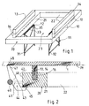
- the table according to the invention for sawing panels 1 or the like comprises a base 10 defining a work plane Pt, feet means 11 and means 12 for mounting these feet means in cooperation with the base 10.
- the table further comprises least two "martyrs" 13, 14, ... not located on the same axis, each martyr 13, 14 being constituted by a rod 15 made of a material capable of being easily cut by a saw blade 50 without damaging it, for example wood or analogous, the wand 15 having a substantially constant cross-section and of substantially rectangular shape throughout its length, the sections of two rods being furthermore substantially identical.
- the table therefore has in addition two grooves 16, 17 made on the same face 18 of the base 10 for receive respectively the two "martyrs" 13, 14, the width of these grooves being at least equal to the width of the cross section of the chopsticks, and their depth less than the length of this cross section.
- the two martyrs should not be located on the same axis, that is, they can not be collinear. They can be parallel, as illustrated in Figure 1, or between them an angle not null, so that they can define a support for a panel or the like and determine a lift polygon of a non-zero area. This is how are described below other embodiments in which, for safety, the lift polygon has a maximum area.
- the base 10 defined above is formed, Figures 1 and 3, a frame 20 consisting of longitudinal members 21, 22, ..., both grooves 16, 17 being respectively formed in two different longitudinal members 21, 22.
- the frame 20 has four spars substantially forming a rectangular figure or the like and delimiting an empty through space 23 whose function and benefits will be underlined below.
- the table comprises feet means 11. These feet means are constituted, as illustrated in FIGS. 1 and 3, by two feet 31, 32 formed of rods, plates or the like and the means 12 for mount these two feet 31, 32 in cooperation with the base 10 are constituted, for each foot, for example, by a hinge 33, 34 mounted in cooperation respectively with a spar 21, 22, ... and the upper end 35 of the foot.
- the hinge and the foot associated with it are arranged so that the foot is suitable for take two positions, a first position called “exit”, represented in lines interrupted in FIG. 3 and in continuous lines in FIG. 1, in which it is substantially perpendicular to the work plane Pt and a second position called “reentry”, shown in solid lines in Figure 3, in which it is substantially housed at least partially in the empty space 23 delimited by the frame 20.
- the table comprises at least one bar 40 and at least one spacer 41 to secure the bar on one side 42 of one 21 of the longitudinal members 21, 22, ..., of so that the bar is parallel to this side of the spar, at a non-zero distance of the latter and below the work plan Pt.
- the table could have several of these bars spread on the sides frame 20, but only one is sufficient in general.
- This bar 40 has essentially two advantages: it constitutes a handle for transporting the table, that it has a single frame 20 or two frames foldable on each other as described below, and it allows also to obtain an enlargement of the support of the panel to saw.
- the table then further comprises at least one cam 43 adapted to position in the space 44 between the bar 40 and the spar 21 to which it is associated, so that this cam 43 rests with its low end 45 below the spar 21 and its middle portion 46 on the bar 40, and that the face 48 of its upper end 47 is located substantially in the plane of Pt.
- the sawing panel 1 rests on the tops of the two matirs 13, 14, with an offset part resting on the face 48 of the upper end 47 of the cam 43.
- the means described above make it possible to maintain the panel substantially in a horizontal plane, even though it is flexible like a panel of wood or the like and of dimensions greater than those defined by all the martyrs 13, 14 on a frame 20.
- the depth of the gorges 16, 17 is substantially equal to half the length of the cross-section of the chopsticks defined above.
- the base 10 consists of a frame 20 as shown in FIG. 1.
- the table has only two martyrs 13, 14. But it is advantageous, to safely perform many cuts of all forms, that the table includes four martyrs mounted in cooperation in four grooves made respectively in the four longitudinal members.
- the four martyrs define a support defined along a closed line that is continuous or substantially continuous, avoiding that a flexible panel undergoes a curvature, as with the embodiment according to Figure 1 between the two martyrs 13 and 14, when one cut it.
- the table comprises a single 20.
- the table has at least two frames Advantageously identical, each formed of four longitudinal members, and means for mounting the two frames pivoting relative to each other so that they can fold one over the other, and unfold so as to form only one only work plan.
- Means to rotate the two frames relative to each other to the other will be mounted, for example, in cooperation with the spar opposite to the one on which is fixed the bar 40 described above.
- This height of cut H is determined so that when the pad 51 rubs on the face panel 1, it is greater than the thickness E of the panel and that, when the saw blade is moved to make the cut, part 52 of the blade emerging below the panel does not come into the spars 21, 22, ..., but only the upper part 53 of the martyrs 13, 14, ... which can be changed when they are too nicked.
- the rods forming the martyrs are determined so that the length L of their cross-section defined above satisfies the following relation: H ⁇ E + L - P.
- L 2P
- the rods forming the martyrs are determined so that the length L of their cross section verifies the following relation: 2H - E ⁇ L.
- the table according to the invention also has the following advantage: space void 23 delimited by the frame 20 may constitute a storage space for all the tools necessary for cutting the panels, for example clamps, pliers, saw blades, etc.
- the table according to the invention further comprises at least two sleepers 101, 102 mounted integral with the frame 20 between two side members 21, 22, ... opposite thereof so that they are substantially parallel to each other. It is even advantageous that other sleepers are provided, such as those that are represented between these two crosspieces 101, 102.
- the table also comprises at least two measurement rules 103, 104, each having graduations G, for example lines defining millimeters or the like, and means 110 to mount a first end 111, 112 of each of the two measurement rules 103, 104 in cooperation with respectively the frame 20 and the two cross members 101, 102.
- These means 110 may be of different types, for example a hook in solidarity with the rule that comes on a cross and one or more ratchets secured to the frame that block the rule on and / or in relation thereto.
- the table also includes a reference rule 120 which serves as a guide, for example to a circular saw or the like, to cut for example a P panel shown in broken bold lines in Figure 5.
- a reference rule 120 which serves as a guide, for example to a circular saw or the like, to cut for example a P panel shown in broken bold lines in Figure 5.
- fixing means 130 for setting this reference rule. above the first ends 111, 112 of the two measurement rules 103, 104 so that it is substantially perpendicular to these measurement rules.
- These fixing means 130 can also be of any type, but can advantageously consist of pins integral with these first ends and protruding above the two measuring rulers and orifices made in the reference rule 120 in which can dip the pins.
- a support rule 140 means 150 to mount it sliding above the two measurement rules 103, 104 so that it further comprises a projecting portion in the space 105 defined between these two measurement rules 103, 104, and means 160 for blocking this support rule 140 on the two measurement rules in a determined position between their ends.
- These means 150, 160 respectively of sliding assembly and of blocking the support rule 140 can be constituted by means of any type.
- they will be constituted by a groove in the tail dovetail or the like made in each measuring rule 103, 104 and a key whose head is slidably mounted in the groove and whose rod passes through the support rule 140, with means for locking together, the key, the rule of support that it goes through and the rule of measurement in which it slides in translation, for example a wing nut mounted screwed on the shaft of the key in depending on the support rule 140.
- a table according to the invention in the embodiment described above in Figure 5 is used as follows.
- the user can start by placing the two measurement rules 103, 104 by fixing them on the two sleepers 101, 102. It is clear that the length of these two measurement rules is determined to meet the usual needs in this area. On the Figure 5, these rules are of sufficient length to extend well beyond the frame 20.
- the user makes slide the support rule 140 to bring it to a position corresponding to the determined length, which is identified by the graduations G worn by the two measurement rules 103, 104, so that the distance separating the line of section L of the support rule 140 is equal to this determined length.
- the user can position one or more martyrs M on the sleepers auxiliaries like the two crosspieces 101, 102. It then positions the panel P to cut so that it comes to bear against the support rule 140, as illustrated in Figure 5. It should be noted that the panel is arranged in the space 105 delimited by the measurement rules 103, 104 whose height is determined from so that it is always greater than the thickness of the panels to be cut and that these panels come to bear on the part of the protruding support ruler in space 105.
Landscapes
- Engineering & Computer Science (AREA)
- Mechanical Engineering (AREA)
- Workshop Equipment, Work Benches, Supports, Or Storage Means (AREA)
- Laminated Bodies (AREA)
- Sawing (AREA)
- Polishing Bodies And Polishing Tools (AREA)
Applications Claiming Priority (2)
| Application Number | Priority Date | Filing Date | Title |
|---|---|---|---|
| FR0402414 | 2004-03-09 | ||
| FR0402414A FR2867410B1 (fr) | 2004-03-09 | 2004-03-09 | Table pour le sciage et la decoupe de panneaux ou analogues |
Publications (2)
| Publication Number | Publication Date |
|---|---|
| EP1574276A1 true EP1574276A1 (de) | 2005-09-14 |
| EP1574276B1 EP1574276B1 (de) | 2007-04-25 |
Family
ID=34814561
Family Applications (1)
| Application Number | Title | Priority Date | Filing Date |
|---|---|---|---|
| EP05290477A Expired - Lifetime EP1574276B1 (de) | 2004-03-09 | 2005-03-03 | Sägetisch für Platten oder ähnliches |
Country Status (4)
| Country | Link |
|---|---|
| EP (1) | EP1574276B1 (de) |
| AT (1) | ATE360499T1 (de) |
| DE (1) | DE602005000944D1 (de) |
| FR (1) | FR2867410B1 (de) |
Cited By (2)
| Publication number | Priority date | Publication date | Assignee | Title |
|---|---|---|---|---|
| US10792834B2 (en) | 2017-06-05 | 2020-10-06 | Milwaukee Electric Tool Corporation | Table saw |
| CN113752026A (zh) * | 2021-09-06 | 2021-12-07 | 中国一冶集团有限公司 | 一种建筑工程用建材切割装置 |
Families Citing this family (1)
| Publication number | Priority date | Publication date | Assignee | Title |
|---|---|---|---|---|
| CN116175703B (zh) * | 2023-03-07 | 2024-09-06 | 成都天骄家具有限公司 | 一种木料切割装置及其加工方法 |
Citations (1)
| Publication number | Priority date | Publication date | Assignee | Title |
|---|---|---|---|---|
| US5144994A (en) * | 1991-06-28 | 1992-09-08 | Stecker Sr David W | Portable universal saw table |
-
2004
- 2004-03-09 FR FR0402414A patent/FR2867410B1/fr not_active Expired - Fee Related
-
2005
- 2005-03-03 EP EP05290477A patent/EP1574276B1/de not_active Expired - Lifetime
- 2005-03-03 DE DE602005000944T patent/DE602005000944D1/de not_active Expired - Lifetime
- 2005-03-03 AT AT05290477T patent/ATE360499T1/de not_active IP Right Cessation
Patent Citations (1)
| Publication number | Priority date | Publication date | Assignee | Title |
|---|---|---|---|---|
| US5144994A (en) * | 1991-06-28 | 1992-09-08 | Stecker Sr David W | Portable universal saw table |
Cited By (3)
| Publication number | Priority date | Publication date | Assignee | Title |
|---|---|---|---|---|
| US10792834B2 (en) | 2017-06-05 | 2020-10-06 | Milwaukee Electric Tool Corporation | Table saw |
| US11407142B2 (en) | 2017-06-05 | 2022-08-09 | Milwaukee Electric Tool Corporation | Table saw |
| CN113752026A (zh) * | 2021-09-06 | 2021-12-07 | 中国一冶集团有限公司 | 一种建筑工程用建材切割装置 |
Also Published As
| Publication number | Publication date |
|---|---|
| EP1574276B1 (de) | 2007-04-25 |
| ATE360499T1 (de) | 2007-05-15 |
| DE602005000944D1 (de) | 2007-06-06 |
| FR2867410A1 (fr) | 2005-09-16 |
| FR2867410B1 (fr) | 2006-09-08 |
Similar Documents
| Publication | Publication Date | Title |
|---|---|---|
| FR2649633A1 (fr) | Table de sciage et etabli-etau | |
| WO2006095065A1 (fr) | Outil de coupe pour decouper une plaque | |
| WO1997036520A1 (fr) | Siege compose d'elements assemblables | |
| CA2371152A1 (fr) | Panneaux faits de pieces de bois emboitees | |
| EP1574276B1 (de) | Sägetisch für Platten oder ähnliches | |
| FR3024489A1 (fr) | Echelle telescopique comportant des troncons d'echelle de densites differentes | |
| CA1135516A (fr) | Chaine a un seul sens de courbure et application a une main courante | |
| FR2577843A1 (fr) | Systeme de butee pour scies circulaires a tables | |
| FR3004480A1 (fr) | Structure pliable de travail en encorbellement integrant un dispositif d'aide au depliage d'un auvent | |
| EP2868859B1 (de) | Zugangsvorrichtung mit regulierbarer Höhe | |
| FR3006168A1 (fr) | Cale osseuse distratante | |
| EP1052344B1 (de) | Bausatz zur Montage einer geraden Treppe und Montageverfahren unter Verwendung dieses Bausatzes | |
| FR3025739A1 (fr) | Lame pour un outil de decoupe de plaques | |
| EP3661392B1 (de) | Stützböcke | |
| FR2559657A1 (fr) | Dispositif support repliable formant en particulier table pliante | |
| FR2800587A1 (fr) | Table de type ayant au moins un pied ou pietinement repliable | |
| FR2511924A1 (fr) | Dispositif de scie circulaire | |
| FR2787688A1 (fr) | Meuble d'etageres | |
| FR2666620A1 (fr) | Echelle pliante. | |
| EP2532599A1 (de) | Palette zur aufrechten Halterung dünner flächiger Gegenstände | |
| EP2792581B1 (de) | Abmontierbare Halterungsstruktur von Karosserieelementen eines Kraftfahrzeugs | |
| FR2899217A1 (fr) | "ensemble constitue d'une contre-fleche et de son lest, pour grue a tour" | |
| FR2491420A1 (fr) | Chariot individuel repliable | |
| EP0761355A1 (de) | Handsäge mit Sägeblatthaltevorrichtung | |
| EP0759833B1 (de) | Führungsvorrichtung für tragbare elektrische schneidvorrichtung |
Legal Events
| Date | Code | Title | Description |
|---|---|---|---|
| PUAI | Public reference made under article 153(3) epc to a published international application that has entered the european phase |
Free format text: ORIGINAL CODE: 0009012 |
|
| AK | Designated contracting states |
Kind code of ref document: A1 Designated state(s): AT BE BG CH CY CZ DE DK EE ES FI FR GB GR HU IE IS IT LI LT LU MC NL PL PT RO SE SI SK TR |
|
| AX | Request for extension of the european patent |
Extension state: AL BA HR LV MK YU |
|
| 17P | Request for examination filed |
Effective date: 20060214 |
|
| AKX | Designation fees paid |
Designated state(s): AT BE BG CH CY CZ DE DK EE ES FI FR GB GR HU IE IS IT LI LT LU MC NL PL PT RO SE SI SK TR |
|
| GRAP | Despatch of communication of intention to grant a patent |
Free format text: ORIGINAL CODE: EPIDOSNIGR1 |
|
| GRAS | Grant fee paid |
Free format text: ORIGINAL CODE: EPIDOSNIGR3 |
|
| GRAA | (expected) grant |
Free format text: ORIGINAL CODE: 0009210 |
|
| AK | Designated contracting states |
Kind code of ref document: B1 Designated state(s): AT BE BG CH CY CZ DE DK EE ES FI FR GB GR HU IE IS IT LI LT LU MC NL PL PT RO SE SI SK TR |
|
| PG25 | Lapsed in a contracting state [announced via postgrant information from national office to epo] |
Ref country code: FI Free format text: LAPSE BECAUSE OF FAILURE TO SUBMIT A TRANSLATION OF THE DESCRIPTION OR TO PAY THE FEE WITHIN THE PRESCRIBED TIME-LIMIT Effective date: 20070425 |
|
| REG | Reference to a national code |
Ref country code: GB Ref legal event code: FG4D Free format text: NOT ENGLISH |
|
| REG | Reference to a national code |
Ref country code: IE Ref legal event code: FG4D Free format text: LANGUAGE OF EP DOCUMENT: FRENCH |
|
| REG | Reference to a national code |
Ref country code: CH Ref legal event code: EP |
|
| REF | Corresponds to: |
Ref document number: 602005000944 Country of ref document: DE Date of ref document: 20070606 Kind code of ref document: P |
|
| PG25 | Lapsed in a contracting state [announced via postgrant information from national office to epo] |
Ref country code: SE Free format text: LAPSE BECAUSE OF FAILURE TO SUBMIT A TRANSLATION OF THE DESCRIPTION OR TO PAY THE FEE WITHIN THE PRESCRIBED TIME-LIMIT Effective date: 20070725 |
|
| PG25 | Lapsed in a contracting state [announced via postgrant information from national office to epo] |
Ref country code: ES Free format text: LAPSE BECAUSE OF FAILURE TO SUBMIT A TRANSLATION OF THE DESCRIPTION OR TO PAY THE FEE WITHIN THE PRESCRIBED TIME-LIMIT Effective date: 20070805 |
|
| PG25 | Lapsed in a contracting state [announced via postgrant information from national office to epo] |
Ref country code: IS Free format text: LAPSE BECAUSE OF FAILURE TO SUBMIT A TRANSLATION OF THE DESCRIPTION OR TO PAY THE FEE WITHIN THE PRESCRIBED TIME-LIMIT Effective date: 20070825 |
|
| PG25 | Lapsed in a contracting state [announced via postgrant information from national office to epo] |
Ref country code: PT Free format text: LAPSE BECAUSE OF FAILURE TO SUBMIT A TRANSLATION OF THE DESCRIPTION OR TO PAY THE FEE WITHIN THE PRESCRIBED TIME-LIMIT Effective date: 20070925 |
|
| NLV1 | Nl: lapsed or annulled due to failure to fulfill the requirements of art. 29p and 29m of the patents act | ||
| GBV | Gb: ep patent (uk) treated as always having been void in accordance with gb section 77(7)/1977 [no translation filed] |
Effective date: 20070425 |
|
| PG25 | Lapsed in a contracting state [announced via postgrant information from national office to epo] |
Ref country code: PL Free format text: LAPSE BECAUSE OF FAILURE TO SUBMIT A TRANSLATION OF THE DESCRIPTION OR TO PAY THE FEE WITHIN THE PRESCRIBED TIME-LIMIT Effective date: 20070425 Ref country code: AT Free format text: LAPSE BECAUSE OF FAILURE TO SUBMIT A TRANSLATION OF THE DESCRIPTION OR TO PAY THE FEE WITHIN THE PRESCRIBED TIME-LIMIT Effective date: 20070425 |
|
| REG | Reference to a national code |
Ref country code: IE Ref legal event code: FD4D |
|
| PG25 | Lapsed in a contracting state [announced via postgrant information from national office to epo] |
Ref country code: IE Free format text: LAPSE BECAUSE OF FAILURE TO SUBMIT A TRANSLATION OF THE DESCRIPTION OR TO PAY THE FEE WITHIN THE PRESCRIBED TIME-LIMIT Effective date: 20070425 Ref country code: CZ Free format text: LAPSE BECAUSE OF FAILURE TO SUBMIT A TRANSLATION OF THE DESCRIPTION OR TO PAY THE FEE WITHIN THE PRESCRIBED TIME-LIMIT Effective date: 20070425 Ref country code: DK Free format text: LAPSE BECAUSE OF FAILURE TO SUBMIT A TRANSLATION OF THE DESCRIPTION OR TO PAY THE FEE WITHIN THE PRESCRIBED TIME-LIMIT Effective date: 20070425 Ref country code: NL Free format text: LAPSE BECAUSE OF FAILURE TO SUBMIT A TRANSLATION OF THE DESCRIPTION OR TO PAY THE FEE WITHIN THE PRESCRIBED TIME-LIMIT Effective date: 20070425 Ref country code: SI Free format text: LAPSE BECAUSE OF FAILURE TO SUBMIT A TRANSLATION OF THE DESCRIPTION OR TO PAY THE FEE WITHIN THE PRESCRIBED TIME-LIMIT Effective date: 20070425 Ref country code: BG Free format text: LAPSE BECAUSE OF FAILURE TO SUBMIT A TRANSLATION OF THE DESCRIPTION OR TO PAY THE FEE WITHIN THE PRESCRIBED TIME-LIMIT Effective date: 20070725 |
|
| PG25 | Lapsed in a contracting state [announced via postgrant information from national office to epo] |
Ref country code: SK Free format text: LAPSE BECAUSE OF FAILURE TO SUBMIT A TRANSLATION OF THE DESCRIPTION OR TO PAY THE FEE WITHIN THE PRESCRIBED TIME-LIMIT Effective date: 20070425 Ref country code: LT Free format text: LAPSE BECAUSE OF FAILURE TO SUBMIT A TRANSLATION OF THE DESCRIPTION OR TO PAY THE FEE WITHIN THE PRESCRIBED TIME-LIMIT Effective date: 20070425 |
|
| PLBE | No opposition filed within time limit |
Free format text: ORIGINAL CODE: 0009261 |
|
| STAA | Information on the status of an ep patent application or granted ep patent |
Free format text: STATUS: NO OPPOSITION FILED WITHIN TIME LIMIT |
|
| 26N | No opposition filed |
Effective date: 20080128 |
|
| PG25 | Lapsed in a contracting state [announced via postgrant information from national office to epo] |
Ref country code: DE Free format text: LAPSE BECAUSE OF FAILURE TO SUBMIT A TRANSLATION OF THE DESCRIPTION OR TO PAY THE FEE WITHIN THE PRESCRIBED TIME-LIMIT Effective date: 20070726 Ref country code: GB Free format text: LAPSE BECAUSE OF FAILURE TO SUBMIT A TRANSLATION OF THE DESCRIPTION OR TO PAY THE FEE WITHIN THE PRESCRIBED TIME-LIMIT Effective date: 20070425 Ref country code: IT Free format text: LAPSE BECAUSE OF FAILURE TO SUBMIT A TRANSLATION OF THE DESCRIPTION OR TO PAY THE FEE WITHIN THE PRESCRIBED TIME-LIMIT Effective date: 20070425 Ref country code: GR Free format text: LAPSE BECAUSE OF FAILURE TO SUBMIT A TRANSLATION OF THE DESCRIPTION OR TO PAY THE FEE WITHIN THE PRESCRIBED TIME-LIMIT Effective date: 20070726 |
|
| PG25 | Lapsed in a contracting state [announced via postgrant information from national office to epo] |
Ref country code: RO Free format text: LAPSE BECAUSE OF FAILURE TO SUBMIT A TRANSLATION OF THE DESCRIPTION OR TO PAY THE FEE WITHIN THE PRESCRIBED TIME-LIMIT Effective date: 20070425 |
|
| BERE | Be: lapsed |
Owner name: PARISSE, PAUL Effective date: 20080331 |
|
| PG25 | Lapsed in a contracting state [announced via postgrant information from national office to epo] |
Ref country code: MC Free format text: LAPSE BECAUSE OF NON-PAYMENT OF DUE FEES Effective date: 20080331 |
|
| PG25 | Lapsed in a contracting state [announced via postgrant information from national office to epo] |
Ref country code: EE Free format text: LAPSE BECAUSE OF FAILURE TO SUBMIT A TRANSLATION OF THE DESCRIPTION OR TO PAY THE FEE WITHIN THE PRESCRIBED TIME-LIMIT Effective date: 20070425 |
|
| PG25 | Lapsed in a contracting state [announced via postgrant information from national office to epo] |
Ref country code: BE Free format text: LAPSE BECAUSE OF NON-PAYMENT OF DUE FEES Effective date: 20080331 |
|
| PG25 | Lapsed in a contracting state [announced via postgrant information from national office to epo] |
Ref country code: CY Free format text: LAPSE BECAUSE OF FAILURE TO SUBMIT A TRANSLATION OF THE DESCRIPTION OR TO PAY THE FEE WITHIN THE PRESCRIBED TIME-LIMIT Effective date: 20070425 |
|
| REG | Reference to a national code |
Ref country code: CH Ref legal event code: PL |
|
| PG25 | Lapsed in a contracting state [announced via postgrant information from national office to epo] |
Ref country code: LI Free format text: LAPSE BECAUSE OF NON-PAYMENT OF DUE FEES Effective date: 20090331 Ref country code: CH Free format text: LAPSE BECAUSE OF NON-PAYMENT OF DUE FEES Effective date: 20090331 |
|
| PG25 | Lapsed in a contracting state [announced via postgrant information from national office to epo] |
Ref country code: HU Free format text: LAPSE BECAUSE OF FAILURE TO SUBMIT A TRANSLATION OF THE DESCRIPTION OR TO PAY THE FEE WITHIN THE PRESCRIBED TIME-LIMIT Effective date: 20071026 Ref country code: LU Free format text: LAPSE BECAUSE OF NON-PAYMENT OF DUE FEES Effective date: 20080303 |
|
| PG25 | Lapsed in a contracting state [announced via postgrant information from national office to epo] |
Ref country code: TR Free format text: LAPSE BECAUSE OF FAILURE TO SUBMIT A TRANSLATION OF THE DESCRIPTION OR TO PAY THE FEE WITHIN THE PRESCRIBED TIME-LIMIT Effective date: 20070425 |
|
| REG | Reference to a national code |
Ref country code: FR Ref legal event code: PLFP Year of fee payment: 12 |
|
| REG | Reference to a national code |
Ref country code: FR Ref legal event code: PLFP Year of fee payment: 13 |
|
| REG | Reference to a national code |
Ref country code: FR Ref legal event code: PLFP Year of fee payment: 14 |
|
| PGFP | Annual fee paid to national office [announced via postgrant information from national office to epo] |
Ref country code: FR Payment date: 20180320 Year of fee payment: 14 |
|
| PG25 | Lapsed in a contracting state [announced via postgrant information from national office to epo] |
Ref country code: FR Free format text: LAPSE BECAUSE OF NON-PAYMENT OF DUE FEES Effective date: 20190331 |