EP1573144B1 - Element metallique plat et element profile - Google Patents
Element metallique plat et element profile Download PDFInfo
- Publication number
- EP1573144B1 EP1573144B1 EP03767654A EP03767654A EP1573144B1 EP 1573144 B1 EP1573144 B1 EP 1573144B1 EP 03767654 A EP03767654 A EP 03767654A EP 03767654 A EP03767654 A EP 03767654A EP 1573144 B1 EP1573144 B1 EP 1573144B1
- Authority
- EP
- European Patent Office
- Prior art keywords
- metal element
- accordance
- sections
- section
- region
- Prior art date
- Legal status (The legal status is an assumption and is not a legal conclusion. Google has not performed a legal analysis and makes no representation as to the accuracy of the status listed.)
- Expired - Lifetime
Links
- 229910052751 metal Inorganic materials 0.000 title claims description 105
- 239000002184 metal Substances 0.000 title claims description 102
- 239000000463 material Substances 0.000 claims description 57
- 238000000034 method Methods 0.000 claims description 27
- 238000004519 manufacturing process Methods 0.000 claims description 17
- 238000005452 bending Methods 0.000 claims description 6
- 238000005520 cutting process Methods 0.000 claims description 5
- 238000005482 strain hardening Methods 0.000 claims description 4
- 239000002131 composite material Substances 0.000 claims description 3
- 238000003698 laser cutting Methods 0.000 claims description 2
- 230000001681 protective effect Effects 0.000 claims description 2
- 230000009194 climbing Effects 0.000 claims 1
- 230000002787 reinforcement Effects 0.000 claims 1
- 210000002414 leg Anatomy 0.000 description 17
- 239000011505 plaster Substances 0.000 description 6
- 238000005096 rolling process Methods 0.000 description 4
- 230000015572 biosynthetic process Effects 0.000 description 3
- 238000004080 punching Methods 0.000 description 3
- 238000013459 approach Methods 0.000 description 2
- 239000007858 starting material Substances 0.000 description 2
- 239000002699 waste material Substances 0.000 description 2
- 229910001335 Galvanized steel Inorganic materials 0.000 description 1
- HCHKCACWOHOZIP-UHFFFAOYSA-N Zinc Chemical compound [Zn] HCHKCACWOHOZIP-UHFFFAOYSA-N 0.000 description 1
- 229910052782 aluminium Inorganic materials 0.000 description 1
- XAGFODPZIPBFFR-UHFFFAOYSA-N aluminium Chemical compound [Al] XAGFODPZIPBFFR-UHFFFAOYSA-N 0.000 description 1
- 230000005540 biological transmission Effects 0.000 description 1
- 239000000969 carrier Substances 0.000 description 1
- 239000003054 catalyst Substances 0.000 description 1
- 230000000295 complement effect Effects 0.000 description 1
- 238000007796 conventional method Methods 0.000 description 1
- 239000012530 fluid Substances 0.000 description 1
- 239000008397 galvanized steel Substances 0.000 description 1
- 239000011521 glass Substances 0.000 description 1
- 238000009499 grossing Methods 0.000 description 1
- 238000009434 installation Methods 0.000 description 1
- 239000012774 insulation material Substances 0.000 description 1
- 230000001788 irregular Effects 0.000 description 1
- 238000004806 packaging method and process Methods 0.000 description 1
- 230000035699 permeability Effects 0.000 description 1
- 230000003014 reinforcing effect Effects 0.000 description 1
- 239000011343 solid material Substances 0.000 description 1
- 239000010935 stainless steel Substances 0.000 description 1
- 229910001220 stainless steel Inorganic materials 0.000 description 1
- 239000000725 suspension Substances 0.000 description 1
- 230000008719 thickening Effects 0.000 description 1
- 210000000689 upper leg Anatomy 0.000 description 1
- 230000003313 weakening effect Effects 0.000 description 1
- 229910052725 zinc Inorganic materials 0.000 description 1
- 239000011701 zinc Substances 0.000 description 1
Images


Classifications
-
- E—FIXED CONSTRUCTIONS
- E04—BUILDING
- E04C—STRUCTURAL ELEMENTS; BUILDING MATERIALS
- E04C2/00—Building elements of relatively thin form for the construction of parts of buildings, e.g. sheet materials, slabs, or panels
- E04C2/02—Building elements of relatively thin form for the construction of parts of buildings, e.g. sheet materials, slabs, or panels characterised by specified materials
- E04C2/08—Building elements of relatively thin form for the construction of parts of buildings, e.g. sheet materials, slabs, or panels characterised by specified materials of metal, e.g. sheet metal
-
- E—FIXED CONSTRUCTIONS
- E04—BUILDING
- E04C—STRUCTURAL ELEMENTS; BUILDING MATERIALS
- E04C2/00—Building elements of relatively thin form for the construction of parts of buildings, e.g. sheet materials, slabs, or panels
- E04C2/30—Building elements of relatively thin form for the construction of parts of buildings, e.g. sheet materials, slabs, or panels characterised by the shape or structure
- E04C2/42—Gratings; Grid-like panels
- E04C2/427—Expanded metal or other monolithic gratings
-
- E—FIXED CONSTRUCTIONS
- E04—BUILDING
- E04C—STRUCTURAL ELEMENTS; BUILDING MATERIALS
- E04C3/00—Structural elongated elements designed for load-supporting
- E04C3/02—Joists; Girders, trusses, or trusslike structures, e.g. prefabricated; Lintels; Transoms; Braces
- E04C3/04—Joists; Girders, trusses, or trusslike structures, e.g. prefabricated; Lintels; Transoms; Braces of metal
- E04C3/08—Joists; Girders, trusses, or trusslike structures, e.g. prefabricated; Lintels; Transoms; Braces of metal with apertured web, e.g. with a web consisting of bar-like components; Honeycomb girders
- E04C3/083—Honeycomb girders; Girders with apertured solid web
-
- Y—GENERAL TAGGING OF NEW TECHNOLOGICAL DEVELOPMENTS; GENERAL TAGGING OF CROSS-SECTIONAL TECHNOLOGIES SPANNING OVER SEVERAL SECTIONS OF THE IPC; TECHNICAL SUBJECTS COVERED BY FORMER USPC CROSS-REFERENCE ART COLLECTIONS [XRACs] AND DIGESTS
- Y10—TECHNICAL SUBJECTS COVERED BY FORMER USPC
- Y10T—TECHNICAL SUBJECTS COVERED BY FORMER US CLASSIFICATION
- Y10T29/00—Metal working
- Y10T29/49—Method of mechanical manufacture
- Y10T29/496—Multiperforated metal article making
-
- Y—GENERAL TAGGING OF NEW TECHNOLOGICAL DEVELOPMENTS; GENERAL TAGGING OF CROSS-SECTIONAL TECHNOLOGIES SPANNING OVER SEVERAL SECTIONS OF THE IPC; TECHNICAL SUBJECTS COVERED BY FORMER USPC CROSS-REFERENCE ART COLLECTIONS [XRACs] AND DIGESTS
- Y10—TECHNICAL SUBJECTS COVERED BY FORMER USPC
- Y10T—TECHNICAL SUBJECTS COVERED BY FORMER US CLASSIFICATION
- Y10T428/00—Stock material or miscellaneous articles
- Y10T428/12—All metal or with adjacent metals
- Y10T428/12354—Nonplanar, uniform-thickness material having symmetrical channel shape or reverse fold [e.g., making acute angle, etc.]
-
- Y—GENERAL TAGGING OF NEW TECHNOLOGICAL DEVELOPMENTS; GENERAL TAGGING OF CROSS-SECTIONAL TECHNOLOGIES SPANNING OVER SEVERAL SECTIONS OF THE IPC; TECHNICAL SUBJECTS COVERED BY FORMER USPC CROSS-REFERENCE ART COLLECTIONS [XRACs] AND DIGESTS
- Y10—TECHNICAL SUBJECTS COVERED BY FORMER USPC
- Y10T—TECHNICAL SUBJECTS COVERED BY FORMER US CLASSIFICATION
- Y10T428/00—Stock material or miscellaneous articles
- Y10T428/12—All metal or with adjacent metals
- Y10T428/12361—All metal or with adjacent metals having aperture or cut
- Y10T428/12368—Struck-out portion type
Definitions
- the present invention relates to a sheet metal element according to the preamble of claim 1 and a method for its production. Furthermore, the invention is directed to a profile element, which is made of such a sheet metal element.
- Flat metal elements of the type mentioned are used for example in the production of profiles.
- profiles can be, for example, uprights, as they are used in particular for interior installation for fixing plate-shaped elements, or corner profiles, which are usually used to protect corners under plaster.
- corner profiles which are usually used to protect corners under plaster.
- Each of the apertures has on one side in the direction between the two outer edges of the metal element only a connecting portion, so that the metal element has a relatively low rigidity.
- a flat metal element of the type mentioned in such a way that the openings are formed without loss of material, while at the same time substantially no stresses should be present within the material. Furthermore, the metal element should have a high rigidity and it should, compared to the starting material a large material broadening or area expansion be possible.
- the apertures in the flat metal element are thus not produced by a stretching process, but by a folding over of sections, so that an elongation or an extension within the metal element, as it is present in expanded metal, is avoided.
- the folded-over sections are arranged so that unfolding of the two outer edge regions of the metal element occurs during the operation, whereby the desired material broadening or expansion is achieved.
- the openings in the metal element in an integral manufacturing process can be generated and the desired rigidity and stability are ensured.
- the outer sections are opposite to each other, that is, folded in opposite directions.
- one of the outer sections is at the top of the middle section and the other outer portion folded over to the underside of the central portion.
- the sections can be folded both facing each other and pointing apart.
- outer sections are folded in the same direction relative to one another, that is to say in the same direction.
- both outer sections are folded to the same side, that is, both folded either to the top or both to the bottom of the central portion.
- a plurality of apertures are formed at least in one of the edge regions. This is particularly useful if the flat metal element has an elongated design extending in the direction of the outer edges, since only through the openings a corresponding broadening of the metal element over its entire length is possible.
- a plurality of apertures are formed in each of the edge regions. These openings are preferably distributed alternately in the two edge regions, wherein preferably each one section is associated with its folded outer sections at the same time each an opening of the first and an adjoining opening of the second edge region.
- additional openings are formed in the central region.
- the apertures formed in the middle region are advantageously designed in accordance with the apertures formed in the edge regions. It is thus possible to achieve an additional broadening of the metal element in that several according to the invention folded portions are provided between the outer edges lying one behind the other.
- a portion is formed as a web with mutually parallel side edges.
- the side edges of the section can also run obliquely to one another or, for example, can also be curved, as long as the folding over of the partial sections according to the invention is not prevented thereby.
- at the ends of the sections may be provided deviating from the web shape, for example, laterally projecting surfaces.
- the side edges and the webs parallel to each other or obliquely to each other.
- the geometry is limited only by the fact that a folding of the outer sections and thus a unfolding of the two edge regions is not hindered.
- the distance between the first and the second outer edge with folded-over sections is significantly greater than with unfolded sections.
- the desired material broadening is achieved.
- the distance with fold-over sections approximately between 1.3 and 4 times, in particular approximately between 2 and 3 times as large as unenfolded sections.
- the openings are repeated at regular intervals, and this is the case for both in the edge regions Breakthroughs as well as for possibly formed in the middle region openings applies.
- the openings can also repeat at irregular intervals.
- the edge regions, with the exception of the apertures have a substantially planar surface.
- the surface of the metal element with the exception of the openings is substantially flat. This can be achieved, for example, by flat-rolling the material thickenings present due to the folding over. This results in addition to the bending lines and the thin rolled folded sections a strain hardening, so that despite the folding of the material, the rigidity of the folded portions at least equal to the rigidity of the starting material. This is particularly important if the formed for example as webs sections are made relatively thin, since in this case, a high rigidity of the entire metal element is ensured by the work hardening despite these thin connection points between the two edge regions.
- the folded outer sections with the middle section in each case close an angle of about 110 ° to 0 °, preferably from about 90 ° to 0 °, preferably from about 45 ° to 0 °, in particular from 10 ° to 0 °.
- the outer sections are completely folded over, so that they enclose an angle of approximately 0 ° with the central section.
- the folding process is not carried out until complete folding, so that three-dimensional Create structures. These can be used, for example, in the production of composites, filters or the like.
- each of the folded outer sections which is directly connected to an edge region, continuously, in particular just in the associated with him edge region over.
- each metal section adjoins the first and / or the second outer edge, which forms an angle profile together with the material extending between the first and the second outer edge.
- the angle profile may be L-shaped, V-shaped, U-shaped, C-shaped or Z-shaped.
- the sheet metal element can be easily used to form a profile.
- the one or more metal sections may be formed either over the entire surface or, if desired, also be penetrated with openings according to the invention. If, for example, a plaster profile is to be produced, then the angle profile is advantageously designed in the shape of an L, wherein preferably both legs of the profile are provided with apertures according to the invention.
- the openings in the middle base part, but not in the outer thighs are present. If necessary, the openings can also be formed directly in the bending lines of the angle profiles or only in one or more legs.
- the metal element according to the invention can be used everywhere, where flat metal sections are used, e.g. in all types of open or closed metal profiles, e.g. also tube profiles.
- the further metal portion or the further metal portions are formed integrally with the remaining part of the metal element, in order to maintain the single-stage manufacturing process in this way.
- a third and a fourth edge region are present, which lie opposite each other and each extending transversely, in particular perpendicular to the first or second edge region.
- the formation of the surface of the material web in this case corresponds in one direction from the third to the fourth edge region essentially to the formation of the surface in a direction from the first to the second edge region.
- the metal element according to the invention can be used in many ways.
- the metal element as a profile element, in particular as a corner or upright profile, as a protective grid, as a fence section, as a filter mat, as a soundproofing element, as a trellis, as tread element, as a reinforcing mat, as an insert in composite materials, as a cable duct, as a perforated tape, as an assembly, Acoustic or shading element or as Decorative profile can be used.
- the corresponding elements it is possible in each case for the corresponding elements to be formed completely by the metal element according to the invention or, as already described, to connect further metal sections to the metal element which contains the openings.
- the invention can be used in all areas in which sheet materials are perforated, perforated, or punched, for example, to achieve a permeability or partial transmission or directional reflection for light, sound or fluids. With the invention it is achieved that, unlike, for example, in the case of a perforation in the production of the perforations, no scrap of material is produced and thus costs can be reduced. Further areas of application may be: use in wire glass, sandwich panels, packaging insulation material, ceiling suspensions, cable support systems, catalyst plates, cable routing systems, perforated plates, perforated strips, mounting strips, mounting brackets, shelf supports, pan strips, shutter profiles, post carriers, profile strips, rail systems, slotted strips, strut connectors, mounting rails or mesh production ,
- Typical thicknesses of the material webs used are between about 0.3 mm to 2 mm, in particular between about 0.4 mm and 0.8 mm.
- a material for example, aluminum, zinc sheet, stainless steel or galvanized steel sheet can be used.
- the invention is not limited to these thickness values or materials.
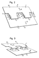
- Fig. 1 shows an elongated material web 1, in particular a metal sheet, in the meandering slots 2, 3 are cut.
- the slots 2, 3 can be introduced into the material web 1, for example by a punching or cutting process (eg rotary cutting process, laser cutting process) or another suitable process.
- the slots 2, 3 are each U-shaped, wherein the two legs 4, 5 run apart to the open side of the U out.
- the legs 4 as well as the legs 5 are connected to each other by linear base cuts 6, 7, which are each arranged parallel to each other.
- the U-shaped slots 2 are each at the same height, periodically consecutive along the longitudinal axis of the web 1 in a row.
- the U-shaped slots 3 along the longitudinal axis of the web 1 at regular intervals consecutively one behind the other, but the open sides of the U-shaped slots 2 and 3 to the other outer edge 8, 9 of the web 1 show.
- the U-shaped slots 2, 3 arranged so interlocking that the legs 4, 5 each overlap and between the legs 4, 5 webs 10, 11 are formed.
- the material web 1 has a surface 13 with a width 12 which extends from the outer edge 8 to the outer edge 9.
- Fig. 2 to 4 is for producing a metal element on the basis of the pattern after Fig. 1 used a folding process.
- the edge portions of the material web 1 are moved apart in opposite directions according to arrows 14, 15 that the webs 10, 11 are each bent at two bend lines 16, 17 and 18, 19.
- the two by the webs 10, 11 interconnected halves 20, 21 of the material web 1 move apart in a pivoting movement until they turn into the in Fig. 4 shown positions, where they are essentially back in the same plane.
- openings 22, 23 formed.
- the shape of the projections 24, 25 is, except for the web areas, complementary to the shape of the openings 22, 23rd
- the width 12 of the material web 1 has increased by twice the web length to the width 12 '. Essentially no stretching or bending stresses occur in the material of the material web 1 during the expansion or folding process. Only directly in the fold lines 16, 17, 18, 19 takes place by the refolding a bending of the material. The material expansion is negligible compared to the area enlargement.
- the material web 1 has a first edge region 26 adjoining the outer edge 8, a second edge region 27 adjoining the second outer edge 9, and a central region 28 lying between the two edge regions 26, 27, through which the two edge regions 26, 27 are joined together are connected.
- the middle region 28 comprises four sections 29, 30 shown in dashed lines, wherein each of these sections 29, 30 consists of three sections 31, 32, 33 and 34, 35, 36.
- each of these sections 29, 30 consists of three sections 31, 32, 33 and 34, 35, 36.
- the outer sections 31, 33 of the section 29 are hatched opposite obliquely to the middle section 32 lying therebetween.
- the outer portions 34 and 36 of the portions 30 are transversely hatched, while the intermediate central portion 35 is longitudinally hatched with respect to the longitudinal direction of the web 1.
- outer sections does not necessarily mean that these sections are closer to one of the outer edges 8, 9, as the middle sections, but that this term describes the division of the sections 29, 30 in three sections , wherein the "outer” sections are each the subsections which are interconnected by a common intermediate section lying between them .
- the material web 1 can be guided by a rolling device after completion of the folding process.
- the material which is triple-layered in the middle region 28 is compressed, at the same time resulting in work hardening of the material.
- the rolling process thus produces, on the one hand, a substantially flat surface 13 and, on the other hand, increased stability of the material web 1 also in the region of the crease lines 16, 17, 18, 19 and the relatively thin webs 10, 11, which form the middle sections 32, 35 form reached.
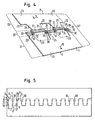
- FIGS Fig. 1 to 4 corresponds essentially to the Fig. 1 to 4 described embodiment, see that the same reference numerals as in FIGS Fig. 1 to 4 be used.
- the embodiment according to the Fig. 5 to 8 differs from the embodiment according to the Fig. 1 to 4 only in that between the U-shaped slots 2, 3 each have two more obliquely extending slots 37, 38 are provided. Because of these further slots 37, 38, two webs 10, 10 'and 11, 11', which are arranged one behind the other parallel to the direction of expansion according to the arrows 14, 15, are formed.
- the folding process is identical to that of the Fig. 2 to 4 described folding process.
- Advantageous to the embodiment according to the Fig. 5 to 8 is that an even higher stability of the expanded material web 1 is given by the additional webs 10 ', 11'.
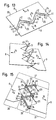
- Fig. 9 shows an embodiment in which instead of the U-shaped slots 2, 3 V-shaped slots 37, 38 are cut into the material web 1. Similar to the U-shaped slots 2, 3 and the V-shaped slots 37, 38 are each juxtaposed in the longitudinal direction of the web 1 and offset arranged interlocking.
- the V-shaped slots 37, 38 have legs 39, 40 which overlap one another, so that in each case webs 10, 11 are formed between the legs 39, 40.
- the material web 1 is in accordance with 10 to 12 in an identical way as already to the Fig. 2 to 4 described along two arrows 14, 15 moved apart, so that the width 12 of the web 1 after completion of the folding process to an enlarged width 12 'is expanded.
- the resulting width 12 'of the web 1 is identical in both cases, in which the Fig. 13 to 15 Only the number of creases 43, 44 are reduced.
- the material web 1 is fed to a smoothing device, with which the multilayer material sections are pressed together.
- the crease lines have been selected in an identical manner on both sides of the central region 28, it is in principle also possible, for example, the crease lines on one side of the central region 28 according to the embodiment of the 10 to 12 and on the other side of the central region 28 according to the embodiment according to FIGS Fig. 13 to 15 to choose.
- the flexural rigidity can also be increased by arranging successive sections 29, 30 along the length of the metal element not exclusively along a straight line, in particular in the longitudinal direction of the metal element, but rather that at least some sections 29, 30 are arranged laterally offset from one another. While in the embodiment according to Fig. 4 all sections 29, 30 follow one another in a straight line are in the embodiment according to Fig. 8 each lying closer to the outer edge 8 sections 29, 30 arranged laterally offset relative to the closer to the outer edge 9 lying portions 29, 30, so that the embodiment according to Fig. 8 has a greater flexural rigidity than that Fig. 4 , It would also be possible, for example, in the embodiment Fig. 4 to displace the sections 29 laterally relative to the sections 30 or to laterally displace a respective pair of sections 29, 30 relative to the next pair of sections 29, 30, thereby achieving increased flexural rigidity.
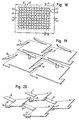
- Fig. 16 shows the pattern according to Fig. 9 , wherein instead of a single double row of V-shaped slots 37, 38, a plurality of such interlocking V-shaped slots are provided.
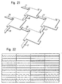
- Fig. 18 shows a pattern that allows expansion of the web 1 both along the arrows 14, 15 and at the same time along both arrows 45, 46 allows. With this pattern, a material expansion is thus possible not only along one axis, but along two mutually perpendicular axes.
- Fig. 22 Other possible patterns are in Fig. 22 shown.
- all pointed edges can also be replaced, for example, by corresponding curves.
- a multiple graduation as for example Fig. 5 in contrast to Fig. 1 shows, even with the patterns after Fig. 22 possible.
- FIGS. 23 and 24 two application examples of the invention shown.
- Fig. 23 schematically shows a corner profile 51, as used for example as a plaster profile.
- the corner profile 51 is formed as an L-shaped angle profile, wherein both legs of the angular corner profile 51 are provided with openings 22, 23 according to the invention. Through the openings 22, 23 it is ensured that the plaster used for plastering the corner profile 51 can pass through the corner profile 51 and thus a secure attachment of the corner profile 51 is ensured.
- Fig. 24 shows two uprights 52, which are each formed as C-shaped angle profiles. While the two legs 53, 54, to which, for example, a plate 55 is fastened with screws 56 are formed in the usual way as a solid material, the two base portions 57 of the stator profiles 52 are produced as inventively designed metal elements and provided with the corresponding openings 22, 23 , In this way it is ensured that the material consumption for the production of the stator profiles 53 is significantly reduced compared to conventional methods.
Claims (29)
- Elément métallique surfacique comportant une surface (13) qui s'étend depuis une première arête extérieure (8) jusqu'à une deuxième arête extérieure (9) qui est opposée à la première arête extérieure (8), la zone de l'élément métallique qui se raccorde à la première arête extérieure (8) forme une première zone de bord (26), et la zone de l'élément métallique qui se raccorde à la deuxième arête extérieure (9) forme une deuxième zone de bord (27), les deux zones de bord étant reliées entre elles par une zone médiane (28) située entre elles, et au moins dans une des zones de bord (26, 27) est réalisée au moins une percée (22, 23) totalement bordée, dont la bordure est formée d'une part par cette zone de bord (26, 27) et d'autre part par la zone médiane (28), la zone médiane (28) comprenant au moins deux tronçons (29, 30) qui sont constitués chacun par deux tronçons partiels (31, 33, 34, 36) situés à l'extérieur et par un tronçon partiel médian (32, 35) situé entre ceux-ci, les tronçons partiels (31, 33, 34, 36) situés à l'extérieur étant repliés par rapport au tronçon partiel médian (32, 35) pour produire la percée (22, 23), les tronçons (29, 30) formant une partie de la bordure de la percée (22, 23), et la zone médiane (28) y compris les tronçons (29, 30) étant réalisés d'un seul tenant avec les deux zones de bord (26, 27) de l'élément métallique,
caractérisé en ce que
dans la zone médiane (28) et pour chaque tronçon (29: 30) est réalisé au moins un autre tronçon (29, 30) similaire associé à ce tronçon (29 ; 30), les tronçons (29, 29 ; 30, 30) associés les uns aux autres étant agencés les uns derrière les autres dans une direction allant depuis la première zone de bord (26) jusqu'à la deuxième zone de bord (27), et chacun des deux tronçons partiels (31, 33 ; 34, 36) situés à l'extérieur, de l'un de ces tronçons (29, 30), est relié directement avec le tronçon partiel (31, 33 ; 34, 36) de l'autre tronçon (29, 30) correspondant situé à l'extérieur, par une zone surfacique (24, 25) de l'élément métallique. - Elément métallique selon la revendication 1,
caractérisé en ce que
au moins une partie des tronçons partiels (31, 33 ; 34, 36) situés à l'extérieur sont repliés en sens contraire les uns par rapport aux autres, c'est-à-dire dans des directions opposées l'une à l'autre. - Elément métallique selon la revendication 2,
caractérisé en ce que
au moins un des tronçons partiels (31, 34) situés à l'extérieur est replié vers la face supérieure du tronçon partiel médian (32, 35) et l'autre tronçon partiel (33, 36) situé à l'extérieur est replié vers la face inférieure du tronçon partiel médian (32, 35). - Elément métallique selon l'une quelconque des revendications précédentes,
caractérisé en ce que
au moins une partie des tronçons partiels situés à l'extérieur sont repliés dans le même sens les uns par rapport aux autres, c'est-à-dire orientés dans la même direction. - Elément métallique selon la revendication 4,
caractérisé en ce que
les deux tronçons partiels situés à l'extérieur sont repliés vers le même côté, c'est-à-dire les deux soit vers la face supérieure soit les deux vers la face inférieure du tronçon partiel médian. - Elément métallique selon l'une quelconque des revendications précédentes,
caractérisé en ce que
plusieurs percées (22, 23) sont réalisées dans au moins une des zones de bord (26, 27). - Elément métallique selon la revendication 6,
caractérisé en ce que
dans chacune des zones de bord (26, 27) sont réalisées plusieurs percées (22, 23). - Elément métallique selon l'une quelconque des revendications précédentes,
caractérisé en ce que
dans la région médiane (28) sont réalisées des percées additionnelles. - Elément métallique selon la revendication 8,
caractérisé en ce que
les percées réalisées dans la zone médiane (28) sont réalisées de manière correspondante aux percées (22, 23) réalisées dans les zones de bord (26, 27). - Elément métallique selon l'une quelconque des revendications précédentes,
caractérisé en ce que
un tronçon (29, 30) est réalisé sous forme de traverse (10, 10', 10", 11, 11', 11") avec des arêtes latérales s'étendant parallèlement les unes aux autres. - Elément métallique selon l'une quelconque des revendications précédentes,
caractérisé en ce que
les arêtes latérales de différentes traverses (10, 10', 10", 11, 11', 11") s'étendent parallèlement les unes aux autres ou en oblique les unes par rapport aux autres. - Elément métallique selon l'une quelconque des revendications précédentes,
caractérisé en ce que
la distance (12, 12') entre la première arête extérieure et la deuxième arête extérieure (8, 9) est nettement plus grande avec des tronçons partiels (31, 33, 34, 36) repliés qu'avec des tronçons partiels (31, 33, 34, 36) non repliés. - Elément métallique selon la revendication 12,
caractérisé en ce que
la distance (12') avec des tronçons partiels (31, 33, 34, 36) repliés est approximativement entre 1,3 et 4 fois, en particulier approximativement entre 2 et 3 fois plus grande que la distance (12) avec des tronçons partiels (31, 33, 34, 36) non repliés. - Elément métallique selon l'une quelconque des revendications précédentes,
caractérisé en ce que
les percées (22, 23) se répètent à des distances régulières. - Elément métallique selon l'une quelconque des revendications précédentes,
caractérisé en ce que
le matériau de l'élément métallique est sensiblement non allongé, c'est-à-dire qu'il ne se produit pas d'étirage du matériau pour générer la percée. - Elément métallique selon l'une quelconque des revendications précédentes,
caractérisé en ce que
les zones de bord (26, 27), à l'exception des percées (22, 23), possèdent une surface (13) sensiblement plane. - Elément métallique selon l'une quelconque des revendications précédentes,
caractérisé en ce que
la surface (13) de l'élément métallique, à l'exception des percées (22, 23), est réalisée sensiblement plane. - Elément métallique selon l'une quelconque des revendications précédentes,
caractérisé en ce que
les tronçons partiels (31, 33, 34, 36) repliés situés à l'extérieur, forment avec le tronçon partiel médian (32, 35) respectif un angle d'environ 110° à 0°, de préférence d'environ 90° à 0°, avantageusement d'environ 45° à 0°, en particulier d'environ 10° à 0°. - Elément métallique selon l'une quelconque des revendications précédentes,
caractérisé en ce que
chacun des tronçons partiels (31, 33, 34, 36) repliés situés à l'extérieur, qui est relié directement avec une zone de bord (26, 27), passe de façon continue, en particulier de façon plane dans la zone de bord (26, 27) qui lui est reliée. - Elément métallique selon l'une quelconque des revendications précédentes,
caractérisé en ce que
à la première et/ou à la deuxième arête extérieure (8, 9) se raccorde un autre tronçon métallique (53, 54) respectif qui forme un profil angulaire (51, 52) conjointement avec le matériau s'étendant entre la première et la deuxième arête extérieure (8, 9). - Elément métallique selon la revendication 20,
caractérisé en ce que
le profil angulaire (51, 52) est réalisé en forme de L, en forme de V, en forme de U, en forme de C, en forme de T, en forme de I ou en forme de Z. - Elément métallique selon l'une des revendications 20 ou 21,
caractérisé en ce que
l'autre tronçon métallique (53, 54) ou les autres tronçons métalliques sont réalisés d'un seul tenant avec la partie restante de l'élément métallique. - Elément métallique selon l'une quelconque des revendications précédentes,
caractérisé en ce que
il y a additionnellement à la première et à la deuxième zone de bord (26, 27) une troisième et une quatrième zone de bord qui sont opposées l'une à l'autre et qui s'étendent chacune transversalement, en particulier perpendiculairement à la première et à la deuxième zone de bord (26, 27), et en ce que la réalisation de la surface (13) dans une direction depuis la troisième vers la quatrième zone de bord correspond sensiblement à la réalisation de la surface (13) dans une direction depuis la première vers la deuxième zone de bord (26, 27). - Elément métallique selon l'une quelconque des revendications précédentes,
caractérisé en ce que
pour augmenter la rigidité à la flexion sur la longueur de l'élément métallique, des tronçons successifs (29, 30) ne sont pas agencés exclusivement le long d'une ligne droite, en particulier en direction longitudinale de l'élément métallique, mais en ce qu'au moins certains tronçons (29, 30) sont agencés en décalage latéral les uns par rapport aux autres. - Utilisation d'un élément métallique selon l'une quelconque des revendications précédentes en tant qu'élément de profil (51, 52), en particulier en tant que profils de coin ou de montant, en tant que grille de protection, en tant que tronçon de clôture, en tant que natte filtrante, en tant qu'élément de protection sonore, en tant qu'espalier, en tant qu'élément de marchepied, en tant que natte d'armature, en tant qu'insert dans des matériaux composites, en tant que canal à câbles, en tant que bande perforée, en tant qu'élément de montage ou en tant que profil décoratif.
- Procédé de fabrication d'un élément métallique présentant les caractéristiques d'une des revendications 1 à 24, dans lequel pour produire les tronçons (29, 30), une bande de matériau (1) est pourvue de découpes (2, 3, 37, 38) selon un patron prédéterminé, et pour produire une percée (22, 23), les tronçons partiels (31, 33, 34, 36) sont chacun repliés par rapport au tronçon partiel médian (32, 35),
caractérisé en ce que
pour replier les tronçons partiels (31, 33, 34, 36) situés à l'extérieur, par rapport au tronçon partiel médian (32, 35), les zones de bord (26, 27) de l'élément métallique sont écartées l'une de l'autre dans un mouvement de pivotement dans des directions (14, 15) opposées jusqu'à ce qu'elles se trouvent sensiblement dans le même plan après pivotement total. - Procédé selon la revendication 26,
caractérisé en ce que
les découpes (2, 3, 37, 38) dans la bande de matériau (1) sont produites par un procédé de coupe par rotation ou par un procédé de coupe au laser. - Procédé selon la revendication 26 ou 27,
caractérisé en ce que
après le repliage, l'élément métallique est guidé à travers un laminoir. - Procédé selon la revendication 28,
caractérisé en ce que
un écrouissage de la bande de matériau, en particulier dans la zone médiane (28), a lieu à travers le laminoir.
Priority Applications (3)
| Application Number | Priority Date | Filing Date | Title |
|---|---|---|---|
| EP06017468A EP1724409B1 (fr) | 2002-12-18 | 2003-11-25 | Élément métallique plat et élément profilé |
| SI200331480T SI1573144T1 (sl) | 2002-12-18 | 2003-11-25 | Ploskovni kovinski element in profilni element |
| CY20081101417T CY1108627T1 (el) | 2002-12-18 | 2008-12-08 | Επιπεδο μεταλλικο στοιχειο και στοιχειο προφιλ |
Applications Claiming Priority (3)
| Application Number | Priority Date | Filing Date | Title |
|---|---|---|---|
| DE10259307 | 2002-12-18 | ||
| DE10259307A DE10259307A1 (de) | 2002-12-18 | 2002-12-18 | Flächiges Metallelement und Profilelement |
| PCT/EP2003/013249 WO2004055289A1 (fr) | 2002-12-18 | 2003-11-25 | Element metallique plat et element profile |
Related Child Applications (1)
| Application Number | Title | Priority Date | Filing Date |
|---|---|---|---|
| EP06017468A Division EP1724409B1 (fr) | 2002-12-18 | 2003-11-25 | Élément métallique plat et élément profilé |
Publications (2)
| Publication Number | Publication Date |
|---|---|
| EP1573144A1 EP1573144A1 (fr) | 2005-09-14 |
| EP1573144B1 true EP1573144B1 (fr) | 2008-09-24 |
Family
ID=32477763
Family Applications (2)
| Application Number | Title | Priority Date | Filing Date |
|---|---|---|---|
| EP06017468A Expired - Lifetime EP1724409B1 (fr) | 2002-12-18 | 2003-11-25 | Élément métallique plat et élément profilé |
| EP03767654A Expired - Lifetime EP1573144B1 (fr) | 2002-12-18 | 2003-11-25 | Element metallique plat et element profile |
Family Applications Before (1)
| Application Number | Title | Priority Date | Filing Date |
|---|---|---|---|
| EP06017468A Expired - Lifetime EP1724409B1 (fr) | 2002-12-18 | 2003-11-25 | Élément métallique plat et élément profilé |
Country Status (26)
| Country | Link |
|---|---|
| US (1) | US7820302B2 (fr) |
| EP (2) | EP1724409B1 (fr) |
| AR (1) | AR042502A1 (fr) |
| AT (2) | ATE409258T1 (fr) |
| AU (1) | AU2003292114C1 (fr) |
| BR (2) | BR122013027113B1 (fr) |
| CA (1) | CA2510755C (fr) |
| CY (2) | CY1108622T1 (fr) |
| DE (3) | DE10259307A1 (fr) |
| DK (2) | DK1573144T3 (fr) |
| ES (2) | ES2314253T3 (fr) |
| HR (2) | HRP20050561B1 (fr) |
| IL (2) | IL168923A (fr) |
| ME (1) | MEP54908A (fr) |
| MX (1) | MXPA05006705A (fr) |
| MY (1) | MY138545A (fr) |
| NZ (1) | NZ540654A (fr) |
| PL (2) | PL215863B1 (fr) |
| PT (2) | PT1724409E (fr) |
| RS (3) | RS51503B (fr) |
| RU (1) | RU2303685C2 (fr) |
| SI (2) | SI1724409T1 (fr) |
| TW (1) | TWI324205B (fr) |
| UA (1) | UA81645C2 (fr) |
| WO (1) | WO2004055289A1 (fr) |
| ZA (2) | ZA200404654B (fr) |
Families Citing this family (18)
| Publication number | Priority date | Publication date | Assignee | Title |
|---|---|---|---|---|
| AR054817A1 (es) * | 2005-09-01 | 2007-07-18 | Rojas Ubilla Jose | Perfil con seccion desplegable |
| DE102006010795A1 (de) | 2006-03-08 | 2007-09-13 | Protektorwerk Florenz Maisch Gmbh & Co. Kg | Vorrichtung zum Aufweiten von Metallelementen |
| DE102007053471A1 (de) | 2007-11-09 | 2009-05-14 | Protektorwerk Florenz Maisch Gmbh & Co. Kg | Metallprofil |
| EP2148039A1 (fr) * | 2008-07-22 | 2010-01-27 | Trenzametal, S.L. | Panneau de construction en trois dimensions et un seul morceau |
| DE102009038051A1 (de) | 2009-08-19 | 2011-02-24 | Volkswagen Ag | Kupplungspedalanordnung |
| DE102009038876A1 (de) | 2009-08-26 | 2011-03-03 | Protektorwerk Florenz Maisch Gmbh & Co. Kg | Profilelement und Verfahren zum Herstellen eines Profilelements |
| ES2529422T3 (es) | 2009-10-01 | 2015-02-19 | Protektorwerk Florenz Maisch Gmbh & Co. Kg | Elemento perfilado de construcción ligera conformado en frío de pared delgada y procedimiento para la producción de un elemento perfilado de este tipo |
| DE102009048152A1 (de) * | 2009-10-01 | 2011-04-07 | Protektorwerk Florenz Maisch Gmbh & Co. Kg | Dünnwandig kaltverformtes Profilelement und Verfahren zum Herstellen eines solchen Profilelements |
| DE102013200519A1 (de) | 2013-01-15 | 2014-07-17 | Protektorwerk Florenz Maisch Gmbh & Co Kg | Bauprofilelement |
| EP2792630A1 (fr) * | 2013-04-16 | 2014-10-22 | Kone Corporation | Cabine d'ascenseur et ascenseur |
| US9708816B2 (en) | 2014-05-30 | 2017-07-18 | Sacks Industrial Corporation | Stucco lath and method of manufacture |
| US9752323B2 (en) | 2015-07-29 | 2017-09-05 | Sacks Industrial Corporation | Light-weight metal stud and method of manufacture |
| AU2016273959B2 (en) * | 2015-12-21 | 2021-10-21 | Autex Industries Limited | Expanding Panel and Method of Manufacture |
| US9797142B1 (en) | 2016-09-09 | 2017-10-24 | Sacks Industrial Corporation | Lath device, assembly and method |
| DE102017100920A1 (de) * | 2017-01-18 | 2018-07-19 | Protektorwerk Florenz Maisch Gmbh & Co. Kg | Verfahren und Vorrichtung zum Aufweiten eines Metallelements |
| US10760266B2 (en) | 2017-08-14 | 2020-09-01 | Clarkwestern Dietrich Building Systems Llc | Varied length metal studs |
| US11351593B2 (en) | 2018-09-14 | 2022-06-07 | Structa Wire Ulc | Expanded metal formed using rotary blades and rotary blades to form such |
| DE102020109118B3 (de) * | 2020-04-01 | 2021-03-25 | Matrix Module Gmbh | Abstandsstruktur, Sandwich-Konstruktion mit einer solchen Abstandsstruktur und Verfahren zur Herstellung einer solchen Abstandsstruktur |
Family Cites Families (13)
| Publication number | Priority date | Publication date | Assignee | Title |
|---|---|---|---|---|
| US438327A (en) * | 1890-10-14 | Metallic lathing | ||
| US181850A (en) * | 1876-09-05 | Improvement in metallic lathings | ||
| US1113195A (en) * | 1908-07-01 | 1914-10-13 | Norris Elmore Clark | Reticulated metal fabric. |
| US3008551A (en) * | 1958-05-29 | 1961-11-14 | Dana Corp | Structural panel construction |
| US3111204A (en) * | 1959-08-24 | 1963-11-19 | British Uralite Ltd | Structural element and a method of making a structural element |
| US3287873A (en) * | 1964-01-20 | 1966-11-29 | Mcdaill Laura | Light regulating panel screen |
| FR2518611B1 (fr) * | 1981-12-17 | 1985-08-23 | Kieffer Joseph | Panneau prefabrique pour constructions immobilieres |
| EP0097659B1 (fr) | 1981-12-17 | 1987-05-06 | Joseph André KIEFFER | Structure tridimensionelle monolithique en metal deploye applicable notamment comme armature d'un panneau de construction immobiliere |
| US4545170A (en) * | 1983-12-21 | 1985-10-08 | Donn Incorporated | Expanded metal products |
| WO1986006431A1 (fr) * | 1985-05-02 | 1986-11-06 | Donn Incorporated | Produit en metal deploye |
| ZA895832B (en) | 1988-09-29 | 1990-04-25 | Gospel Resource Ltd | Sheet metal article |
| NZ231531A (en) | 1989-11-27 | 1992-08-26 | Gospel Resource Ltd | Sheet metal article made by slitting and expanding |
| US5081814A (en) * | 1990-10-22 | 1992-01-21 | Alabama Metal Industries | Lath panel and method of manufacture |
-
2002
- 2002-12-18 DE DE10259307A patent/DE10259307A1/de not_active Withdrawn
-
2003
- 2003-11-25 CA CA002510755A patent/CA2510755C/fr not_active Expired - Lifetime
- 2003-11-25 NZ NZ540654A patent/NZ540654A/en not_active IP Right Cessation
- 2003-11-25 UA UAA200505913A patent/UA81645C2/uk unknown
- 2003-11-25 PT PT06017468T patent/PT1724409E/pt unknown
- 2003-11-25 AU AU2003292114A patent/AU2003292114C1/en not_active Ceased
- 2003-11-25 ES ES03767654T patent/ES2314253T3/es not_active Expired - Lifetime
- 2003-11-25 MX MXPA05006705A patent/MXPA05006705A/es active IP Right Grant
- 2003-11-25 RS YUP-2005/0485A patent/RS51503B/en unknown
- 2003-11-25 AT AT03767654T patent/ATE409258T1/de active
- 2003-11-25 SI SI200331459T patent/SI1724409T1/sl unknown
- 2003-11-25 PL PL375846A patent/PL215863B1/pl unknown
- 2003-11-25 WO PCT/EP2003/013249 patent/WO2004055289A1/fr active Application Filing
- 2003-11-25 SI SI200331480T patent/SI1573144T1/sl unknown
- 2003-11-25 RU RU2005122472/03A patent/RU2303685C2/ru not_active IP Right Cessation
- 2003-11-25 RS RS20100507A patent/RS51803B/en unknown
- 2003-11-25 RS RSP-2010/0507A patent/RS20100507A/en unknown
- 2003-11-25 BR BR122013027113-9A patent/BR122013027113B1/pt not_active IP Right Cessation
- 2003-11-25 DK DK03767654T patent/DK1573144T3/da active
- 2003-11-25 DE DE50310554T patent/DE50310554D1/de not_active Expired - Lifetime
- 2003-11-25 AT AT06017468T patent/ATE407270T1/de active
- 2003-11-25 ME MEP-549/08A patent/MEP54908A/xx unknown
- 2003-11-25 PL PL401031A patent/PL217245B1/pl unknown
- 2003-11-25 DK DK06017468T patent/DK1724409T3/da active
- 2003-11-25 ES ES06017468T patent/ES2314799T3/es not_active Expired - Lifetime
- 2003-11-25 US US10/538,381 patent/US7820302B2/en active Active
- 2003-11-25 EP EP06017468A patent/EP1724409B1/fr not_active Expired - Lifetime
- 2003-11-25 BR BRPI0317562-6A patent/BR0317562B1/pt active IP Right Grant
- 2003-11-25 EP EP03767654A patent/EP1573144B1/fr not_active Expired - Lifetime
- 2003-11-25 PT PT03767654T patent/PT1573144E/pt unknown
- 2003-11-25 DE DE50310453T patent/DE50310453D1/de not_active Expired - Lifetime
- 2003-12-03 TW TW092133984A patent/TWI324205B/zh not_active IP Right Cessation
- 2003-12-12 MY MYPI20034782A patent/MY138545A/en unknown
- 2003-12-17 AR ARP030104674A patent/AR042502A1/es active IP Right Grant
-
2005
- 2005-05-07 ZA ZA200404654A patent/ZA200404654B/xx unknown
- 2005-06-01 IL IL168923A patent/IL168923A/en active IP Right Grant
- 2005-06-07 ZA ZA2005/04654A patent/ZA200504654B/en unknown
- 2005-06-16 HR HRP20050561AA patent/HRP20050561B1/xx not_active IP Right Cessation
-
2007
- 2007-12-03 IL IL187854A patent/IL187854A/en active IP Right Grant
-
2008
- 2008-12-02 CY CY20081101385T patent/CY1108622T1/el unknown
- 2008-12-08 CY CY20081101417T patent/CY1108627T1/el unknown
-
2009
- 2009-07-15 HR HRP20090399AA patent/HRP20090399B1/hr not_active IP Right Cessation
Also Published As
Similar Documents
| Publication | Publication Date | Title |
|---|---|---|
| EP1573144B1 (fr) | Element metallique plat et element profile | |
| EP1631728B1 (fr) | Rail profile et procede de realisation d'un rail profile | |
| EP1074671B1 (fr) | Poteau profilé configuré en tant que profilé pour cloison légère | |
| EP2483492B1 (fr) | Élément profilé de construction léger, à parois minces, formé à froid, et procédé de fabrication d'un tel élément profilé | |
| DE3936213A1 (de) | Verfahren zur herstellung einer teleskopabdeckung | |
| EP2729264B1 (fr) | Profilé de construction ainsi que procédé et dispositif pour fabriquer un tel profilé de construction | |
| EP1869278B1 (fr) | Profilé composite et méthode de fabrication de profilé composite pour cadres d'éléments de paroi, portes et fenêtres | |
| EP3730718B1 (fr) | Dispositif de façade | |
| EP0203385A2 (fr) | Plaque profilée trapézoidale | |
| DE19605079C1 (de) | Schalungselement | |
| EP3184236B1 (fr) | Panneau extensible | |
| EP2047922A1 (fr) | Elément en tôle, en particulier demi-produit, destiné au montage de véhicules sur rail et procédé de montage d'un élément de surface à partir de celui-ci | |
| DE102007053473A1 (de) | Metallelement | |
| EP0565129B1 (fr) | Fabrication d'un panneau de porte | |
| EP2628554B1 (fr) | Procédé de modification de la largeur d'une bande de tôle | |
| DE102012014790A1 (de) | Montageschiene sowie Verfahren zu deren Herstellung | |
| DE102009033437B4 (de) | Sonnenschutzrollo | |
| EP3551819A2 (fr) | Outil de chantier, en particulier rabot à grille et méthode de fabrication dudit outil | |
| DE10147645A1 (de) | Schallabschirmelement und Verfahren zur Herstellung | |
| EP1160026A2 (fr) | Procédé de production de métal déployé ainsi que le métal déployé produit par ce procédé | |
| DE102021002669A1 (de) | Hygienewand | |
| DE102020126860A1 (de) | Konsole für Fassadenelemente und Verfahren zu dessen Herstellung | |
| DE102006052558A1 (de) | Deckenelement für eine Heiz-/Kühldecke sowie Heiz-/Kühldecke mit mindestens einem derartigen Deckenelement | |
| DE202012104960U1 (de) | Abdeckung, insbesondere für ein Instrumenttafelbauteil eines Kraftfahrzeugs | |
| WO2013014044A1 (fr) | Procédé de fabrication d'un rail profilé |
Legal Events
| Date | Code | Title | Description |
|---|---|---|---|
| PUAI | Public reference made under article 153(3) epc to a published international application that has entered the european phase |
Free format text: ORIGINAL CODE: 0009012 |
|
| 17P | Request for examination filed |
Effective date: 20050530 |
|
| AK | Designated contracting states |
Kind code of ref document: A1 Designated state(s): AT BE BG CH CY CZ DE DK EE ES FI FR GB GR HU IE IT LI LU MC NL PT RO SE SI SK TR |
|
| AX | Request for extension of the european patent |
Extension state: AL LT LV MK |
|
| RAX | Requested extension states of the european patent have changed |
Extension state: MK Payment date: 20050530 Extension state: LV Payment date: 20050530 Extension state: LT Payment date: 20050530 |
|
| GRAP | Despatch of communication of intention to grant a patent |
Free format text: ORIGINAL CODE: EPIDOSNIGR1 |
|
| GRAS | Grant fee paid |
Free format text: ORIGINAL CODE: EPIDOSNIGR3 |
|
| GRAA | (expected) grant |
Free format text: ORIGINAL CODE: 0009210 |
|
| AK | Designated contracting states |
Kind code of ref document: B1 Designated state(s): AT BE BG CH CY CZ DE DK EE ES FI FR GB GR HU IE IT LI LU MC NL PT RO SE SI SK TR |
|
| AX | Request for extension of the european patent |
Extension state: LT LV MK |
|
| REG | Reference to a national code |
Ref country code: GB Ref legal event code: FG4D Free format text: NOT ENGLISH |
|
| REG | Reference to a national code |
Ref country code: CH Ref legal event code: EP |
|
| REG | Reference to a national code |
Ref country code: CH Ref legal event code: NV Representative=s name: DR. GRAF & PARTNER INTELLECTUAL PROPERTY |
|
| REG | Reference to a national code |
Ref country code: IE Ref legal event code: FG4D Free format text: LANGUAGE OF EP DOCUMENT: GERMAN |
|
| REF | Corresponds to: |
Ref document number: 50310554 Country of ref document: DE Date of ref document: 20081106 Kind code of ref document: P |
|
| REG | Reference to a national code |
Ref country code: PT Ref legal event code: SC4A Free format text: AVAILABILITY OF NATIONAL TRANSLATION Effective date: 20081106 |
|
| REG | Reference to a national code |
Ref country code: SE Ref legal event code: TRGR |
|
| REG | Reference to a national code |
Ref country code: GR Ref legal event code: EP Ref document number: 20080403181 Country of ref document: GR |
|
| REG | Reference to a national code |
Ref country code: RO Ref legal event code: EPE |
|
| REG | Reference to a national code |
Ref country code: DK Ref legal event code: T3 |
|
| REG | Reference to a national code |
Ref country code: ES Ref legal event code: FG2A Ref document number: 2314253 Country of ref document: ES Kind code of ref document: T3 |
|
| PLBE | No opposition filed within time limit |
Free format text: ORIGINAL CODE: 0009261 |
|
| STAA | Information on the status of an ep patent application or granted ep patent |
Free format text: STATUS: NO OPPOSITION FILED WITHIN TIME LIMIT |
|
| 26N | No opposition filed |
Effective date: 20090625 |
|
| REG | Reference to a national code |
Ref country code: CH Ref legal event code: PFA Owner name: PROTEKTORWERK FLORENZ MAISCH GMBH & CO. KG Free format text: PROTEKTORWERK FLORENZ MAISCH GMBH & CO. KG#VIKTORIASTRASSE 58#76571 GAGGENAU (DE) -TRANSFER TO- PROTEKTORWERK FLORENZ MAISCH GMBH & CO. KG#VIKTORIASTRASSE 58#76571 GAGGENAU (DE) |
|
| REG | Reference to a national code |
Ref country code: EE Ref legal event code: HC1A Ref document number: E002780 Country of ref document: EE |
|
| PGFP | Annual fee paid to national office [announced via postgrant information from national office to epo] |
Ref country code: EE Payment date: 20131113 Year of fee payment: 11 Ref country code: MC Payment date: 20131115 Year of fee payment: 11 |
|
| PGFP | Annual fee paid to national office [announced via postgrant information from national office to epo] |
Ref country code: HU Payment date: 20131120 Year of fee payment: 11 Ref country code: SI Payment date: 20131030 Year of fee payment: 11 |
|
| PGFP | Annual fee paid to national office [announced via postgrant information from national office to epo] |
Ref country code: CY Payment date: 20131113 Year of fee payment: 11 |
|
| PGFP | Annual fee paid to national office [announced via postgrant information from national office to epo] |
Ref country code: FI Payment date: 20141112 Year of fee payment: 12 Ref country code: SK Payment date: 20141124 Year of fee payment: 12 Ref country code: SE Payment date: 20141119 Year of fee payment: 12 |
|
| PG25 | Lapsed in a contracting state [announced via postgrant information from national office to epo] |
Ref country code: MC Free format text: LAPSE BECAUSE OF NON-PAYMENT OF DUE FEES Effective date: 20141201 |
|
| REG | Reference to a national code |
Ref country code: EE Ref legal event code: MM4A Ref document number: E002780 Country of ref document: EE Effective date: 20141130 |
|
| REG | Reference to a national code |
Ref country code: LT Ref legal event code: MM9D Effective date: 20141125 |
|
| PG25 | Lapsed in a contracting state [announced via postgrant information from national office to epo] |
Ref country code: EE Free format text: LAPSE BECAUSE OF NON-PAYMENT OF DUE FEES Effective date: 20141130 Ref country code: CY Free format text: LAPSE BECAUSE OF NON-PAYMENT OF DUE FEES Effective date: 20141125 Ref country code: SI Free format text: LAPSE BECAUSE OF NON-PAYMENT OF DUE FEES Effective date: 20141126 |
|
| PG25 | Lapsed in a contracting state [announced via postgrant information from national office to epo] |
Ref country code: HU Free format text: LAPSE BECAUSE OF NON-PAYMENT OF DUE FEES Effective date: 20141126 |
|
| REG | Reference to a national code |
Ref country code: SI Ref legal event code: KO00 Effective date: 20150717 |
|
| REG | Reference to a national code |
Ref country code: FR Ref legal event code: PLFP Year of fee payment: 13 |
|
| REG | Reference to a national code |
Ref country code: SK Ref legal event code: MM4A Ref document number: E 4763 Country of ref document: SK Effective date: 20151125 |
|
| PG25 | Lapsed in a contracting state [announced via postgrant information from national office to epo] |
Ref country code: SE Free format text: LAPSE BECAUSE OF NON-PAYMENT OF DUE FEES Effective date: 20151126 Ref country code: SK Free format text: LAPSE BECAUSE OF NON-PAYMENT OF DUE FEES Effective date: 20151125 |
|
| REG | Reference to a national code |
Ref country code: FR Ref legal event code: PLFP Year of fee payment: 14 |
|
| PG25 | Lapsed in a contracting state [announced via postgrant information from national office to epo] |
Ref country code: FI Free format text: LAPSE BECAUSE OF NON-PAYMENT OF DUE FEES Effective date: 20151125 |
|
| REG | Reference to a national code |
Ref country code: FR Ref legal event code: PLFP Year of fee payment: 15 |
|
| PGFP | Annual fee paid to national office [announced via postgrant information from national office to epo] |
Ref country code: LU Payment date: 20171120 Year of fee payment: 15 |
|
| PGFP | Annual fee paid to national office [announced via postgrant information from national office to epo] |
Ref country code: CZ Payment date: 20171122 Year of fee payment: 15 |
|
| PGFP | Annual fee paid to national office [announced via postgrant information from national office to epo] |
Ref country code: BG Payment date: 20171122 Year of fee payment: 15 Ref country code: IE Payment date: 20171121 Year of fee payment: 15 |
|
| PGFP | Annual fee paid to national office [announced via postgrant information from national office to epo] |
Ref country code: NL Payment date: 20181120 Year of fee payment: 16 |
|
| PGFP | Annual fee paid to national office [announced via postgrant information from national office to epo] |
Ref country code: PT Payment date: 20181120 Year of fee payment: 16 Ref country code: RO Payment date: 20181030 Year of fee payment: 16 |
|
| PGFP | Annual fee paid to national office [announced via postgrant information from national office to epo] |
Ref country code: PL Payment date: 20190122 Year of fee payment: 11 |
|
| PG25 | Lapsed in a contracting state [announced via postgrant information from national office to epo] |
Ref country code: LU Free format text: LAPSE BECAUSE OF NON-PAYMENT OF DUE FEES Effective date: 20181125 Ref country code: CZ Free format text: LAPSE BECAUSE OF NON-PAYMENT OF DUE FEES Effective date: 20181125 |
|
| REG | Reference to a national code |
Ref country code: IE Ref legal event code: MM4A |
|
| PG25 | Lapsed in a contracting state [announced via postgrant information from national office to epo] |
Ref country code: BG Free format text: LAPSE BECAUSE OF NON-PAYMENT OF DUE FEES Effective date: 20190531 |
|
| PG25 | Lapsed in a contracting state [announced via postgrant information from national office to epo] |
Ref country code: IE Free format text: LAPSE BECAUSE OF NON-PAYMENT OF DUE FEES Effective date: 20181125 |
|
| PGFP | Annual fee paid to national office [announced via postgrant information from national office to epo] |
Ref country code: DK Payment date: 20191122 Year of fee payment: 17 Ref country code: IT Payment date: 20191128 Year of fee payment: 17 Ref country code: BE Payment date: 20191120 Year of fee payment: 17 |
|
| PGFP | Annual fee paid to national office [announced via postgrant information from national office to epo] |
Ref country code: AT Payment date: 20191121 Year of fee payment: 17 |
|
| REG | Reference to a national code |
Ref country code: NL Ref legal event code: MM Effective date: 20191201 |
|
| PG25 | Lapsed in a contracting state [announced via postgrant information from national office to epo] |
Ref country code: PT Free format text: LAPSE BECAUSE OF NON-PAYMENT OF DUE FEES Effective date: 20200626 Ref country code: GR Free format text: LAPSE BECAUSE OF NON-PAYMENT OF DUE FEES Effective date: 20200609 Ref country code: RO Free format text: LAPSE BECAUSE OF NON-PAYMENT OF DUE FEES Effective date: 20191125 |
|
| PG25 | Lapsed in a contracting state [announced via postgrant information from national office to epo] |
Ref country code: NL Free format text: LAPSE BECAUSE OF NON-PAYMENT OF DUE FEES Effective date: 20191201 |
|
| PGFP | Annual fee paid to national office [announced via postgrant information from national office to epo] |
Ref country code: CH Payment date: 20201118 Year of fee payment: 18 |
|
| PGFP | Annual fee paid to national office [announced via postgrant information from national office to epo] |
Ref country code: ES Payment date: 20210122 Year of fee payment: 18 |
|
| REG | Reference to a national code |
Ref country code: DK Ref legal event code: EBP Effective date: 20201130 |
|
| REG | Reference to a national code |
Ref country code: AT Ref legal event code: MM01 Ref document number: 409258 Country of ref document: AT Kind code of ref document: T Effective date: 20201125 |
|
| REG | Reference to a national code |
Ref country code: BE Ref legal event code: MM Effective date: 20201130 |
|
| PG25 | Lapsed in a contracting state [announced via postgrant information from national office to epo] |
Ref country code: AT Free format text: LAPSE BECAUSE OF NON-PAYMENT OF DUE FEES Effective date: 20201125 |
|
| PG25 | Lapsed in a contracting state [announced via postgrant information from national office to epo] |
Ref country code: IT Free format text: LAPSE BECAUSE OF NON-PAYMENT OF DUE FEES Effective date: 20201125 |
|
| PG25 | Lapsed in a contracting state [announced via postgrant information from national office to epo] |
Ref country code: DK Free format text: LAPSE BECAUSE OF NON-PAYMENT OF DUE FEES Effective date: 20201130 |
|
| PGFP | Annual fee paid to national office [announced via postgrant information from national office to epo] |
Ref country code: GB Payment date: 20211119 Year of fee payment: 19 Ref country code: FR Payment date: 20211122 Year of fee payment: 19 |
|
| PG25 | Lapsed in a contracting state [announced via postgrant information from national office to epo] |
Ref country code: TR Free format text: LAPSE BECAUSE OF NON-PAYMENT OF DUE FEES Effective date: 20191125 |
|
| REG | Reference to a national code |
Ref country code: CH Ref legal event code: PL |
|
| PG25 | Lapsed in a contracting state [announced via postgrant information from national office to epo] |
Ref country code: BE Free format text: LAPSE BECAUSE OF NON-PAYMENT OF DUE FEES Effective date: 20201130 |
|
| REG | Reference to a national code |
Ref country code: ES Ref legal event code: FD2A Effective date: 20230210 |
|
| PG25 | Lapsed in a contracting state [announced via postgrant information from national office to epo] |
Ref country code: ES Free format text: LAPSE BECAUSE OF NON-PAYMENT OF DUE FEES Effective date: 20211126 |
|
| P01 | Opt-out of the competence of the unified patent court (upc) registered |
Effective date: 20230526 |
|
| GBPC | Gb: european patent ceased through non-payment of renewal fee |
Effective date: 20221125 |
|
| PG25 | Lapsed in a contracting state [announced via postgrant information from national office to epo] |
Ref country code: LI Free format text: LAPSE BECAUSE OF NON-PAYMENT OF DUE FEES Effective date: 20220630 Ref country code: CH Free format text: LAPSE BECAUSE OF NON-PAYMENT OF DUE FEES Effective date: 20220630 |
|
| PGFP | Annual fee paid to national office [announced via postgrant information from national office to epo] |
Ref country code: DE Payment date: 20230405 Year of fee payment: 20 |
|
| PG25 | Lapsed in a contracting state [announced via postgrant information from national office to epo] |
Ref country code: GB Free format text: LAPSE BECAUSE OF NON-PAYMENT OF DUE FEES Effective date: 20221125 |
|
| REG | Reference to a national code |
Ref country code: DE Ref legal event code: R071 Ref document number: 50310554 Country of ref document: DE |
|
| PG25 | Lapsed in a contracting state [announced via postgrant information from national office to epo] |
Ref country code: FR Free format text: LAPSE BECAUSE OF NON-PAYMENT OF DUE FEES Effective date: 20221130 |