EP1573144B1 - Planar metal element and profile element - Google Patents
Planar metal element and profile element Download PDFInfo
- Publication number
- EP1573144B1 EP1573144B1 EP03767654A EP03767654A EP1573144B1 EP 1573144 B1 EP1573144 B1 EP 1573144B1 EP 03767654 A EP03767654 A EP 03767654A EP 03767654 A EP03767654 A EP 03767654A EP 1573144 B1 EP1573144 B1 EP 1573144B1
- Authority
- EP
- European Patent Office
- Prior art keywords
- metal element
- accordance
- sections
- section
- region
- Prior art date
- Legal status (The legal status is an assumption and is not a legal conclusion. Google has not performed a legal analysis and makes no representation as to the accuracy of the status listed.)
- Expired - Lifetime
Links
- 229910052751 metal Inorganic materials 0.000 title claims description 105
- 239000002184 metal Substances 0.000 title claims description 102
- 239000000463 material Substances 0.000 claims description 57
- 238000000034 method Methods 0.000 claims description 27
- 238000004519 manufacturing process Methods 0.000 claims description 17
- 238000005452 bending Methods 0.000 claims description 6
- 238000005520 cutting process Methods 0.000 claims description 5
- 238000005482 strain hardening Methods 0.000 claims description 4
- 239000002131 composite material Substances 0.000 claims description 3
- 238000003698 laser cutting Methods 0.000 claims description 2
- 230000001681 protective effect Effects 0.000 claims description 2
- 230000009194 climbing Effects 0.000 claims 1
- 230000002787 reinforcement Effects 0.000 claims 1
- 210000002414 leg Anatomy 0.000 description 17
- 239000011505 plaster Substances 0.000 description 6
- 238000005096 rolling process Methods 0.000 description 4
- 230000015572 biosynthetic process Effects 0.000 description 3
- 238000004080 punching Methods 0.000 description 3
- 238000013459 approach Methods 0.000 description 2
- 239000007858 starting material Substances 0.000 description 2
- 239000002699 waste material Substances 0.000 description 2
- 229910001335 Galvanized steel Inorganic materials 0.000 description 1
- HCHKCACWOHOZIP-UHFFFAOYSA-N Zinc Chemical compound [Zn] HCHKCACWOHOZIP-UHFFFAOYSA-N 0.000 description 1
- 229910052782 aluminium Inorganic materials 0.000 description 1
- XAGFODPZIPBFFR-UHFFFAOYSA-N aluminium Chemical compound [Al] XAGFODPZIPBFFR-UHFFFAOYSA-N 0.000 description 1
- 230000005540 biological transmission Effects 0.000 description 1
- 239000000969 carrier Substances 0.000 description 1
- 239000003054 catalyst Substances 0.000 description 1
- 230000000295 complement effect Effects 0.000 description 1
- 238000007796 conventional method Methods 0.000 description 1
- 239000012530 fluid Substances 0.000 description 1
- 239000008397 galvanized steel Substances 0.000 description 1
- 239000011521 glass Substances 0.000 description 1
- 238000009499 grossing Methods 0.000 description 1
- 238000009434 installation Methods 0.000 description 1
- 239000012774 insulation material Substances 0.000 description 1
- 230000001788 irregular Effects 0.000 description 1
- 238000004806 packaging method and process Methods 0.000 description 1
- 230000035699 permeability Effects 0.000 description 1
- 230000003014 reinforcing effect Effects 0.000 description 1
- 239000011343 solid material Substances 0.000 description 1
- 239000010935 stainless steel Substances 0.000 description 1
- 229910001220 stainless steel Inorganic materials 0.000 description 1
- 239000000725 suspension Substances 0.000 description 1
- 230000008719 thickening Effects 0.000 description 1
- 210000000689 upper leg Anatomy 0.000 description 1
- 230000003313 weakening effect Effects 0.000 description 1
- 229910052725 zinc Inorganic materials 0.000 description 1
- 239000011701 zinc Substances 0.000 description 1
Images


Classifications
-
- E—FIXED CONSTRUCTIONS
- E04—BUILDING
- E04C—STRUCTURAL ELEMENTS; BUILDING MATERIALS
- E04C2/00—Building elements of relatively thin form for the construction of parts of buildings, e.g. sheet materials, slabs, or panels
- E04C2/02—Building elements of relatively thin form for the construction of parts of buildings, e.g. sheet materials, slabs, or panels characterised by specified materials
- E04C2/08—Building elements of relatively thin form for the construction of parts of buildings, e.g. sheet materials, slabs, or panels characterised by specified materials of metal, e.g. sheet metal
-
- E—FIXED CONSTRUCTIONS
- E04—BUILDING
- E04C—STRUCTURAL ELEMENTS; BUILDING MATERIALS
- E04C2/00—Building elements of relatively thin form for the construction of parts of buildings, e.g. sheet materials, slabs, or panels
- E04C2/30—Building elements of relatively thin form for the construction of parts of buildings, e.g. sheet materials, slabs, or panels characterised by the shape or structure
- E04C2/42—Gratings; Grid-like panels
- E04C2/427—Expanded metal or other monolithic gratings
-
- E—FIXED CONSTRUCTIONS
- E04—BUILDING
- E04C—STRUCTURAL ELEMENTS; BUILDING MATERIALS
- E04C3/00—Structural elongated elements designed for load-supporting
- E04C3/02—Joists; Girders, trusses, or trusslike structures, e.g. prefabricated; Lintels; Transoms; Braces
- E04C3/04—Joists; Girders, trusses, or trusslike structures, e.g. prefabricated; Lintels; Transoms; Braces of metal
- E04C3/08—Joists; Girders, trusses, or trusslike structures, e.g. prefabricated; Lintels; Transoms; Braces of metal with apertured web, e.g. with a web consisting of bar-like components; Honeycomb girders
- E04C3/083—Honeycomb girders; Girders with apertured solid web
-
- Y—GENERAL TAGGING OF NEW TECHNOLOGICAL DEVELOPMENTS; GENERAL TAGGING OF CROSS-SECTIONAL TECHNOLOGIES SPANNING OVER SEVERAL SECTIONS OF THE IPC; TECHNICAL SUBJECTS COVERED BY FORMER USPC CROSS-REFERENCE ART COLLECTIONS [XRACs] AND DIGESTS
- Y10—TECHNICAL SUBJECTS COVERED BY FORMER USPC
- Y10T—TECHNICAL SUBJECTS COVERED BY FORMER US CLASSIFICATION
- Y10T29/00—Metal working
- Y10T29/49—Method of mechanical manufacture
- Y10T29/496—Multiperforated metal article making
-
- Y—GENERAL TAGGING OF NEW TECHNOLOGICAL DEVELOPMENTS; GENERAL TAGGING OF CROSS-SECTIONAL TECHNOLOGIES SPANNING OVER SEVERAL SECTIONS OF THE IPC; TECHNICAL SUBJECTS COVERED BY FORMER USPC CROSS-REFERENCE ART COLLECTIONS [XRACs] AND DIGESTS
- Y10—TECHNICAL SUBJECTS COVERED BY FORMER USPC
- Y10T—TECHNICAL SUBJECTS COVERED BY FORMER US CLASSIFICATION
- Y10T428/00—Stock material or miscellaneous articles
- Y10T428/12—All metal or with adjacent metals
- Y10T428/12354—Nonplanar, uniform-thickness material having symmetrical channel shape or reverse fold [e.g., making acute angle, etc.]
-
- Y—GENERAL TAGGING OF NEW TECHNOLOGICAL DEVELOPMENTS; GENERAL TAGGING OF CROSS-SECTIONAL TECHNOLOGIES SPANNING OVER SEVERAL SECTIONS OF THE IPC; TECHNICAL SUBJECTS COVERED BY FORMER USPC CROSS-REFERENCE ART COLLECTIONS [XRACs] AND DIGESTS
- Y10—TECHNICAL SUBJECTS COVERED BY FORMER USPC
- Y10T—TECHNICAL SUBJECTS COVERED BY FORMER US CLASSIFICATION
- Y10T428/00—Stock material or miscellaneous articles
- Y10T428/12—All metal or with adjacent metals
- Y10T428/12361—All metal or with adjacent metals having aperture or cut
- Y10T428/12368—Struck-out portion type
Definitions
- the present invention relates to a sheet metal element according to the preamble of claim 1 and a method for its production. Furthermore, the invention is directed to a profile element, which is made of such a sheet metal element.
- Flat metal elements of the type mentioned are used for example in the production of profiles.
- profiles can be, for example, uprights, as they are used in particular for interior installation for fixing plate-shaped elements, or corner profiles, which are usually used to protect corners under plaster.
- corner profiles which are usually used to protect corners under plaster.
- Each of the apertures has on one side in the direction between the two outer edges of the metal element only a connecting portion, so that the metal element has a relatively low rigidity.
- a flat metal element of the type mentioned in such a way that the openings are formed without loss of material, while at the same time substantially no stresses should be present within the material. Furthermore, the metal element should have a high rigidity and it should, compared to the starting material a large material broadening or area expansion be possible.
- the apertures in the flat metal element are thus not produced by a stretching process, but by a folding over of sections, so that an elongation or an extension within the metal element, as it is present in expanded metal, is avoided.
- the folded-over sections are arranged so that unfolding of the two outer edge regions of the metal element occurs during the operation, whereby the desired material broadening or expansion is achieved.
- the openings in the metal element in an integral manufacturing process can be generated and the desired rigidity and stability are ensured.
- the outer sections are opposite to each other, that is, folded in opposite directions.
- one of the outer sections is at the top of the middle section and the other outer portion folded over to the underside of the central portion.
- the sections can be folded both facing each other and pointing apart.
- outer sections are folded in the same direction relative to one another, that is to say in the same direction.
- both outer sections are folded to the same side, that is, both folded either to the top or both to the bottom of the central portion.
- a plurality of apertures are formed at least in one of the edge regions. This is particularly useful if the flat metal element has an elongated design extending in the direction of the outer edges, since only through the openings a corresponding broadening of the metal element over its entire length is possible.
- a plurality of apertures are formed in each of the edge regions. These openings are preferably distributed alternately in the two edge regions, wherein preferably each one section is associated with its folded outer sections at the same time each an opening of the first and an adjoining opening of the second edge region.
- additional openings are formed in the central region.
- the apertures formed in the middle region are advantageously designed in accordance with the apertures formed in the edge regions. It is thus possible to achieve an additional broadening of the metal element in that several according to the invention folded portions are provided between the outer edges lying one behind the other.
- a portion is formed as a web with mutually parallel side edges.
- the side edges of the section can also run obliquely to one another or, for example, can also be curved, as long as the folding over of the partial sections according to the invention is not prevented thereby.
- at the ends of the sections may be provided deviating from the web shape, for example, laterally projecting surfaces.
- the side edges and the webs parallel to each other or obliquely to each other.
- the geometry is limited only by the fact that a folding of the outer sections and thus a unfolding of the two edge regions is not hindered.
- the distance between the first and the second outer edge with folded-over sections is significantly greater than with unfolded sections.
- the desired material broadening is achieved.
- the distance with fold-over sections approximately between 1.3 and 4 times, in particular approximately between 2 and 3 times as large as unenfolded sections.
- the openings are repeated at regular intervals, and this is the case for both in the edge regions Breakthroughs as well as for possibly formed in the middle region openings applies.
- the openings can also repeat at irregular intervals.
- the edge regions, with the exception of the apertures have a substantially planar surface.
- the surface of the metal element with the exception of the openings is substantially flat. This can be achieved, for example, by flat-rolling the material thickenings present due to the folding over. This results in addition to the bending lines and the thin rolled folded sections a strain hardening, so that despite the folding of the material, the rigidity of the folded portions at least equal to the rigidity of the starting material. This is particularly important if the formed for example as webs sections are made relatively thin, since in this case, a high rigidity of the entire metal element is ensured by the work hardening despite these thin connection points between the two edge regions.
- the folded outer sections with the middle section in each case close an angle of about 110 ° to 0 °, preferably from about 90 ° to 0 °, preferably from about 45 ° to 0 °, in particular from 10 ° to 0 °.
- the outer sections are completely folded over, so that they enclose an angle of approximately 0 ° with the central section.
- the folding process is not carried out until complete folding, so that three-dimensional Create structures. These can be used, for example, in the production of composites, filters or the like.
- each of the folded outer sections which is directly connected to an edge region, continuously, in particular just in the associated with him edge region over.
- each metal section adjoins the first and / or the second outer edge, which forms an angle profile together with the material extending between the first and the second outer edge.
- the angle profile may be L-shaped, V-shaped, U-shaped, C-shaped or Z-shaped.
- the sheet metal element can be easily used to form a profile.
- the one or more metal sections may be formed either over the entire surface or, if desired, also be penetrated with openings according to the invention. If, for example, a plaster profile is to be produced, then the angle profile is advantageously designed in the shape of an L, wherein preferably both legs of the profile are provided with apertures according to the invention.
- the openings in the middle base part, but not in the outer thighs are present. If necessary, the openings can also be formed directly in the bending lines of the angle profiles or only in one or more legs.
- the metal element according to the invention can be used everywhere, where flat metal sections are used, e.g. in all types of open or closed metal profiles, e.g. also tube profiles.
- the further metal portion or the further metal portions are formed integrally with the remaining part of the metal element, in order to maintain the single-stage manufacturing process in this way.
- a third and a fourth edge region are present, which lie opposite each other and each extending transversely, in particular perpendicular to the first or second edge region.
- the formation of the surface of the material web in this case corresponds in one direction from the third to the fourth edge region essentially to the formation of the surface in a direction from the first to the second edge region.
- the metal element according to the invention can be used in many ways.
- the metal element as a profile element, in particular as a corner or upright profile, as a protective grid, as a fence section, as a filter mat, as a soundproofing element, as a trellis, as tread element, as a reinforcing mat, as an insert in composite materials, as a cable duct, as a perforated tape, as an assembly, Acoustic or shading element or as Decorative profile can be used.
- the corresponding elements it is possible in each case for the corresponding elements to be formed completely by the metal element according to the invention or, as already described, to connect further metal sections to the metal element which contains the openings.
- the invention can be used in all areas in which sheet materials are perforated, perforated, or punched, for example, to achieve a permeability or partial transmission or directional reflection for light, sound or fluids. With the invention it is achieved that, unlike, for example, in the case of a perforation in the production of the perforations, no scrap of material is produced and thus costs can be reduced. Further areas of application may be: use in wire glass, sandwich panels, packaging insulation material, ceiling suspensions, cable support systems, catalyst plates, cable routing systems, perforated plates, perforated strips, mounting strips, mounting brackets, shelf supports, pan strips, shutter profiles, post carriers, profile strips, rail systems, slotted strips, strut connectors, mounting rails or mesh production ,
- Typical thicknesses of the material webs used are between about 0.3 mm to 2 mm, in particular between about 0.4 mm and 0.8 mm.
- a material for example, aluminum, zinc sheet, stainless steel or galvanized steel sheet can be used.
- the invention is not limited to these thickness values or materials.
- Fig. 1 shows an elongated material web 1, in particular a metal sheet, in the meandering slots 2, 3 are cut.
- the slots 2, 3 can be introduced into the material web 1, for example by a punching or cutting process (eg rotary cutting process, laser cutting process) or another suitable process.
- the slots 2, 3 are each U-shaped, wherein the two legs 4, 5 run apart to the open side of the U out.
- the legs 4 as well as the legs 5 are connected to each other by linear base cuts 6, 7, which are each arranged parallel to each other.
- the U-shaped slots 2 are each at the same height, periodically consecutive along the longitudinal axis of the web 1 in a row.
- the U-shaped slots 3 along the longitudinal axis of the web 1 at regular intervals consecutively one behind the other, but the open sides of the U-shaped slots 2 and 3 to the other outer edge 8, 9 of the web 1 show.
- the U-shaped slots 2, 3 arranged so interlocking that the legs 4, 5 each overlap and between the legs 4, 5 webs 10, 11 are formed.
- the material web 1 has a surface 13 with a width 12 which extends from the outer edge 8 to the outer edge 9.
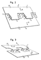
- Fig. 2 to 4 is for producing a metal element on the basis of the pattern after Fig. 1 used a folding process.
- the edge portions of the material web 1 are moved apart in opposite directions according to arrows 14, 15 that the webs 10, 11 are each bent at two bend lines 16, 17 and 18, 19.
- the two by the webs 10, 11 interconnected halves 20, 21 of the material web 1 move apart in a pivoting movement until they turn into the in Fig. 4 shown positions, where they are essentially back in the same plane.
- openings 22, 23 formed.
- the shape of the projections 24, 25 is, except for the web areas, complementary to the shape of the openings 22, 23rd
- the width 12 of the material web 1 has increased by twice the web length to the width 12 '. Essentially no stretching or bending stresses occur in the material of the material web 1 during the expansion or folding process. Only directly in the fold lines 16, 17, 18, 19 takes place by the refolding a bending of the material. The material expansion is negligible compared to the area enlargement.
- the material web 1 has a first edge region 26 adjoining the outer edge 8, a second edge region 27 adjoining the second outer edge 9, and a central region 28 lying between the two edge regions 26, 27, through which the two edge regions 26, 27 are joined together are connected.
- the middle region 28 comprises four sections 29, 30 shown in dashed lines, wherein each of these sections 29, 30 consists of three sections 31, 32, 33 and 34, 35, 36.
- each of these sections 29, 30 consists of three sections 31, 32, 33 and 34, 35, 36.
- the outer sections 31, 33 of the section 29 are hatched opposite obliquely to the middle section 32 lying therebetween.
- the outer portions 34 and 36 of the portions 30 are transversely hatched, while the intermediate central portion 35 is longitudinally hatched with respect to the longitudinal direction of the web 1.
- outer sections does not necessarily mean that these sections are closer to one of the outer edges 8, 9, as the middle sections, but that this term describes the division of the sections 29, 30 in three sections , wherein the "outer” sections are each the subsections which are interconnected by a common intermediate section lying between them .
- the material web 1 can be guided by a rolling device after completion of the folding process.
- the material which is triple-layered in the middle region 28 is compressed, at the same time resulting in work hardening of the material.
- the rolling process thus produces, on the one hand, a substantially flat surface 13 and, on the other hand, increased stability of the material web 1 also in the region of the crease lines 16, 17, 18, 19 and the relatively thin webs 10, 11, which form the middle sections 32, 35 form reached.
- FIGS Fig. 1 to 4 corresponds essentially to the Fig. 1 to 4 described embodiment, see that the same reference numerals as in FIGS Fig. 1 to 4 be used.
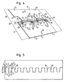
- the embodiment according to the Fig. 5 to 8 differs from the embodiment according to the Fig. 1 to 4 only in that between the U-shaped slots 2, 3 each have two more obliquely extending slots 37, 38 are provided. Because of these further slots 37, 38, two webs 10, 10 'and 11, 11', which are arranged one behind the other parallel to the direction of expansion according to the arrows 14, 15, are formed.
- the folding process is identical to that of the Fig. 2 to 4 described folding process.
- Advantageous to the embodiment according to the Fig. 5 to 8 is that an even higher stability of the expanded material web 1 is given by the additional webs 10 ', 11'.
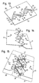
- Fig. 9 shows an embodiment in which instead of the U-shaped slots 2, 3 V-shaped slots 37, 38 are cut into the material web 1. Similar to the U-shaped slots 2, 3 and the V-shaped slots 37, 38 are each juxtaposed in the longitudinal direction of the web 1 and offset arranged interlocking.
- the V-shaped slots 37, 38 have legs 39, 40 which overlap one another, so that in each case webs 10, 11 are formed between the legs 39, 40.
- the material web 1 is in accordance with 10 to 12 in an identical way as already to the Fig. 2 to 4 described along two arrows 14, 15 moved apart, so that the width 12 of the web 1 after completion of the folding process to an enlarged width 12 'is expanded.
- the resulting width 12 'of the web 1 is identical in both cases, in which the Fig. 13 to 15 Only the number of creases 43, 44 are reduced.
- the material web 1 is fed to a smoothing device, with which the multilayer material sections are pressed together.
- the crease lines have been selected in an identical manner on both sides of the central region 28, it is in principle also possible, for example, the crease lines on one side of the central region 28 according to the embodiment of the 10 to 12 and on the other side of the central region 28 according to the embodiment according to FIGS Fig. 13 to 15 to choose.
- the flexural rigidity can also be increased by arranging successive sections 29, 30 along the length of the metal element not exclusively along a straight line, in particular in the longitudinal direction of the metal element, but rather that at least some sections 29, 30 are arranged laterally offset from one another. While in the embodiment according to Fig. 4 all sections 29, 30 follow one another in a straight line are in the embodiment according to Fig. 8 each lying closer to the outer edge 8 sections 29, 30 arranged laterally offset relative to the closer to the outer edge 9 lying portions 29, 30, so that the embodiment according to Fig. 8 has a greater flexural rigidity than that Fig. 4 , It would also be possible, for example, in the embodiment Fig. 4 to displace the sections 29 laterally relative to the sections 30 or to laterally displace a respective pair of sections 29, 30 relative to the next pair of sections 29, 30, thereby achieving increased flexural rigidity.
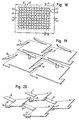
- Fig. 16 shows the pattern according to Fig. 9 , wherein instead of a single double row of V-shaped slots 37, 38, a plurality of such interlocking V-shaped slots are provided.
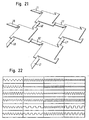
- Fig. 18 shows a pattern that allows expansion of the web 1 both along the arrows 14, 15 and at the same time along both arrows 45, 46 allows. With this pattern, a material expansion is thus possible not only along one axis, but along two mutually perpendicular axes.
- Fig. 22 Other possible patterns are in Fig. 22 shown.
- all pointed edges can also be replaced, for example, by corresponding curves.
- a multiple graduation as for example Fig. 5 in contrast to Fig. 1 shows, even with the patterns after Fig. 22 possible.
- FIGS. 23 and 24 two application examples of the invention shown.
- Fig. 23 schematically shows a corner profile 51, as used for example as a plaster profile.
- the corner profile 51 is formed as an L-shaped angle profile, wherein both legs of the angular corner profile 51 are provided with openings 22, 23 according to the invention. Through the openings 22, 23 it is ensured that the plaster used for plastering the corner profile 51 can pass through the corner profile 51 and thus a secure attachment of the corner profile 51 is ensured.
- Fig. 24 shows two uprights 52, which are each formed as C-shaped angle profiles. While the two legs 53, 54, to which, for example, a plate 55 is fastened with screws 56 are formed in the usual way as a solid material, the two base portions 57 of the stator profiles 52 are produced as inventively designed metal elements and provided with the corresponding openings 22, 23 , In this way it is ensured that the material consumption for the production of the stator profiles 53 is significantly reduced compared to conventional methods.
Description
Die vorliegende Erfindung betrifft ein flächiges Metallelement nach dem Oberbegriff des Anspruchs 1 sowie ein Verfahren zu dessen Herstellung. Weiterhin ist die Erfindung auf ein Profilelement gerichtet, das aus einem solchen flächigen Metallelement hergestellt wird.The present invention relates to a sheet metal element according to the preamble of
Flächige Metallelemente der eingangs genannten Art werden beispielsweise bei der Herstellung von Profilen verwendet. Solche Profile können beispielsweise Ständerprofile sein, wie sie insbesondere beim Innenausbau zum Befestigen von plattenförmigen Elementen verwendet werden, oder auch Eckprofile, die zum Schutz von Ecken meist unter Putz eingesetzt werden. Insbesondere für solche Putzprofile ist es erforderlich, dass diese Profile Materialdurchbrechungen besitzen, damit der Putz durch die Profile hindurch dringen kann und somit eine Festlegung der Profile gewährleistet ist.Flat metal elements of the type mentioned are used for example in the production of profiles. Such profiles can be, for example, uprights, as they are used in particular for interior installation for fixing plate-shaped elements, or corner profiles, which are usually used to protect corners under plaster. In particular, for such plaster profiles, it is necessary that these profiles have material breakthroughs, so that the plaster can penetrate through the profiles and thus a determination of the profiles is guaranteed.
Üblicherweise werden solche Durchbrechungen durch Stanzvorgänge hergestellt, so dass die herausgestanzten Teile Abfall bilden. Dies ist zum einen nachteilig, da diese Teile entweder entsorgt oder der Wiederverwertung zugeführt werden müssen. Zum anderen liegt ein wesentlicher Nachteil darin, dass die Kosten bei der Herstellung eines entsprechenden Profils in überwiegendem Maße durch die Materialkosten bestimmt werden. Ein Ausstanzen von Teilflächen ist somit unwirtschaftlich, insbesondere wenn die ausgestanzten Teilflächen als Abfall entsorgt werden müssen.Usually such openings are made by punching operations, so that the punched out parts form waste. This is on the one hand disadvantageous because these parts must either be disposed of or recycled. On the other hand, a significant disadvantage is that the costs in the production of a corresponding profile are predominantly determined by the material costs. A punching of faces is therefore uneconomical, especially if the punched faces must be disposed of as waste.
Um diesen Nachteil zu umgehen, ist es bereits bekannt, Lochprofile aus Streckmetall herzustellen. Bei der Verwendung von Streckmetall werden in das zur Herstellung der Profile verwendete Metallblech Schlitze so eingeschnitten, dass anschließend das Metallblech an zwei entgegengesetzten Seiten auseinander gezogen wird, wobei sich die Schlitze zu den gewünschten Durchbrechungen aufweiten. Das zwischen den Durchbrechungen liegende Material wird dabei gestreckt bzw. gedehnt, wodurch die gewünschte Verformung und damit verbunden eine Materialverbreiterung erfolgt. Durch die Streckung des Materials entstehen jedoch Spannungen in dem Material, die zu einer unerwünschten Schwächung führen können. Auch ist die Biegesteifigkeit von Streckmetall verringert, so dass Streckmetall in vielen Bereichen nicht einsetzbar ist. Letztlich sind auch die mit dem Streckmetall erzielten Materialverbreiterungen oftmals nicht ausreichend.To avoid this disadvantage, it is already known to produce hole profiles of expanded metal. When expanded metal is used, slots are cut into the metal sheet used to make the profiles so that subsequently the metal sheet is pulled apart on two opposite sides, widening the slots to the desired apertures. The material lying between the apertures is thereby stretched or stretched, whereby the desired deformation and associated material broadening takes place. However, stretching the material creates stresses in the material that can lead to undesirable weakening. Also, the flexural rigidity of expanded metal is reduced so that expanded metal can not be used in many areas. Ultimately, the material broadening achieved with the expanded metal is often insufficient.
Aus der
Es ist eine Aufgabe der vorliegenden Erfindung, ein flächiges Metallelement der eingangs genannten Art so auszubilden, dass die Durchbrechungen ohne Materialverlust ausgebildet sind, wobei gleichzeitig innerhalb des Materials im Wesentlichen keine Spannungen vorhanden sein sollen. Weiterhin soll das Metallelement eine hohe Steifigkeit besitzen und es soll, gegenüber dem Ausgangsmaterial eine große Materialverbreiterung bzw. Flächenausdehnung möglich sein.It is an object of the present invention, a flat metal element of the type mentioned in such a way that the openings are formed without loss of material, while at the same time substantially no stresses should be present within the material. Furthermore, the metal element should have a high rigidity and it should, compared to the starting material a large material broadening or area expansion be possible.
Ausgehend von einem Metallelement der eingangs genannten Art wird diese Aufgabe erfindungsgemäß durch die Merkmale des Anspruchs 1 gelöst.Starting from a metal element of the type mentioned, this object is achieved by the features of
Erfindungsgemäß sind somit die Durchbrechungen in dem flächigen Metallelement nicht durch einen Streckvorgang erzeugt, sondern durch ein Umfalten von Teilabschnitten, so dass eine Dehnung oder eine Streckung innerhalb des Metallelements, wie sie bei Streckmetall vorhanden ist, vermieden wird. Die umgefalteten Teilabschnitte sind dabei so angeordnet, dass während des Arbeitsgangs ein Auseinanderfalten der beiden äußeren Randbereiche des Metallelements erfolgt, wodurch die gewünschte Materialverbreiterung bzw. Expansion erreicht wird. Gleichzeitig wird durch das Umfalten und die einstückige Ausbildung des Metallelements gewährleistet, dass die Durchbrechungen in dem Metallelement in einem einstückigen Herstellungsprozess erzeugbar sind und die gewünschte Steifigkeit und Stabilität gewährleistet sind. Durch die Anordnung von mehreren, zwischen den Außenkanten des Metallelements hintereinander liegenden umgefalteten Abschnitten wird die Steifigkeit des Metallelements erhöht.According to the invention, the apertures in the flat metal element are thus not produced by a stretching process, but by a folding over of sections, so that an elongation or an extension within the metal element, as it is present in expanded metal, is avoided. The folded-over sections are arranged so that unfolding of the two outer edge regions of the metal element occurs during the operation, whereby the desired material broadening or expansion is achieved. At the same time is ensured by the folding and the integral formation of the metal element, that the openings in the metal element in an integral manufacturing process can be generated and the desired rigidity and stability are ensured. By arranging a plurality of folded sections arranged one behind the other between the outer edges of the metal element, the rigidity of the metal element is increased.
Nach einer vorteilhaften Ausführungsform der Erfindung sind die außen liegenden Teilabschnitte gegensinnig zueinander, das heißt in einander entgegengesetzten Richtungen umgefaltet. Dabei ist insbesondere einer der außen liegenden Teilabschnitte zur Oberseite des mittleren Teilabschnitts und der andere außen liegende Teilabschnitt zur Unterseite des mittleren Teilabschnitts hin umgefaltet. Die Teilabschnitte können dabei sowohl zueinander zeigend als auch auseinander zeigend umgefaltet sein.According to an advantageous embodiment of the invention, the outer sections are opposite to each other, that is, folded in opposite directions. In particular, one of the outer sections is at the top of the middle section and the other outer portion folded over to the underside of the central portion. The sections can be folded both facing each other and pointing apart.
Grundsätzlich ist es auch möglich, dass die außen liegenden Teilabschnitte gleichsinnig zueinander, das heißt in die gleiche Richtung zeigend umgefaltet sind. Insbesondere sind hierbei beide außen liegende Teilabschnitte zur selben Seite, das heißt beide entweder zur Oberseite oder beide zur Unterseite des mittleren Teilabschnitts hin umgefaltet.In principle, it is also possible for the outer sections to be folded in the same direction relative to one another, that is to say in the same direction. In particular, in this case both outer sections are folded to the same side, that is, both folded either to the top or both to the bottom of the central portion.
Nach einer weiteren vorteilhaften Ausführungsform der Erfindung sind zumindest in einem der Randbereiche mehrere Durchbrechungen ausgebildet. Dies ist insbesondere dann sinnvoll, wenn das flächige Metallelement eine in Richtung der Außenkanten sich erstreckende lang gestreckte Ausbildung besitzt, da nur durch die Durchbrechungen eine entsprechende Verbreiterung des Metallelements über dessen gesamte Länge möglich ist. Vorteilhaft sind in jedem der Randbereiche mehrere Durchbrechungen ausgebildet. Diese Durchbrechungen sind dabei bevorzugt alternierend in den beiden Randbereichen verteilt, wobei bevorzugt jeweils ein Abschnitt mit seinen umgefalteten außen liegenden Teilabschnitten gleichzeitig jeweils einer Durchbrechung des ersten und einer sich daran anschließenden Durchbrechung des zweiten Randbereichs zugeordnet ist.According to a further advantageous embodiment of the invention, a plurality of apertures are formed at least in one of the edge regions. This is particularly useful if the flat metal element has an elongated design extending in the direction of the outer edges, since only through the openings a corresponding broadening of the metal element over its entire length is possible. Advantageously, a plurality of apertures are formed in each of the edge regions. These openings are preferably distributed alternately in the two edge regions, wherein preferably each one section is associated with its folded outer sections at the same time each an opening of the first and an adjoining opening of the second edge region.
Nach einer weiteren vorteilhaften Ausführungsform der Erfindung sind in dem Mittelbereich zusätzliche Durchbrechungen ausgebildet. Dabei sind vorteilhaft die in dem Mittelbereich ausgebildeten Durchbrechungen entsprechend den in den Randbereichen ausgebildeten Durchbrechungen ausgebildet. Es ist somit möglich, eine zusätzliche Verbreiterung des Metallelements dadurch zu erreichen, dass mehrere erfindungsgemäß umgefaltete Abschnitte zwischen den Außenkanten hintereinander liegend vorgesehen sind.According to a further advantageous embodiment of the invention additional openings are formed in the central region. In this case, the apertures formed in the middle region are advantageously designed in accordance with the apertures formed in the edge regions. It is thus possible to achieve an additional broadening of the metal element in that several according to the invention folded portions are provided between the outer edges lying one behind the other.
Vorteilhaft ist ein Abschnitt als Steg mit parallel zueinander verlaufenden Seitenkanten ausgebildet. Grundsätzlich können die Seitenkanten des Abschnitts jedoch auch schräg zueinander verlaufen oder beispielsweise auch gekrümmt ausgebildet sein, solange das erfindungsgemäße Umklappen der Teilabschnitte dadurch nicht verhindert wird. Insbesondere an den Enden der Abschnitte können dabei von der Stegform abweichende, beispielsweise seitlich abstehende Flächen vorgesehen sein.Advantageously, a portion is formed as a web with mutually parallel side edges. In principle, however, the side edges of the section can also run obliquely to one another or, for example, can also be curved, as long as the folding over of the partial sections according to the invention is not prevented thereby. In particular, at the ends of the sections may be provided deviating from the web shape, for example, laterally projecting surfaces.
Nach einer weiteren bevorzugten Ausführungsform der Erfindung verlaufen die Seitenkanten und die Stege parallel zueinander oder schräg zueinander. Auch hier ist die Geometrie lediglich dadurch eingeschränkt, dass ein Umfalten der außen liegenden Teilabschnitte und damit ein Auseinanderklappen der beiden Randbereiche nicht behindert wird.According to a further preferred embodiment of the invention, the side edges and the webs parallel to each other or obliquely to each other. Again, the geometry is limited only by the fact that a folding of the outer sections and thus a unfolding of the two edge regions is not hindered.
Durch die Erfindung wird erreicht, dass der Abstand zwischen der ersten und der zweiten Außenkante mit umgefalteten Teilabschnitten deutlich größer ist als mit nicht umgefalteten Teilabschnitten. Auf diese Weise wird die gewünschte Materialverbreiterung erreicht. Insbesondere ist es mit der Erfindung möglich, dass der Abstand mit umgefalteten Teilabschnitten ca. zwischen 1,3 und 4 Mal, insbesondere ca. zwischen 2 und 3 Mal so groß ist wie mit nicht umgefalteten Teilabschnitten. Somit ist bei erfindungsgemäß ausgebildeten Metallelementen durch die erfindungsgemäße Faltung eine deutlich größere Expansion möglich als sie beispielsweise bei der Verwendung von Streckmetall erreicht werden kann.By the invention it is achieved that the distance between the first and the second outer edge with folded-over sections is significantly greater than with unfolded sections. In this way, the desired material broadening is achieved. In particular, it is possible with the invention that the distance with fold-over sections approximately between 1.3 and 4 times, in particular approximately between 2 and 3 times as large as unenfolded sections. Thus, in the case of metal elements formed according to the invention, a significantly greater expansion is possible by the folding according to the invention than can be achieved, for example, when using expanded metal.
Vorteilhaft wiederholen sich die Durchbrechungen in regelmäßigen Abständen, wobei dies sowohl für die in den Randbereichen ausgebildeten Durchbrechungen als auch für eventuell in dem Mittelbereich ausgebildete Durchbrechungen gilt. Grundsätzlich können sich die Durchbrechungen auch in unregelmäßigen Abständen wiederholen.Advantageously, the openings are repeated at regular intervals, and this is the case for both in the edge regions Breakthroughs as well as for possibly formed in the middle region openings applies. In principle, the openings can also repeat at irregular intervals.
Nach einer weiteren vorteilhaften Ausführungsform der Erfindung besitzen die Randbereiche mit Ausnahme der Durchbrechungen eine im Wesentlichen ebene Oberfläche. Vorteilhaft ist auch die Oberfläche des Metallelements mit Ausnahme der Durchbrechungen im Wesentlichen eben ausgebildet. Dies kann beispielsweise dadurch erreicht werden, dass die durch das Umfalten vorhandenen Materialverdickungen flach gewalzt werden. Dadurch entsteht zusätzlich an den Biegelinien sowie an den dünn gewalzten umgefalteten Teilabschnitten eine Kaltverfestigung, so dass trotz der Faltung des Materials die Steifigkeit der umgefalteten Abschnitte zumindest der Steifigkeit des Ausgangsmaterials entspricht. Dies ist insbesondere dann wichtig, wenn die beispielsweise als Stege ausgebildeten Abschnitte relativ dünn ausgebildet sind, da in diesem Fall durch die Kaltverfestigung trotz dieser dünnen Verbindungsstellen zwischen den beiden Randbereichen eine hohe Steifigkeit des gesamten Metallelements gewährleistet ist.According to a further advantageous embodiment of the invention, the edge regions, with the exception of the apertures, have a substantially planar surface. Advantageously, the surface of the metal element with the exception of the openings is substantially flat. This can be achieved, for example, by flat-rolling the material thickenings present due to the folding over. This results in addition to the bending lines and the thin rolled folded sections a strain hardening, so that despite the folding of the material, the rigidity of the folded portions at least equal to the rigidity of the starting material. This is particularly important if the formed for example as webs sections are made relatively thin, since in this case, a high rigidity of the entire metal element is ensured by the work hardening despite these thin connection points between the two edge regions.
Nach einer weiteren vorteilhaften Ausführungsform der Erfindung schließen die umgefalteten außen liegenden Teilabschnitte mit dem mittleren Teilabschnitt jeweils einen Winkel von ca. 110° bis 0°, vorzugsweise von ca. 90° bis 0°, vorteilhaft von ca. 45° bis 0°, insbesondere von 10° bis 0° ein. Zum Erzeugen eines flächigen, verbreiterten Metallelements werden die außen liegenden Teilabschnitte vollständig umgefaltet, so dass sie mit dem mittleren Teilabschnitt einen Winkel von ca. 0° einschließen. Grundsätzlich ist es jedoch auch möglich, dass der Faltvorgang nicht bis zum vollständigen Umklappen durchgeführt wird, so dass sich dreidimensionale Strukturen erzeugen lassen. Diese sind beispielsweise bei der Erzeugung von Verbundwerkstoffen, Filtern oder dergleichen verwendbar.According to a further advantageous embodiment of the invention, the folded outer sections with the middle section in each case close an angle of about 110 ° to 0 °, preferably from about 90 ° to 0 °, preferably from about 45 ° to 0 °, in particular from 10 ° to 0 °. To produce a flat, widened metal element, the outer sections are completely folded over, so that they enclose an angle of approximately 0 ° with the central section. In principle, however, it is also possible that the folding process is not carried out until complete folding, so that three-dimensional Create structures. These can be used, for example, in the production of composites, filters or the like.
Nach einer weiteren vorteilhaften Ausführungsform der Erfindung geht jeder der umgefalteten außen liegenden Teilabschnitte, der direkt mit einem Randbereich verbunden ist, kontinuierlich, insbesondere eben in den mit ihm verbundenen Randbereich über. Dadurch wird in diesem Bereich eine glatte bzw. ebene Oberfläche des Metallelements ohne Kanten, Biegungen oder dergleichen erreicht.According to a further advantageous embodiment of the invention, each of the folded outer sections, which is directly connected to an edge region, continuously, in particular just in the associated with him edge region over. As a result, a smooth or even surface of the metal element without edges, bends or the like is achieved in this area.
Nach einer weiteren bevorzugten Ausführungsform der Erfindung schließt sich an die erste und/ oder an die zweite Außenkante jeweils ein weiterer Metallabschnitt an, der zusammen mit dem sich zwischen der ersten und der zweiten Außenkante erstreckenden Material ein Winkelprofil bildet. Insbesondere kann das Winkelprofil dabei L-förmig, V-förmig, U-förmig, C-förmig oder Z-förmig ausgebildet sein. Durch diese Ausbildung kann das flächige Metallelement einfach zur Bildung eines Profils verwendet werden. Der oder die weiteren Metallabschnitte können dabei entweder vollflächig ausgebildet sein oder, falls gewünscht, ebenfalls mit erfindungsgemäßen Durchbrechungen durchsetzt sein. Soll beispielsweise ein Putzprofil erzeugt werden, so wird das Winkelprofil vorteilhaft L-förmig ausgebildet, wobei bevorzugt beide Schenkel des Profils mit erfindungsgemäßen Durchbrechungen versehen sind. Handelt es sich bei dem Winkelprofil hingegen beispielsweise um ein Ständerprofil, so ist eine C-förmige, U-förmige, T-förmige, I-förmige oder Z-förmige Ausbildung vorteilhaft, wobei die Durchbrechungen lediglich in dem mittleren Basisteil, nicht jedoch in den außen liegenden Schenkeln vorhanden sind. Bei Bedarf können die Durchbrechungen auch direkt in den Biegelinien der Winkelprofile oder nur in einem oder mehreren Schenkeln ausgebildet sein.According to a further preferred embodiment of the invention, in each case another metal section adjoins the first and / or the second outer edge, which forms an angle profile together with the material extending between the first and the second outer edge. In particular, the angle profile may be L-shaped, V-shaped, U-shaped, C-shaped or Z-shaped. With this design, the sheet metal element can be easily used to form a profile. The one or more metal sections may be formed either over the entire surface or, if desired, also be penetrated with openings according to the invention. If, for example, a plaster profile is to be produced, then the angle profile is advantageously designed in the shape of an L, wherein preferably both legs of the profile are provided with apertures according to the invention. If, however, the angle profile, for example, a stand profile, so a C-shaped, U-shaped, T-shaped, I-shaped or Z-shaped configuration is advantageous, the openings in the middle base part, but not in the outer thighs are present. If necessary, the openings can also be formed directly in the bending lines of the angle profiles or only in one or more legs.
Grundsätzlich kann das erfindungsgemäße Metallelement überall eingesetzt werden, wo flächige Metallabschnitte eingesetzt werden, so z.B. bei allen Arten von offenen oder geschlossenen Metallprofilen, wie z.B. auch Rohrprofilen.In principle, the metal element according to the invention can be used everywhere, where flat metal sections are used, e.g. in all types of open or closed metal profiles, e.g. also tube profiles.
Bevorzugt ist der weitere Metallabschnitt oder sind die weiteren Metallabschnitte einstückig mit dem restlichen Teil des Metallelements ausgebildet, um auf diese Weise den einstufigen Herstellvorgang beizubehalten.Preferably, the further metal portion or the further metal portions are formed integrally with the remaining part of the metal element, in order to maintain the single-stage manufacturing process in this way.
Nach einer weiteren bevorzugten Ausführungsform der Erfindung sind zusätzlich zu den ersten und zweiten Randbereichen ein dritter und ein vierter Randbereich vorhanden, die sich gegenüberliegen und sich jeweils quer, insbesondere senkrecht zu dem ersten oder zweiten Randbereich erstrecken. Die Ausbildung der Oberfläche der Materialbahn entspricht dabei in einer Richtung von dem dritten zu dem vierten Randbereich im Wesentlichen der Ausbildung der Oberfläche in einer Richtung von dem ersten zu dem zweiten Randbereich. Auf diese Weise ist somit eine Materialverbreiterung nicht nur in einer Richtung, insbesondere quer zur Längserstreckung des Metallelements, sondern beispielsweise in zwei senkrecht zueinander liegenden Richtungen, beispielsweise eine längs zur Längserstreckung und eine quer zur Längserstreckung des Metallelements möglich. Bei dieser Ausführungsform wird somit eine zweidimensionale Expansion und Materialverbreiterung erzielt.According to a further preferred embodiment of the invention, in addition to the first and second edge regions, a third and a fourth edge region are present, which lie opposite each other and each extending transversely, in particular perpendicular to the first or second edge region. The formation of the surface of the material web in this case corresponds in one direction from the third to the fourth edge region essentially to the formation of the surface in a direction from the first to the second edge region. In this way, a material widening is thus possible not only in one direction, in particular transversely to the longitudinal extent of the metal element, but for example in two mutually perpendicular directions, for example, one longitudinal to the longitudinal extent and one transverse to the longitudinal extent of the metal element. In this embodiment, therefore, a two-dimensional expansion and material broadening is achieved.
Das erfindungsgemäße Metallelement kann vielfältig verwendet werden. Beispielsweise kann das Metallelement als Profilelement, insbesondere als Eck- oder Ständerprofil, als Schutzgitter, als Zaunabschnitt, als Filtermatte, als Schallschutzelement, als Rankgerüst, als Trittflächenelement, als Bewehrungsmatte, als Einlage in Verbundwerkstoffen, als Kabelkanal, als Lochband, als Montage-, Akustik- oder Abschattungselement oder als Zierprofil verwendet werden. Dabei ist es jeweils möglich, dass die entsprechenden Elemente vollständig durch das erfindungsgemäße Metallelement gebildet sind oder dass, wie bereits beschrieben, sich an das die Durchbrechungen enthaltene Metallelement weitere Metallabschnitte anschließen.The metal element according to the invention can be used in many ways. For example, the metal element as a profile element, in particular as a corner or upright profile, as a protective grid, as a fence section, as a filter mat, as a soundproofing element, as a trellis, as tread element, as a reinforcing mat, as an insert in composite materials, as a cable duct, as a perforated tape, as an assembly, Acoustic or shading element or as Decorative profile can be used. In this case, it is possible in each case for the corresponding elements to be formed completely by the metal element according to the invention or, as already described, to connect further metal sections to the metal element which contains the openings.
Grundsätzlich kann die Erfindung in allen Bereichen eingesetzt werden, in denen flächige Werkstoffe perforiert, gelocht, oder gestanzt werden, um zum Beispiel eine Durchlässigkeit oder Teildurchlässigkeit bzw. gerichtete Reflexion für Licht, Schall oder Fluide zu erreichen. Mit der Erfindung wird erreicht, dass anders als beispielsweise bei einer Perforation bei der Erzeugung der Durchbrechungen kein Materialausschuss entsteht und somit Kosten reduziert werden können. Weitere Einsatzgebiete können sein: Verwendung bei Drahtglas, Sandwichböden, Verpackungs-Dämmungsmaterial, Deckenabhänger, Kabeltragsysteme, Katalysatorbleche, Leitungsführungssysteme, Lochbleche, Lochstreifen, Montagebänder, Montagewinkel, Regalträger, Rispenbänder, Rolladenprofile, Pfostenträger, Profilbänder, Schienensysteme, Schlitzbänder, Strebenverbinder, Tragschienen oder Netzherstellung.In principle, the invention can be used in all areas in which sheet materials are perforated, perforated, or punched, for example, to achieve a permeability or partial transmission or directional reflection for light, sound or fluids. With the invention it is achieved that, unlike, for example, in the case of a perforation in the production of the perforations, no scrap of material is produced and thus costs can be reduced. Further areas of application may be: use in wire glass, sandwich panels, packaging insulation material, ceiling suspensions, cable support systems, catalyst plates, cable routing systems, perforated plates, perforated strips, mounting strips, mounting brackets, shelf supports, pan strips, shutter profiles, post carriers, profile strips, rail systems, slotted strips, strut connectors, mounting rails or mesh production ,
Typische Dicken der verwendeten Materialbahnen liegen dabei zwischen ca. 0,3 mm bis 2 mm, insbesondere zwischen ca. 0,4 mm und 0,8 mm. Als Material kann beispielsweise Aluminium, Zinkblech, Edelstahl oder verzinktes Stahlblech verwendet werden. Allerdings ist die Erfindung nicht auf diese Dickenwerte bzw. Materialien beschränkt.Typical thicknesses of the material webs used are between about 0.3 mm to 2 mm, in particular between about 0.4 mm and 0.8 mm. As a material, for example, aluminum, zinc sheet, stainless steel or galvanized steel sheet can be used. However, the invention is not limited to these thickness values or materials.
Weitere vorteilhafte Ausführungsformen sind in den Unteransprüchen angegeben.Further advantageous embodiments are specified in the subclaims.
Die Erfindung wird nachfolgend anhand von Ausführungsbeispielen unter Bezugnahme auf die Figuren näher beschrieben, wobei es sich bei den
- Fig. 1
- ein Schnittmuster mit dem ein Metallelement herstellbar ist,
- Fig. 2 - 4
- drei unterschiedliche Zustände während des Herstellens eines Metallelements nach dem Schnittmuster gemäß
Fig. 1 , - Fig. 5
- ein Schnittmuster zur Herstellung eines erfindungsgemäß ausgebildeten Metallelements,
- Fig. 6 - 8
- drei Verfahrensschritte zum Herstellen eines erfindungsgemäß ausgebildeten Metallelements nach einem Schnittmuster gemäß
Fig. 5 , - Fig. 9
- ein weiteres Schnittmuster,
- Fig. 10 - 12
- drei Verfahrensschritte zum Herstellen eines Metallelements nach dem Schnittmuster gemäß
Fig. 9 , - Fig. 13-15
- drei alternative Verfahrensschritte bei der Herstellung des Metallelements gemäß dem Schnittmuster aus
Fig. 9 , - Fig. 16
- ein weiteres Schnittmuster,
- Fig. 17
- ein erfindungsgemäß ausgebildetes Metallelement, das gemäß dem Schnittmuster nach
Fig. 16 hergestellt wurde, - Fig. 18
- ein weiteres Schnittmuster,
- Fig. 19 - 21
- drei Verfahrensschritte zur Herstellung eines Metallelements nach dem Schnittmuster gemäß
Fig. 18 , - Fig. 22
- weitere Varianten unterschiedlicher Schnittmuster,
- Fig. 23
- eine schematische Darstellung eines Eckprofils gemäß der Erfindung und
- Fig. 24
- eine schematische Darstellung eines erfindungsgemäß ausgebildeten Ständerprofils.
- Fig. 1
- a pattern with a metal element can be produced,
- Fig. 2-4
- three different states during the production of a metal element according to the cutting pattern according to
Fig. 1 . - Fig. 5
- a cutting pattern for producing a metal element according to the invention,
- Fig. 6-8
- three method steps for producing a metal element designed according to the invention according to a pattern according to
Fig. 5 . - Fig. 9
- another pattern,
- Fig. 10 - 12
- three method steps for producing a metal element according to the pattern according to
Fig. 9 . - Fig. 13-15
- three alternative process steps in the production of the metal element according to the pattern from
Fig. 9 . - Fig. 16
- another pattern,
- Fig. 17
- a metal element according to the invention, which according to the pattern according to
Fig. 16 was produced, - Fig. 18
- another pattern,
- Fig. 19 - 21
- three process steps for producing a metal element according to the pattern according to
Fig. 18 . - Fig. 22
- other variants of different patterns,
- Fig. 23
- a schematic representation of a corner profile according to the invention and
- Fig. 24
- a schematic representation of an inventively designed stator profile.
Die Schlitze 2, 3 sind jeweils U-förmig ausgebildet, wobei die beiden Schenkel 4, 5 zur offenen Seite des U hin auseinander laufen.The
Die Schenkel 4 wie auch die Schenkel 5 sind jeweils durch linienförmige Basisschnitte 6, 7 miteinander verbunden, die jeweils parallel zueinander angeordnet sind.The legs 4 as well as the
Die U-förmigen Schlitze 2 liegen jeweils in gleicher Höhe, periodisch aufeinander folgend entlang der Längsachse der Materialbahn 1 hintereinander. Ebenso liegen die U-förmigen Schlitze 3 entlang der Längsachse der Materialbahn 1 in gleichmäßigen Abständen aufeinander folgend hintereinander, wobei jedoch die offenen Seiten der U-förmigen Schlitze 2 und 3 zu der jeweils anderen Außenkante 8, 9 der Materialbahn 1 zeigen. Dabei sind die U-förmigen Schlitze 2, 3 so ineinander greifend angeordnet, dass sich die Schenkel 4, 5 jeweils überlappen und zwischen den Schenkeln 4, 5 Stege 10, 11 ausgebildet sind.The
Die Materialbahn 1 besitzt eine Oberfläche 13 mit einer Breite 12, die sich von der Außenkante 8 zur Außenkante 9 erstreckt.The
Gemäß den
Nach dem vollständigen Verschwenken und dem daraus resultierenden Auseinanderziehen der Hälften 20, 21 der Materialbahn 1 sind in dieser, wie aus
Durch den Expansionsvorgang hat sich die Breite 12 der Materialbahn 1 um die zweifache Steglänge auf die Breite 12' vergrößert. Dabei treten während des Expansions- bzw. Faltvorgangs im Wesentlichen keine Streck- oder Biegespannungen in dem Material der Materialbahn 1 auf. Lediglich unmittelbar in den Knicklinien 16, 17, 18, 19 erfolgt durch die Umfaltung eine Biegung des Materials. Dabei ist die Materialdehnung gegenüber der Flächenvergrößerung vernachlässigbar.Due to the expansion process, the
In der in
Der Mittelbereich 28 umfasst vier gestrichelt dargestellte Abschnitte 29, 30, wobei jeder dieser Abschnitte 29, 30 aus drei Teilabschnitten 31, 32, 33 bzw. 34, 35, 36 besteht. Zur Verdeutlichung sind in
Wie aus
Dabei wird darauf hingewiesen, dass der Begriff "außen liegende" Teilabschnitte nicht notwendigerweise bedeutet, dass diese Teilabschnitte näher an einer der Außenkanten 8, 9 liegen, als die mittleren Teilabschnitte, sondern dass dieser Begriff die Einteilung der Abschnitte 29, 30 in drei Teilabschnitte beschreibt, wobei die "außen liegenden" Teilabschnitte jeweils die Teilabschnitte sind, die durch einen gemeinsamen, zwischen ihnen liegenden mittleren Teilabschnitt miteinander verbunden sind.It should be noted that the term "outer" sections does not necessarily mean that these sections are closer to one of the
Um eine möglichst glatte Oberfläche 13 zu erhalten, kann nach Beendigung des Faltvorgangs die Materialbahn 1 durch eine Walzvorrichtung geführt werden. Durch entsprechend hohen Druck beim Walzvorgang wird das im Mittelbereich 28 dreilagige Material zusammengepresst, wobei gleichzeitig eine Kaltverfestigung des Materials entsteht. Durch den Walzvorgang wird somit zum einen eine weitgehend ebene Oberfläche 13 erzeugt und zum andern eine erhöhte Stabilität der Materialbahn 1 auch im Bereich der Knicklinien 16, 17, 18, 19 sowie der relativ dünn ausgebildeten Stege 10, 11, welche die mittleren Teilabschnitte 32, 35 bilden, erreicht.In order to obtain the smoothest
Das in den
Das Ausführungsbeispiel gemäß den
Der Faltvorgang erfolgt identisch zu dem zu den
Weiterhin ist in
Die Materialbahn 1 wird gemäß den
Bei dem in den
Im Gegensatz dazu werden bei dem in den
Die resultierende Breite 12' der Materialbahn 1 ist in beiden Fällen identisch, bei der zu den
Wie bereits zu der Ausführungsform gemäß den
Während sowohl bei den Ausführungen nach den
Bezogen auf die Ausführungsformen gemäß den
Bei den Ausführungsformen, bei denen die Biegelinien zweier aneinander angrenzender außen liegender Teilabschnitte voneinander getrennt sind (siehe z.B.
Die Biegesteifigkeit kann auch dadurch erhöht werden, dass über die Länge des Metallelements aufeinander folgende Abschnitte 29, 30 nicht ausschließlich entlang einer geraden Linie, insbesondere in Längsrichtung des Metallelements angeordnet sind, sondern dass zumindest einige Abschnitte 29, 30 seitlich versetzt zueinander angeordnet sind. Während bei dem Ausführungsbeispiel nach
Bei einer solchen Aneinanderreihung von V-förmigen Schlitzen 37, 38 ergibt sich nach der Expansion der Materialbahn letztlich die in
Ähnlich wie zu den
In diesem Fall sind neben Stegen 10, 10', 11, 11', die sich zwischen den Außenkanten 8, 9 hintereinander liegend erstrecken, darüber hinaus senkrecht zu diesen Stegen angeordnete Stege 47, 47', 48, 48' ausgebildet, wie es aus den
Weitere mögliche Schnittmuster sind in
Einheitlich bei allen Schnittmustern ist, dass die beim Faltvorgang entstehenden Knicklinien immer senkrecht zu der Expansionsrichtung ausgerichtet sind.Uniform for all patterns is that the fold lines created during the folding process are always aligned perpendicular to the direction of expansion.
Letztlich sind in den
Durch die erfindungsgemäße Ausbildung des Eckprofils 51 mittels eines erfindungsgemäß expandierten Metallelements wird gleichzeitig der Materialbedarf für die Fertigung des Eckprofils verringert und die erforderliche Steifigkeit des Eckprofils gewährleistet.Due to the inventive design of the
- 11
- Materialbahnweb
- 22
- Schlitzeslots
- 33
- Schlitzeslots
- 44
- Schenkelleg
- 55
- Schenkelleg
- 66
- Basisschnittebase cuts
- 77
- Basisschnittebase cuts
- 88th
- Außenkanteouter edge
- 99
- Außenkanteouter edge
- 10, 10'10, 10 '
- StegeStege
- 11, 11'11, 11 '
- StegeStege
- 12, 12'12, 12 '
- Breitewidth
- 1313
- Oberflächesurface
- 1414
- Pfeilarrow
- 1515
- Pfeilarrow
- 1616
- Knickliniefold line
- 1717
- Knickliniefold line
- 1818
- Knickliniefold line
- 1919
- Knickliniefold line
- 2020
-
Hälfte der Materialbahn 1Half of the
material web 1 - 2121
-
Hälfte der Materialbahn 1Half of the
material web 1 - 2222
- Durchbrechungenperforations
- 2323
- Durchbrechungenperforations
- 2424
- Ansätzeapproaches
- 2525
- Ansätzeapproaches
- 2626
- Randbereichborder area
- 2727
- Randbereichborder area
- 2828
- Mittelbereichthe central region
- 2929
- Abschnittesections
- 3030
- Abschnittesections
- 3131
- außen liegende Teilabschnitteouter sections
- 3232
- mittlere Teilabschnittemiddle sections
- 3333
- außen liegende Teilabschnitteouter sections
- 3434
- außen liegende Teilabschnitteouter sections
- 3535
- mittlere Teilabschnittemiddle sections
- 3636
- außen liegende Teilabschnitteouter sections
- 3737
- V-förmige SchlitzeV-shaped slots
- 3838
- V-förmige SchlitzeV-shaped slots
- 3939
- Schenkelleg
- 4040
- Schenkelleg
- 4141
- dreiecksförmige Spitzetriangular tip
- 4242
- dreiecksförmige Spitzetriangular tip
- 4343
- Knickliniefold line
- 4444
- Knickliniefold line
- 4545
- Pfeilarrow
- 4646
- Pfeilarrow
- 47, 47'47, 47 '
- StegeStege
- 48, 48'48, 48 '
- StegeStege
- 4949
- Schlitzeslots
- 5050
- Schlitzeslots
- 5151
- EckprofilCorner profile
- 5252
- Ständerprofilupright profile
- 5353
- Schenkelleg
- 5454
- Schenkelleg
- 5555
- Platteplate
- 5656
- Schraubenscrew
- 5757
- Basisabschnittbase section
Claims (29)
- An areal metal element having a surface (13) which extends from a first outside edge (8) to a second outside edge (9) lying opposite the first outside edge (8), with the region of the metal element adjoining the first outside edge (8) forming a first side region (26) and the region of the metal element adjoining the second outer edge (9) forming a second side region (27), both said side regions being connected to one another by a central region (28) lying between them, and with at least one completely bordered aperture (22, 23) being formed in at least one of the side regions (26, 27), with its border being formed in one part by said side region (26, 27) and in the other part by the central region (28), with the central region (28) including at least two sections (29, 30) which each consist of two outwardly disposed part sections (31, 33, 34, 36) and a central part section (32, 35) lying between them, with the outwardly disposed part sections (31, 33, 34, 36) being folded over with respect to the central part section (32, 35) for the production of the aperture (22, 23), with the sections (29, 30) forming part of the border of the aperture (22, 23), and with the central region (28), including the sections (29, 30), being made in one piece with the two side regions (26, 27) of the metal element,
characterized in that, in the central region (28), at least one further section (29, 30) is formed for each section (29; 30) and is associated with and of the same type as this section (29; 30), with the sections (29, 29; 30, 30) associated with one another being arranged sequentially in a direction from the first side region (26) to the second side region (27) and with each of the two outwardly disposed part sections (31, 33, 34, 36) of one of these sections (29, 30) being directly connected to the respective corresponding outwardly disposed part section (31, 33; 34, 36) of the other section (29, 30) by an areal region (24, 25) of the metal element. - A metal element in accordance with claim 1, characterized in that at least some of the outwardly disposed part sections (31, 33, 34, 36) are folded over in opposite senses to one another, i.e. in directions opposite to one another.
- A metal element in accordance with claim 2, characterized in that one of the outwardly disposed part sections (31, 34) is folded over toward the upper side of the central part section (32, 35) and the other outwardly disposed part section (33, 36) is folded over toward the lower side of the central part section (32, 35).
- A metal element in accordance with any one of the preceding claims, characterized in that at least some of the outwardly disposed part sections are folded over in the same sense with respect to one another, i.e. facing in the same direction.
- A metal element in accordance with claim 4, characterized in that both outwardly disposed part sections are folded over toward the same side, i.e. either both toward the upper side or both toward the lower side of the central part section.
- A metal element in accordance with any one of the preceding claims, characterized in that a plurality of apertures (22, 23) are formed in at least one of the side regions (26, 27).
- A metal element in accordance with claim 6, characterized in that a plurality of apertures (22, 23) are formed in each of the side regions (26, 27).
- A metal element in accordance with any one of the preceding claims, characterized in that additional apertures are formed in the central region (28).
- A metal element in accordance with claim 8, characterized in that the apertures formed in the central region (28) are formed in correspondence with the apertures (22, 23) formed in the side regions (26, 27).
- A metal element in accordance with any one of the preceding claims, characterized in that a section (29, 30) is formed as a web (10, 10', 10", 11, 11', 11") with side edges extending parallel to one another.
- A metal element in accordance with any one of the preceding claims, characterized in that the side edges of different webs (10, 10', 10", 11, 11', 11") extend parallel to one another or obliquely to one another.
- A metal element in accordance with any one of the preceding claims, characterized in that the spacing (12, 12') between the first and the second outside edges (8, 9) with folded over part sections (31, 33, 34, 36) is substantially larger than with non-folded over part sections (31, 33, 34, 36).
- A metal element in accordance with claim 12, characterized in that the spacing (12') with folded over part sections (31, 33, 34, 36) is approximately between 1.3 and 4 times as large, in particular approximately between 2 and 3 times as large, as the spacing (12) with non-folded over part sections (31, 33, 34, 36).
- A metal element in accordance with any one of the preceding claims, characterized in that the apertures (22, 23) repeat at regular intervals.
- A metal element in accordance with any one of the preceding claims, characterized in that the material of the metal element is substantially unexpanded, i.e. no stretching of the material takes place for the production of the aperture.
- A metal element in accordance with any one of the preceding claims, characterized in that the side regions (26, 27) have a substantially planar surface (13) with the exception of the apertures (22, 23).
- A metal element in accordance with any one of the preceding claims, characterized in that the surface (13) of the metal element is substantially planar with the exception of the apertures (22, 23).
- A metal element in accordance with any one of the preceding claims, characterized in that the folded over, outwardly disposed part sections (31, 33, 34, 36) each include an angle with the central part section (32, 35) of approximately 110° to 0°, preferably from approximately 90° to 0°, advantageously from approximately 45° to 0°, in particular from approximately 10° to 0°.
- A metal element in accordance with any one of the preceding claims, characterized in that each of the folded over, outwardly disposed part sections (31, 33, 34, 36), which is directly connected to a side region (26, 27), merges continuously, in particular in a planar manner, into the side region (26, 27) connected to it.
- A metal element in accordance with any one of the preceding claims, characterized in that a further metal section (53, 54) respectively adjoins the first and/or the second outside edge (8, 9) and forms an angular section (51, 52) together with the material extending between the first and the second outside edges (8, 9).
- A metal element in accordance with claim 20, characterized in that the angular section (51, 52) is L-shaped, V-shaped, U-shaped, C-shaped, T-shaped, I-shaped or Z-shaped.
- A metal element in accordance with one of claims 20 or 21, characterized in that the further metal section (53, 54) or the further metal sections is/are formed in one piece with the remaining part of the metal element.
- A metal element in accordance with any one of the preceding claims, characterized in that, in addition to the first and second side regions (26, 27), third and fourth side regions are present which lie opposite one another and respectively extend transversely, in particular perpendicularly, to the first and second side regions (26, 27); and in that the design of the surface (13) in a direction from the third side region to the fourth side region substantially corresponds to the design of the surface (13) in a direction from the first side region to the second side region (26, 27).
- A metal element in accordance with any one of the preceding claims, characterized in that, to increase the bending stiffness over the length of the metal element, sequential sections (29, 30) are not only arranged along a straight line, in particular in the longitudinal direction of the metal element, but in that at least some sections (29, 30) are arranged laterally offset to one another.
- Use of a metal element in accordance with any one of the preceding claims as a section element (51, 52), in particular as a corner section or as a holder section, as a protective grid, as a fence section, as a filter mat, as a soundproofing element, as a plant climbing frame, as a step element, as a reinforcement mat, as an insert in composite materials, as a cable duct, as an aperture band, as a fitting element or as a decorative section
- A method of manufacturing a metal element having the features of any one of the claims 1 to 24, wherein a material web (1) is provided with cuts (2, 3, 37, 38) in accordance with a pre-determined cut pattern for the production of the sections (29, 30) and the respective outwardly disposed part sections (31, 33, 34, 36) are folded over with respect to the central part section (32, 35) for the production of an aperture (22, 23),
characterized in that, for the folding over of the outwardly disposed part sections (31, 33, 34, 36) with respect to the central part section (32, 35), the side regions (26, 27) of the metal element are moved apart from one another in opposite directions (14, 15) in a pivot movement until they lie substantially in the same plane after a complete pivoting. - A method in accordance with claim 26, characterized in that the cuts (2, 3, 37, 38) in the material web (1) are produced by a rotary cutting method or a laser cutting method.
- A method in accordance with claim 26 or claim 27, characterized in that the metal element is guided through a roll apparatus after the folding over.
- A method in accordance with claim 28, characterized in that a strain hardening of the material web takes place, in particular in the central region (38), by the roll apparatus.
Priority Applications (3)
| Application Number | Priority Date | Filing Date | Title |
|---|---|---|---|
| SI200331480T SI1573144T1 (en) | 2002-12-18 | 2003-11-25 | Planar metal element and profile element |
| EP06017468A EP1724409B1 (en) | 2002-12-18 | 2003-11-25 | Planar metal element and profile element |
| CY20081101417T CY1108627T1 (en) | 2002-12-18 | 2008-12-08 | LEVEL METAL AND PROFILE |
Applications Claiming Priority (3)
| Application Number | Priority Date | Filing Date | Title |
|---|---|---|---|
| DE10259307 | 2002-12-18 | ||
| DE10259307A DE10259307A1 (en) | 2002-12-18 | 2002-12-18 | Flat metal element and profile element |
| PCT/EP2003/013249 WO2004055289A1 (en) | 2002-12-18 | 2003-11-25 | Planar metal element and profile element |
Related Child Applications (1)
| Application Number | Title | Priority Date | Filing Date |
|---|---|---|---|
| EP06017468A Division EP1724409B1 (en) | 2002-12-18 | 2003-11-25 | Planar metal element and profile element |
Publications (2)
| Publication Number | Publication Date |
|---|---|
| EP1573144A1 EP1573144A1 (en) | 2005-09-14 |
| EP1573144B1 true EP1573144B1 (en) | 2008-09-24 |
Family
ID=32477763
Family Applications (2)
| Application Number | Title | Priority Date | Filing Date |
|---|---|---|---|
| EP03767654A Expired - Lifetime EP1573144B1 (en) | 2002-12-18 | 2003-11-25 | Planar metal element and profile element |
| EP06017468A Expired - Lifetime EP1724409B1 (en) | 2002-12-18 | 2003-11-25 | Planar metal element and profile element |
Family Applications After (1)
| Application Number | Title | Priority Date | Filing Date |
|---|---|---|---|
| EP06017468A Expired - Lifetime EP1724409B1 (en) | 2002-12-18 | 2003-11-25 | Planar metal element and profile element |
Country Status (26)
| Country | Link |
|---|---|
| US (1) | US7820302B2 (en) |
| EP (2) | EP1573144B1 (en) |
| AR (1) | AR042502A1 (en) |
| AT (2) | ATE407270T1 (en) |
| AU (1) | AU2003292114C1 (en) |
| BR (2) | BR0317562B1 (en) |
| CA (1) | CA2510755C (en) |
| CY (2) | CY1108622T1 (en) |
| DE (3) | DE10259307A1 (en) |
| DK (2) | DK1724409T3 (en) |
| ES (2) | ES2314799T3 (en) |
| HR (2) | HRP20050561B1 (en) |
| IL (2) | IL168923A (en) |
| ME (1) | MEP54908A (en) |
| MX (1) | MXPA05006705A (en) |
| MY (1) | MY138545A (en) |
| NZ (1) | NZ540654A (en) |
| PL (2) | PL215863B1 (en) |
| PT (2) | PT1573144E (en) |
| RS (3) | RS51803B (en) |
| RU (1) | RU2303685C2 (en) |
| SI (2) | SI1724409T1 (en) |
| TW (1) | TWI324205B (en) |
| UA (1) | UA81645C2 (en) |
| WO (1) | WO2004055289A1 (en) |
| ZA (2) | ZA200404654B (en) |
Families Citing this family (18)
| Publication number | Priority date | Publication date | Assignee | Title |
|---|---|---|---|---|
| AR054817A1 (en) * | 2005-09-01 | 2007-07-18 | Rojas Ubilla Jose | PROFILE WITH DISPLAYABLE SECTION |
| DE102006010795A1 (en) | 2006-03-08 | 2007-09-13 | Protektorwerk Florenz Maisch Gmbh & Co. Kg | Device for expanding metal elements |
| DE102007053471A1 (en) | 2007-11-09 | 2009-05-14 | Protektorwerk Florenz Maisch Gmbh & Co. Kg | metal profile |
| EP2148039A1 (en) * | 2008-07-22 | 2010-01-27 | Trenzametal, S.L. | Monoblock tridimensional structural panel |
| DE102009038051A1 (en) | 2009-08-19 | 2011-02-24 | Volkswagen Ag | Clutch pedal arrangement |
| DE102009038876A1 (en) | 2009-08-26 | 2011-03-03 | Protektorwerk Florenz Maisch Gmbh & Co. Kg | Profile element and method for producing a profile element |
| DE102009048153A1 (en) * | 2009-10-01 | 2011-04-07 | Protektorwerk Florenz Maisch Gmbh & Co. Kg | Profile element and method for producing a profile element |
| WO2011038879A2 (en) | 2009-10-01 | 2011-04-07 | Protektorwerk Florenz Maisch Gmbh & Co. Kg | Thin-walled, cold-formed lightweight structural profile element and method for producing such a profile element |
| DE102013200519A1 (en) | 2013-01-15 | 2014-07-17 | Protektorwerk Florenz Maisch Gmbh & Co Kg | Bauprofilelement |
| EP2792630A1 (en) * | 2013-04-16 | 2014-10-22 | Kone Corporation | An elevator car and an elevator |
| US9708816B2 (en) | 2014-05-30 | 2017-07-18 | Sacks Industrial Corporation | Stucco lath and method of manufacture |
| US9752323B2 (en) | 2015-07-29 | 2017-09-05 | Sacks Industrial Corporation | Light-weight metal stud and method of manufacture |
| AU2016273959B2 (en) * | 2015-12-21 | 2021-10-21 | Autex Industries Limited | Expanding Panel and Method of Manufacture |
| US9797142B1 (en) | 2016-09-09 | 2017-10-24 | Sacks Industrial Corporation | Lath device, assembly and method |
| DE102017100920A1 (en) | 2017-01-18 | 2018-07-19 | Protektorwerk Florenz Maisch Gmbh & Co. Kg | Method and device for expanding a metal element |
| MX2020001798A (en) | 2017-08-14 | 2020-09-25 | Varied length metal studs. | |
| US11351593B2 (en) | 2018-09-14 | 2022-06-07 | Structa Wire Ulc | Expanded metal formed using rotary blades and rotary blades to form such |
| DE102020109118B3 (en) * | 2020-04-01 | 2021-03-25 | Matrix Module Gmbh | Spacer structure, sandwich construction with such a spacer structure and method for producing such a spacer structure |
Family Cites Families (13)
| Publication number | Priority date | Publication date | Assignee | Title |
|---|---|---|---|---|
| US181850A (en) * | 1876-09-05 | Improvement in metallic lathings | ||
| US438327A (en) * | 1890-10-14 | Metallic lathing | ||
| US1113195A (en) * | 1908-07-01 | 1914-10-13 | Norris Elmore Clark | Reticulated metal fabric. |
| US3008551A (en) * | 1958-05-29 | 1961-11-14 | Dana Corp | Structural panel construction |
| US3111204A (en) * | 1959-08-24 | 1963-11-19 | British Uralite Ltd | Structural element and a method of making a structural element |
| US3287873A (en) * | 1964-01-20 | 1966-11-29 | Mcdaill Laura | Light regulating panel screen |
| BR8208022A (en) * | 1981-12-17 | 1983-11-08 | Joseph Andre Kieffer | REAL ESTATE BUILDING PANEL WITH INTERNAL METAL FRAMEWORK |
| FR2518611B1 (en) | 1981-12-17 | 1985-08-23 | Kieffer Joseph | PREFABRICATED PANEL FOR REAL ESTATE CONSTRUCTIONS |
| US4545170A (en) * | 1983-12-21 | 1985-10-08 | Donn Incorporated | Expanded metal products |
| WO1986006431A1 (en) | 1985-05-02 | 1986-11-06 | Donn Incorporated | Expanded metal products |
| ZA895832B (en) * | 1988-09-29 | 1990-04-25 | Gospel Resource Ltd | Sheet metal article |
| NZ231531A (en) | 1989-11-27 | 1992-08-26 | Gospel Resource Ltd | Sheet metal article made by slitting and expanding |
| US5081814A (en) * | 1990-10-22 | 1992-01-21 | Alabama Metal Industries | Lath panel and method of manufacture |
-
2002
- 2002-12-18 DE DE10259307A patent/DE10259307A1/en not_active Withdrawn
-
2003
- 2003-11-25 PT PT03767654T patent/PT1573144E/en unknown
- 2003-11-25 DK DK06017468T patent/DK1724409T3/en active
- 2003-11-25 AU AU2003292114A patent/AU2003292114C1/en not_active Ceased
- 2003-11-25 EP EP03767654A patent/EP1573144B1/en not_active Expired - Lifetime
- 2003-11-25 CA CA002510755A patent/CA2510755C/en not_active Expired - Lifetime
- 2003-11-25 PL PL375846A patent/PL215863B1/en unknown
- 2003-11-25 ES ES06017468T patent/ES2314799T3/en not_active Expired - Lifetime
- 2003-11-25 BR BRPI0317562-6A patent/BR0317562B1/en active IP Right Grant
- 2003-11-25 WO PCT/EP2003/013249 patent/WO2004055289A1/en active Application Filing
- 2003-11-25 PL PL401031A patent/PL217245B1/en unknown
- 2003-11-25 PT PT06017468T patent/PT1724409E/en unknown
- 2003-11-25 BR BR122013027113-9A patent/BR122013027113B1/en not_active IP Right Cessation
- 2003-11-25 DE DE50310453T patent/DE50310453D1/en not_active Expired - Lifetime
- 2003-11-25 EP EP06017468A patent/EP1724409B1/en not_active Expired - Lifetime
- 2003-11-25 AT AT06017468T patent/ATE407270T1/en active
- 2003-11-25 SI SI200331459T patent/SI1724409T1/en unknown
- 2003-11-25 AT AT03767654T patent/ATE409258T1/en active
- 2003-11-25 RS RS20100507A patent/RS51803B/en unknown
- 2003-11-25 ME MEP-549/08A patent/MEP54908A/en unknown
- 2003-11-25 RS RSP-2010/0507A patent/RS20100507A/en unknown
- 2003-11-25 RU RU2005122472/03A patent/RU2303685C2/en not_active IP Right Cessation
- 2003-11-25 RS YUP-2005/0485A patent/RS51503B/en unknown
- 2003-11-25 DK DK03767654T patent/DK1573144T3/en active
- 2003-11-25 MX MXPA05006705A patent/MXPA05006705A/en active IP Right Grant
- 2003-11-25 SI SI200331480T patent/SI1573144T1/en unknown
- 2003-11-25 ES ES03767654T patent/ES2314253T3/en not_active Expired - Lifetime
- 2003-11-25 DE DE50310554T patent/DE50310554D1/en not_active Expired - Lifetime
- 2003-11-25 UA UAA200505913A patent/UA81645C2/en unknown
- 2003-11-25 US US10/538,381 patent/US7820302B2/en active Active
- 2003-11-25 NZ NZ540654A patent/NZ540654A/en not_active IP Right Cessation
- 2003-12-03 TW TW092133984A patent/TWI324205B/en not_active IP Right Cessation
- 2003-12-12 MY MYPI20034782A patent/MY138545A/en unknown
- 2003-12-17 AR ARP030104674A patent/AR042502A1/en active IP Right Grant
-
2005
- 2005-05-07 ZA ZA200404654A patent/ZA200404654B/en unknown
- 2005-06-01 IL IL168923A patent/IL168923A/en active IP Right Grant
- 2005-06-07 ZA ZA2005/04654A patent/ZA200504654B/en unknown
- 2005-06-16 HR HRP20050561AA patent/HRP20050561B1/en not_active IP Right Cessation
-
2007
- 2007-12-03 IL IL187854A patent/IL187854A/en active IP Right Grant
-
2008
- 2008-12-02 CY CY20081101385T patent/CY1108622T1/en unknown
- 2008-12-08 CY CY20081101417T patent/CY1108627T1/en unknown
-
2009
- 2009-07-15 HR HRP20090399AA patent/HRP20090399B1/en not_active IP Right Cessation
Also Published As
Similar Documents
| Publication | Publication Date | Title |
|---|---|---|
| EP1573144B1 (en) | Planar metal element and profile element | |
| EP1631728B1 (en) | Profiled rail and method for producing a profiled rail | |
| EP1074671B1 (en) | Post profile developed as lightweight partition profile | |
| EP2483492B1 (en) | Thin-walled, cold-formed lightweight structural profile element and method for producing such a profile element | |
| DE3936213A1 (en) | METHOD FOR PRODUCING A TELESCOPE COVER | |
| EP2729264B1 (en) | Construction profile and method and device for producing such a construction profile | |
| EP1869278B1 (en) | Composite profile and method for making a composite profile for frames of wall elements, doors and windows | |
| EP3730718B1 (en) | Facade device | |
| EP0203385A2 (en) | Trapezoidal profiled plate | |
| DE19605079C1 (en) | Formwork element | |
| EP3184236B1 (en) | Extendable covering | |
| EP2047922A1 (en) | Sheet metal element, in particular as half-finished product, for the construction of rail vehicles and method of manufacturing an area element from same | |
| DE102007053473A1 (en) | Metal element e.g. expanded metal, for producing e.g. pavement profile, has bar including material areas of metal element that are pulled apart within area between boundary planes and in direction parallel to boundary planes | |
| EP0565129B1 (en) | Fabrication of a door panel | |
| EP2628554B1 (en) | Method for altering the width of a strip of sheet metal | |
| DE102012014790A1 (en) | Assembly rail for installation of suspended ceilings or for attaching tubes, has metal profile with opening side for fastening engaged mounting elements, where profile has another opening side, at which opening slit is formed | |
| DE102009033437B4 (en) | Sunblind | |
| EP3551819A2 (en) | Construction tool, particularly a grid-type plane, and method for producing such a contruction tool | |
| DE10147645A1 (en) | Sound shielding element and method of manufacture | |
| EP1160026A2 (en) | Method of producing expanded metal as well as the expanded metal produced by this method | |
| DE102021002669A1 (en) | Hygiene wall | |
| DE102020126860A1 (en) | Bracket for facade elements and method for its manufacture | |
| DE102006052558A1 (en) | Ceiling unit for heating/cooling ceiling for cooling space, has insulating layer divided into insulating filling sections, over which ceiling unit is connectable with space ceiling-sided carrier structure | |
| DE202012104960U1 (en) | Cover, in particular for an instrument panel component of a motor vehicle | |
| WO2013014044A1 (en) | Method for producing a profiled rail |
Legal Events
| Date | Code | Title | Description |
|---|---|---|---|
| PUAI | Public reference made under article 153(3) epc to a published international application that has entered the european phase |
Free format text: ORIGINAL CODE: 0009012 |
|
| 17P | Request for examination filed |
Effective date: 20050530 |
|
| AK | Designated contracting states |
Kind code of ref document: A1 Designated state(s): AT BE BG CH CY CZ DE DK EE ES FI FR GB GR HU IE IT LI LU MC NL PT RO SE SI SK TR |
|
| AX | Request for extension of the european patent |
Extension state: AL LT LV MK |
|
| RAX | Requested extension states of the european patent have changed |
Extension state: MK Payment date: 20050530 Extension state: LV Payment date: 20050530 Extension state: LT Payment date: 20050530 |
|
| GRAP | Despatch of communication of intention to grant a patent |
Free format text: ORIGINAL CODE: EPIDOSNIGR1 |
|
| GRAS | Grant fee paid |
Free format text: ORIGINAL CODE: EPIDOSNIGR3 |
|
| GRAA | (expected) grant |
Free format text: ORIGINAL CODE: 0009210 |
|
| AK | Designated contracting states |
Kind code of ref document: B1 Designated state(s): AT BE BG CH CY CZ DE DK EE ES FI FR GB GR HU IE IT LI LU MC NL PT RO SE SI SK TR |
|
| AX | Request for extension of the european patent |
Extension state: LT LV MK |
|
| REG | Reference to a national code |
Ref country code: GB Ref legal event code: FG4D Free format text: NOT ENGLISH |
|
| REG | Reference to a national code |
Ref country code: CH Ref legal event code: EP |
|
| REG | Reference to a national code |
Ref country code: CH Ref legal event code: NV Representative=s name: DR. GRAF & PARTNER INTELLECTUAL PROPERTY |
|
| REG | Reference to a national code |
Ref country code: IE Ref legal event code: FG4D Free format text: LANGUAGE OF EP DOCUMENT: GERMAN |
|
| REF | Corresponds to: |
Ref document number: 50310554 Country of ref document: DE Date of ref document: 20081106 Kind code of ref document: P |
|
| REG | Reference to a national code |
Ref country code: PT Ref legal event code: SC4A Free format text: AVAILABILITY OF NATIONAL TRANSLATION Effective date: 20081106 |
|
| REG | Reference to a national code |
Ref country code: SE Ref legal event code: TRGR |
|
| REG | Reference to a national code |
Ref country code: GR Ref legal event code: EP Ref document number: 20080403181 Country of ref document: GR |
|
| REG | Reference to a national code |
Ref country code: RO Ref legal event code: EPE |
|
| REG | Reference to a national code |
Ref country code: DK Ref legal event code: T3 |
|
| REG | Reference to a national code |
Ref country code: ES Ref legal event code: FG2A Ref document number: 2314253 Country of ref document: ES Kind code of ref document: T3 |
|
| PLBE | No opposition filed within time limit |
Free format text: ORIGINAL CODE: 0009261 |
|
| STAA | Information on the status of an ep patent application or granted ep patent |
Free format text: STATUS: NO OPPOSITION FILED WITHIN TIME LIMIT |
|
| 26N | No opposition filed |
Effective date: 20090625 |
|
| REG | Reference to a national code |
Ref country code: CH Ref legal event code: PFA Owner name: PROTEKTORWERK FLORENZ MAISCH GMBH & CO. KG Free format text: PROTEKTORWERK FLORENZ MAISCH GMBH & CO. KG#VIKTORIASTRASSE 58#76571 GAGGENAU (DE) -TRANSFER TO- PROTEKTORWERK FLORENZ MAISCH GMBH & CO. KG#VIKTORIASTRASSE 58#76571 GAGGENAU (DE) |
|
| REG | Reference to a national code |
Ref country code: EE Ref legal event code: HC1A Ref document number: E002780 Country of ref document: EE |
|
| PGFP | Annual fee paid to national office [announced via postgrant information from national office to epo] |
Ref country code: EE Payment date: 20131113 Year of fee payment: 11 Ref country code: MC Payment date: 20131115 Year of fee payment: 11 |
|
| PGFP | Annual fee paid to national office [announced via postgrant information from national office to epo] |
Ref country code: HU Payment date: 20131120 Year of fee payment: 11 Ref country code: SI Payment date: 20131030 Year of fee payment: 11 |
|
| PGFP | Annual fee paid to national office [announced via postgrant information from national office to epo] |
Ref country code: CY Payment date: 20131113 Year of fee payment: 11 |
|
| PGFP | Annual fee paid to national office [announced via postgrant information from national office to epo] |
Ref country code: FI Payment date: 20141112 Year of fee payment: 12 Ref country code: SK Payment date: 20141124 Year of fee payment: 12 Ref country code: SE Payment date: 20141119 Year of fee payment: 12 |
|
| PG25 | Lapsed in a contracting state [announced via postgrant information from national office to epo] |
Ref country code: MC Free format text: LAPSE BECAUSE OF NON-PAYMENT OF DUE FEES Effective date: 20141201 |
|
| REG | Reference to a national code |
Ref country code: EE Ref legal event code: MM4A Ref document number: E002780 Country of ref document: EE Effective date: 20141130 |
|
| REG | Reference to a national code |
Ref country code: LT Ref legal event code: MM9D Effective date: 20141125 |
|
| PG25 | Lapsed in a contracting state [announced via postgrant information from national office to epo] |
Ref country code: EE Free format text: LAPSE BECAUSE OF NON-PAYMENT OF DUE FEES Effective date: 20141130 Ref country code: CY Free format text: LAPSE BECAUSE OF NON-PAYMENT OF DUE FEES Effective date: 20141125 Ref country code: SI Free format text: LAPSE BECAUSE OF NON-PAYMENT OF DUE FEES Effective date: 20141126 |
|
| PG25 | Lapsed in a contracting state [announced via postgrant information from national office to epo] |
Ref country code: HU Free format text: LAPSE BECAUSE OF NON-PAYMENT OF DUE FEES Effective date: 20141126 |
|
| REG | Reference to a national code |
Ref country code: SI Ref legal event code: KO00 Effective date: 20150717 |
|
| REG | Reference to a national code |
Ref country code: FR Ref legal event code: PLFP Year of fee payment: 13 |
|
| REG | Reference to a national code |
Ref country code: SK Ref legal event code: MM4A Ref document number: E 4763 Country of ref document: SK Effective date: 20151125 |
|
| PG25 | Lapsed in a contracting state [announced via postgrant information from national office to epo] |
Ref country code: SE Free format text: LAPSE BECAUSE OF NON-PAYMENT OF DUE FEES Effective date: 20151126 Ref country code: SK Free format text: LAPSE BECAUSE OF NON-PAYMENT OF DUE FEES Effective date: 20151125 |
|
| REG | Reference to a national code |
Ref country code: FR Ref legal event code: PLFP Year of fee payment: 14 |
|
| PG25 | Lapsed in a contracting state [announced via postgrant information from national office to epo] |
Ref country code: FI Free format text: LAPSE BECAUSE OF NON-PAYMENT OF DUE FEES Effective date: 20151125 |
|
| REG | Reference to a national code |
Ref country code: FR Ref legal event code: PLFP Year of fee payment: 15 |
|
| PGFP | Annual fee paid to national office [announced via postgrant information from national office to epo] |
Ref country code: LU Payment date: 20171120 Year of fee payment: 15 |
|
| PGFP | Annual fee paid to national office [announced via postgrant information from national office to epo] |
Ref country code: CZ Payment date: 20171122 Year of fee payment: 15 |
|
| PGFP | Annual fee paid to national office [announced via postgrant information from national office to epo] |
Ref country code: BG Payment date: 20171122 Year of fee payment: 15 Ref country code: IE Payment date: 20171121 Year of fee payment: 15 |
|
| PGFP | Annual fee paid to national office [announced via postgrant information from national office to epo] |
Ref country code: NL Payment date: 20181120 Year of fee payment: 16 |
|
| PGFP | Annual fee paid to national office [announced via postgrant information from national office to epo] |
Ref country code: PT Payment date: 20181120 Year of fee payment: 16 Ref country code: RO Payment date: 20181030 Year of fee payment: 16 |
|
| PGFP | Annual fee paid to national office [announced via postgrant information from national office to epo] |
Ref country code: PL Payment date: 20190122 Year of fee payment: 11 |
|
| PG25 | Lapsed in a contracting state [announced via postgrant information from national office to epo] |
Ref country code: LU Free format text: LAPSE BECAUSE OF NON-PAYMENT OF DUE FEES Effective date: 20181125 Ref country code: CZ Free format text: LAPSE BECAUSE OF NON-PAYMENT OF DUE FEES Effective date: 20181125 |
|
| REG | Reference to a national code |
Ref country code: IE Ref legal event code: MM4A |
|
| PG25 | Lapsed in a contracting state [announced via postgrant information from national office to epo] |
Ref country code: BG Free format text: LAPSE BECAUSE OF NON-PAYMENT OF DUE FEES Effective date: 20190531 |
|
| PG25 | Lapsed in a contracting state [announced via postgrant information from national office to epo] |
Ref country code: IE Free format text: LAPSE BECAUSE OF NON-PAYMENT OF DUE FEES Effective date: 20181125 |
|
| PGFP | Annual fee paid to national office [announced via postgrant information from national office to epo] |
Ref country code: DK Payment date: 20191122 Year of fee payment: 17 Ref country code: IT Payment date: 20191128 Year of fee payment: 17 Ref country code: BE Payment date: 20191120 Year of fee payment: 17 |
|
| PGFP | Annual fee paid to national office [announced via postgrant information from national office to epo] |
Ref country code: AT Payment date: 20191121 Year of fee payment: 17 |
|
| REG | Reference to a national code |
Ref country code: NL Ref legal event code: MM Effective date: 20191201 |
|
| PG25 | Lapsed in a contracting state [announced via postgrant information from national office to epo] |
Ref country code: PT Free format text: LAPSE BECAUSE OF NON-PAYMENT OF DUE FEES Effective date: 20200626 Ref country code: GR Free format text: LAPSE BECAUSE OF NON-PAYMENT OF DUE FEES Effective date: 20200609 Ref country code: RO Free format text: LAPSE BECAUSE OF NON-PAYMENT OF DUE FEES Effective date: 20191125 |
|
| PG25 | Lapsed in a contracting state [announced via postgrant information from national office to epo] |
Ref country code: NL Free format text: LAPSE BECAUSE OF NON-PAYMENT OF DUE FEES Effective date: 20191201 |
|
| PGFP | Annual fee paid to national office [announced via postgrant information from national office to epo] |
Ref country code: CH Payment date: 20201118 Year of fee payment: 18 |
|
| PGFP | Annual fee paid to national office [announced via postgrant information from national office to epo] |
Ref country code: ES Payment date: 20210122 Year of fee payment: 18 |
|
| REG | Reference to a national code |
Ref country code: DK Ref legal event code: EBP Effective date: 20201130 |
|
| REG | Reference to a national code |
Ref country code: AT Ref legal event code: MM01 Ref document number: 409258 Country of ref document: AT Kind code of ref document: T Effective date: 20201125 |
|
| REG | Reference to a national code |
Ref country code: BE Ref legal event code: MM Effective date: 20201130 |
|
| PG25 | Lapsed in a contracting state [announced via postgrant information from national office to epo] |
Ref country code: AT Free format text: LAPSE BECAUSE OF NON-PAYMENT OF DUE FEES Effective date: 20201125 |
|
| PG25 | Lapsed in a contracting state [announced via postgrant information from national office to epo] |
Ref country code: IT Free format text: LAPSE BECAUSE OF NON-PAYMENT OF DUE FEES Effective date: 20201125 |
|
| PG25 | Lapsed in a contracting state [announced via postgrant information from national office to epo] |
Ref country code: DK Free format text: LAPSE BECAUSE OF NON-PAYMENT OF DUE FEES Effective date: 20201130 |
|
| PGFP | Annual fee paid to national office [announced via postgrant information from national office to epo] |
Ref country code: GB Payment date: 20211119 Year of fee payment: 19 Ref country code: FR Payment date: 20211122 Year of fee payment: 19 |
|
| PG25 | Lapsed in a contracting state [announced via postgrant information from national office to epo] |
Ref country code: TR Free format text: LAPSE BECAUSE OF NON-PAYMENT OF DUE FEES Effective date: 20191125 |
|
| REG | Reference to a national code |
Ref country code: CH Ref legal event code: PL |
|
| PG25 | Lapsed in a contracting state [announced via postgrant information from national office to epo] |
Ref country code: BE Free format text: LAPSE BECAUSE OF NON-PAYMENT OF DUE FEES Effective date: 20201130 |
|
| REG | Reference to a national code |
Ref country code: ES Ref legal event code: FD2A Effective date: 20230210 |
|
| PG25 | Lapsed in a contracting state [announced via postgrant information from national office to epo] |
Ref country code: ES Free format text: LAPSE BECAUSE OF NON-PAYMENT OF DUE FEES Effective date: 20211126 |
|
| P01 | Opt-out of the competence of the unified patent court (upc) registered |
Effective date: 20230526 |
|
| GBPC | Gb: european patent ceased through non-payment of renewal fee |
Effective date: 20221125 |
|
| PG25 | Lapsed in a contracting state [announced via postgrant information from national office to epo] |
Ref country code: LI Free format text: LAPSE BECAUSE OF NON-PAYMENT OF DUE FEES Effective date: 20220630 Ref country code: CH Free format text: LAPSE BECAUSE OF NON-PAYMENT OF DUE FEES Effective date: 20220630 |
|
| PGFP | Annual fee paid to national office [announced via postgrant information from national office to epo] |
Ref country code: DE Payment date: 20230405 Year of fee payment: 20 |
|
| PG25 | Lapsed in a contracting state [announced via postgrant information from national office to epo] |
Ref country code: GB Free format text: LAPSE BECAUSE OF NON-PAYMENT OF DUE FEES Effective date: 20221125 |
|
| REG | Reference to a national code |
Ref country code: DE Ref legal event code: R071 Ref document number: 50310554 Country of ref document: DE |
|
| PG25 | Lapsed in a contracting state [announced via postgrant information from national office to epo] |
Ref country code: FR Free format text: LAPSE BECAUSE OF NON-PAYMENT OF DUE FEES Effective date: 20221130 |