EP1573135B1 - Strassenbaumaschine mit Abgasvorrichtung - Google Patents
Strassenbaumaschine mit Abgasvorrichtung Download PDFInfo
- Publication number
- EP1573135B1 EP1573135B1 EP03768881A EP03768881A EP1573135B1 EP 1573135 B1 EP1573135 B1 EP 1573135B1 EP 03768881 A EP03768881 A EP 03768881A EP 03768881 A EP03768881 A EP 03768881A EP 1573135 B1 EP1573135 B1 EP 1573135B1
- Authority
- EP
- European Patent Office
- Prior art keywords
- gas
- tubular portion
- generally
- paving vehicle
- recited
- Prior art date
- Legal status (The legal status is an assumption and is not a legal conclusion. Google has not performed a legal analysis and makes no representation as to the accuracy of the status listed.)
- Expired - Lifetime
Links
Images


Classifications
-
- F—MECHANICAL ENGINEERING; LIGHTING; HEATING; WEAPONS; BLASTING
- F01—MACHINES OR ENGINES IN GENERAL; ENGINE PLANTS IN GENERAL; STEAM ENGINES
- F01N—GAS-FLOW SILENCERS OR EXHAUST APPARATUS FOR MACHINES OR ENGINES IN GENERAL; GAS-FLOW SILENCERS OR EXHAUST APPARATUS FOR INTERNAL-COMBUSTION ENGINES
- F01N13/00—Exhaust or silencing apparatus characterised by constructional features
- F01N13/08—Other arrangements or adaptations of exhaust conduits
-
- B—PERFORMING OPERATIONS; TRANSPORTING
- B08—CLEANING
- B08B—CLEANING IN GENERAL; PREVENTION OF FOULING IN GENERAL
- B08B15/00—Preventing escape of dirt or fumes from the area where they are produced; Collecting or removing dirt or fumes from that area
- B08B15/02—Preventing escape of dirt or fumes from the area where they are produced; Collecting or removing dirt or fumes from that area using chambers or hoods covering the area
-
- E—FIXED CONSTRUCTIONS
- E01—CONSTRUCTION OF ROADS, RAILWAYS, OR BRIDGES
- E01C—CONSTRUCTION OF, OR SURFACES FOR, ROADS, SPORTS GROUNDS, OR THE LIKE; MACHINES OR AUXILIARY TOOLS FOR CONSTRUCTION OR REPAIR
- E01C19/00—Machines, tools or auxiliary devices for preparing or distributing paving materials, for working the placed materials, or for forming, consolidating, or finishing the paving
-
- F—MECHANICAL ENGINEERING; LIGHTING; HEATING; WEAPONS; BLASTING
- F01—MACHINES OR ENGINES IN GENERAL; ENGINE PLANTS IN GENERAL; STEAM ENGINES
- F01N—GAS-FLOW SILENCERS OR EXHAUST APPARATUS FOR MACHINES OR ENGINES IN GENERAL; GAS-FLOW SILENCERS OR EXHAUST APPARATUS FOR INTERNAL-COMBUSTION ENGINES
- F01N1/00—Silencing apparatus characterised by method of silencing
- F01N1/14—Silencing apparatus characterised by method of silencing by adding air to exhaust gases
-
- F—MECHANICAL ENGINEERING; LIGHTING; HEATING; WEAPONS; BLASTING
- F01—MACHINES OR ENGINES IN GENERAL; ENGINE PLANTS IN GENERAL; STEAM ENGINES
- F01N—GAS-FLOW SILENCERS OR EXHAUST APPARATUS FOR MACHINES OR ENGINES IN GENERAL; GAS-FLOW SILENCERS OR EXHAUST APPARATUS FOR INTERNAL-COMBUSTION ENGINES
- F01N13/00—Exhaust or silencing apparatus characterised by constructional features
- F01N13/08—Other arrangements or adaptations of exhaust conduits
- F01N13/082—Other arrangements or adaptations of exhaust conduits of tailpipe, e.g. with means for mixing air with exhaust for exhaust cooling, dilution or evacuation
-
- F—MECHANICAL ENGINEERING; LIGHTING; HEATING; WEAPONS; BLASTING
- F01—MACHINES OR ENGINES IN GENERAL; ENGINE PLANTS IN GENERAL; STEAM ENGINES
- F01N—GAS-FLOW SILENCERS OR EXHAUST APPARATUS FOR MACHINES OR ENGINES IN GENERAL; GAS-FLOW SILENCERS OR EXHAUST APPARATUS FOR INTERNAL-COMBUSTION ENGINES
- F01N2470/00—Structure or shape of exhaust gas passages, pipes or tubes
- F01N2470/02—Tubes being perforated
-
- F—MECHANICAL ENGINEERING; LIGHTING; HEATING; WEAPONS; BLASTING
- F01—MACHINES OR ENGINES IN GENERAL; ENGINE PLANTS IN GENERAL; STEAM ENGINES
- F01N—GAS-FLOW SILENCERS OR EXHAUST APPARATUS FOR MACHINES OR ENGINES IN GENERAL; GAS-FLOW SILENCERS OR EXHAUST APPARATUS FOR INTERNAL-COMBUSTION ENGINES
- F01N2590/00—Exhaust or silencing apparatus adapted to particular use, e.g. for military applications, airplanes, submarines
- F01N2590/08—Exhaust or silencing apparatus adapted to particular use, e.g. for military applications, airplanes, submarines for heavy duty applications, e.g. trucks, buses, tractors, locomotives
Definitions
- the present invention relates to a paving vehicle having a gas discharge device.
- Construction vehicles such as paving vehicles, typically include an internal combustion engine for powering a drive system.
- an exhaust system is provided which includes one or more flow lines, typically pipes, and an exhaust stack located at an appropriate location on the vehicle body such that the exhaust gas flows from the engine through the pipes and out of the exhaust stack.
- Certain exhaust systems include a muffler device disposed within the flow lines to decrease the magnitude or level of pressure pulsations in the exhaust gas flow so as to reduce the level of sound (i.e. noise) generated by the gas discharged from the exhaust stack.
- a fume removal or "evacuation" system typically includes one or more flow lines (e.g., hoses or pipes) extending from an area(s) within or near the vehicle at which fumes from paving material tend to accumulate to a discharge pipe at an appropriate location on the vehicle.
- a location where fumes accumulate is the space beneath the vehicle frame where a transfer conveyor deposits material forwardly of a spreading auger. If the fumes were allowed to accumulate within this particular area, a person(s) operating the vehicle screed may be discomforted by breathing such fumes.
- the evacuation system removes the fumes from such areas within or near the vehicle and discharges the fumes from another location where contact with the vehicle operator(s) is avoided.
- EP 0 666 373 A1 which forms the basis for the preamble of claim 1, discloses a paving vehicle having an engine and a fume processor for removing noxious components from the fumes of the paving material as discussed above, wherein a part of the exhaust fumes is communicated into the engine for combustion and a part of the exhaust fumes is communicated to an outlet of an exhaust pipe that is downstream of a muffler.
- US 6,220,387 B1 discloses an exhaust muffler for an internal combustion engine that includes a tapered tube with an exhaust inlet end and an outlet end.
- a straight tube is connected with the inlet end of the tapered tube and with the exhaust outlet end of a collector, which is secured to exhaust tubes emanating from the engine.
- An outer tube surrounds the tapered tube so as to form an annular passage and has an air inlet end disposed proximate the tapered tube exhaust inlet end and an air outlet end disposed proximate the tapered tube exhaust outlet end.
- the air inlet end of the outer tube is configured to receive air external to the internal combustion engine in order to create a flow of external air through the annular passage toward the outlet end.
- Elliptical holes are formed in the tapered tube to allow the smooth flow of exhaust gases from the tapered tube to mix the external air to achieve noise attenuation.
- EP 0 526 673 A1 discloses a muffler having a body, a porous inlet pipe connected with an engine, a pair of convergent tubes extending into separate tail pipes and two auxiliary pipes, each extending through the body and into a separate one of the convergent tubes.
- Each auxiliary pipe has an ambient air inlet for introducing air into the convergent tubes, which mixes with exhaust gas in the body and is discharged through an "actual tail pipe" having openings for intake of additional ambient air.
- US 2,725,948 A discloses a muffler for an engine that includes a vertical tubular outer shell having a bottom wall and an inner perforated tube extending through the bottom wall and disposed within the shell.
- the tube has a reduced diameter upper end portion.
- a lower end of the tube is connected with an exhaust line leading from an engine, such that exhaust passes through the tube, out of the upper end portion and into the shell.
- a gas discharge device 10 for discharging first and second gases G 1 , G 2 or gas flows F 1 , F 2 , respectively, from a paving vehicle 1 to ambient air A.
- the first gas G 1 flows from a first gas source S 1 and the second gas G 2 flows from a second gas source S 2 having pressure pulsation of (or at) a first, relatively substantial level or magnitude.
- the discharge device 10 basically comprises an elongated body 12 connectable with the vehicle 1 and including a first inlet 18 fluidly connectable with the first gas source S 1 , a second inlet 20 fluidly connectable with the second gas source S 2 and an outlet 22 fluidly communicable with ambient air A (i.e., about the vehicle 1).
- the body 12 also has an interior mixing chamber 24, the respective first and second inlets 18, 20 each being fluidly communicable with the mixing chamber 24, such that the first and second gases G 1 , G 2 , respectively, flow into the mixing chamber 24 when the first inlet 18 is connected with the first gas source S 1 and the second inlet 20 is connected with the second gas source S 2 .
- the body 12 is configured to mix or combine the first and second gases G 1 , G 2 , respectively, within the mixing chamber 24 so as to form a combined gas G 1 + G 2 or "G c " having pressure pulsation of (or at) a second magnitude/level and to discharge the combined gas G c through the outlet 22 to ambient air A.
- the second pulsation magnitude which may be about zero such that the combined gas G c has a generally constant pressure, is substantially lesser than the first pulsation magnitude.
- the sound level generated by discharge of the combined gas G c to ambient A is substantially lesser than the sound level that would be generated if the second gas G 2 was discharged directly from the second gas source S 2 to ambient air A.
- the term "combined" as used herein to describe the combined gas G c is intended to mean a physical mixture of the two gases G 1 and G 2 without any chemical reaction between the gases G 1 , G 2 , including both heterogeneous and homogeneous mixtures thereof.
- the body 12 is formed of or includes a first tubular portion or member 14 and a second tubular portion/member 16 disposed at least partially within the first member 14 such that the mixing chamber 24 is defined between the two tubular portions/members 14 and 16.
- Each of the two tubular members or portions 14 and 16 has a central longitudinal axis 14a, 16a, respectively, which are preferably generally collinear (see, e.g., Fig. 4 ).
- the first or "outer" tubular member 14 preferably has an inner circumferential surface 26 bounding an interior space 23 and includes the first inlet 18 and the outlet 22.
- the second or “inner” tubular member 16 has an inner surface 30 bounding an interior “transition” chamber 32 and includes the second inlet 20, which extends into the transition chamber 32, and an outer circumferential surface 34.
- the second member outer circumferential surface 34 is spaced (i.e., radially-inwardly) from and faces generally toward the first member inner circumferential surface 26, such that first member inner surface 26 and the second member outer surface 34 bound an outer circumferential portion of the interior space 23, which provides the mixing chamber 24.
- the outer circumferential surface 34 of the second member 16 is disposed generally concentrically within the inner circumferential surface 26 of the first tubular member 14, such that the mixing chamber 24 is generally annular and extends completely circumferentially about the inner tubular member 16 (and thus about the transition chamber 32).
- the second, inner tubular member 16 has a plurality of "injection" ports 36, each port 36 extending radially between the inner and outer surfaces 30, 34, respectively, of the second member 16. Each one of the ports 36 establishes fluid communication between the interior transition chamber 32 and the mixing chamber 24, such that the second gas flow F 2 passes through the ports 36 and combines with the first gas flow F 1 within the mixing chamber 24.
- the paving vehicle 1 includes a fume removal system 2 configured to evacuate paving material fumes from location(s) within the vehicle 1 and/or proximal to the vehicle 1, the removal system 2 providing the first gas source S 1 and generating the first gas flow F 1 . Further, the vehicle 1 also includes an engine 3 having an exhaust flow line 3a providing the second gas source S 2 and generating the second gas flow F 2 .
- the first gas G 1 and gas flow F 1 includes paving material fumes mixed with air and the second gas G 2 /gas flow F 2 includes or comprises exhaust gas(es) from the engine 3.
- the gas discharge device 10 provides such a paving vehicle 1 with the benefits of reducing the number of exhaust pipes or stacks on the vehicle 1 and of reducing the sound level that would otherwise be generated by the engine exhaust gas flow F 2 .
- the first gas G 1 flows through the first inlet 18 generally at a first temperature T 1 and the second gas G 2 flows through the second inlet 20 generally at a second temperature T 2 that is substantially greater than the first temperature T 1 .
- the combined gas G c flows from the discharge device 10 to ambient air A generally at a third temperature T 3 that is substantially lesser than the second gas flow temperature T 2 , thereby reducing the thermal energy output that would occur if the second exhaust gas G 2 was discharged directly to ambient air A.
- the gas discharge device 10 is used with a paving vehicle 1.
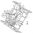
- the preferred paving vehicle 1 includes a tractor 4 and a screed 5 towed from the rear end 4b of the tractor 4.
- the tractor 4 includes a body or frame 6, a hopper 7 disposed at the tractor front end 4a and an auger 8 connected with the rear end 4b of the tractor 4.
- a conveyor (not shown) transports paving material M from the hopper 7 to the rear end 4b of the tractor 4, where the material M falls from the conveyor and deposits onto the ground or base surface B s and is spread by the auger 8 so as to accumulate in a material head M H forwardly of the screed 5.
- fumes G f from the paving material M tend to accumulate within the frame 6 at the rear end 4b of the tractor 4.
- the material fumes G f may also accumulate within the hopper 7.
- the fume removal or evacuation system 2 is configured to remove such material fumes G f and preferably includes a gas pump 39, preferably a fan or blower 40, and first and second line portions 42, 44, respectively, connected with the blower 40.
- the first line portion 42 has an inlet 46 disposed at a location L 1 at the vehicle rear end 4b where the fumes G f tend to accumulate and an outlet 48 connected with the blower 40.
- the second line portion 44 has an inlet 50 connected with the blower 40 and an outlet 52 connected with the first inlet 18 of the gas discharge device 10.
- the fume removal system 2 may alternatively include one or more other line portions (none shown) each having an inlet disposed at another location within the vehicle 1, such as location L 2 within the hopper 7, and an outlet connected with the first line portion 42 or directly with the blower 40.
- the,blower 40 causes the gas fumes G f and quantities of surrounding air A to be drawn into the inlet 50, thereby evacuating the fumes G f from the location L 1 (and possibly L 2 ), and pressurizes the fume/air mixture forming the first gas G 1 .
- the first gas flow F 1 passes through the evacuation system outlet 52 and into the discharge device first inlet 18 at a pressure substantially above ambient air pressure and generally at the first temperature - T 1 , which is preferably lesser than the temperature of the fumes G f "flowing off" of the relatively hot paving material M.
- the engine flow line 3a preferably includes a tubular member or pipe 54 having an inlet 56 connected with the engine 3 and an outlet 58 connected with the second inlet 20 of the discharge device 10.
- the engine 3 "injects" a relatively high pressure flow of exhaust gases G 2 into the discharge device 10, the second gas G 2 having pressure pulsation at a substantial, relatively high first magnitude.
- the periodic opening and closing of the exhaust valves (not shown) of an engine 3 cause exhaust gases G 2 to propagate through the pipe 54 in a pulsating, wave-like gas flow F 2 of alternating higher pressure flow portions and lower pressure flow portions (not depicted), the magnitude or amplitude of the pressure pulsation being the average pressure difference between these higher and lower pressure flow portions.
- the magnitude/amplitude of the pressure pulsation of the gas flow F 2 determines the loudness of the sound generated when the gas G 2 flows into ambient air A; more specifically, the greater the magnitude/amplitude of pressure pulsation, the greater the sound generated thereby, and vice-versa.
- the discharge device 10 functions to reduce the magnitude of pressure pulsation of the second gas G 2 prior to discharge (i.e., as part of the combined gas G c ) to ambient air A, so as to reduce the sound level that would otherwise be generated thereby.
- the gas discharge device 10 is used, according to the present invention, to combine and discharge a first gas G 1 consisting of paving material fumes and air and a second gas G 2 consisting of exhaust gases, the discharge device 10 may be used to discharge additional gas flows from the vehicle 1.
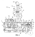
- the discharge device body 12 is preferably connectable with an upper wall 6a of the tractor frame 6 such that the two inlets 18 and 20 are disposed within the interior 6b of the frame 6 and the outlet 22 is spaced vertically above, preferably by a substantial distance (not indicated), the upper wall 6a.
- the discharge device 10 further includes a generally rectangular mounting plate 60 disposed about the first tubular portion 14 of the body 12 and having a central opening 62 through which extends the first, outer tubular portion or member 14.
- the mounting plate 60 is attached to the upper, horizontal frame wall 6a by appropriate means, such as by threaded fasteners, rivets or weldment material, to connect the discharge body 12 with the vehicle 1.
- the body 12 is preferably connected with the upper horizontal wall 6a by the mounting plate 60, the body 12 may be connected with the frame 6 by any other appropriate means, such as by a circular flange or by merely being disposed through a frame opening so as to be retained by a friction or interference fit, and/or may be mounted to any other appropriate location on the vehicle 1, such as for example, extending from a side or rear vertical frame wall (neither shown).
- the discharge body 12 preferably has a central, generally vertical axis 13, the outlet being spaced apart from each of the two inlets 18 and 20, preferably by a substantial distance (not indicated), along the vertical axis 13. Furthermore, a generally horizontal bend or hinge axis 15 extends generally perpendicularly with respect to the vertical axis 13 and is located between the outlet 22 and the two inlets 18 and 20. The body 12 is configured to bend about the hinge axis 15 such that the outlet 22 is movable in directions generally toward and away from the upper wall 6a, and thus the two inlets 18 and 20, which enables the overall height of the discharge device 10 to be reduced when the paving vehicle 1 is transported between job sites.
- the body 12 is formed of a first or lower body portion 12a connected with the vehicle 1, a second or upper body portion 12b and a hinge 64 disposed between and pivotally or “hingedly” connecting the upper and lower body portions 12a, 12b, respectively.
- the body 12 may be formed of a plurality of overlapping sections or segments or fabricated of a flexible material, so that the body 12 is bendable about the horizontal axis 15, as discussed above.
- the body 12 may be appropriately formed so as to be generally rigid or unbendable, if desired.
- the elongated body 12 most preferably includes each one of the first, outer tubular member 14 and the second, inner tubular member 16 (as discussed above) being formed of lower and upper tube halves 66, 68 and 70, 72, respectively.
- the outer tubular portion or member 14 is preferably generally circular, i.e., has generally circular cross-sections in planes extending perpendicular to the central axis 13 (see Fig. 6 ), and includes the lower tube half 66 and the upper tube half 68.
- the lower tube half 66 is attached to the tractor frame upper wall 6a by the mounting plate 60 and has a curved lower portion 67 terminating in an outer open tube end 66a, which provides the first inlet 18, and an assembly opening 69 through which extends the second member 16, as described below.
- the lower tube half 66 further has an inner open end 66b about which is disposed a first member 65A ( Fig. 2 ) of the hinge 64, as discussed in further detail below.
- the upper tube half 68 has an inner open tube end 68b disposed proximal to the lower tube half inner end 66b and about which is disposed a second hinge member 65B ( Fig. 2 ), as discussed below.
- the upper tube half 68 also has an upper curved portion 71 which terminates in an outer open tube end 68a, which provides the device outlet 22, and is configured to direct the combined gas flow F c forwardly with respect to the tractor 4, and therefore away from the screed 5 and the operator station (not indicated) where the human paver operators are located during a paving operation.
- the inner tubular portion or member 16 is preferably generally circular, i.e., has generally circular cross-sections in planes extending perpendicular to the central axis 13 (see Fig. 6 ), and includes the lower tube half 70 and the upper tube half 72.
- the lower tube half 70 extends through the assembly opening 69 of the first tubular member 16 such that the two lower tube portions 66, 70 are generally coaxially disposed about the central axis 13 of the body 12.
- the lower tube half 70 has a curved lower portion 73 terminating in an outer open tube end 70a, which provides the second inlet 20, and an inner open tube end 70b disposed within the inner tube end 66b of the first member lower tube half 66.
- the upper tube half 72 has an inner open tube end 72b disposed within the inner tube end 68b of the first member upper tube half 68 and proximal to the lower tube half inner end 70b. Also, the upper tube half 72 has an outer closed tube end 72a, specifically enclosed by a radially-extending circular end plate or cap 76 disposed within the tube end 72b, which is configured to redirect or "deflect" a portion of the second gas flow F 2 in a downward direction back along the central axis 13, as discussed in further detail below.
- the second or inner tubular member 16 is sized to have an outside diameter Do that is substantially lesser than an inside diameter D I of the first, outer tubular member 14.
- the mixing chamber 24 is provided by an annular portion of the interior space 23 extending axially along the upper portion of the second member 16 where the injection ports 36 are located.
- the axial length (not indicated) of the inner tubular member 16 is lesser than the axial length of the outer tubular member 14, such that the upper end 72a of the inner tubular member 16 is located at or below the lower end 71a of the upper curved portion 71 of the outer tubular member 14.
- the injection ports 36 of the second tubular member 16 are preferably spaced apart from each other port 36 both axially along and radially about the second member central axis 16a, and thus also the collinear body central axis 13.
- the plurality of injection ports 36 are arranged along a pair of spiral lines (not indicated) that extend in a double helix pattern about and along the axis 13.
- Such - arrangement of the injection ports 36 is intended to promote turbulence within the mixing chamber 24 since the port arrangement results in separate portions fp of the second gas flow F 2 being injected into the first gas flow F 1 at various spaced apart locations, for reasons discussed in detail below.
- the injection ports 36 may be arranged in the second tubular member 16 in any appropriate manner, such as for example in a plurality of axial lines and/or circumferential rows, since any separation or dissection of the second gas flow F 2 into separate flow portions f P will generate at least some gas turbulence within the mixing chamber 24 for reducing pressure pulsation within the combined gas flow F c , as discussed in further detail below.
- the first and second hinge members 65A, 65B, respectively, of the hinge 64 are each preferably formed as a generally rectangular plate 77 having a central opening 79.
- the lower plate 77 has a pair of spaced apart cylindrical bearing portions 81 along one edge 77a and the upper plate has a single, centrally located bearing portion 81 along a proximal edge 77a and disposed between the two bearings of the lower plate.
- the hinge 64 preferably further includes a pin 83 extending the three bearing portions 81 so as to pivotally connect the upper and lower hinge plates 77, and thereby the upper and lower body halves 12a, 12b of the discharge body 12.
- a spring 85 is preferably disposed about the pin 83 and/or bearings 81 so as to bias the two body halves toward a first, operational position (as depicted in the drawing figures).
- the hinge 64 is configured to enable the body to be foldable or pivotable about the hinge axis 15 so that the upper body half 12b is rotatably displaceable to a travel position, at which the upper body half 12b extends along the lower body half 12a and the outlet 22 is disposed proximal to the frame upper wall 6a.
- the hinge 64 may be constructed in any appropriate manner, or the body 12 may be formed without any hinge, as discussed above, as the scope of the present invention is in no manner limited by the hinge 64.
- the discharge body 12 preferably further includes three spacers or centralizers 75 (only two shown) each disposed about the second tubular member 16 and extending between the second member outer surface 34 and the first member inner surface 26.
- the three centralizers 75 are configured to position the second member 16 coaxially within the first tubular member 14 and centered about the body central axis 13.
- the centralizers 75 are constructed such that the first gas flow F 1 are and/or the combined gas flow F c is able to flow through the centralizers 75 without any significant flow interference or impedance.
- Examples of such centralizer structures include a plate with a plurality of openings or a pair of inner and outer rings with a plurality of spokes extending therebetween (neither structure shown).
- a first centralizer 75 is disposed about the lower tube half 70 proximal to the inner tube end 70b, such that the lower tube half 70 is coaxially positioned by both the first centralizer 75 and the assembly opening 69.
- a second centralizer (not shown) is disposed proximal to the inner tube end 72b of the upper tube half 72 (i.e. within the upper hinge member 65B) and a third centralizer 75 is disposed proximal to the outer tube end 72a, the upper tube half 72 thereby being coaxially positioned by these two centralizers 75.
- the elongated discharge body 12 is preferably formed as described above, the body 12 may be formed in any other appropriate manner that enables the two gases G 1 and G 2 , or gas flows F 1 and F 2 , to combine and reduce pressure pulsation of one of the gases/gas flows (i.e., of second gas G 2 ) as discussed above and in further detail below, within the scope of the present invention as defined by the appended claims.
- the two tubular portions/members 14 and 16 may be formed with ovular, rectangular or complex-shaped cross-sections, may be arranged such that the inner member 16 is disposed toward one side of the axis 13 rather than coaxial with the outer tubular member 14, and/or may be constructed as one-piece members (i.e., as opposed to upper and lower portions) (none shown).
- the body 12 may include one or more other inlets fluidly connected with the outer tubular member 14 and/or one or more other inner tubular members disposed within the outer tubular member 14 and formed generally similar to the inner tubular member 16, with each additional inlet of the outer tube 14 or the inlet of each additional inner tubular member being fluidly connectable with another source of gas/gas flow (not shown).
- the discharge device 10 may alternatively combine and discharge three or more separate gases or gas flows, while functioning to reduce the pressure pulsation magnitude of at least one of these gases.
- the scope of the present invention encompasses these and all other appropriate structures of the discharge body 12 that enables the discharge device 10 to function generally as described herein.
- the gas discharge device 10 of the present invention basically functions in the following manner.
- the material fumes/air G 1 forming the first gas flow F 1 enter the first inlet 18 and flow axially upwardly through the lower portion of the interior space 23 between the first member inner surface 26 and the second member outer surface 34, then enters the interior space upper portion providing the mixing chamber 24.
- the engine exhaust gas G 2 forming the second gas flow F 2 enters the inner tubular member 16 through the second inlet 20, flows axially upwardly along the central axis 13 and enters the interior transition chamber 32.
- the second gas flow F 2 enters the interior chamber 32 at a generally higher pressure than the first gas flow F 1 flowing through the mixing chamber 24, such that the second gas G 2 /gas flow F 2 is subsequently "injected” into the first gas G 1 /gas flow F 1 within the mixing chamber 24.
- a plurality of separate flow portions f P of the second gas flow F 2 each pass forcefully through a separate one of the injection ports 36 and combine with the first gas flow F 1 at a plurality of different locations within the mixing chamber 24.
- the second gas flow portions f p are directed by the injection ports 36 to flow generally radially outwardly (i.e., away from the axis 13) into the mixing chamber 24 such that the second gas flow F 2 "collides" with the axially upwardly flowing first gas flow F 1 in the manner of a cross-flow.
- Such turbulence promotes destructive interference between the pressure pulsations of various portions of the combined gas flow F c , i.e., portions of the combined gas G c at various locations within the mixing chamber 24, which thereby results in the combined gas G c /gas flow F c having a net level or magnitude of pressure pulsation that is lesser or reduced in comparison with the pressure pulsation magnitude of the second gas G 2 /gas flow F 2 when it enters the inner tubular member 16.
- the magnitude of pressure pulsation within the second gas flow F 2 is reduced from the pulsation magnitude at the second inlet 20, prior to combining with the first gas flow F 1 , by the following effect caused by the flow pattern of the second gas flow F 2 .
- certain portions f d of the second gas flow F 2 initially flow by (i.e., without entering) all of the ports 36, and then contact and deflect back off of the end cap 76.
- deflected flow portions f d subsequently flow axially downwardly to collide "head on” with the main portion of the second gas flow F 2 flowing axially upwardly, thereby generating destructive interfering turbulence within the second gas flow F 2 itself.
- the structure of the discharge body 12, specifically having the ported inner tubular member 16 disposed within the outer tubular member 14, also provides reduction or attenuation of the pressure pulsation magnitude of the second gas G 2 due to the mixing chamber 24 also functioning as a reactive expansion or resonator chamber, in a manner generally known in the art of muffler or silencer devices.
- the combined gas G c /gas flow F c exits the discharge device 10 through the outlet 22 so as to be discharged into ambient air A. Due to the effects described above, the combined gas G c has a pressure pulsation magnitude that is substantially lesser than the pressure pulsation magnitude of the second gas G 2 entering the device 10, such that the discharge device 10 provides the benefit of generating a lesser sound level compared to the sound level resulting were the exhaust gases G 2 discharged from the pipe 54 directly to ambient air A.
- the discharge device 10 also provides the benefit of reducing thermal energy output or "thermal pollution” compared to directly discharging the exhaust gases G 2 from the exhaust pipe 54 or even through known muffler/silencer devices (none shown). Further, the gas discharge device 10 of the present invention enables two different gases G 1 and G 2 to be discharged from the paving vehicle 1 from a single "stack" as opposed to multiple stacks as would otherwise be required, thereby reducing the number of vehicle components. In a preferred embodiment, by having a foldable body 12, the single discharge device 10 may be readily and conveniently arranged in a travel (i.e., folded) position during transportation of the vehicle 1 between different job sites.
Landscapes
- Engineering & Computer Science (AREA)
- Chemical & Material Sciences (AREA)
- Combustion & Propulsion (AREA)
- Mechanical Engineering (AREA)
- General Engineering & Computer Science (AREA)
- Architecture (AREA)
- Civil Engineering (AREA)
- Structural Engineering (AREA)
- Road Paving Machines (AREA)
Claims (13)
- Straßenbaumaschine (1), mit
einem Rauchentfernungssystem (2), das konfiguriert ist, Rauch von Straßenbaumaterial (Gf) von einer Stelle innerhalb und/oder nahe der Straßenbaumaschine (1) abzusaugen, wobei das Rauchentfernungssystem (2) einen Auslassteil (52) hat, der eine erste Gasquelle (S1) vorsieht, die ein erstes Gas (G1) ausstößt, das die Rauche des Straßenbaumaterials (Gf) und Luft enthält,
einem Motor (3), der eine Abgasströmungsleitung (3a) hat, die eine zweite Gasquelle (S2) vorsieht, die ein zweites Gas (G2) ausstößt, das Motorabgase enthält, wobei das zweite Gas (G2) eine Druckschwankung mit einer ersten Magnitude hat, und
eine Gasablassvorrichtung (10), die angepasst ist, das erste und zweite Gas (G1, G2) an die Umgebungsluft abzulassen, wobei die Gasablassvorrichtung (10) einen länglichen Körper (12), der mit der Straßenbaumaschine (1) verbunden ist und einen ersten Einlass (18), der in Fluidverbindung mit der ersten Gasquelle (S1) steht, und einen zweiten Einlass (20) hat, der in Fluidverbindung mit der zweiten Gasquelle (S2) steht, einen Auslass (22), der mit der Umgebungsluft in Fluidverbindung stehen kann, und eine innere Mischkammer (24) aufweist,
wobei der erste und zweite Einlass (18, 20) so mit der Mischkammer (24) in Fluidverbindung stehen, dass das erste und zweite Gas (G1, G2) getrennt in die Mischkammer (24) strömen können, wobei der längliche Körper (12) so konfiguriert ist, dass er das erste und zweite Gas (G1, G2) innerhalb der Mischkammer (24) zusammenführt, um ein kombiniertes Gas (Gc) zu bilden, das eine Druckschwankung mit einer zweiten Magnitude hat, wobei die zweite Schwankungsmagnitude wesentlich kleiner als die erste Schwankungsmagnitude ist, und dass er das kombinierte Gas (Gc) aus der Mischkammer (24) durch den Auslass (22) an die Umgebungsluft abgelässt,
dadurch gekennzeichnet, dass
der längliche Körper (12) weiter enthält
einen ersten rohrförmigen Teil (14), der den ersten Einlass (18) und den Auslass (22) enthält, und
einen zweiten rohrförmigen Teil (16), der zumindest teilweise innerhalb des ersten rohrförmigen Teils angeordnet ist, so dass die Mischkammer (24) zwischen dem ersten und zweiten rohrförmigen Teil (14, 16) definiert ist, wobei der zweite rohrförmige Teil (16) den zweiten Einlass (20), eine innere Kammer (32) und eine Mehrzahl von Öffnungen (36) enthält, die sich zwischen der inneren Kammer (32) und der Mischkammer (24) erstrecken. - Straßenbaumaschine (1) nach Anspruch 1 bei der die erste Gasquelle (S1) das erste Gas (G1) mit einem Druck, der im Wesentlichen größer als der Umgebungsluftdruck ist, bereit stellt.
- Straßenbaumaschine (1) nach Anspruch 1 oder 2, bei der der längliche Körper (12) konfiguriert ist, das erste und zweite Gas (G1, G2) zu kombinieren, so dass die zweite Schwankungsmagnitude in etwa Null ist und das kombinierte Gas (Gc) einen generellen konstanten Druck hat.
- Straßenbaumaschine (1) nach einem der vorhergehenden Ansprüche, bei der der längliche Körper (12) konfiguriert ist, das erste und zweite Gas (G1, D2) zu kombinieren, so dass, wenn das erste Gas (G1) generell eine erste Temperatur hat und das zweite Gas (G2) generell eine zweite Temperatur hat, wobei die zweite Temperatur wesentlich größer als die erste Temperatur ist, das kombinierte Gas (Gc) generell eine dritte Temperatur hat, wobei die dritte Temperatur wesentlich kleiner als die zweite Temperatur ist.
- Straßenbaumaschine (1) nach einem der vorhergehenden Ansprüche, bei der
der erste rohrförmige Teil eine innere Oberfläche (26) enthält, die einen inneren Raum (23) umgrenzt, und
der zweite rohrförmige Teil (16) eine äußere Oberfläche (34) enthält, wobei die äußere Oberfläche von der inneren Oberfläche des ersten rohrförmigen Teils (14) beabstandet ist und ihr generell gegenüber liegt, so dass ein Teil des inneren Raums zwischen der inneren Oberfläche des ersten rohrförmigen Teils und der äußeren Oberfläche des zweiten rohrförmigen Teils (16) die Mischkammer (24) bildet, und
der zweite rohrförmige Teil (16) auch eine innere Oberfläche (30) enthält, die die innere Kammer (32) umgrenzt, wobei sich jede Öffnung (36) zwischen der inneren und äußeren Oberfläche des zweiten rohrförmigen Teils (16) erstreckt. - Straßenbaumaschine (1) nach einem der vorhergehenden Ansprüche, bei der der zweite rohrförmige Teil (16) eine längliche Mittelachse (16a) hat und die Öffnungen (36) in Bezug auf die längliche Mittelachse (16a) axial und radial beabstandet sind.
- Straßenbaumaschine (1) nach einem der vorhergehenden Ansprüche, bei der der zweite rohrförmige Teil (16) ein erstes Ende (70a) mit einer Öffnung, die den zweiten Einlass (20) vorsieht, und ein gegenüber liegendes geschlossenes zweites Ende (72a) hat, wobei die Öffnungen (36) generell zwischen den ersten und zweiten Enden angeordnet sind.
- Straßenbaumaschine (1) nach einem der vorhergehenden Ansprüche, bei der der erste und der zweite rohrförmige Teil (14, 16) jeweils eine längliche Mittelachse (14a, 16a) haben, wobei die zwei Achsen generell kollinear sind, und generell kreisförmige Querschnitte innerhalb von Ebenen haben, die sich senkrecht in Bezug auf die kollinearen Achsen erstrecken, so dass die Mischkammer (24) generell ringförmig ist.
- Straßenbaumaschine (1) nach einem der vorhergehenden Ansprüche, bei der
der erste rohrförmige Teil (14) einen unteren Abschnitt (66), der den ersten Einlass (18) vorsieht, und einen oberen Abschnitt (68) enthält, der schwenkbar mit dem unteren Abschnitt (66) verbunden ist und den Auslass (22) vorsieht, und
der zweite rohrförmige Teil (16) einen unteren Abschnitt (70), der zumindest teilweise innerhalb des unteren Abschnitts (66) des ersten rohrförmigen Teils angeordnet ist, wobei der untere Abschnitt (70) des zweiten rohrförmigen Teils den zweiten Einlass (20) vorsieht, und einen oberen Abschnitt (72) enthält, der schwenkbar mit dem unteren Abschnitt (70) des zweiten rohrförmigen Teils verbunden ist und innerhalb des oberen Abschnitts (68) des ersten rohrförmigen Teils angeordnet ist. - Straßenbaumaschine (1) nach einem der vorhergehenden Ansprüche, bei der ein unterer Teil (12a) des länglichen Körpers (12) mit der Straßenbaumaschine verbunden ist und den ersten und zweiten Einlass (18, 20) enthält, ein oberer Teil (12b) des länglichen Körpers (12) den Auslass (22) enthält und ein Gelenk (64) dazwischen angeordnet ist und schwenkbar den oberen und unteren Körperteil (12a, 12b) verbindet.
- Straßenbaumaschine (1) nach einem der vorhergehenden Ansprüche, bei der der längliche Körper (12) eine mittlere, generell vertikale Achse (13) aufweist, wobei der Auslass (22) vertikal beabstandet von jedem des ersten und zweiten Einlasses (18, 20) entlang der vertikalen Achse (13) ist, und eine generell horizontale Achse (15) aufweist, die sich generell senkrecht in Bezug auf die vertikale Achse (13) erstreckt und zwischen dem Auslass (22) und dem ersten und zweiten Einlasse (18, 20) angeordnet ist, wobei der längliche Körper (12) dazu konfiguriert ist, sich so um die horizontale Achse (15) zu beugen, dass der Auslass (22) alternativ hin und weg von dem ersten und zweiten Einlass (18, 20) bewegbar ist.
- Straßenbaumaschine (1) nach Anspruch 6 oder 7, bei der die Öffnungen (36) sich durch den zweiten rohrförmigen Teil (12) erstrecken und in einem generell schraubenförmigen Muster in Bezug auf die längliche Mittelachse (16a) des zweiten rohrförmigen Teils (16) angeordnet sind.
- Straßenbaumaschine (1) nach Anspruch 12, bei der die Straßenbaumaschine einen Körper (6) mit einer oberen Fläche (6a) hat und der erste rohrförmige Teil (14) sich so durch den Körper erstreckt, dass der Auslass (22) vertikal oberhalb der oberen Fläche des Körpers beabstandet ist.
Applications Claiming Priority (3)
| Application Number | Priority Date | Filing Date | Title |
|---|---|---|---|
| US293135 | 1999-04-16 | ||
| US10/293,135 US6832872B2 (en) | 2002-11-13 | 2002-11-13 | Gas discharge device for a construction vehicle |
| PCT/US2003/036014 WO2004044331A1 (en) | 2002-11-13 | 2003-11-12 | Gas discharge device for a construction vehicle |
Publications (2)
| Publication Number | Publication Date |
|---|---|
| EP1573135A1 EP1573135A1 (de) | 2005-09-14 |
| EP1573135B1 true EP1573135B1 (de) | 2012-12-26 |
Family
ID=32229609
Family Applications (1)
| Application Number | Title | Priority Date | Filing Date |
|---|---|---|---|
| EP03768881A Expired - Lifetime EP1573135B1 (de) | 2002-11-13 | 2003-11-12 | Strassenbaumaschine mit Abgasvorrichtung |
Country Status (6)
| Country | Link |
|---|---|
| US (1) | US6832872B2 (de) |
| EP (1) | EP1573135B1 (de) |
| CN (1) | CN100564822C (de) |
| AU (1) | AU2003291479A1 (de) |
| RU (1) | RU2333307C2 (de) |
| WO (1) | WO2004044331A1 (de) |
Families Citing this family (40)
| Publication number | Priority date | Publication date | Assignee | Title |
|---|---|---|---|---|
| SE525066C2 (sv) * | 2003-04-16 | 2004-11-23 | Volvo Constr Equip Holding Se | Förfarande för ventilering av en arbetsmaskin, och en sådan arbetsmaskin |
| KR100638204B1 (ko) * | 2004-12-10 | 2006-10-26 | 엘지전자 주식회사 | 엔진의 배기가스 배출구조 |
| SE529187C2 (sv) * | 2005-10-10 | 2007-05-22 | Ilmeg Products Ab | System och förfarande för rening av asfaltgas |
| GB2447401B (en) * | 2005-12-19 | 2011-05-11 | L C Eldridge Sales Co Ltd | Method and apparatus for manipulating and diluting internal combustion exhaust gases |
| US7669411B2 (en) * | 2006-05-10 | 2010-03-02 | Caterpillar Inc. | Cooling device |
| DE202007003326U1 (de) * | 2007-03-06 | 2007-04-26 | Joseph Voegele Ag | Straßenfertiger |
| US7931104B2 (en) * | 2007-08-28 | 2011-04-26 | Caterpillar Paving Products Inc. | Machine having cooling system and method |
| US7785034B2 (en) * | 2008-06-26 | 2010-08-31 | Weiler, Inc. | Desegregation system |
| DE102008064017A1 (de) * | 2008-12-19 | 2010-06-24 | Daimler Ag | Abgasanlage für eine Brennkraftmaschine |
| KR101026190B1 (ko) * | 2009-01-23 | 2011-03-31 | 볼보 컨스트럭션 이큅먼트 에이비 | 엔진룸의 과열가스 온도 저감장치 |
| JP5678415B2 (ja) * | 2009-07-21 | 2015-03-04 | 株式会社リコー | 情報処理装置、情報処理装置利用システム、処理条件編集方法 |
| US20110048847A1 (en) * | 2009-09-02 | 2011-03-03 | United States Of America As Represented By The Secretary Of The Navy | Noise attenuation device for reducing noise attenuation in a jet engine test cell |
| US8869516B2 (en) | 2010-11-03 | 2014-10-28 | Caterpillar Sarl | Method of mixing exhaust gas exiting an exhaust stack outlet with cooling air exiting a cooling package outlet and machine using same |
| US8479498B2 (en) | 2010-11-03 | 2013-07-09 | Caterpillar Sarl | Method of mixing exhaust gas exiting an exhaust stack outlet with cooling air exiting a cooling package outlet including a regeneration control algorithm and machine using same |
| US8556014B2 (en) | 2010-11-03 | 2013-10-15 | Caterpillar Inc. | Diesel particulate filter packaging and method of directing airflow in a skid steer machine |
| USD655317S1 (en) * | 2011-05-10 | 2012-03-06 | Cnh America Llc | Tractor hood |
| JP5886551B2 (ja) * | 2011-07-19 | 2016-03-16 | コベルコ建機株式会社 | 建設機械の排気構造 |
| JP5886552B2 (ja) * | 2011-07-19 | 2016-03-16 | コベルコ建機株式会社 | 建設機械の排気構造 |
| USD693749S1 (en) * | 2011-08-01 | 2013-11-19 | Joseph Vögele AG | Extension arm with light and mirror for a road construction machine |
| DE102011087675A1 (de) * | 2011-12-02 | 2013-06-06 | Deere & Company | Kühlsystem zur aktiven Kühlung eines Abgassystems |
| USD668691S1 (en) * | 2012-02-01 | 2012-10-09 | Joseph Vögele AG | Cover for an exhaust port of a road construction machine |
| DE102012025620A1 (de) | 2012-03-06 | 2023-03-30 | Abg Allgemeine Baumaschinen-Gesellschaft Mbh | Straßenfertiger |
| DE202012002966U1 (de) | 2012-03-06 | 2012-04-10 | Abg Allgemeine Baumaschinen-Gesellschaft Mbh | Straßenfertiger |
| DE102012025589A1 (de) | 2012-03-06 | 2013-09-12 | Abg Allgemeine Baumaschinen-Gesellschaft Mbh | Straßenfertiger |
| EP2672008B1 (de) * | 2012-06-05 | 2018-01-10 | Joseph Vögele AG | Straßenfertiger und Verfahren zum Einbauen von Mischgut mit einem Straßenfertiger |
| DE102012011693B4 (de) | 2012-06-12 | 2014-03-13 | Abg Allgemeine Baumaschinen-Gesellschaft Mbh | Straßenfertiger |
| USD698831S1 (en) * | 2012-10-09 | 2014-02-04 | Cnh America Llc | Combined tractor windows and intake and exhaust |
| USD687075S1 (en) * | 2012-12-18 | 2013-07-30 | Cnh America Llc | Intake system for an agricultural work vehicle |
| US20140216007A1 (en) * | 2013-04-15 | 2014-08-07 | Søren B. Olsen | Device and method for an exhaust system of a motor vehicle |
| JP5812038B2 (ja) * | 2013-04-19 | 2015-11-11 | コベルコ建機株式会社 | 建設機械の排気構造 |
| US20140360159A1 (en) * | 2013-06-06 | 2014-12-11 | Deere & Company | Precipitation cover for an exhaust system |
| JP5673775B1 (ja) * | 2013-10-25 | 2015-02-18 | 井関農機株式会社 | 作業車両 |
| JP6000931B2 (ja) * | 2013-11-18 | 2016-10-05 | 株式会社クボタ | 作業車両 |
| US9068296B1 (en) * | 2014-03-14 | 2015-06-30 | SuperiorRoads Solutions Limited Partnership | Thermostatically controlled asphalt heater for a mobile pavement patching vehicle |
| US20150377192A1 (en) * | 2014-06-30 | 2015-12-31 | Caterpillar Inc. | Exhaust ejector tube for engine system |
| CN106795791B (zh) | 2014-08-08 | 2022-04-26 | 卡明斯公司 | 强制排气扩散器 |
| US9556790B2 (en) * | 2015-02-12 | 2017-01-31 | Deere & Company | Bi-directional tractor exhaust system with ground speed detection |
| CN105089705B (zh) * | 2015-09-11 | 2018-03-06 | 山东科灵节能装备股份有限公司 | 静涡盘及涡旋膨胀机及发电机组 |
| KR101894343B1 (ko) * | 2016-05-24 | 2018-09-03 | 가부시키가이샤 고마쓰 세이사쿠쇼 | 작업 차량 |
| US12320416B2 (en) * | 2021-05-07 | 2025-06-03 | Kawasaki Motors, Ltd. | Utility vehicle |
Family Cites Families (24)
| Publication number | Priority date | Publication date | Assignee | Title |
|---|---|---|---|---|
| US2501767A (en) | 1948-03-01 | 1950-03-28 | Fluor Corp | Muffler with internal side branch chamber |
| US2725948A (en) * | 1951-05-14 | 1955-12-06 | Charles I Keene | Vertical muffler for internal combustion engine |
| US3106984A (en) | 1962-01-09 | 1963-10-15 | Laclede Metal Products Co | Muffler construction |
| US3804079A (en) * | 1971-06-01 | 1974-04-16 | Cleasby Mfg Co Inc | Melting kettle and apparatus and method for eliminating objectionable emissions therefrom |
| US4012160A (en) * | 1974-03-18 | 1977-03-15 | Parker Jimmy L | Paving machine with enclosed material compartment |
| US4033328A (en) * | 1975-11-26 | 1977-07-05 | Blackwell Burner Company | Tar melting kettle |
| FR2345586A1 (fr) | 1976-03-24 | 1977-10-21 | Nihon Radiator Co | Pot d'echappement |
| CH647302A5 (de) | 1979-06-06 | 1985-01-15 | Alusuisse | Vorrichtung zum ableiten der abgase von verbrennungskraftmaschinen. |
| US4401095A (en) | 1981-02-24 | 1983-08-30 | Taylor C. Miller, Jr. | Fuel-air mixing device |
| US4388804A (en) | 1981-08-17 | 1983-06-21 | J. I. Case Company | Exhaust assembly for tractors |
| US5123501A (en) | 1988-10-21 | 1992-06-23 | Donaldson Company, Inc. | In-line constricted sound-attenuating system |
| US5058704A (en) * | 1988-11-21 | 1991-10-22 | Yu Chuen Huan | Turbo jet muffler |
| US5170020A (en) | 1991-03-05 | 1992-12-08 | Deere & Company | Rainproof exhaust pipe |
| RU2005836C1 (ru) * | 1991-10-17 | 1994-01-15 | Николаевский завод "Дормашина" им.50-летия Великого Октября | Асфальтоукладчик |
| US5328209A (en) * | 1993-07-20 | 1994-07-12 | Cromwell Steve D | Vehicle exhaust stack joint yieldable in all directions |
| US5443325A (en) * | 1994-02-04 | 1995-08-22 | Blaw-Knox Construction Equipment Corporation | Asphalt fume reduction system |
| US5890460A (en) | 1995-05-08 | 1999-04-06 | Ball; Ronald C. | Electrical generator set |
| US5951725A (en) * | 1995-06-07 | 1999-09-14 | National Tool And Equipment, Inc. | System for removal of noxious fumes |
| DE29510058U1 (de) * | 1995-06-21 | 1995-11-02 | Joseph Vögele AG, 68163 Mannheim | Deckenfertiger |
| US6079901A (en) | 1997-08-12 | 2000-06-27 | Midland Machinery Co., Inc | Paving machine capable of spraying a liquid binding material |
| US5938371A (en) | 1997-09-16 | 1999-08-17 | Caterpillar Paving Products | Fumes abatement system for an asphalt paving machine |
| US6152649A (en) * | 1998-08-27 | 2000-11-28 | Blaw-Know Construction Equipment Corp. | Fumes collection for an auger-type distributing device on an asphalt paver |
| US6220387B1 (en) * | 1999-10-21 | 2001-04-24 | Mathew S. Hoppes | Exhaust muffler |
| DE10200361B4 (de) | 2002-01-08 | 2013-09-12 | Hermann Kirchner Gmbh & Co Kg | Straßenfertiger zum entmischungsfreien Mischguteinbau |
-
2002
- 2002-11-13 US US10/293,135 patent/US6832872B2/en not_active Expired - Lifetime
-
2003
- 2003-11-12 WO PCT/US2003/036014 patent/WO2004044331A1/en not_active Ceased
- 2003-11-12 AU AU2003291479A patent/AU2003291479A1/en not_active Abandoned
- 2003-11-12 CN CN200380108234.8A patent/CN100564822C/zh not_active Expired - Fee Related
- 2003-11-12 RU RU2005118105/03A patent/RU2333307C2/ru not_active IP Right Cessation
- 2003-11-12 EP EP03768881A patent/EP1573135B1/de not_active Expired - Lifetime
Also Published As
| Publication number | Publication date |
|---|---|
| CN1735733A (zh) | 2006-02-15 |
| US20040088968A1 (en) | 2004-05-13 |
| RU2333307C2 (ru) | 2008-09-10 |
| EP1573135A1 (de) | 2005-09-14 |
| RU2005118105A (ru) | 2006-01-20 |
| AU2003291479A1 (en) | 2004-06-03 |
| US6832872B2 (en) | 2004-12-21 |
| CN100564822C (zh) | 2009-12-02 |
| WO2004044331A1 (en) | 2004-05-27 |
Similar Documents
| Publication | Publication Date | Title |
|---|---|---|
| EP1573135B1 (de) | Strassenbaumaschine mit Abgasvorrichtung | |
| US20240159178A1 (en) | System for mixing a liquid spray into a gaseous flow and exhaust aftertreatment device comprising same | |
| KR101377233B1 (ko) | 후부 배기관의 배기온도를 저감시키기 위한 장치 | |
| US8046989B2 (en) | Cooling device for high temperature exhaust | |
| US7549511B2 (en) | Exhaust sound and emission control systems | |
| CA1102708A (en) | Complete louver flow muffler | |
| US4388804A (en) | Exhaust assembly for tractors | |
| TWI247867B (en) | Gas turbine combustor, and gas turbine with the combustor | |
| US7491012B2 (en) | Road finisher | |
| EP1015739B1 (de) | Lärmdämpfungsgerät | |
| WO1999036680A1 (en) | Improved high performance muffler | |
| SE467315B (sv) | Avgasljuddaempare foer tvaataktsmotorer, i synnerhet foer baerbara arbetsredskap | |
| GB2115870A (en) | Exhaust muffler with protective shield | |
| RU2679789C1 (ru) | Отопитель транспортного средства | |
| US8136350B2 (en) | Catalytic muffler having crossover passageway for secondary air | |
| US4809502A (en) | Power equipment | |
| KR102252340B1 (ko) | 배기 가스 정화 장치 | |
| US6464036B1 (en) | Air intake silencer | |
| KR101001349B1 (ko) | 연소 기관의 배기 가스 시스템 내에 설치되는 하우징 | |
| US3298458A (en) | Exhaust pipe silencers with telescoped gas passage tubes | |
| CA2319292C (en) | An air intake silencer | |
| CN118110583A (zh) | 用于排气系统的消声器 | |
| US10001048B2 (en) | Cyclonic thermal diffuser and method | |
| GB2600783A (en) | An Exhaust System | |
| MXPA00007007A (en) | Improved high performance muffler |
Legal Events
| Date | Code | Title | Description |
|---|---|---|---|
| PUAI | Public reference made under article 153(3) epc to a published international application that has entered the european phase |
Free format text: ORIGINAL CODE: 0009012 |
|
| 17P | Request for examination filed |
Effective date: 20050610 |
|
| AK | Designated contracting states |
Kind code of ref document: A1 Designated state(s): AT BE BG CH CY CZ DE DK EE ES FI FR GB GR HU IE IT LI LU MC NL PT RO SE SI SK TR |
|
| AX | Request for extension of the european patent |
Extension state: AL LT LV MK |
|
| DAX | Request for extension of the european patent (deleted) | ||
| RBV | Designated contracting states (corrected) |
Designated state(s): DE FR GB SE |
|
| RIN1 | Information on inventor provided before grant (corrected) |
Inventor name: ROTH, THOMAS, A. Inventor name: KOELM, MARK, D. |
|
| 17Q | First examination report despatched |
Effective date: 20070801 |
|
| GRAP | Despatch of communication of intention to grant a patent |
Free format text: ORIGINAL CODE: EPIDOSNIGR1 |
|
| GRAS | Grant fee paid |
Free format text: ORIGINAL CODE: EPIDOSNIGR3 |
|
| GRAA | (expected) grant |
Free format text: ORIGINAL CODE: 0009210 |
|
| AK | Designated contracting states |
Kind code of ref document: B1 Designated state(s): DE FR GB SE |
|
| REG | Reference to a national code |
Ref country code: GB Ref legal event code: FG4D |
|
| REG | Reference to a national code |
Ref country code: DE Ref legal event code: R096 Ref document number: 60342963 Country of ref document: DE Effective date: 20130228 |
|
| REG | Reference to a national code |
Ref country code: SE Ref legal event code: TRGR |
|
| PLBE | No opposition filed within time limit |
Free format text: ORIGINAL CODE: 0009261 |
|
| STAA | Information on the status of an ep patent application or granted ep patent |
Free format text: STATUS: NO OPPOSITION FILED WITHIN TIME LIMIT |
|
| 26N | No opposition filed |
Effective date: 20130927 |
|
| REG | Reference to a national code |
Ref country code: DE Ref legal event code: R097 Ref document number: 60342963 Country of ref document: DE Effective date: 20130927 |
|
| REG | Reference to a national code |
Ref country code: FR Ref legal event code: PLFP Year of fee payment: 13 |
|
| PGFP | Annual fee paid to national office [announced via postgrant information from national office to epo] |
Ref country code: GB Payment date: 20151113 Year of fee payment: 13 Ref country code: DE Payment date: 20151110 Year of fee payment: 13 |
|
| PGFP | Annual fee paid to national office [announced via postgrant information from national office to epo] |
Ref country code: SE Payment date: 20151113 Year of fee payment: 13 Ref country code: FR Payment date: 20151127 Year of fee payment: 13 |
|
| REG | Reference to a national code |
Ref country code: DE Ref legal event code: R119 Ref document number: 60342963 Country of ref document: DE |
|
| REG | Reference to a national code |
Ref country code: SE Ref legal event code: EUG |
|
| GBPC | Gb: european patent ceased through non-payment of renewal fee |
Effective date: 20161112 |
|
| REG | Reference to a national code |
Ref country code: FR Ref legal event code: ST Effective date: 20170731 |
|
| PG25 | Lapsed in a contracting state [announced via postgrant information from national office to epo] |
Ref country code: SE Free format text: LAPSE BECAUSE OF NON-PAYMENT OF DUE FEES Effective date: 20161113 |
|
| PG25 | Lapsed in a contracting state [announced via postgrant information from national office to epo] |
Ref country code: FR Free format text: LAPSE BECAUSE OF NON-PAYMENT OF DUE FEES Effective date: 20161130 |
|
| PG25 | Lapsed in a contracting state [announced via postgrant information from national office to epo] |
Ref country code: GB Free format text: LAPSE BECAUSE OF NON-PAYMENT OF DUE FEES Effective date: 20161112 Ref country code: DE Free format text: LAPSE BECAUSE OF NON-PAYMENT OF DUE FEES Effective date: 20170601 |