EP1571392A2 - Kfz-Scheinwerfer - Google Patents
Kfz-Scheinwerfer Download PDFInfo
- Publication number
- EP1571392A2 EP1571392A2 EP05004467A EP05004467A EP1571392A2 EP 1571392 A2 EP1571392 A2 EP 1571392A2 EP 05004467 A EP05004467 A EP 05004467A EP 05004467 A EP05004467 A EP 05004467A EP 1571392 A2 EP1571392 A2 EP 1571392A2
- Authority
- EP
- European Patent Office
- Prior art keywords
- focal point
- reflecting surface
- sub
- light
- distribution pattern
- Prior art date
- Legal status (The legal status is an assumption and is not a legal conclusion. Google has not performed a legal analysis and makes no representation as to the accuracy of the status listed.)
- Granted
Links
- 230000003287 optical effect Effects 0.000 claims description 33
- BQCADISMDOOEFD-UHFFFAOYSA-N Silver Chemical compound [Ag] BQCADISMDOOEFD-UHFFFAOYSA-N 0.000 description 5
- 229910052782 aluminium Inorganic materials 0.000 description 5
- XAGFODPZIPBFFR-UHFFFAOYSA-N aluminium Chemical compound [Al] XAGFODPZIPBFFR-UHFFFAOYSA-N 0.000 description 5
- 239000011248 coating agent Substances 0.000 description 5
- 238000000576 coating method Methods 0.000 description 5
- 229910052709 silver Inorganic materials 0.000 description 5
- 239000004332 silver Substances 0.000 description 5
- 238000007740 vapor deposition Methods 0.000 description 5
- 238000000034 method Methods 0.000 description 4
- 230000000712 assembly Effects 0.000 description 2
- 238000000429 assembly Methods 0.000 description 2
- 239000003518 caustics Substances 0.000 description 1
- 238000010276 construction Methods 0.000 description 1
- 238000005516 engineering process Methods 0.000 description 1
- 229910052736 halogen Inorganic materials 0.000 description 1
- 150000002367 halogens Chemical class 0.000 description 1
- 230000001678 irradiating effect Effects 0.000 description 1
- 229910052751 metal Inorganic materials 0.000 description 1
- 239000002184 metal Substances 0.000 description 1
- 229910001507 metal halide Inorganic materials 0.000 description 1
- 150000005309 metal halides Chemical class 0.000 description 1
- 238000012986 modification Methods 0.000 description 1
- 230000004048 modification Effects 0.000 description 1
- 239000007787 solid Substances 0.000 description 1
Images



Classifications
-
- F—MECHANICAL ENGINEERING; LIGHTING; HEATING; WEAPONS; BLASTING
- F21—LIGHTING
- F21S—NON-PORTABLE LIGHTING DEVICES; SYSTEMS THEREOF; VEHICLE LIGHTING DEVICES SPECIALLY ADAPTED FOR VEHICLE EXTERIORS
- F21S41/00—Illuminating devices specially adapted for vehicle exteriors, e.g. headlamps
- F21S41/40—Illuminating devices specially adapted for vehicle exteriors, e.g. headlamps characterised by screens, non-reflecting members, light-shielding members or fixed shades
- F21S41/43—Illuminating devices specially adapted for vehicle exteriors, e.g. headlamps characterised by screens, non-reflecting members, light-shielding members or fixed shades characterised by the shape thereof
-
- F—MECHANICAL ENGINEERING; LIGHTING; HEATING; WEAPONS; BLASTING
- F21—LIGHTING
- F21S—NON-PORTABLE LIGHTING DEVICES; SYSTEMS THEREOF; VEHICLE LIGHTING DEVICES SPECIALLY ADAPTED FOR VEHICLE EXTERIORS
- F21S41/00—Illuminating devices specially adapted for vehicle exteriors, e.g. headlamps
- F21S41/30—Illuminating devices specially adapted for vehicle exteriors, e.g. headlamps characterised by reflectors
- F21S41/32—Optical layout thereof
- F21S41/36—Combinations of two or more separate reflectors
- F21S41/365—Combinations of two or more separate reflectors successively reflecting the light
Definitions
- the present invention relates to a projector-type headlamp.
- These headlamps have a light source, a main reflector and a plurality of subreflectors.
- the main reflector When the light source is turned on, the main reflector creates a main light distribution pattern, and the subreflectors effectively utilize a portion of this light, which usually results in becoming ineffective, to thereby creating a sub-light distribution pattern. In this way, the headlamps can effectively utilize the light.
- Japanese Patent No. 3488960 also discloses a technique of rotating a subreflector so as to direct the sub-light distribution pattern to the left side or the right side of the main light distribution pattern.
- this technique requires rotating the subreflector in a wide range from left to right, which lowers the efficiency.
- a projector-type headlamp includes a main reflector that includes a main reflecting surface that is substantially an ellipsoid of revolution having a first focal point and a second focal point; the light source located on or substantially close to the first focal point; a projector lens that projects outward a predetermined light distribution pattern, the projector lens having a third focal point, wherein the projector lens is arranged such that the third focal point is located on or substantially close to the second focal point; a first subreflector with a first sub-reflecting surface that is substantially an ellipsoid of revolution having a fourth focal point and a fifth focal point, wherein the first subreflector is arranged such that the fourth focal point is located on or substantially close to the first focal point, and the first sub-reflecting surface reflects a portion of light output from the light source that usually results in becoming ineffective toward the fifth focal point; a second subreflector with a second sub-reflecting surface that is substantially an ellip
- VU-VD is a vertical line passing through an optical axis Z-Z of the headlamp, as well as a vertical line on a screen.
- HL-HR is a horizontal line passing through the optical axis Z-Z, as well as a horizontal line on a screen.
- F is a front side of a vehicle C (a forward driving direction of the vehicle C).
- B is a rear side
- U is an upper side
- D is a lower side
- L is a left side of the vehicle
- R is a right side, all with respect to the driver of the vehicle.
- left outer side, right outer side, left lower side, right lower side, left side, and right side used in the claims have the meaning described above herein and in the drawings.
- a headlamp 1 includes a headlamp assembly 100L mounted on the left side and a headlamp assembly 100R mounted on the right side of the vehicle C.
- the headlamp assemblies 100L and 100R have almost the same configuration, therefore, the headlamp assemblies 100L will only be explained here.
- the headlamp assembly 100L includes a light housing 101 and an outer lens (light lens) 102 defining a light chamber (not shown), a driving headlamp unit (not shown) and a passing headlamp unit.
- a portion of the outer lens 102, other than the portions corresponding to a projector lens 103 of the driving headlamp unit, a projector lens 4 of the passing headlamp unit, and an inner lens 40 of the passing headlamp unit, is formed into a vertical prism 104 that functions as a blind on the light chamber.
- a portion of the light chamber, other the portions corresponding to the projector lens 103, the projector lens 4, and the inner lens 40, is covered with an inner panel (or an inner housing or an extension, not shown in Fig. 11) so that structure inside the light chamber is not seen from the outside.
- the headlamp 1 will be described below with reference to Figs. 1 to 10.
- the following description refers to the headlamp assembly 100L.
- the structure of the headlamp assembly 100R is generally symmetrical with that of the headlamp assembly 100L, except the configuration of some of the parts.
- the headlamp assembly 100L is of a projector type.
- the headlamp assembly 100L includes a light source (not shown), a main reflector 3, a projector lens (condenser lens) 4, a shade 5, a first subreflector 6, a second subreflector 7, a third subreflector 8, and a fourth subreflector 9.
- the light source may be a discharge light such as a high-pressure metal vapor discharge lamp including a so-called metal halide lamp, a high intensity discharge lamp (HID), or a halogen lamp.
- the light source is removably attached to the main reflector 3 via a socket mechanism (not shown).
- a center F1 of a light emitting section of the light source is located on or near a first focal point F31 of a main reflecting surface 30 of the main reflector 3.
- the center F1 and the first focal point F31 are located substantially at the same position (refer to Fig. 6).
- the inner concave surface of the main reflector 3 is finished with aluminum vapor deposition or silver coating, thus forming the main reflecting surface 30, which is substantially an ellipsoid of revolution (NURBS surface or free-form surface).
- the main reflecting surface 30 has an elliptical vertical cross-section, and a paraboloidal or a modified paraboloidal horizontal cross-section as in Fig. 5. Accordingly, the main reflecting surface 30 has the first focal point F31 and a second focal point (a caustic on the horizontal cross-section) F32.
- the main reflector 3 is fixedly held by a holder or a frame (not shown; hereinafter, simply a holder).
- the main reflecting surface 30 reflects a portion (not shown) of light from the light source, to thereby utilize the portion as a passing light distribution pattern LP. Therefore, light except the portion reflected by the main reflecting surface 30 out of the light from the light source (light L1 represented by solid arrow lines in Fig. 6, i.e. direct light irradiated upwardly forward by the light source) usually results in becoming ineffective.
- the projector lens 4 includes a non-spherical lens, a condenser lens, a convex lens and so forth.
- a front face of the projector lens 4 presents a non-spherical convex surface, while a rear face thereof presents a non-spherical plane.
- a focal point F4 of the projector lens 4 is located on or near a second focal point F32 of the main reflecting surface 30.
- a focal plane (meridional image plane) F4 on an object space side of the projector lens 4 is located ahead of the second focal point F32.
- the second focal point F32 and the focal point F4 are located substantially at the same position (refer to Fig. 6).
- the projector lens 4 is fixedly held by a holder.
- the projector lens 4 serves to outwardly project the reflected light (not shown) from the main reflecting surface 30, but excluding the portion of the reflected light (not shown) cut off by the shade 5, in the form of the passing light distribution pattern LP (refer to Figs. 9 and 10).
- the shade 5 cuts off a portion of the reflected light from the main reflecting surface 30, and utilizes the remaining reflected light to form the passing light distribution pattern LP.
- the shade 5 is provided with a wedge 50 along an upper end thereof, which serves as a cut-off line CL for the passing light distribution pattern LP.
- the wedge 50 of the shade 5 is located on or near the second focal point F32 and the focal point F4.
- the wedge 50 of the shade 5, the second focal point F32 and the focal point F4 are located substantially at the same position (refer to Fig. 6).
- the shade 5 is fixedly held by a holder.
- the passing light distribution pattern LP and the shade 5 are designed on the assumption that the vehicle C drives on the left side, and when the vehicle C drives on the right side, the configuration of the passing light distribution pattern LP and the shade 5 become generally symmetrical with that of the left-side drive.
- the first subreflector 6 is arranged between the main reflector 3 and the projector lens 4, so as to oppose an upper and lateral portion of the main reflector 3 (refer to Figs. 4 and 6).
- the inner concave surface of the first subreflector 6 is finished with aluminum vapor deposition or silver coating, thus forming a first sub-reflecting surface 60 (NURBS surface or free-form surface), which is substantially an ellipsoid of revolution (refer to an ellipsoid 61 of the double-dashed line in Fig. 6).
- a first focal point F61 of the first sub-reflecting surface 60 is located on or near the first focal point F31 (and the center F1 of the light emitting section of the light source).
- the first focal point F61 of the first sub-reflecting surface 60 and the first focal point F31 (and a central portion F1 of the light emitting section of the light source) are located substantially at the same position (refer to Fig. 6).
- the first subreflector 6 is fixedly held by a holder.
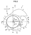
- a second focal point F62 of the first sub-reflecting surface 60 is located between the shade 5 and the projector lens 4 (refer to Figs. 4 to 6), and on a left lower side with respect to the optical axis Z-Z of the main reflecting surface 30 and the projector lens 4 (refer to Fig. 2).
- the first sub-reflecting surface 60 serves to reflect the light L1 (direct light irradiated upwardly forward by the light source), which usually results in becoming ineffective, out of the light from the light source, toward the second focal point F62 as a reflected light L2 (refer to Fig. 6).
- an obstacle such as the shade 5 is not located.
- the second subreflector 7 is located between the shade 5 and the projector lens 4, so as to oppose a lower and right side portion of the first subreflector 6 (refer to Figs. 4 and 6).
- the inner concave surface of the second subreflector 7 is finished with aluminum vapor deposition or silver coating, thus forming a second sub-reflecting surface 70 (NURBS surface or free-form surface), which is substantially an ellipsoid of revolution (refer to an ellipsoid 71 of the double-dashed line in Fig. 7).
- a first focal point F71 of the second sub-reflecting surface 70 is located on or near the second focal point F62.
- the first focal point F71 and the second focal point F62 are located substantially at the same position refer to Fig. 6).
- the second subreflector 7 is fixedly held by a holder.
- a second focal point F72 of the second sub-reflecting surface 70 is located on an outer side of the main reflecting surface 30 and the projector lens 4, the left side of the optical axis Z-Z (refer to Figs. 2 and 5).
- the second sub-reflecting surface 70 serves to reflect the reflected light L2 toward the second focal point F72 as a reflected light L3 (refer to Fig. 7).
- no obstacles exist such as the shade 5.
- the third subreflector 8 is located between the main reflector 3 and the projector lens 4, so as to oppose an outer left side portion of the second subreflector 7 (refer to Figs. 2 and 5).
- the inner concave surface of the third subreflector 8 is finished with aluminum vapor deposition or silver coating, thus forming a third sub-reflecting surface 80 (NURBS surface or free-form surface), which is substantially a paraboloid of revolution (refer to a parabola 81 in double-dashed line in Figs. 5 and 7).
- a focal point F8 of the third sub-reflecting surface 80 is located on or near the second focal point F72.
- the focal point F8 and the second focal point F72 are located substantially at the same position (refer to Figs. 5 and 7).
- the third subreflector 8 is fixedly held by a holder.
- An optical axis Z1-Z1 of the third sub-reflecting surface 80 is inclined to the left with respect to the optical axis Z-Z ((Z)-(Z) in Fig. 5), by an angle ⁇ (refer to Figs. 3 and 5).
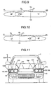
- the third sub-reflecting surface 80 serves to reflect the reflected light L3 from the second sub-reflecting surface 70, toward the outside as a reflected light L4, to a left side with respect to the passing light distribution pattern LP (refer to Fig. 7). Consequently, as shown in Fig. 9, a sub-light distribution pattern SP is directed to the left side with respect to the passing light distribution pattern LP.
- a controller such as the inner lens 40 constituted of a prism lens, that controls the reflected light L4 from the third subreflector 8 is arranged in front of the third subreflector 8.
- the angle ⁇ between the optical axis Z1-Z1 and the optical axis Z-Z is 35 degrees; however, the angle ⁇ can be set to any desirable value.
- the distance T between the focal point F8 and the ellipsoid 81 is 12 millimeters; however, the distance T can be set to any desirable value.
- the fourth subreflector 9 is located between the main reflector 3 and the first subreflector 6, and above the main reflector 3, the first subreflector 6 and the third subreflector 8 (refer to Figs. 2, 4 and 8).
- the inner concave surface of the fourth subreflector 9 is finished with aluminum vapor deposition or silver coating, thus forming a fourth sub-reflecting surface 90 (NURBS surface or free-form surface), which is substantially a paraboloid of revolution (refer to a parabola 91 in double-dashed line in Fig. 8).
- a focal point F9 of the fourth sub-reflecting surface 90 is located on or near the first focal point F31 (and the center F1 of the light emitting section of the light source and the first focal point F61 of the first sub-reflecting surface 60).
- the focal point F9, the first focal point F61 of the first sub-reflecting surface 60 and the first focal point F31 (and the center F1 of the light emitting section of the light source and the first focal point F61 of the first sub-reflecting surface) are located substantially at the same position (refer to Fig. 8).
- the fourth subreflector 9 is fixedly held by a holder.
- An optical axis (not shown) of the fourth sub-reflecting surface 90 substantially coincides with the optical axis Z-Z (refer to Fig. 8).
- the fourth sub-reflecting surface 90 serves to reflect the ineffective light L5 from the light source (direct light irradiated upwardly forward by the light source, as the ineffective light L1), toward outside as a reflected light L6, to a lower side with respect to the passing light distribution pattern LP.
- a controller that controls the reflected light L6 from the fourth sub-reflecting surface 90 is arranged, such as an inner lens constituted of a prism lens.
- the headlamp assembly 100L operates as described hereunder.
- the light source is turned on. A portion of the light from the light source is reflected by the main reflecting surface 30. The reflected light converges at the second focal point F32 and the focal point F4. A portion of the converged reflected light is cut off by the shade 5. The remaining portion of the reflected light which has not been cut off diffuses through the second focal point F32 and the focal point F4, and proceeds outward through the projector lens 4 to irradiate a forward lateral area.
- the passing light distribution pattern LP is obtained as shown in Fig. 9.
- the remaining portion of the light from the light source i.e. the light L1 which usually results in becoming ineffective without being reflected by the main reflecting surface 30 (direct light irradiated upwardly forward by the light source), being made incident upon the first sub-reflecting surface 60.
- the light L1 is made incident on the first sub-reflecting surface 60, is thereby reflected to be the reflected light L2, and converges at the second focal point F62 and the first focal point F71.
- the converged reflected light L2 diffuses through the second focal point F62 and the first focal point F71 and is made incident on the second sub-reflecting surface 70.
- the light L2 being made incident upon the second sub-reflecting surface 70 is thereby reflected to be the reflected light L3, and converges at the second focal point F72 and the focal point F8.
- the converged reflected light L3 diffuses through the second focal point F72 and the focal point F8 and is made incident on the third sub-reflecting surface 80.
- the light L4 then enters the inner lens 40 to be thereby controlled for irradiating outside. Consequently, as shown in Fig. 9, a sub-light distribution pattern SP is obtained on the left side of the passing light distribution pattern LP.
- the passing light distribution pattern LP, and the sub-light distribution pattern SP directed to the right side of the passing light distribution pattern LP are obtained as shown in Fig. 10.
- the light L5 out of the light from the light source which usually results in becoming ineffective without being reflected by the main reflecting surface 30 (direct light irradiated upwardly forward by the light source, as the ineffective light L1), is made incident on the fourth sub-reflecting surface 90.
- the light L5, being made incident upon the fourth sub-reflecting surface 90, is thereby reflected to be the reflected light L6, and proceeds outward to irradiate, for example, a lower side with respect to the passing light distribution pattern LP.
- the headlamp 1 is designed so as to irradiate the light L1 which usually results in becoming ineffective out of the light from the light source, through the first sub-reflecting surface 60 of the first subreflector 6, the second sub-reflecting surface 70 of the second subreflector 7 and the third sub-reflecting surface 80 of the third subreflector 8, to create the sub-light distribution pattern SP and to thus to irradiate the left outer side and the right outer side with respect to the passing light distribution pattern LP. Accordingly, the headlamp 1 is capable of effectively and efficiently utilizing the ineffective light L1 from the light source to irradiate the left outer side and the right outer side, which are the dead angles of the passing light distribution pattern LP obtained by a conventional projector type headlamp.
- the headlamp 1 directs a majority of the sub-light distribution pattern SP to the left outer side of the passing light distribution pattern LP, a sufficient luminosity (illuminance, quantity of light) can be secured. Further, the headlamp 1 eliminates the need to rotate the third sub-reflector 8 in a large rotation in either direction, thereby allowing to efficiently direct the sub-light distribution pattern SP to the left outer side of the passing light distribution pattern LP.
- the second focal point F62 is located between the shade 5 and the projector lens 4, and no obstacle exists such as the shade 5 on the optical path from the first focal point F61 of the first sub-reflecting surface 60 to the second focal point F62 (refer to Fig. 6).
- the second focal point F72 is located on the left side of the optical axis Z-Z, and no obstacle exists such as the shade 5 on the optical path from the first focal point F71 to the second focal point F72 (refer to Fig. 7).
- Such a feature permits keeping the ineffective light L1 out of the light source from being blocked by an obstacle such as the shade 5, thus achieving a more effective and efficient utilization of the light L1.
- the second focal point F62 is located on the left lower side of the optical axis Z-Z; the second focal point F72 is located on the left side of the optical axis Z-Z; and the optical axis Z1-Z1 is inclined to the left with respect to the optical axis Z-Z.
- Such configuration allows to efficiently direct the ineffective light L1 from the light source toward the left side and irradiate the outside.
- the sub-light distribution pattern SP can be efficiently created on the left side of the passing light distribution pattern LP.
- the headlamp 1 has a fourth sub-reflector 9 having a fourth sub-reflecting surface that reflects the ineffective light L5 from the light source, for example, downwardly with respect to the passing light distribution pattern LP as the reflecting light L6 outward, more efficient utilization of the ineffective light L5 from the light source can be achieved.
- the headlamp 1 utilizes the ineffective light L1 and L5 directly irradiated upwardly forward by the light source, more effective and more efficient utilization of the ineffective light L1 and L5 from the light source can be achieved, than a conventional headlamp which utilizes an ineffective light directly irradiated downwardly forward by a light source, but blocked by the shade 5.
- a predetermined light distribution pattern obtained with the main reflecting surface 30 is the passing light distribution pattern LP as shown in Figs. 9 and 10.
- the predetermined light distribution pattern may include a motorway light distribution pattern or a driving light distribution pattern.
- the motorway light distribution pattern has a cut line slightly raised with respect to the cut line CL of the passing light distribution pattern shown in Figs. 9 and 10, which is suitable for high-speed driving.
- Such a motorway light distribution pattern can be obtained by slightly lowering the wedge 50 of the shade 5 in the foregoing embodiment.
- the driving light distribution pattern has a cut line significantly raised with respect to the cut line CL of the passing light distribution pattern LP shown in Figs.
- Such a driving light distribution pattern can be obtained by significantly lowering the wedge 50 of the shade 5, or by removing the shade 5 in the foregoing embodiment.
- a movable shade (indicated by a double-dashed line in Fig. 7) can be provided that can move upward and downward or back and forth, arranged between the second sub-reflecting surface 70 and the third sub-reflecting surface 80, and on or near the second focal point F72 and the focal point F8.
- Such arrangement permits turning on and off the sub-light distribution pattern SP shown in Figs. 9 and 10, besides adjusting an area of the sub-light distribution pattern SP.
- the third subreflector 8 can be rotatably attached (indicated by a double-dashed arrow in Fig. 7) around a substantially vertical axis on or near the second focal point F72 and the focal point F8.
- Such arrangement allows moving the sub-light distribution pattern SP shown in Figs. 9 and 10 to the left or to the right, as indicated by a solid line arrow.
Landscapes
- Engineering & Computer Science (AREA)
- General Engineering & Computer Science (AREA)
- Non-Portable Lighting Devices Or Systems Thereof (AREA)
Applications Claiming Priority (2)
| Application Number | Priority Date | Filing Date | Title |
|---|---|---|---|
| JP2004057987 | 2004-03-02 | ||
| JP2004057987A JP2005251478A (ja) | 2004-03-02 | 2004-03-02 | ヘッドランプ |
Publications (3)
| Publication Number | Publication Date |
|---|---|
| EP1571392A2 true EP1571392A2 (de) | 2005-09-07 |
| EP1571392A3 EP1571392A3 (de) | 2006-09-27 |
| EP1571392B1 EP1571392B1 (de) | 2007-07-18 |
Family
ID=34747632
Family Applications (1)
| Application Number | Title | Priority Date | Filing Date |
|---|---|---|---|
| EP05004467A Expired - Lifetime EP1571392B1 (de) | 2004-03-02 | 2005-03-01 | Kfz-Scheinwerfer |
Country Status (4)
| Country | Link |
|---|---|
| US (1) | US7073929B2 (de) |
| EP (1) | EP1571392B1 (de) |
| JP (1) | JP2005251478A (de) |
| DE (1) | DE602005001638T2 (de) |
Cited By (1)
| Publication number | Priority date | Publication date | Assignee | Title |
|---|---|---|---|---|
| EP1988330A1 (de) * | 2007-05-04 | 2008-11-05 | Valeo Vision | Optisches Modul für ellipsenförmige Scheinwerfervorrichtung, das an ein gegebenes Volumen für Kraftfahrzeuge angepasst ist |
Families Citing this family (7)
| Publication number | Priority date | Publication date | Assignee | Title |
|---|---|---|---|---|
| JP4587048B2 (ja) * | 2006-04-17 | 2010-11-24 | スタンレー電気株式会社 | 車両用灯具 |
| JP2008041598A (ja) * | 2006-08-10 | 2008-02-21 | Ichikoh Ind Ltd | 車両用灯具 |
| JP4438827B2 (ja) * | 2007-06-06 | 2010-03-24 | ウシオ電機株式会社 | 光源装置 |
| JP5169665B2 (ja) * | 2008-09-17 | 2013-03-27 | 市光工業株式会社 | 車両用前照灯 |
| WO2012162927A1 (zh) * | 2011-06-02 | 2012-12-06 | 天津方合科技发展有限公司 | 近光带有明暗截止线的汽车前照灯led光学组件 |
| US20150098236A1 (en) * | 2013-10-04 | 2015-04-09 | Tyc Brother Industrial Co., Ltd. | Optical structure for headlight |
| CN110107857B (zh) * | 2019-06-04 | 2024-04-12 | 华域视觉科技(上海)有限公司 | 近光iii区照明模组、车辆前照灯及车辆 |
Citations (4)
| Publication number | Priority date | Publication date | Assignee | Title |
|---|---|---|---|---|
| JP2002197905A (ja) | 2000-12-25 | 2002-07-12 | Stanley Electric Co Ltd | 車両用前照灯 |
| JP2003007109A (ja) | 2001-06-22 | 2003-01-10 | Stanley Electric Co Ltd | 車両用前照灯 |
| JP2003338209A (ja) | 2002-05-20 | 2003-11-28 | Koito Mfg Co Ltd | 車両用前照灯 |
| JP3488960B2 (ja) | 2000-02-18 | 2004-01-19 | スタンレー電気株式会社 | 車両用前照灯 |
Family Cites Families (3)
| Publication number | Priority date | Publication date | Assignee | Title |
|---|---|---|---|---|
| JP3553471B2 (ja) * | 2000-02-25 | 2004-08-11 | スタンレー電気株式会社 | 車両用前照灯 |
| DE60123370T2 (de) * | 2000-12-25 | 2007-08-23 | Stanley Electric Co. Ltd. | Fahrzeugscheinwerfer mit einer verstellbaren Blende und einer verstellbaren Reflektorfläche zur Erzeugung eines Abblend- und Fernlichtbündels |
| FR2849158B1 (fr) * | 2002-12-20 | 2005-12-09 | Valeo Vision | Module d'eclairage pour projecteur de vehicule |
-
2004
- 2004-03-02 JP JP2004057987A patent/JP2005251478A/ja active Pending
-
2005
- 2005-03-01 EP EP05004467A patent/EP1571392B1/de not_active Expired - Lifetime
- 2005-03-01 DE DE602005001638T patent/DE602005001638T2/de not_active Expired - Fee Related
- 2005-03-01 US US11/068,046 patent/US7073929B2/en not_active Expired - Fee Related
Patent Citations (4)
| Publication number | Priority date | Publication date | Assignee | Title |
|---|---|---|---|---|
| JP3488960B2 (ja) | 2000-02-18 | 2004-01-19 | スタンレー電気株式会社 | 車両用前照灯 |
| JP2002197905A (ja) | 2000-12-25 | 2002-07-12 | Stanley Electric Co Ltd | 車両用前照灯 |
| JP2003007109A (ja) | 2001-06-22 | 2003-01-10 | Stanley Electric Co Ltd | 車両用前照灯 |
| JP2003338209A (ja) | 2002-05-20 | 2003-11-28 | Koito Mfg Co Ltd | 車両用前照灯 |
Cited By (3)
| Publication number | Priority date | Publication date | Assignee | Title |
|---|---|---|---|---|
| EP1988330A1 (de) * | 2007-05-04 | 2008-11-05 | Valeo Vision | Optisches Modul für ellipsenförmige Scheinwerfervorrichtung, das an ein gegebenes Volumen für Kraftfahrzeuge angepasst ist |
| FR2915789A1 (fr) * | 2007-05-04 | 2008-11-07 | Valeo Vision Sa | Module optique pour dispositif projecteur elliptique adapte a un volume donne pour vehicule automobile |
| US7753574B2 (en) | 2007-05-04 | 2010-07-13 | Valeo Vision | Optical module for an elliptical lighting device adapted to a given volume for a motor vehicle |
Also Published As
| Publication number | Publication date |
|---|---|
| US20050248956A1 (en) | 2005-11-10 |
| US7073929B2 (en) | 2006-07-11 |
| EP1571392A3 (de) | 2006-09-27 |
| DE602005001638D1 (de) | 2007-08-30 |
| JP2005251478A (ja) | 2005-09-15 |
| EP1571392B1 (de) | 2007-07-18 |
| DE602005001638T2 (de) | 2007-11-22 |
Similar Documents
| Publication | Publication Date | Title |
|---|---|---|
| US7766523B2 (en) | Vehicle headlamp | |
| US7690818B2 (en) | Vehicle headlamp | |
| US8651717B2 (en) | Vehicular illumination lamp | |
| EP1559952A2 (de) | Fahrzeugscheinwerfer | |
| CN110094689B (zh) | 智能头灯 | |
| CN110094688A (zh) | 智能头灯 | |
| JP4339213B2 (ja) | 車両用前照灯 | |
| US6004014A (en) | Vehicle headlamp with steps in periphery with parabolic edges with different focal lengths | |
| EP1571392B1 (de) | Kfz-Scheinwerfer | |
| JP4159953B2 (ja) | 車両用前照灯 | |
| JP4711836B2 (ja) | 少なくとも1本の主カットオフビームを得るように設計された自動車点灯装置用の光モジュール | |
| JP4293060B2 (ja) | 車両用前照灯 | |
| US7661861B2 (en) | Vehicle headlamp | |
| JP2006156045A (ja) | 車両用前照灯 | |
| US7175322B2 (en) | Vehicle headlamp | |
| US7470050B2 (en) | Vehicle light | |
| JP2009104790A (ja) | 車両用前照灯 | |
| JP2007194166A (ja) | 車両用灯具 | |
| EP2541132A2 (de) | Fahrzeuglampe | |
| JP4453495B2 (ja) | 車両用灯具 | |
| JP4508168B2 (ja) | 車両用前照灯 | |
| JP2007294356A (ja) | 配光可変型前照灯 | |
| JP2003068118A (ja) | 車両用前照灯 | |
| JP4341538B2 (ja) | ヘッドランプ | |
| JP5412314B2 (ja) | 車両用前照灯 |
Legal Events
| Date | Code | Title | Description |
|---|---|---|---|
| PUAI | Public reference made under article 153(3) epc to a published international application that has entered the european phase |
Free format text: ORIGINAL CODE: 0009012 |
|
| AK | Designated contracting states |
Kind code of ref document: A2 Designated state(s): AT BE BG CH CY CZ DE DK EE ES FI FR GB GR HU IE IS IT LI LT LU MC NL PL PT RO SE SI SK TR |
|
| AX | Request for extension of the european patent |
Extension state: AL BA HR LV MK YU |
|
| PUAL | Search report despatched |
Free format text: ORIGINAL CODE: 0009013 |
|
| AK | Designated contracting states |
Kind code of ref document: A3 Designated state(s): AT BE BG CH CY CZ DE DK EE ES FI FR GB GR HU IE IS IT LI LT LU MC NL PL PT RO SE SI SK TR |
|
| AX | Request for extension of the european patent |
Extension state: AL BA HR LV MK YU |
|
| 17P | Request for examination filed |
Effective date: 20060918 |
|
| GRAP | Despatch of communication of intention to grant a patent |
Free format text: ORIGINAL CODE: EPIDOSNIGR1 |
|
| AKX | Designation fees paid |
Designated state(s): DE FR GB |
|
| GRAS | Grant fee paid |
Free format text: ORIGINAL CODE: EPIDOSNIGR3 |
|
| GRAA | (expected) grant |
Free format text: ORIGINAL CODE: 0009210 |
|
| AK | Designated contracting states |
Kind code of ref document: B1 Designated state(s): DE FR GB |
|
| REG | Reference to a national code |
Ref country code: GB Ref legal event code: FG4D |
|
| REF | Corresponds to: |
Ref document number: 602005001638 Country of ref document: DE Date of ref document: 20070830 Kind code of ref document: P |
|
| ET | Fr: translation filed | ||
| PLBE | No opposition filed within time limit |
Free format text: ORIGINAL CODE: 0009261 |
|
| STAA | Information on the status of an ep patent application or granted ep patent |
Free format text: STATUS: NO OPPOSITION FILED WITHIN TIME LIMIT |
|
| 26N | No opposition filed |
Effective date: 20080421 |
|
| PGFP | Annual fee paid to national office [announced via postgrant information from national office to epo] |
Ref country code: FR Payment date: 20080311 Year of fee payment: 4 Ref country code: DE Payment date: 20080228 Year of fee payment: 4 |
|
| GBPC | Gb: european patent ceased through non-payment of renewal fee |
Effective date: 20090301 |
|
| REG | Reference to a national code |
Ref country code: FR Ref legal event code: ST Effective date: 20091130 |
|
| PG25 | Lapsed in a contracting state [announced via postgrant information from national office to epo] |
Ref country code: DE Free format text: LAPSE BECAUSE OF NON-PAYMENT OF DUE FEES Effective date: 20091001 |
|
| PG25 | Lapsed in a contracting state [announced via postgrant information from national office to epo] |
Ref country code: GB Free format text: LAPSE BECAUSE OF NON-PAYMENT OF DUE FEES Effective date: 20090301 Ref country code: FR Free format text: LAPSE BECAUSE OF NON-PAYMENT OF DUE FEES Effective date: 20091123 |