EP1571364B1 - Disk brake for a vehicle - Google Patents
Disk brake for a vehicle Download PDFInfo
- Publication number
- EP1571364B1 EP1571364B1 EP05250599A EP05250599A EP1571364B1 EP 1571364 B1 EP1571364 B1 EP 1571364B1 EP 05250599 A EP05250599 A EP 05250599A EP 05250599 A EP05250599 A EP 05250599A EP 1571364 B1 EP1571364 B1 EP 1571364B1
- Authority
- EP
- European Patent Office
- Prior art keywords
- shim
- brake
- disk
- action
- pressuring
- Prior art date
- Legal status (The legal status is an assumption and is not a legal conclusion. Google has not performed a legal analysis and makes no representation as to the accuracy of the status listed.)
- Ceased
Links
Images


Classifications
-
- F—MECHANICAL ENGINEERING; LIGHTING; HEATING; WEAPONS; BLASTING
- F16—ENGINEERING ELEMENTS AND UNITS; GENERAL MEASURES FOR PRODUCING AND MAINTAINING EFFECTIVE FUNCTIONING OF MACHINES OR INSTALLATIONS; THERMAL INSULATION IN GENERAL
- F16D—COUPLINGS FOR TRANSMITTING ROTATION; CLUTCHES; BRAKES
- F16D65/00—Parts or details
- F16D65/02—Braking members; Mounting thereof
- F16D65/04—Bands, shoes or pads; Pivots or supporting members therefor
- F16D65/092—Bands, shoes or pads; Pivots or supporting members therefor for axially-engaging brakes, e.g. disc brakes
- F16D65/095—Pivots or supporting members therefor
- F16D65/097—Resilient means interposed between pads and supporting members or other brake parts
- F16D65/0971—Resilient means interposed between pads and supporting members or other brake parts transmitting brake actuation force, e.g. elements interposed between brake piston and pad
-
- F—MECHANICAL ENGINEERING; LIGHTING; HEATING; WEAPONS; BLASTING
- F16—ENGINEERING ELEMENTS AND UNITS; GENERAL MEASURES FOR PRODUCING AND MAINTAINING EFFECTIVE FUNCTIONING OF MACHINES OR INSTALLATIONS; THERMAL INSULATION IN GENERAL
- F16D—COUPLINGS FOR TRANSMITTING ROTATION; CLUTCHES; BRAKES
- F16D55/00—Brakes with substantially-radial braking surfaces pressed together in axial direction, e.g. disc brakes
- F16D55/02—Brakes with substantially-radial braking surfaces pressed together in axial direction, e.g. disc brakes with axially-movable discs or pads pressed against axially-located rotating members
- F16D55/22—Brakes with substantially-radial braking surfaces pressed together in axial direction, e.g. disc brakes with axially-movable discs or pads pressed against axially-located rotating members by clamping an axially-located rotating disc between movable braking members, e.g. movable brake discs or brake pads
- F16D55/224—Brakes with substantially-radial braking surfaces pressed together in axial direction, e.g. disc brakes with axially-movable discs or pads pressed against axially-located rotating members by clamping an axially-located rotating disc between movable braking members, e.g. movable brake discs or brake pads with a common actuating member for the braking members
-
- F—MECHANICAL ENGINEERING; LIGHTING; HEATING; WEAPONS; BLASTING
- F16—ENGINEERING ELEMENTS AND UNITS; GENERAL MEASURES FOR PRODUCING AND MAINTAINING EFFECTIVE FUNCTIONING OF MACHINES OR INSTALLATIONS; THERMAL INSULATION IN GENERAL
- F16D—COUPLINGS FOR TRANSMITTING ROTATION; CLUTCHES; BRAKES
- F16D65/00—Parts or details
- F16D65/0006—Noise or vibration control
Definitions
- the present invention relates to a disk brake that has a pressuring element provided for pressing a brake pad against a disk rotor via a shim so as to generate a braking force.
- a disk brake In the state of art, a disk brake is well-known that has a shim (shim plate) for anti-brake shudder provided between a back metal of a brake pad and a pressuring element (a piston or a pawl portion of a cylinder) for pressing the bake pad against a disk rotor.
- JP 2003-329067 A discloses this type of a disk brake, in which on the shim are formed plural projections (dimples) so as to establish contact between the pressuring element and the projections of the shim under a low pressuring force at a low braking force.
- JP 4-138137 A discloses a technique for reducing brake shudder by providing a shim on a back metal such that the shim can move with respect to the back metal and thus permitting movement of the shim with respect to the back metal during a braking operation.
- US-A-5,975,252 discloses securing claws on an inner shim engaged in guide recesses of the back plate.
- the claws engage with the outer peripheral edge of the back plate and with respective stoppers so that the inner shim is prevented from being displaced relative to the back plate in both the radial and circumferential directions.
- An outer shim is movable relative to the back plate and inner shim, and is secured in the guide recesses by claws. Further stoppers restrict movement of the outer shim.
- stoppers for limiting the range of the movement of the shim in order to prevent unlimited movement of the shim with respect to the back metal.
- stoppers for limiting the range of the movement of the shim in order to prevent unlimited movement of the shim with respect to the back metal.
- on the perimeter of the back metal are formed wall portions for limiting the movement of the hook beyond a predetermined amount.
- a disk brake that has a pressuring element provided for pressing a brake pad against a disk rotor via a shim movable relative to the brake pad during a braking operation, comprising;
- each stopper portion being provided according to a different direction of the disk rotor, and points of action of the stopper portions on the shim are provided symmetrically in a rotating direction of the disk rotor with respect to a point of action of the pressuring element on the shim.
- Fig. 1 is a plan view of a disk brake 10 according to an embodiment of the present invention
- Fig. 2 is a cross-sectional view A-A in Fig. 1.
- a cylinder body (caliper) is not shown for illustrating the inside of disk brake 10.
- the disk brake 10 has a mounting bracket 20 (hereafter referred to as simply “mounting 20") that is mounted to a vehicle body.
- mounting 20 On the mounting 20 is supported brake pads 50 (an inner pad 50a and an outer pad 50b) via pad clips 40.
- the inner pad 50a and the outer pad 50b are arranged such that they sandwich a disk rotor 14, which rotates together with a wheel, from inboard and outboard sides, respectively, of the vehicle.
- the brake pads 50 are provided with friction materials 56 that are pressed on sliding surfaces of the disk rotor 14, and on the back sides of the friction materials 56 (the back side is determined assuming that the side opposed to the disk rotor 14 is the front side) are provided back metals (back plates) 54, as shown in Fig. 2.
- the back metals 54 of the brake pads 50 are provided with convex portions 52 on both ends in a rotating direction of the disk rotor 14, as shown in Fig. 1.
- the convex portions 52 of the back metals 54 are supported via pad clips 40 in concave portions (channels) 22 formed in the mounting 20.
- the pad clips 40 may support the convex portions 52 of the back metals 54 such that the convex portions 52 are floated in the concave portions 22 of the mounting 20.
- the convex portions 52 of the back metals 54 are supported such that they can move in an inner radial direction of the disk rotor 14.
- the disk brake 10 has a cylinder body 30 (hereafter referred to as simply "cylinder 30"), as shown in Fig. 2.
- the cylinder 30 is attached to the mounting 20 via a slide pin or the like (not shown).
- the cylinder 30 is supported on the mounting 20 via a slide pin with bushings that crosses the disk rotor 14 in the direction between inboard and outboard sides of the vehicle.
- the cylinder 30 has a piston 34 and a pawl portion 32 arranged such that they sandwich the inner pad 50a and the outer pad 50b from inboard and outboard sides, respectively, of the vehicle.
- the cylinder 30 is connected in fluid communication with a brake master cylinder (not shown) via pressured fluid channels.
- the disk brake 10 may be arranged in any angular position in a circumferential direction of the wheel.
- shims 70 On the back sides of the back metals 54 of the brake pads 50 are provided shims 70 described later, as shown in Fig. 2.
- the piston 34 or the pawl portion 32 is abutted and pressed on the back side of shim 70.
- the inner pad 50a and the outer pad 50b are subjected to pressuring forces from the piston 34 or the pawl portion 32 toward the disk rotor 14 via the respective shims 70.
- Fig. 3 is a plan view of a shim 70 on a brake pad according to the embodiment.
- Fig. 4 is a cross-sectional view B-B in Fig. 3. It is noted that explanation is made below for only the arrangement on the side related to the inner pad 50a, since there is substantially no difference with respect to the arrangement on the side related to the outer pad 50b.
- the shim 70 is arranged on the back surface of the back metal 54 of the brake pads 50 such that the shim 70 covers substantially all the area of the back metal 54 except the peripheral area thereof, as shown in Fig. 3.
- hook (nail) portions 72 On the perimeter of the shim 70 are formed hook (nail) portions 72.
- the hook portions 72 are supported such that they can move with respect to the back metal 54 in a plane that is parallel with a basic plane of the back metal 54, in particular, in the direction that substantially corresponds to the rotating direction of the disk rotor 14 (a lateral direction in Fig. 3).
- the hook portions 72 of the shim 70 are hooked to concave portions (channel portions) 55 that are formed on the perimeter of the back metal 54, and movably retained in the concave portions 55, as shown in Fig. 4.
- the hook portions 72 are located on the outside of a contact portion 54b that contacts the piston 34 (i.e. a pressuring portion 54b of the piston 34), and two hook portions 72 are provided symmetrically in the rotating direction of the disk rotor 14 with respect to the pressuring portion 54b.
- the hook portions 72 are not necessarily formed symmetrically with respect to the pressuring portion 54b, and more than three hook portions 72 may be provided.
- the hook portions 72 are located on the outside of a contact portion with the pawl portion 32 (i.e. a pressuring portion of the pawl portion 32), and two hook portions 72 are provided symmetrically in the rotating direction of the disk rotor 14 with respect to the pressuring portion of the pawl portion 32. It is noted that, in the following description, "a pressuring portion of a pawl portion 32" in the arrangement on the side related to the outer pad 50b corresponds to "a pressuring portion 54b of a piston 34", as previously described.
- the condition is established in which the back metals 54 of the brake pads 50 are pressed on the disk rotor 14 and the shim 70 is pressed on the piston 34.
- the back metals 54 of the brake pads 50 can move with respect to the piston 34 as a result of the movement with respect to the shim 70.
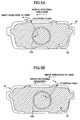
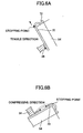
- a point of action on the shim 70 of the rotation force of the disk rotor 14 applied via the hook portion 72 is provided at a downstream side (outlet side of the disk rotor 14) in a rotating direction of the disk rotor 14 with respect to a point of action on the shim 70 of the pressuring force applied by the pressuring portion 54b of the piston 34.
- the locations of the hook portions 72 within the concave portions 55 of the back metal 54 are biased to the side of the pressuring portion 54b of the piston 34, that is to say, to the center of the back metal 54.
- distances "a" between the hook portions 72 and the inner side walls (center side walls) of the concave portions 55 are set smaller than distances "b" between the hook portions 72 and the outer side walls of the concave portions 55.
- the pressuring force from the piston 34 will act on the shim 70 in a heterogeneous pattern (the same goes for the case of rotating in the clockwise direction).
- the piston 34 presses the shim 70 in the lifted state, and the postures of the brake pads become unstable, which enhances brake shudder.
- gaps ⁇ between the side edges of the back metal 54 and the side edges of the shim 70 are set such that the side portions of the shim 70 cannot extend off the back metal 54 by considering the movable range of the shim 70 with respect to the back metal 54, as shown in Fig. 3.
- the gap ⁇ is set sufficiently bigger than the movable amount "a" of the hook portion 72 in the concave portion 55 (the distance "a” between the hook portions 72 and the center side wall of the concave portion 55).
- the present invention is not limited to this structure.
- the present invention covers any structures as long as the stopping force is applied to the hook portion 72 of the shim 70 at the outside of the pressuring portion 54b of the piston 34 and in an outward direction with respect to the pressuring portion 54b.
- the structure in which the outer side walls of the concave portions 55 are omitted is also possible.
- the stoppers between the shim 70 and the back metal 54 are implemented by the hook portions 72 of the shim 70 and the concave portions 55 of the back metal 54
- the present invention is not limited to this structure.
- a structure in which projected portions formed on the shim 70 are inserted or fitted in through holes or concave portions formed in the back metal 54, and a structure in which projected portions formed on the back metal 54 are inserted or fitted in through holes or concave portions formed in the shim 70 are also possible.
- the separate shim (referred to as "an inner shim") may be attached to the back metal 54 such that it cannot move substantially, and thus the inner shim may have a function of easing the slide (movement) of the outer shim 70.
- the same structure as the aforementioned back metal 54 may be provide to the inner shim.
- stopper portions for stopping the movement of the shim 70 may be set between the inner shim and the outer shim 70, wherein the stopper portions may apply the stopping force to the outer shim 70 at the outside of the pressuring portion 54b of the piston 34 and in an outward direction (in the rotating direction of the disk rotor 14) with respect to the pressuring portion 54b.
- the stopper portions between the back metal 54 and the shim 70 are set at the upper side of the shim 70, that is to say, at the outer side in the radius direction, however, it is also possible to set the stopper portions at the lower side of the shim 70.
- this arrangement in a case where the width of the pressuring portion 54b by the pawl portion 32 is smaller in the lower side of the shim 70 than that in the upper side of the shim 70, it becomes easier to set the stopper portions on the shim 70 at the outside of the pressuring portion 54b of the pawl portion 32 of the cylinder 30.
Landscapes
- Engineering & Computer Science (AREA)
- General Engineering & Computer Science (AREA)
- Mechanical Engineering (AREA)
- Braking Arrangements (AREA)
Applications Claiming Priority (2)
| Application Number | Priority Date | Filing Date | Title |
|---|---|---|---|
| JP2004062341 | 2004-03-05 | ||
| JP2004062341A JP4277711B2 (ja) | 2004-03-05 | 2004-03-05 | ディスクブレーキ |
Publications (2)
| Publication Number | Publication Date |
|---|---|
| EP1571364A1 EP1571364A1 (en) | 2005-09-07 |
| EP1571364B1 true EP1571364B1 (en) | 2007-12-05 |
Family
ID=34747696
Family Applications (1)
| Application Number | Title | Priority Date | Filing Date |
|---|---|---|---|
| EP05250599A Ceased EP1571364B1 (en) | 2004-03-05 | 2005-02-03 | Disk brake for a vehicle |
Country Status (5)
| Country | Link |
|---|---|
| US (1) | US7237659B2 (enExample) |
| EP (1) | EP1571364B1 (enExample) |
| JP (1) | JP4277711B2 (enExample) |
| CN (1) | CN100342149C (enExample) |
| DE (1) | DE602005003600T2 (enExample) |
Families Citing this family (15)
| Publication number | Priority date | Publication date | Assignee | Title |
|---|---|---|---|---|
| FR2907180B1 (fr) * | 2006-10-17 | 2010-03-19 | Bosch Gmbh Robert | Frein a disque de vehicule automobile comportant des moyens de rappel elastique d'une plaque de decouplage dans une position centrale de repos. |
| JP2008144889A (ja) * | 2006-12-12 | 2008-06-26 | Advics:Kk | ディスクブレーキ |
| JP4803019B2 (ja) | 2006-12-20 | 2011-10-26 | トヨタ自動車株式会社 | ディスクブレーキ装置 |
| US7726450B2 (en) * | 2007-02-12 | 2010-06-01 | Anstro Manufacturing, Inc. | Shim and a subassembly including a shim and backing plate |
| CA2645460C (en) * | 2008-11-28 | 2015-12-29 | Ray Arbesman | Piston-side brake shim |
| JP5178596B2 (ja) * | 2009-03-23 | 2013-04-10 | 曙ブレーキ工業株式会社 | ディスクブレーキ |
| JP5454352B2 (ja) | 2010-05-20 | 2014-03-26 | 株式会社アドヴィックス | ディスクブレーキ装置 |
| JP5806872B2 (ja) * | 2011-07-28 | 2015-11-10 | 日立オートモティブシステムズ株式会社 | ディスクブレーキ |
| JP5855397B2 (ja) * | 2011-09-13 | 2016-02-09 | 曙ブレーキ工業株式会社 | ディスクブレーキ用パッド組立体 |
| US8888080B1 (en) * | 2011-11-03 | 2014-11-18 | Thomas C. Deane | Animal carrier gate anti-rattle device |
| DE102013013686A1 (de) | 2013-08-16 | 2015-02-19 | Knorr-Bremse Systeme für Nutzfahrzeuge GmbH | Belaghaltefeder eines Bremsbelags und Bremsbelaghalterung für eine Scheibenbremse eines Kraftfahrzeugs |
| US10125832B2 (en) | 2015-11-12 | 2018-11-13 | Knorr-Bremse Systeme Fuer Nutzfahrzeuge Gmbh | Disc brake and brake pad set |
| PT3423731T (pt) * | 2016-03-03 | 2022-01-10 | Bendix Commercial Vehicle Systems Llc | Travão de disco e conjunto de pastilha de travão |
| GB201607866D0 (en) | 2016-05-05 | 2016-06-22 | Trw Ltd | Hydraulic disc brake assembly and pad assembly for same |
| JP6762900B2 (ja) * | 2017-03-28 | 2020-09-30 | 曙ブレーキ工業株式会社 | ディスクブレーキ用積層シム |
Family Cites Families (13)
| Publication number | Priority date | Publication date | Assignee | Title |
|---|---|---|---|---|
| JP2561569Y2 (ja) | 1991-06-17 | 1998-01-28 | 日清紡績株式会社 | ディスクブレーキ用シム組立体 |
| USD354265S (en) * | 1991-11-25 | 1995-01-10 | International Brake Industries, Inc. | Disc brake shim |
| USD336882S (en) * | 1991-11-25 | 1993-06-29 | International Brake Industries, Inc. | Disc brake shim |
| USD338648S (en) * | 1991-11-27 | 1993-08-24 | International Brake Industries, Inc. | Disc brake shim |
| USD346998S (en) * | 1993-05-12 | 1994-05-17 | International Brake Industries, Inc. | Disc brake shim |
| JP3832778B2 (ja) | 1996-10-07 | 2006-10-11 | 曙ブレーキ工業株式会社 | キャリパ型ディスクブレーキ |
| JPH10184744A (ja) * | 1996-12-27 | 1998-07-14 | Sumitomo Electric Ind Ltd | ディスクブレーキ |
| JP3863250B2 (ja) | 1997-05-16 | 2006-12-27 | 株式会社日立製作所 | ディスクブレーキ |
| JPH11223230A (ja) | 1998-02-04 | 1999-08-17 | Yuusan Gasket Kk | ディスクブレーキの鳴き防止用シムおよびディスクブレーキ |
| JP3940432B2 (ja) * | 1998-07-21 | 2007-07-04 | ユーサンガスケット株式会社 | ディスクブレーキの鳴き防止用シムおよびディスクブレーキ |
| JP2003329067A (ja) | 2002-05-16 | 2003-11-19 | Advics:Kk | ディスクブレーキ |
| JP2004257431A (ja) * | 2003-02-24 | 2004-09-16 | Advics:Kk | ディスクブレーキ |
| JP4715124B2 (ja) * | 2004-08-06 | 2011-07-06 | 株式会社アドヴィックス | ディスクブレーキ用の積層シムと該積層シムを備えるパッドユニット |
-
2004
- 2004-03-05 JP JP2004062341A patent/JP4277711B2/ja not_active Expired - Fee Related
-
2005
- 2005-01-31 US US11/046,229 patent/US7237659B2/en not_active Expired - Lifetime
- 2005-02-03 DE DE602005003600T patent/DE602005003600T2/de not_active Expired - Lifetime
- 2005-02-03 EP EP05250599A patent/EP1571364B1/en not_active Ceased
- 2005-03-02 CN CNB2005100514203A patent/CN100342149C/zh not_active Expired - Fee Related
Also Published As
| Publication number | Publication date |
|---|---|
| JP4277711B2 (ja) | 2009-06-10 |
| US7237659B2 (en) | 2007-07-03 |
| CN100342149C (zh) | 2007-10-10 |
| US20050194223A1 (en) | 2005-09-08 |
| DE602005003600T2 (de) | 2008-11-13 |
| CN1664398A (zh) | 2005-09-07 |
| JP2005249114A (ja) | 2005-09-15 |
| DE602005003600D1 (de) | 2008-01-17 |
| EP1571364A1 (en) | 2005-09-07 |
Similar Documents
| Publication | Publication Date | Title |
|---|---|---|
| EP1571364B1 (en) | Disk brake for a vehicle | |
| US20080099174A1 (en) | Brake caliper | |
| JP5076177B2 (ja) | ディスクブレーキ用摩擦パッド組立て体 | |
| US4289216A (en) | Disc brake | |
| JP5894821B2 (ja) | ディスクブレーキ | |
| US4591028A (en) | Disc brake having oppositely swingable cylinder and caliper | |
| US4915198A (en) | Friction pad support mechanism for disc brake | |
| JP2590244Y2 (ja) | ディスクブレーキにおける摩擦パッドの支持装置 | |
| EP4107405B1 (en) | Brake pad retainer system, brake pad and vehicle | |
| JPH07305734A (ja) | ディスクブレーキ | |
| US11885383B2 (en) | Disc brake pad | |
| US20220042563A1 (en) | Disc brake device | |
| WO2008079087A1 (en) | Method and device for disc brakes and vehicle | |
| JP2006336784A (ja) | 車両用ディスクブレーキ | |
| JP5468336B2 (ja) | ディスクブレーキ | |
| US20240425019A1 (en) | Retraction spring and caliper brake including the same | |
| JP3655352B2 (ja) | ディスクブレーキ | |
| JP2024147007A (ja) | ディスクブレーキ用キャリパボディ及びフローティング型ディスクブレーキ装置 | |
| EP3580470B1 (en) | Wear optimized pad design | |
| KR100826816B1 (ko) | 디스크 브레이크용 캘리퍼 어셈블리 | |
| JP4258913B2 (ja) | ディスクブレーキ | |
| CN117460901A (zh) | 盘式制动器及垫弹簧 | |
| JPH0313631Y2 (enExample) | ||
| JPH0348422Y2 (enExample) | ||
| JP2001173688A (ja) | ドラムブレーキ装置 |
Legal Events
| Date | Code | Title | Description |
|---|---|---|---|
| PUAI | Public reference made under article 153(3) epc to a published international application that has entered the european phase |
Free format text: ORIGINAL CODE: 0009012 |
|
| 17P | Request for examination filed |
Effective date: 20050217 |
|
| AK | Designated contracting states |
Kind code of ref document: A1 Designated state(s): AT BE BG CH CY CZ DE DK EE ES FI FR GB GR HU IE IS IT LI LT LU MC NL PL PT RO SE SI SK TR |
|
| AX | Request for extension of the european patent |
Extension state: AL BA HR LV MK YU |
|
| AKX | Designation fees paid |
Designated state(s): DE FR GB |
|
| 17Q | First examination report despatched |
Effective date: 20051222 |
|
| GRAP | Despatch of communication of intention to grant a patent |
Free format text: ORIGINAL CODE: EPIDOSNIGR1 |
|
| GRAS | Grant fee paid |
Free format text: ORIGINAL CODE: EPIDOSNIGR3 |
|
| GRAA | (expected) grant |
Free format text: ORIGINAL CODE: 0009210 |
|
| AK | Designated contracting states |
Kind code of ref document: B1 Designated state(s): DE FR GB |
|
| REG | Reference to a national code |
Ref country code: GB Ref legal event code: FG4D |
|
| REF | Corresponds to: |
Ref document number: 602005003600 Country of ref document: DE Date of ref document: 20080117 Kind code of ref document: P |
|
| ET | Fr: translation filed | ||
| PLBE | No opposition filed within time limit |
Free format text: ORIGINAL CODE: 0009261 |
|
| STAA | Information on the status of an ep patent application or granted ep patent |
Free format text: STATUS: NO OPPOSITION FILED WITHIN TIME LIMIT |
|
| 26N | No opposition filed |
Effective date: 20080908 |
|
| REG | Reference to a national code |
Ref country code: GB Ref legal event code: 746 Effective date: 20121112 |
|
| REG | Reference to a national code |
Ref country code: DE Ref legal event code: R084 Ref document number: 602005003600 Country of ref document: DE Effective date: 20121115 |
|
| REG | Reference to a national code |
Ref country code: FR Ref legal event code: PLFP Year of fee payment: 12 |
|
| REG | Reference to a national code |
Ref country code: FR Ref legal event code: PLFP Year of fee payment: 13 |
|
| REG | Reference to a national code |
Ref country code: FR Ref legal event code: PLFP Year of fee payment: 14 |
|
| PGFP | Annual fee paid to national office [announced via postgrant information from national office to epo] |
Ref country code: DE Payment date: 20190122 Year of fee payment: 15 Ref country code: FR Payment date: 20190111 Year of fee payment: 15 Ref country code: GB Payment date: 20190130 Year of fee payment: 15 |
|
| REG | Reference to a national code |
Ref country code: DE Ref legal event code: R119 Ref document number: 602005003600 Country of ref document: DE |
|
| GBPC | Gb: european patent ceased through non-payment of renewal fee |
Effective date: 20200203 |
|
| PG25 | Lapsed in a contracting state [announced via postgrant information from national office to epo] |
Ref country code: FR Free format text: LAPSE BECAUSE OF NON-PAYMENT OF DUE FEES Effective date: 20200229 Ref country code: DE Free format text: LAPSE BECAUSE OF NON-PAYMENT OF DUE FEES Effective date: 20200901 Ref country code: GB Free format text: LAPSE BECAUSE OF NON-PAYMENT OF DUE FEES Effective date: 20200203 |