EP1570825A1 - Verfahren zur herstellung eines festen sammel-form-elements - Google Patents
Verfahren zur herstellung eines festen sammel-form-elements Download PDFInfo
- Publication number
- EP1570825A1 EP1570825A1 EP03812278A EP03812278A EP1570825A1 EP 1570825 A1 EP1570825 A1 EP 1570825A1 EP 03812278 A EP03812278 A EP 03812278A EP 03812278 A EP03812278 A EP 03812278A EP 1570825 A1 EP1570825 A1 EP 1570825A1
- Authority
- EP
- European Patent Office
- Prior art keywords
- middle portion
- forming member
- making
- sheet
- guide
- Prior art date
- Legal status (The legal status is an assumption and is not a legal conclusion. Google has not performed a legal analysis and makes no representation as to the accuracy of the status listed.)
- Granted
Links
Images


Classifications
-
- A—HUMAN NECESSITIES
- A61—MEDICAL OR VETERINARY SCIENCE; HYGIENE
- A61F—FILTERS IMPLANTABLE INTO BLOOD VESSELS; PROSTHESES; DEVICES PROVIDING PATENCY TO, OR PREVENTING COLLAPSING OF, TUBULAR STRUCTURES OF THE BODY, e.g. STENTS; ORTHOPAEDIC, NURSING OR CONTRACEPTIVE DEVICES; FOMENTATION; TREATMENT OR PROTECTION OF EYES OR EARS; BANDAGES, DRESSINGS OR ABSORBENT PADS; FIRST-AID KITS
- A61F13/00—Bandages or dressings; Absorbent pads
- A61F13/15—Absorbent pads, e.g. sanitary towels, swabs or tampons for external or internal application to the body; Supporting or fastening means therefor; Tampon applicators
- A61F13/15577—Apparatus or processes for manufacturing
- A61F13/15585—Apparatus or processes for manufacturing of babies' napkins, e.g. diapers
- A61F13/15593—Apparatus or processes for manufacturing of babies' napkins, e.g. diapers having elastic ribbons fixed thereto; Devices for applying the ribbons
-
- A—HUMAN NECESSITIES
- A61—MEDICAL OR VETERINARY SCIENCE; HYGIENE
- A61F—FILTERS IMPLANTABLE INTO BLOOD VESSELS; PROSTHESES; DEVICES PROVIDING PATENCY TO, OR PREVENTING COLLAPSING OF, TUBULAR STRUCTURES OF THE BODY, e.g. STENTS; ORTHOPAEDIC, NURSING OR CONTRACEPTIVE DEVICES; FOMENTATION; TREATMENT OR PROTECTION OF EYES OR EARS; BANDAGES, DRESSINGS OR ABSORBENT PADS; FIRST-AID KITS
- A61F13/00—Bandages or dressings; Absorbent pads
- A61F13/15—Absorbent pads, e.g. sanitary towels, swabs or tampons for external or internal application to the body; Supporting or fastening means therefor; Tampon applicators
- A61F13/15577—Apparatus or processes for manufacturing
- A61F13/15707—Mechanical treatment, e.g. notching, twisting, compressing, shaping
- A61F13/15747—Folding; Pleating; Coiling; Stacking; Packaging
-
- Y—GENERAL TAGGING OF NEW TECHNOLOGICAL DEVELOPMENTS; GENERAL TAGGING OF CROSS-SECTIONAL TECHNOLOGIES SPANNING OVER SEVERAL SECTIONS OF THE IPC; TECHNICAL SUBJECTS COVERED BY FORMER USPC CROSS-REFERENCE ART COLLECTIONS [XRACs] AND DIGESTS
- Y10—TECHNICAL SUBJECTS COVERED BY FORMER USPC
- Y10T—TECHNICAL SUBJECTS COVERED BY FORMER US CLASSIFICATION
- Y10T156/00—Adhesive bonding and miscellaneous chemical manufacture
- Y10T156/10—Methods of surface bonding and/or assembly therefor
- Y10T156/1002—Methods of surface bonding and/or assembly therefor with permanent bending or reshaping or surface deformation of self sustaining lamina
- Y10T156/1007—Running or continuous length work
- Y10T156/1015—Folding
-
- Y—GENERAL TAGGING OF NEW TECHNOLOGICAL DEVELOPMENTS; GENERAL TAGGING OF CROSS-SECTIONAL TECHNOLOGIES SPANNING OVER SEVERAL SECTIONS OF THE IPC; TECHNICAL SUBJECTS COVERED BY FORMER USPC CROSS-REFERENCE ART COLLECTIONS [XRACs] AND DIGESTS
- Y10—TECHNICAL SUBJECTS COVERED BY FORMER USPC
- Y10T—TECHNICAL SUBJECTS COVERED BY FORMER US CLASSIFICATION
- Y10T156/00—Adhesive bonding and miscellaneous chemical manufacture
- Y10T156/10—Methods of surface bonding and/or assembly therefor
- Y10T156/1002—Methods of surface bonding and/or assembly therefor with permanent bending or reshaping or surface deformation of self sustaining lamina
- Y10T156/1051—Methods of surface bonding and/or assembly therefor with permanent bending or reshaping or surface deformation of self sustaining lamina by folding
Definitions
- the present invention relates to a method and apparatus for making a standing gather-forming member used in absorbent articles such as sanitary napkins and incontinence pads.
- JP-A-1-68503 discloses a disposable diaper having a pair of standing gathers outside of the lateral edges of the absorbent member.
- the standing gathers have a T-shaped cross-section composed of a basal wall and overhangs on both lateral sides of the basal wall.
- the disposable diaper is adapted to have the upper side of the T-shaped standing gathers applied to the wearer's thighs thereby to prevent leaks.
- An object of the present invention is to provide a method and apparatus for making a standing gather-forming member, by which a standing gather-forming member providing a snug fit and a reliable protection against leakage is produced continuously and stably.
- the present invention accomplishes the above object by providing a method of making a standing gather-forming member having a basal wall and first and second overhangs sticking from the basal wall to both lateral sides.
- the method includes a first step of forming the first overhang and a second step of forming the second overhang and the basal wall that follows the first step.
- an elastic member is disposed in its stretched state on the inner surface of a middle portion of a continuously running strip-shaped sheet in the longitudinal direction of the middle portion, and one of side portions extending on both longitudinal sides of the middle portion is Z-folded so as to cover a part of the width of the middle portion.
- the other side portion is folded inward along the longitudinal direction so as to cover the part of the middle portion that remains uncovered with the first-mentioned side portion and also overlay the Z-folded portion of the first-mentioned side portion.
- the present invention also accomplishes the above object by providing apparatus for making a standing gather-forming member having a basal wall and first and second overhangs laterally extending from the basal wall.
- the apparatus has a conveying system for conveying along a conveying route a strip-shaped sheet having an elastic member disposed on the middle portion thereof in its stretched state, a first folding unit having a first guide provided on one side of the conveying route so as to narrow the width of the conveying route from that side, and a second folding unit having a second guide provided on the other side of the conveying route so as to narrow the width of the conveying route from the other side.
- the first guide has an inwardly projecting projection configured to hang over a part of the middle portion on the conveying route.
- the second guide has an inwardly projecting projection configured to hang over a part of the middle portion.
- the projection of the first guide is configured to Z-fold one of side portions extending on both longitudinal sides of the middle portion such that the side portion covers a part of the middle portion to form the first overhang.
- the projection of the second guide is configured to fold the other side portion inward along the longitudinal direction such that the other side portion covers the part of the middle portion that remains uncovered with the first-mentioned side portion and also overlay the Z-folded portion of the first-mentioned side portion to form the second overhang and the basal wall.
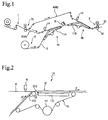
- Fig. 1 illustrates an embodiment of the present invention in which apparatus for making a standing gather-forming member (hereinafter simply referred to as “the apparatus") is applied to the production of a standing gather-forming member for use in sanitary napkins.
- the apparatus of the present embodiment has a first folding unit 1A, a second folding unit 1B, a sheet feeder 6, an elastic member feeder 7, an adhesive applicator 8 for bonding both side portions of a sheet, and a pressing unit 9.
- the apparatus of the present embodiment is for making a member providing standing gathers 3 which is used in a sanitary napkin 2 as shown in Fig. 7.
- a standing gather-forming member made by this apparatus has a basal wall 30, a first overhang 31, and a second overhang 32 extending from the basal wall 30 to the opposing lateral directions to make a substantially T-shaped cross-section.
- a plurality of elastic members 4 of thread form are arranged in each of the first and the second overhangs 31 and 32.
- the standing gathers 3 have a height H of 5 to 50 mm and a width W, represented by the distance between the edge of the first overhang 31 and the edge of the second overhang 32, of 6 to 40 mm.
- the sheet feeder 6 is configured to continuously unwind a continuous strip-shaped sheet 5 from a stock roll and feed the sheet 5 to a conveyor 11A of the first folding unit 1A.
- the sheet 5 is folded in a prescribed manner in the first folding unit 1A while being carried by the conveyor 11A and then forwarded to a conveyor 11B of the second folding unit 1A, where it is folded in a prescribed manner while being conveyed by the conveyor 11B.
- the conveyor 11A of the first folding unit 1A and the conveyor 11B of the second folding unit 1B are configured to convey the sheet 5 in that order.
- a combination of the conveyors 11A and 11B constitutes a conveying system in the apparatus of the invention.
- the first folding unit 1A has a conveyor 11A and a first guide 12.
- the conveyor 11A conveys the strip-shaped sheet 5 along the conveying route R, the sheet 5 having four elastic members 4A disposed on the inner surface of its middle portion 50 in their stretched state.
- the first guide 12 is provided on one side of the conveying route R so as to narrow the width of the conveying route R from that side.
- the first guide 12 has an inwardly projecting projection 120 that hangs over a part of the middle portion 50 moving on the conveying route R.
- the second folding unit 1B has a conveyor 11B and a second guide 13.
- the conveyor 11B conveys the strip-shaped sheet 5 along the conveying route R, the sheet 5 having six elastic members 4 disposed on the inner surface of its middle portion 50 in their stretched state.
- the second guide 13 is provided on the other side of the conveying route R so as to narrow the width of the conveying route R from that side.
- the second guide 13 has an inwardly projecting projection 130 that hangs over a part of the middle portion 50 on the conveying route R.
- the six elastic members 4 are the sum of the four elastic members 4A having been arranged on the middle portion while on the conveyer 11A and two additional elastic members 4B arranged on the middle portion while on the conveyor 11B.
- the conveyor 11A of the first folding unit 1A and the conveyor 11B of the second folding unit 1B each have an air-permeable endless belt 110 for conveying the sheet 5, a group of rolls including a driving roll 111 driving the belt 110 along the conveying route R, and a vacuum box as a suction mechanism for fixing the middle portion 50 on the belt 110 by suction.
- the conveyor belts 112 in the conveyors 11A and 11B are each provided so that the middle portion 50 of the sheet 5 may make a prescribed angle ⁇ between before and after entering the area where the overhang is formed by the first and the second guides 12 and 13.
- the angle ⁇ is preferably 100° to 150°, more preferably 135° to 145°, from the suction surface of the conveyor, taking the conveying surface as a base. At angles of 100° or greater, the sheet 5 is prevented from failing to be shaped due to sagging. At angles of 150° or smaller, the sheet 5 is prevented from failing to be shaped due to excessive tension.
- the projection 120 of the first guide 12 has a trapezoidal shape with its upstream end tapered in its plan view.
- the projection 120 is designed to Z-fold a side portion 51 located by one side of the middle portion 50 to partly cover the middle portion 50, i.e., to form the first overhang 31.
- the upstream end 121 of the first guide 12 rises obliquely.
- the angle of rise, designated ⁇ 12 is preferably 5° to 15°, more preferably 10° to 12°, from the conveying surface. At angles of 5° or greater, the sheet 5 is prevented from failing to be folded. At angles of 15° or smaller, the sheet 5 is prevented from suffering from shaping defects such as wrinkles.
- the folding angle ⁇ 120 of the upstream taper of the projection 120 of the first guide 12 is preferably 8° to 15°, more preferably 10° to 12°, measured from the outer face of the first guide 12 perpendicular to the conveying route R (hereinafter referred to as "edge face"). At angles of 8° or greater, shaping defects due to the failure of the sheet 5 to be folded is avoided. At angles of 15° or smaller, the sheet is prevented from wrinkling due to the steep rise.
- the projecting width W 12 of the projection 120 is preferably 8 to 15 mm, more preferably 10 to 12 mm, measured from the edge face of the first guide 12. With widths of 8 mm or greater, the fold width by the first guide is surely reflected in the resulting Z-fold. With widths of 15 mm or smaller, it is easy to control the dimension of the sheet as desired, and shaping defects such as wrinkles are prevented.
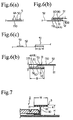
- the distance D12 (see Fig. 6(b)) between the lower side of the projection 120 and the upper side of the belt 110 is preferably 1.0 to 2.5 mm, more preferably 1.5 to 2.0 mm, at folding end point E12 (see Fig. 4(a)) of the first guide 12. With distances of 1.0 mm or greater, shaping defects such as wrinkles due to increased resistance of the sheet 5 are avoided. With distances of 2.5 mm or smaller, shaping defects such as wrinkles are prevented.
- the second guide 13 of the second folding unit 1B is provided on the side of the conveying route R opposite to the side where the first guide 12 is provided so as to narrow the width of the conveying route R from that side.
- the second guide 13 has an inwardly projecting projection 130 that hangs over a part of the middle portion 50 on the conveying route R.
- the projection 130 has a V shape across the conveying route R in the plan view.
- the projection 130 of the second guide 13 is designed to inwardly fold the side portion 52, which is another one of the side portions located by both sides of the middle portion 50, along the longitudinal direction so as to cover the part of the middle portion 50 that remains uncovered with the side portion 51 and also to overlay the upper side of the Z-folded portion of the side portion 51, thereby to form the second overhang 32 and the basal wall 30.
- the upstream end 131 of the second guide 13 rises obliquely.
- the angle of rise, designated ⁇ 13 is preferably 5° to 15°, more preferably 8° to 10°, in view of the fabricability of the material.
- the folding angle ⁇ 130 of the upstream taper of the projection 130 of the second guide 13 is preferably 5° to 15°, more preferably 8° to 10°, in view of the fabricability into the standing gathers.
- the distance D13 (see Fig. 6(d)) between the lower side of the projection 130 of the second guide 13 and the facing upper side of the belt 110 (conveyor) is larger than the distance D12 (see Fig. 6(b)) between the lower side of the projection 120 of the first guide 12 and the facing upper side of the belt 110 (conveyor).
- Symbol C 13 in Fig. 5(a) indicates a position in the width direction of the conveying route R, the position corresponding to the folding end point E1 of the first guide 12 (approximately the widthwise mid point).
- the distance D13 at that point C13 is preferably 1.0 to 2.5 mm, more preferably 1.5 to 2.0 mm, in order to prevent positional deviation in folding and to stabilize the folding operation. It is preferred that the distances D13 and D12 be equal.
- the first and the second folding units 1A and 1B each have an applicator 14 for applying an adhesive at intervals to the elastic members 4 immediately before being set on the respective conveyors 11 A and 11B.
- Each applicator 14 is equipped with a comb nozzle having orifices for ejecting an adhesive at prescribed spacings corresponding to those of the elastic members 4.
- the applicator 14 of the first folding unit 1A is configured to eject an adhesive from orifices 14a corresponding to the four elastic members 4A and apply the adhesive to the elastic members 4A.
- the applicator 14 of the second folding unit 1B is configured to eject an adhesive from orifices 14a corresponding to the two elastic members 4B and apply the adhesive to the elastic members 4B as illustrated in Fig. 5(b).
- the elastic member feeder 7 is configured to continuously feed six elastic members 4 from the stock roll, divide the six elastic members 4 into four elastic members 4A and two elastic members 4B by means of a distributor 70, and arrange the former group of the elastic members 4A on the middle portion 50 moving on the first folding unit 1A and the latter group of the elastic members 4B on the middle portion 50 moving on the second folding unit 1B.
- the adhesive applicator 8 for bonding both side portions of the sheet is positioned between the first folding unit 1A and the second folding unit 1B as shown in Fig. 1.
- the adhesive applicator 8 is configured to apply an adhesive to the side portion 52 at intervals so that the side portions 51 and 52 may be partly joined together when superposed on each other in the second folding unit 1B.
- the pressing unit 9 has a pair of nip rolls 91 and 92.
- the pressing unit 9 is configured to press the standing gather-forming material, after the formation of the first and the second overhangs and the basal wall, between the nip to enhance the adhesion between the elastic members 4 and the sheet 5 and between the two side portions of the sheet 5.
- a strip-shaped sheet 5 is fed onto the conveyor 11A of the first folding unit 1A by means of the sheet feeder 6.
- the sheet 5 is conveyed along the conveying route R while being sucked to the belt 110 by the vacuum box 112 of the conveyor 11A.
- Four elastic members 4 are arranged with almost equal spacing in their stretched state on the inner side of the middle portion 50 of the moving sheet 5 (see Fig. 6(b)).
- an adhesive is applied thereto by the applicator 14 so that the elastic members 4 are fixed to the sheet 5 via the adhesive.
- the conveying route is narrowed from one side by the guide 12, and the side portion 51 (one of the side portions 51 and 52 extending along both sides of the middle portion 50) is Z-folded by the projection 120 of the guide 12 so as to cover the whole width of the part of the middle portion 50 where the elastic members 4A are disposed.
- the first overhang 31 of the standing gathers 3 is formed (see Fig. 6(b)).
- An adhesive 53 is intermittently applied with the adhesive applicator 8 to a prescribed part of the side portion 52, the other side portion of the two side portions 51 and 52 of the sheet 5 which are to be superposed on each other in the second folding unit 1B hereinafter described (see Fig. 6(c)).
- Any of various adhesives used in sanitary napkins can be used as adhesive 53 to form the basal wall 30 with no particular restriction.
- the adhesive 53 may be applied to the area of the side portion 51 on which the side portion 52 is to be superposed, or the adhesive 53 may be applied to both the side portions 51 and 52.
- the folded sheet 5 from the first folding unit 1A is sent to the conveyor 11B of the first folding unit 1B and conveyed as sucked to the belt 110 by the vacuum box (not shown) of the conveyor 11B.
- Two elastic members 4 are disposed in their stretched state on the inner side of the middle portion 50 of the moving sheet 5 along the longitudinal direction of the middle portion 50 (see Fig. 5(b)). Before these elastic members 4B are disposed, an adhesive is applied thereto by the applicator 14 so that the elastic members 4B are fixed to the sheet 5 via the adhesive.
- the side portion 52 which is another one of the side portions 51 and 52, is folded inward along the longitudinal direction by the projection 130 of the guide 13 so as to cover the part of the middle portion 50 that remains uncovered with the side portion 51 and also overlay the upper side of the Z-folded portion of the side portion 51, thereby to form the second overhang 32 and the basal wall 30 (see Fig. 6(d)).
- the standing gather-forming member thus obtained has the first overhang 31 and the second overhang 32 sticking out almost horizontally to both lateral sides of the basal wall 30 so that the upper sides of the first and the second overhangs are in the same plane (the outer surface of the middle portion).
- the standing gather-forming member is compressed by the pressing unit 9 to secure the adhesion between the elastic members 4 and the sheet 5 and between the two side portions of the sheet 5.
- the end of the basal wall 30 is precut and transferred to a sanitary napkin production line.
- the apparatus of the present embodiment and the method of making a standing gather-forming member using the apparatus make it possible to continuously and stably produce a standing gather-forming member that will provide a good fit and secure safety against leakage.
- the belts 110 (conveyors) of the first and the second folding units 1A and 1B convey the sheet 5 at the same speed.
- the conveying speed is preferably 50 to 200 m/min, more preferably 100 to 150 m/min, taking into consideration the fabricability into standing gathers and the stability of various dimensions.
- the middle portion 50 of the sheet 5 make a prescribed angle ⁇ when it enters the area where the overhang is to be formed by the first or the second guides 12 or 13, the angle 6 being defined to be the angle between the conveying route R' before entering the area and the conveying route R after entering the area.
- the angle ⁇ is preferably 100° to 150°, more preferably 135° to 145°, from the standpoint of stable processing.
- the vacuum box 112 preferably creates a negative pressure or suction force of 980 to 9800 Pa, more preferably 4900 to 7840 Pa, for securely holding the sheet material and the elastic members.
- the sheet 5 making the standing gathers 3 is preferably of material with a pleasant feel because the gathers 3 are to come into direct contact with the skin. It is also preferred for the material to be hydrophobic to prevent liquid of low surface tension from passing therethrough. As a sheet meeting these requirements, it is recommended to use air-through nonwoven, spun-bonded nonwoven or spunbonded/meltblown composite nonwoven each made of hydrophobic fiber or having been rendered hydrophobic.
- the nonwoven fabric In making the standing gathers 3 of nonwoven fabric, it is preferred for the nonwoven fabric to have a bulk softness of 0.03 to 0.3 N, more preferably 0.05 to 0.2 N, measured in the length direction of the gathers and of 0.05 to 0.5 N, more preferably 0.07 to 0.3 N, measured in the width direction (height direction) of the gathers. It is preferred that the bulk softness in the width direction be equal to or higher than that in the length direction. Where the bulk softness values in the length and the width directions and the bulk softness relationship between the length and the width directions meet the above recited preferred conditions, it is easier for the elastic members 4 disposed in the overhangs 31 and 32 to contract in their length direction.
- planar seal effect by the overhangs 31 and 32 of the standing gathers 3 and the upright state of the standing gathers 3 are stably maintained irrespective of wearer's movement.
- the bulk softness in the width direction can be made higher than that in the length direction preferably by, for example, embossing the nonwoven fabric in a wavy pattern across the width.
- the bulk softness is measured as follows.
- a Tensilon tester (RTM-25, supplied by Toyo Baldwin Co., Ltd.) is used for the measurement.
- a 10 mm by 120 mm piece is cut out of a nonwoven fabric, and the two short sides of the cut piece are joined and stapled at the upper and the lower parts to make a 10 mm high cylindrical specimen.
- the specimen is compressed in the height direction at a rate of 10 mm/min, and the maximum load is measured as a bulk softness.
- a bulk softness in the length direction is a value obtained when the compression direction coincides with the length direction of the nonwoven fabric.
- a bulk softness in the width direction is a value measured with the compression direction coinciding with the width direction of the nonwoven fabric.
- any of various elastic materials conventionally used in sanitary napkins, disposable diapers, etc. can be used as elastic members 4 with no particular limitations.
- foamed polyolefins, foamed polyurethane, and natural rubber are of choice.
- the form of the elastic members 4 includes a thread, a strip, and a film. Arrangement, extensibility, and/or the number of the elastic members 4 are subject to alteration in accordance with the form of the elastic members and the use of the sanitary napkin.
- the elastic members 4 are fixed to the inner side of the sheet 5 in their stretched state. Means for fixing the elastic members 4 include anything that is commonly used in sanitary napkins. Hot melt adhesives and heat sealing are preferred.
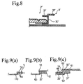
- Fig. 8 illustrates a sanitary napkin 2' in which the standing gathers 3' have overhangs 31' and 32' that are different in height.
- This modification is achieved by, for example, as follows. A level difference is made in each of the two belts 110 (as conveyors) of the first and the second folding units 1A and 1B. A sheet 5 is put on the stepped conveyor belt 110 of the first folding unit 1A and conveyed with the level difference transferred to its middle portion 50.
- a prescribed number of elastic members 4A are arranged in their stretched state on the inner surface of the moving middle portion 50 along the longitudinal direction as shown in Fig. 9(a).
- the side portion 51 (one of the side portions extending on both sides of the middle portion 50) is Z-folded by the first guide 12 such that the Z-folded side portion 51 covers the area of the middle portion 50 where the elastic members 4A are disposed thereby to form the first overhang 31'.
- the sheet 5 having formed the first overhang 31' is then forwarded to the conveying belt 110 of the second folding unit 1B while keeping the level difference as shown in Fig. 9(c).
- the rest of the elastic members i.e., elastic members 4B
- the other side portion 52 is folded inward along the longitudinal direction by the second guide 13 to cover the area of the middle portion 50 remaining uncovered by the side portion 51 and also to be superposed on the Z-folded side portion 51.
- the second overhang 32' and the basal wall 30' are formed.
- a standing gather-forming member having the above-described cross-section is also obtained by using apparatus in which only the conveyor belt 110 of the second folding unit 1B has a level difference while the conveyor belt 110 of the first folding unit 1A has a flat (stepless) surface.
- a plurality of elastic members 4 are arranged in each of the first and the second overhangs in their stretched state. Some of the elastic members 4 are arranged on the middle portion in the first step, and the rest of the elastic members are arranged on the middle portion in the second step. Otherwise, it is possible that all the elastic members are disposed on the middle portion 50 in the first step.
- folding the side portion 51 in the first folding unit 1A and folding the side portion 52 in the second folding unit 1B are preferably carried out while the middle portion 50 of the sheet 5 is attached to the conveyor belts 110 by the respective suction mechanisms 112 in the first and the second folding units 1A and 1B. Where necessary, suction by the suction mechanisms 112 may be omitted.
- the two overhangs both have the elastic members 4 disposed with equal spacing as in the foregoing embodiments
- the elastic members may be disposed in only one of the overhangs 31 and 32 by altering the arrangement of the elastic members 4 in the middle portion 50.
- the bonding of the basal wall 30 may be omitted if desired.
- the adhesive be applied to the elastic members 4 at intervals for fixing the elastic members 4 to the sheet 5 as in the foregoing embodiments, application of the adhesive to the elastic members 4 may be continuous.
- the present invention is applicable to the manufacture of not only sanitary napkins but also other absorbent articles including disposable diapers and incontinence pads.
- the present invention provides a method and apparatus for making a standing gather-forming member, by which a standing gather-forming member providing a snug fit and a reliable protection against leakage is produced continuously and stably.
Landscapes
- Health & Medical Sciences (AREA)
- Engineering & Computer Science (AREA)
- Vascular Medicine (AREA)
- Epidemiology (AREA)
- Biomedical Technology (AREA)
- Heart & Thoracic Surgery (AREA)
- Manufacturing & Machinery (AREA)
- Life Sciences & Earth Sciences (AREA)
- Animal Behavior & Ethology (AREA)
- General Health & Medical Sciences (AREA)
- Public Health (AREA)
- Veterinary Medicine (AREA)
- Mechanical Engineering (AREA)
- Absorbent Articles And Supports Therefor (AREA)
Applications Claiming Priority (3)
| Application Number | Priority Date | Filing Date | Title |
|---|---|---|---|
| JP2002348980A JP3886446B2 (ja) | 2002-11-29 | 2002-11-29 | 立体ギャザー形成用部材の製造方法 |
| JP2002348980 | 2002-11-29 | ||
| PCT/JP2003/012731 WO2004049988A1 (ja) | 2002-11-29 | 2003-10-03 | 立体ギャザー形成用部材の製造方法 |
Publications (3)
| Publication Number | Publication Date |
|---|---|
| EP1570825A1 true EP1570825A1 (de) | 2005-09-07 |
| EP1570825A4 EP1570825A4 (de) | 2009-07-29 |
| EP1570825B1 EP1570825B1 (de) | 2011-12-07 |
Family
ID=32462944
Family Applications (1)
| Application Number | Title | Priority Date | Filing Date |
|---|---|---|---|
| EP03812278A Expired - Lifetime EP1570825B1 (de) | 2002-11-29 | 2003-10-03 | Verfahren zur herstellung eines stehenden sammel-form-elements |
Country Status (6)
| Country | Link |
|---|---|
| US (1) | US7435309B2 (de) |
| EP (1) | EP1570825B1 (de) |
| JP (1) | JP3886446B2 (de) |
| CN (1) | CN100569201C (de) |
| AU (1) | AU2003277493A1 (de) |
| WO (1) | WO2004049988A1 (de) |
Families Citing this family (20)
| Publication number | Priority date | Publication date | Assignee | Title |
|---|---|---|---|---|
| US20100163564A1 (en) * | 2007-04-05 | 2010-07-01 | M&Q Packaging Corporation | Slow cooker liner with securing band |
| MX2009010687A (es) * | 2007-04-05 | 2009-12-11 | M & Q Packaging Corp | Metodo de elaboracion de un forro para aparato de coccion lenta con banda de aseguramiento. |
| JP4657317B2 (ja) * | 2008-04-28 | 2011-03-23 | 花王株式会社 | 吸収性物品の製造方法 |
| US9700465B2 (en) * | 2009-06-02 | 2017-07-11 | The Procter & Gamble Company | Disposable absorbent article with elastically contractible cuffs for better containment of liquid exudates |
| MX2010013787A (es) * | 2008-06-13 | 2010-12-21 | Procter & Gamble | Articulo absorbente desechable con dobleces elasticamente contractiles para una mejor contencion de exudados liquidos. |
| US8257535B2 (en) * | 2008-08-29 | 2012-09-04 | Uni-Charm Corporation | Manufacturing method of absorbent article |
| JP5396132B2 (ja) | 2009-04-03 | 2014-01-22 | ユニ・チャーム株式会社 | 吸収性物品製造装置、及び、吸収性物品を製造する方法 |
| JP5529644B2 (ja) * | 2010-06-22 | 2014-06-25 | 花王株式会社 | 吸収性物品及びその製造方法 |
| US9050213B2 (en) | 2012-03-30 | 2015-06-09 | The Procter & Gamble Company | Apparatuses and methods for making absorbent articles |
| US9028632B2 (en) | 2012-03-30 | 2015-05-12 | The Procter & Gamble Company | Apparatuses and methods for making absorbent articles |
| US9039855B2 (en) | 2012-03-30 | 2015-05-26 | The Procter & Gamble Company | Apparatuses and methods for making absorbent articles |
| US8440043B1 (en) | 2012-03-30 | 2013-05-14 | The Procter & Gamble Company | Absorbent article process and apparatus for intermittently deactivating elastics in elastic laminates |
| US20130255861A1 (en) | 2012-03-30 | 2013-10-03 | Uwe Schneider | Apparatuses and Methods for Making Absorbent Articles |
| JP6088298B2 (ja) * | 2013-03-08 | 2017-03-01 | ユニ・チャーム株式会社 | 使い捨て着用物品およびその製造方法 |
| US9259362B2 (en) | 2013-05-22 | 2016-02-16 | Kimberly-Clark Worldwide, Inc. | Absorbent article with containment flaps |
| US9168181B2 (en) | 2013-05-22 | 2015-10-27 | Kimberly-Clark Worldwide, Inc. | Method of forming a containment system for an absorbent article |
| US9629757B2 (en) | 2013-05-22 | 2017-04-25 | Kimberly-Clark Worldwide, Inc. | Absorbent article including containment flaps |
| WO2015047805A1 (en) * | 2013-09-27 | 2015-04-02 | The Procter & Gamble Company | Apparatus and method for isolating a broken elastic strand |
| CN203568564U (zh) * | 2013-10-25 | 2014-04-30 | 株式会社瑞光 | 折弯装置 |
| CN106913423B (zh) * | 2016-08-31 | 2019-11-12 | 黄山富田精工制造有限公司 | 输送装置 |
Family Cites Families (11)
| Publication number | Priority date | Publication date | Assignee | Title |
|---|---|---|---|---|
| US4488927A (en) * | 1983-05-16 | 1984-12-18 | The Procter & Gamble Company | Apparatus for C-folding a covering web about a longitudinally flexible article |
| JPS6468503A (en) | 1987-09-07 | 1989-03-14 | Uni Charm Corp | Disposable diaper |
| US6706029B1 (en) * | 1987-09-07 | 2004-03-16 | Uni-Charm Corporation | Disposable diaper |
| US4900384A (en) * | 1988-06-15 | 1990-02-13 | Kimberly-Clark Corporation | Method and apparatus for making elasticized containment flaps |
| US5190606A (en) * | 1991-06-14 | 1993-03-02 | Paper Converting Machine Company | Method for producing raised leg cuff for diapers including two folding boards |
| FR2711057B1 (fr) * | 1993-10-13 | 1996-02-02 | Peaudouce | Article d'hygiène absorbant jetable, pourvu d'un voile de surface s'ajustant au corps d'un utilisateur. |
| US5714027A (en) * | 1996-03-22 | 1998-02-03 | The Procter & Gamble Company | Method of folding and handling a web of material in a continuous operation |
| JP2001095839A (ja) * | 1999-09-30 | 2001-04-10 | Toyo Eizai Corp | 吸収性物品 |
| JP3737399B2 (ja) | 2001-07-24 | 2006-01-18 | 花王株式会社 | 立体ギャザー形成用部材の製造方法 |
| JP3576522B2 (ja) | 2001-11-05 | 2004-10-13 | 花王株式会社 | 伸縮性シート部材の製造方法 |
| US20040102756A1 (en) * | 2002-11-27 | 2004-05-27 | Yuzo Ichiura | Absorbent article and method for producing the same |
-
2002
- 2002-11-29 JP JP2002348980A patent/JP3886446B2/ja not_active Expired - Fee Related
-
2003
- 2003-10-03 US US10/536,895 patent/US7435309B2/en not_active Expired - Fee Related
- 2003-10-03 AU AU2003277493A patent/AU2003277493A1/en not_active Abandoned
- 2003-10-03 WO PCT/JP2003/012731 patent/WO2004049988A1/ja not_active Ceased
- 2003-10-03 EP EP03812278A patent/EP1570825B1/de not_active Expired - Lifetime
- 2003-10-03 CN CN200380104472.1A patent/CN100569201C/zh not_active Expired - Fee Related
Also Published As
| Publication number | Publication date |
|---|---|
| US7435309B2 (en) | 2008-10-14 |
| WO2004049988A1 (ja) | 2004-06-17 |
| EP1570825B1 (de) | 2011-12-07 |
| JP2004180787A (ja) | 2004-07-02 |
| EP1570825A4 (de) | 2009-07-29 |
| JP3886446B2 (ja) | 2007-02-28 |
| CN100569201C (zh) | 2009-12-16 |
| US20060151091A1 (en) | 2006-07-13 |
| CN1717210A (zh) | 2006-01-04 |
| AU2003277493A1 (en) | 2004-06-23 |
Similar Documents
| Publication | Publication Date | Title |
|---|---|---|
| EP1570825B1 (de) | Verfahren zur herstellung eines stehenden sammel-form-elements | |
| KR100368365B1 (ko) | 탄성화된 이어부분의 조립방법 | |
| US4900384A (en) | Method and apparatus for making elasticized containment flaps | |
| EP1269949B1 (de) | Herstellungsverfahren für absorbierende Artikel mit Seitenteilen | |
| EP1310224B1 (de) | Absorbierender Artikel | |
| EP2204100B2 (de) | Dreiteilige Einwegunterwäsche und Verfahren für ihre Herstellung | |
| CN100569202C (zh) | 用于制造一次性尿布的方法 | |
| JP5173003B2 (ja) | 使い捨て着用物品の製造方法 | |
| US6730188B2 (en) | Method and apparatus for assembling refastenable absorbent garments | |
| US20150257946A1 (en) | Diaper with improved cuffs and comfort | |
| US20150209195A1 (en) | Diaper with improved shape and fit | |
| CN101237839A (zh) | 复合幅材、一次性尿布及其制造方法 | |
| US8978163B2 (en) | Pant-type wearing article and method for making the same | |
| US20150223996A1 (en) | Diaper with improved cuffs and fit | |
| US20150223995A1 (en) | Diaper with improved shape and comfort | |
| JP6035093B2 (ja) | 吸収性物品の製造方法 | |
| CN105451703A (zh) | 具有扣合系统的吸收性物品 | |
| CN114727895A (zh) | 具有束带结构的带型吸收制品 | |
| JP3737399B2 (ja) | 立体ギャザー形成用部材の製造方法 | |
| KR20110127649A (ko) | 개인용 위생용품 제조를 위한 기계 | |
| CN104869959B (zh) | 短裤型吸收性物品的制造方法 | |
| CN105431121A (zh) | 具有扣合系统的吸收性物品 | |
| JP2006180925A (ja) | 吸収性物品及びその製造方法 | |
| JP4657317B2 (ja) | 吸収性物品の製造方法 |
Legal Events
| Date | Code | Title | Description |
|---|---|---|---|
| PUAI | Public reference made under article 153(3) epc to a published international application that has entered the european phase |
Free format text: ORIGINAL CODE: 0009012 |
|
| 17P | Request for examination filed |
Effective date: 20050620 |
|
| AK | Designated contracting states |
Kind code of ref document: A1 Designated state(s): AT BE BG CH CY CZ DE DK EE ES FI FR GB GR HU IE IT LI LU MC NL PT RO SE SI SK TR |
|
| AX | Request for extension of the european patent |
Extension state: AL LT LV MK |
|
| RBV | Designated contracting states (corrected) |
Designated state(s): AT BE BG CH CY CZ DE DK EE ES FI FR GB GR HU IE IT LI LU MC NL PT RO SE SI SK TR |
|
| DAX | Request for extension of the european patent (deleted) | ||
| A4 | Supplementary search report drawn up and despatched |
Effective date: 20090625 |
|
| GRAP | Despatch of communication of intention to grant a patent |
Free format text: ORIGINAL CODE: EPIDOSNIGR1 |
|
| GRAS | Grant fee paid |
Free format text: ORIGINAL CODE: EPIDOSNIGR3 |
|
| GRAA | (expected) grant |
Free format text: ORIGINAL CODE: 0009210 |
|
| RIN1 | Information on inventor provided before grant (corrected) |
Inventor name: KOMATSU, YOSHIHISA |
|
| RBV | Designated contracting states (corrected) |
Designated state(s): DE GB SE |
|
| RTI1 | Title (correction) |
Free format text: METHOD OF MANUFACTURING STANDING GATHER FORMING MEMBER |
|
| AK | Designated contracting states |
Kind code of ref document: B1 Designated state(s): DE GB SE |
|
| REG | Reference to a national code |
Ref country code: GB Ref legal event code: FG4D |
|
| REG | Reference to a national code |
Ref country code: DE Ref legal event code: R096 Ref document number: 60339358 Country of ref document: DE Effective date: 20120126 |
|
| REG | Reference to a national code |
Ref country code: SE Ref legal event code: TRGR |
|
| PLBE | No opposition filed within time limit |
Free format text: ORIGINAL CODE: 0009261 |
|
| STAA | Information on the status of an ep patent application or granted ep patent |
Free format text: STATUS: NO OPPOSITION FILED WITHIN TIME LIMIT |
|
| 26N | No opposition filed |
Effective date: 20120910 |
|
| REG | Reference to a national code |
Ref country code: DE Ref legal event code: R097 Ref document number: 60339358 Country of ref document: DE Effective date: 20120910 |
|
| PGFP | Annual fee paid to national office [announced via postgrant information from national office to epo] |
Ref country code: DE Payment date: 20140930 Year of fee payment: 12 Ref country code: GB Payment date: 20141001 Year of fee payment: 12 Ref country code: SE Payment date: 20141013 Year of fee payment: 12 |
|
| REG | Reference to a national code |
Ref country code: DE Ref legal event code: R119 Ref document number: 60339358 Country of ref document: DE |
|
| REG | Reference to a national code |
Ref country code: SE Ref legal event code: EUG |
|
| GBPC | Gb: european patent ceased through non-payment of renewal fee |
Effective date: 20151003 |
|
| PG25 | Lapsed in a contracting state [announced via postgrant information from national office to epo] |
Ref country code: DE Free format text: LAPSE BECAUSE OF NON-PAYMENT OF DUE FEES Effective date: 20160503 Ref country code: GB Free format text: LAPSE BECAUSE OF NON-PAYMENT OF DUE FEES Effective date: 20151003 |
|
| PG25 | Lapsed in a contracting state [announced via postgrant information from national office to epo] |
Ref country code: SE Free format text: LAPSE BECAUSE OF NON-PAYMENT OF DUE FEES Effective date: 20151004 |