EP1570709B1 - Dispositif de sechage a induction - Google Patents
Dispositif de sechage a induction Download PDFInfo
- Publication number
- EP1570709B1 EP1570709B1 EP03812848.4A EP03812848A EP1570709B1 EP 1570709 B1 EP1570709 B1 EP 1570709B1 EP 03812848 A EP03812848 A EP 03812848A EP 1570709 B1 EP1570709 B1 EP 1570709B1
- Authority
- EP
- European Patent Office
- Prior art keywords
- tube
- air
- housing
- inlet
- outlet
- Prior art date
- Legal status (The legal status is an assumption and is not a legal conclusion. Google has not performed a legal analysis and makes no representation as to the accuracy of the status listed.)
- Expired - Lifetime
Links
- 230000006698 induction Effects 0.000 title claims description 25
- 238000010438 heat treatment Methods 0.000 claims description 47
- 238000007599 discharging Methods 0.000 claims description 2
- 239000003570 air Substances 0.000 description 59
- 150000001875 compounds Chemical class 0.000 description 10
- 229910052751 metal Inorganic materials 0.000 description 7
- 239000002184 metal Substances 0.000 description 7
- 238000001035 drying Methods 0.000 description 5
- XLYOFNOQVPJJNP-UHFFFAOYSA-N water Substances O XLYOFNOQVPJJNP-UHFFFAOYSA-N 0.000 description 5
- 230000005484 gravity Effects 0.000 description 4
- 239000012080 ambient air Substances 0.000 description 3
- 238000000576 coating method Methods 0.000 description 3
- 238000012423 maintenance Methods 0.000 description 3
- 239000004677 Nylon Substances 0.000 description 2
- 229910000831 Steel Inorganic materials 0.000 description 2
- 239000000853 adhesive Substances 0.000 description 2
- 230000001070 adhesive effect Effects 0.000 description 2
- 229910052782 aluminium Inorganic materials 0.000 description 2
- XAGFODPZIPBFFR-UHFFFAOYSA-N aluminium Chemical compound [Al] XAGFODPZIPBFFR-UHFFFAOYSA-N 0.000 description 2
- 239000007788 liquid Substances 0.000 description 2
- 238000004519 manufacturing process Methods 0.000 description 2
- 238000000034 method Methods 0.000 description 2
- 239000002991 molded plastic Substances 0.000 description 2
- 229920001778 nylon Polymers 0.000 description 2
- 239000000565 sealant Substances 0.000 description 2
- 239000010959 steel Substances 0.000 description 2
- 239000011324 bead Substances 0.000 description 1
- 235000013361 beverage Nutrition 0.000 description 1
- 239000004020 conductor Substances 0.000 description 1
- 230000000694 effects Effects 0.000 description 1
- 230000006872 improvement Effects 0.000 description 1
- 238000009434 installation Methods 0.000 description 1
- 230000014759 maintenance of location Effects 0.000 description 1
- 230000007246 mechanism Effects 0.000 description 1
- 230000008569 process Effects 0.000 description 1
- 230000005855 radiation Effects 0.000 description 1
- 230000008439 repair process Effects 0.000 description 1
- 230000004044 response Effects 0.000 description 1
- 238000004826 seaming Methods 0.000 description 1
- 230000035945 sensitivity Effects 0.000 description 1
Images


Classifications
-
- H—ELECTRICITY
- H05—ELECTRIC TECHNIQUES NOT OTHERWISE PROVIDED FOR
- H05B—ELECTRIC HEATING; ELECTRIC LIGHT SOURCES NOT OTHERWISE PROVIDED FOR; CIRCUIT ARRANGEMENTS FOR ELECTRIC LIGHT SOURCES, IN GENERAL
- H05B6/00—Heating by electric, magnetic or electromagnetic fields
- H05B6/02—Induction heating
- H05B6/10—Induction heating apparatus, other than furnaces, for specific applications
- H05B6/101—Induction heating apparatus, other than furnaces, for specific applications for local heating of metal pieces
-
- F—MECHANICAL ENGINEERING; LIGHTING; HEATING; WEAPONS; BLASTING
- F26—DRYING
- F26B—DRYING SOLID MATERIALS OR OBJECTS BY REMOVING LIQUID THEREFROM
- F26B3/00—Drying solid materials or objects by processes involving the application of heat
- F26B3/18—Drying solid materials or objects by processes involving the application of heat by conduction, i.e. the heat is conveyed from the heat source, e.g. gas flame, to the materials or objects to be dried by direct contact
-
- H—ELECTRICITY
- H05—ELECTRIC TECHNIQUES NOT OTHERWISE PROVIDED FOR
- H05B—ELECTRIC HEATING; ELECTRIC LIGHT SOURCES NOT OTHERWISE PROVIDED FOR; CIRCUIT ARRANGEMENTS FOR ELECTRIC LIGHT SOURCES, IN GENERAL
- H05B6/00—Heating by electric, magnetic or electromagnetic fields
- H05B6/02—Induction heating
- H05B6/10—Induction heating apparatus, other than furnaces, for specific applications
- H05B6/101—Induction heating apparatus, other than furnaces, for specific applications for local heating of metal pieces
- H05B6/103—Induction heating apparatus, other than furnaces, for specific applications for local heating of metal pieces multiple metal pieces successively being moved close to the inductor
-
- H—ELECTRICITY
- H05—ELECTRIC TECHNIQUES NOT OTHERWISE PROVIDED FOR
- H05B—ELECTRIC HEATING; ELECTRIC LIGHT SOURCES NOT OTHERWISE PROVIDED FOR; CIRCUIT ARRANGEMENTS FOR ELECTRIC LIGHT SOURCES, IN GENERAL
- H05B6/00—Heating by electric, magnetic or electromagnetic fields
- H05B6/02—Induction heating
- H05B6/10—Induction heating apparatus, other than furnaces, for specific applications
- H05B6/105—Induction heating apparatus, other than furnaces, for specific applications using a susceptor
- H05B6/108—Induction heating apparatus, other than furnaces, for specific applications using a susceptor for heating a fluid
-
- Y—GENERAL TAGGING OF NEW TECHNOLOGICAL DEVELOPMENTS; GENERAL TAGGING OF CROSS-SECTIONAL TECHNOLOGIES SPANNING OVER SEVERAL SECTIONS OF THE IPC; TECHNICAL SUBJECTS COVERED BY FORMER USPC CROSS-REFERENCE ART COLLECTIONS [XRACs] AND DIGESTS
- Y10—TECHNICAL SUBJECTS COVERED BY FORMER USPC
- Y10T—TECHNICAL SUBJECTS COVERED BY FORMER US CLASSIFICATION
- Y10T29/00—Metal working
- Y10T29/49—Method of mechanical manufacture
- Y10T29/49815—Disassembling
Definitions
- the present invention relates to apparatus and methods for heating and, thereby, drying, a plurality of plate-like metal objects such as metal can lids, also known as "closures" or "ends".
- Closures for metal beverage containers are generally of a circular shape with a flanged perimeter called a curl.
- the closures may also be of a rectangular shape.
- the closures are usually made of aluminum or steel, and the curl is used in attaching the closure to a can body through a seaming operation.
- a bead of sealant or adhesive ("compound")
- Different types of coatings are also selectively or generally applied to can closures and can bodies for various other purposes as well, for example, to repair damaged coatings.
- coatings, sealants and adhesives are all considered to be "liquids" applied to a workpiece.
- An induction dryer typically includes a cabinet that supports a tube extending generally horizontally across the cabinet from one end to the other. The tube is larger in diameter than the can ends. An induction coil is wrapped around the tube. The ends move through the tube in a stacked relationship, that is, with abutting face-to-face contact with each other ("in-stick"). When a suitable electric current is passed through the coil, the metal can ends are inductively heated. The heat is transferred to the compound on the can ends by conduction from the heated metal. The compound is heated and water is driven off from the compound into the surrounding air.
- air is heated with an ambient air heater that is mounted externally to the cabinet, for example, on top of the cabinet.
- the air flows from the heater along a flexible external duct and is directed into an air box secured on the inlet wall of the cabinet, surrounding the inlet opening into the tube.
- Some of the air flows from the air box to atmosphere through an opening in the air box that admits the moving can ends from an external source.
- the remainder of the heated air flows from the air box into the tube, flowing in the direction of the moving can ends.
- the air that is forced into the tube flows out the outlet end of the tube at the opposite end wall of the cabinet, under the force of the air being forced in at the inlet end.
- the flow of heated air through the tube helps to remove the moisture that is driven off from the heated can ends in the tube, and thus promotes drying of the ends.
- thermocouple In the prior art induction dryer, a thermocouple is located at the outlet end of the tube.
- the thermocouple is mounted in the end wall of the cabinet, at the circumferential top of the outlet opening. As the can ends pass through the outlet opening, the thermocouple registers the temperature of the can ends.
- the thermocouple provides an electric output that is used by a controller for the dryer to help control the current in the induction coil and/or other factors in the heating apparatus.
- thermocouple is adjusted to touch the can ends. This engagement of the thermocouple with the can ends can create a jam point if the ends are not in perfect stick form. Also, the thermocouple bracket is subject to deformation which would move the thermocouple away from the stick, which would register a temperature fault, shutting down the system.
- the stick is, preferably, constantly moving. However, jams may occur, or some other occurrence may prevent the can ends from moving smoothly through the dryer.
- the prior art dryer includes a wheel that is mounted at the inlet end of the dryer and that contacts the upper edges of the moving can ends. If the stick stops moving, the wheel stops rotating, and an appropriate output signal is provided to the controller for the dryer, alerting it that the stick is not moving.
- the induction coil tube needs to be removed from the cabinet, for example, for maintenance or to replace the tube with a different diameter tube more suitable for drying can ends of a different diameter.
- the tube ends are held in place in the cabinet end walls with split collar hubs. Each upper hub is loosened by removing four screws. The upper hub can then be lifted upward a little and the tube can be pulled out of the cabinet through one end wall or the other of the cabinet. This process requires clearing away any equipment, such as an upstacker or a separator, from the end of the cabinet, to clear space for pulling out the entire tube, which may be four to eight feet in length.
- US 5821504 discloses an induction heating apparatus for heating workpieces moving through said apparatus, comprising a housing, a tube in said housing defining a generally enclosed space in said housing through which the workpieces travel as they move through said apparatus, said tube having an inlet end for receiving workpieces and an outlet end for discharging workpieces, an induction coil for heating the workpieces as they move through said enclosed space, and a fan.
- the present invention provides an induction heating apparatus which is characterised in that the apparatus includes an air inlet in said tube for enabling air to flow into said enclosed space and an air outlet in said tube for enabling air to flow out of said enclosed space to the exterior of said housing, and the fan being operative to move air through said enclosed space between said air inlet and said air outlet, and in that said air inlet in said tube enables air to flow from the interior of said housing into said enclosed space.
- the apparatus is for heating workpieces, such as can ends to drive off moisture from a compound on the can ends.
- the apparatus can operate to pressurize the air in a heating cabinet, with this air then being drawn directly into the induction coil tube via a suction fan at the outlet end of the tube that draws the air in through the inlet end.
- the simultaneous pulling and pushing of the air through the tube provides superior air flow to pick up more moisture from the can ends being dried.
- One feature is to preheat the air in the heating cabinet, preferably by using it to draw heat from power and control circuitry of the dryer.
- the preheated air is then heated again with an open coil heater than is located inside the heating cabinet adjacent to the inlet end of the tube. This double heating of the air helps to pick up more moisture from the can ends being dried.
- a second feature involves the relocation of a temperature-sensing thermocouple, at the outlet end of the tube, from the top of the tube to the bottom of the tube, where the moving can ends will ride directly over the thermocouple.
- This arrangement provides superior temperature sensing for controlling the heating process, in that the new location insures that the can ends ride centered on the sensor with pre-set tension.
- a further feature relates to replacing the rotary wheel motion sensor at the inlet end of the tube, used to sense whether the stick is moving or not, with a laser sensor.
- the laser sensor is more accurate and is less prone to jamming because it is non-contact (not touching the can ends) and h as no moving parts to wear or jam.
- Yet another feature relates to a new supporting system for the tube.
- the tube ends rest on upwardly concave collars and are held in place by gravity, with a single screw acting as a stop above to prevent upward movement. Removal requires only removing the single screw at each end then lifting the tube straight up out of the cabinet, which is facilitated by providing a hinged cover on the cabinet.
- This new mounting and retention mechanism provides for substantially easier removal of the tube, as is periodically needed during use and maintenance of the tube.
- the present invention relates to an apparatus for drying platelike metal objects such as metal can lids or "ends".
- the invention is applicable to various apparatus for drying such objects.
- Fig. 1 illustrates a dryer 10 constructed in accordance with a first embodiment of the invention.
- the dryer 10 includes a heating cabinet 12, through which workpieces such as can ends 14 pass to be heated and dried, and a power and control cabinet 16.
- the power and control cabinet 16 serves as a base for and supports the heating cabinet 12.
- the power and control cabinet 16 includes power and control circuitry indicated schematically at 18 which may include, for example, one or more transformers.
- the heating cabinet 12 supports a nonconductive tube 20 around which an induction coil 22 extends.
- the induction coil 22 is electrically connected with the power and control circuitry 18 by wires 24. Operation of the power and control circuitry 18 generates an electric current that flows through the induction coil 22 to heat any conductive material located within the tube 20. Thus, steel or aluminum ends can be heated.
- Operation of the power and control circuitry 18 also generates heat which flows upwardly through one or more vents openings 28 into the heating cabinet 12.
- a fan 30 in the power and control cabinet 16 pulls ambient air into the power and control cabinet to cool the equipment 18 therein.
- the heated air flows over a heat sink then, with some residual heat still in it, exits the power and control cabinet 16 into the heating cabinet 12, through one or more of the vent openings 28.
- the heating cabinet 12 includes a cabinet base 34 and a lid 36.
- the lid 36 is movable relative to the base 34.
- the lid 36 is preferably hinged to the base 34 at the back edge of the lid, so that it may be lifted open. When the lid 36 is lifted open or removed, the interior of the heating cabinet 12 is accessible from above, to enable removal of the tube 20, as described below.
- the cabinet base 34 includes a plurality of walls that define a heating chamber 40 in the cabinet.
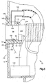
- the walls include a bottom wall 42 ( Fig. 2 ); a front wall 44 ( Fig. 1 ); an opposite back wall (not shown); an inlet end wall 48, and an outlet end wall 50 ( Figs. 2-6 ).
- the inlet end wall 48 of the cabinet 12 supports an inlet hub 60.
- the inlet hub 60 in the illustrated embodiment is a molded plastic member having a cylindrical main body portion 62.
- the outer diameter of the main body portion 62 is selected to fit within the opening 52 in the inlet end wall 48 of the heating cabinet 12.
- the main body portion 62 has a cylindrical inner surface 66 that defines a cylindrical passage 68 extending through the hub 60.
- the size of the passage 68 is selected to accommodate can ends 14 to be dried in the dryer 10.
- An annular mounting flange 70 of the inlet hub 60 extends radially outward from the main body portion 62.
- the mounting flange 70 is secured by fasteners shown schematically at 72 to the inlet end wall 48 of the cabinet 12.
- the inlet hub 60 is secured to the cabinet 12, with the main body portion 62 projecting into the interior of the cabinet 12 through the opening 52 In the inlet end wall 48 of the cabinet.
- the inlet hub 60 includes a support ring 74.
- the support ring 74 extends inward from the main body portion 62 of the inlet hub 60.
- the support ring 74 has an arcuate configuration and is formed as a continuation of a lower circumferential sector of the main body portion 62.
- the inner diameter of the support ring 74 is substantially equal to the outer diameter of the tube 20.
- the main body portion 62 of the inlet hub 60 has a heater inlet opening 80 at or near the top.
- the main body portion 62 has an opening 82 for receiving a retainer or stop member 84, in the form of a stop screw, directly above the support ring 74.
- the outlet hub 90 is similar in configuration to the inlet hub 60.
- the outlet hub 90 is a molded plastic member having a cylindrical main body portion 92.
- the outer diameter of the main body portion 92 is selected to fit within the opening 54 in the outlet end wall 50 of the cabinet 12.
- the main body portion 92 has a cylindrical inner surface 96 that defines a cylindrical exit passage 98 extending through the hub 90.
- the size of the exit passage 98 is selected to accommodate can ends 14 to be dried in the dryer 10.
- An annular mounting flange 100 of the outlet hub 90 extends radially outward from the main body portion 92.
- the mounting flange 100 is secured by fasteners shown schematically at 102 to the outlet end wall 50 of the cabinet 12.
- the outlet hub 90 is secured to the cabinet 12, with the main body portion 92 projecting into the interior of the cabinet through the opening 54 in the outlet end wall 50 of the cabinet.
- the outlet hub 13 includes a support ring 104.
- the support ring 104 extends inward from the main body portion 92 of the outlet hub 90.
- the support ring 104 has an arcuate configuration and is formed as a continuation of a lower circumferential sector of the main body portion 92.
- the inner diameter of the support ring 104 is substantially equal to the outer diameter of the tube 20.
- an outlet end 106 of the tube 20 can be supported on the support ring 104 so that the cylindrical inner surface 28 of the tube forms a continuation of the cylindrical inner surface 96 of the main body portion 92 of the outlet hub 90. Therefore, when a stick of can ends 14 moves through the dryer 10, it can slide smoothly from the tube 20 onto the main body portion 92 of the outlet hub 90.
- the main body portion 92 of the outlet hub 90 has an exhaust opening 108 at or near the top.
- the main body portion 92 has an opening 110 for receiving a retainer or stop member 112 in the form of a stop screw, directly above the support ring 104.
- the inlet end wall 48 of the cabinet 12 supports a sensor 120, at a location above the inlet hub 60.
- the sensor 120 is operative to sense the presence or absence of movement of a stick of can ends 14 through the inlet hub 60.
- the senor 120 is a non-contact sensor, preferably a laser sensor.
- the laser sensor 120 emits a laser beam, shown schematically at 122, that is directed toward the inlet opening of the inlet hub 60.
- the output of the laser sensor 120 is used in controlling operation of the dryer 10, as described below.
- the dryer 10 also includes a heater 130.
- the heater 130 is located inside the heating cabinet 12 and is supported on the inlet hub 60.
- the heater 130 is an electrically powered, open coil heater including a tubular main wall 132 within which are exposed electrical heating coils 134.
- the coils 134 are connected by lead wires 136 with a controllable source of electric current, such as the power and control circuitry 18.
- the main wall 132 of the heater 130 is connected with an outlet wall 138 extending perpendicular to the main wall to form an L-shaped configuration for the heater.
- the outlet wall 138 is secured to the main body portion 62 of the inlet hub 60 in a manner that the heater interior communicates with the heater inlet opening 80 in the inlet hub.
- the dryer 10 includes an exhaust blower or exhaust fan 140.
- the exhaust fan 140 is preferably located inside the heating cabinet 12 and, in the illustrated embodiment, is supported on the bottom wall 42 of the heating cabinet exhausting to an opening (not shown) in the back wall of the cabinet.
- a flexible duct 144 extends between the exhaust fan 140 and the exhaust opening 108 in the outlet hub 90.
- the duct 144 is connected with the outlet hub 90 by a rigid connector tube 146.
- the exhaust fan 140 is an electrically powered device that is operative to draw air from the interior of the outlet hub 90 and deliver it through the duct 144 to the opening in the back wall and thence to atmosphere, in a manner as described below.
- thermocouple 150 is located on the outlet hub 90.
- the thermocouple 150 has a body portion 156 disposed in an opening in the outlet hub 90.
- the thermocouple 150 has a sensor portion 156 that projects upward from the body portion 152, through a slot in the outlet hub 90, into the central passage 98 of the outlet hub.
- the sensor portion 156 of the thermocouple 150 is in the path of movement of the can ends 14 as they are pushed through the outlet hub 90 in a generally horizontal direction.
- the tube 20 defines a generally enclosed space 160 in the heating cabinet 12, through which can ends 14 travel as they move through the dryer 12.
- the inlet end 76 of the tube 20 is supported on the inlet hub 50 for receiving workpieces.
- the inlet end 76 of the tube 20 enables air to flow into the enclosed space 160 inside the tube, from the interior of the heating cabinet 12.
- the inlet end 76 of the tube 20 rests by gravity on the support ring 74 of the inlet hub 60.
- the retainer or stop member 84 is connected with the inlet hub 60, at a location opposite the support ring 74.
- the retainer or stop member 84 is a nylon screw that is screwed into the opening 82 in the main body portion 62 of the inlet hub 60, at a location diametrically opposite the support ring 74 and at the top of the inlet end 76 of the tube 20.
- a different type of retainer or stop member 84 could be used.
- the screw 84 When the screw 84 is in the opening 82, the screw blocks upward movement of the inlet end 76 of the tube 20 off the support ring 74 of the inlet hub 60. When the screw 84 is out of the opening 82, upward movement of the inlet end 76 of the tube 20, off the support ring 74 of the inlet hub 60, is not blocked, and the inlet end of the tube can be lifted upward.
- the outlet end 106 of the tube 20 rests by gravity on the support ring 104 of the outlet hub 90.
- the retainer or stop member 112 is connected with the outlet hub 90, at a location opposite the support ring 104.
- the retainer or stop member 112 is a nylon screw that is screwed into the opening 110 in the main body portion 92 of the outlet hub 90, at a location diametrically opposite the support ring 104 and at above the outlet end 106 of the tube 20.
- a different type of retainer or stop member 112 could be used.
- the screw 112 When the screw 112 is in the opening 110, the screw blocks upward movement of the outlet end 106 of the tube 20 off the support ring 104 of the outlet hub 90.
- the screw 112 When the screw 112 is out of the opening 110, upward movement of the outlet end 106 of the tube 20, off the support ring 104 of the outlet hub 90, is not blocked, and the outlet end of the tube can be lifted upward. As a result, removal of the tube 20 for maintenance and changing of tube sizes is very easy.
- Can ends 14 to be dried are conveyed into the inlet passage 68 of the inlet hub 60 and thence into the inlet end 76 of the tube 20.
- the can ends 14 as they move through the tube 20 are acted upon by an alternating magnetic field generated by the induction coil 22.
- the can ends 14 are heated as a result, and this heat is conducted into the compound on the can ends.
- water is driven out of the compound into the surrounding air within the enclosed space 160 of the tube 20. This water is removed from the tube 20 as follows, to enable more can ends 14 to be dried within the tube.
- the heater cabinet 12 is pressurized (above atmospheric) with heated air from the power and control cabinet 16.
- the fan 30 in the power and control cabinet 16 forces heated air from the power and control cabinet upward through the vent opening 28 in the bottom wall 42 of the heating cabinet 12.
- the air in the heating chamber 40 of the heating cabinet 12, surrounding the tube 20 is pressurized and heated to some extent.
- the exhaust fan 140 in the heating cabinet 12 draws air from the outlet end 106 of the tube 20. This suction creates a flow of air through the tube 20 in a direction from the inlet end 76 of the tube to the outlet end 106 of the tube. As a result, air is drawn into the inlet end 76 of the tube 20, through the heater inlet opening 80, from the interior of the heating cabinet 12.
- air in the prior art dryer described above is typically heated to 40 degrees Celsius, while air with the present dryer 10 is heated to about 60 degrees Celsius.
- heating the preheated air from the interior of the heating cabinet 12 also produces hotter air than does the heating of ambient air. Because the air is heated twice, and to a higher temperature, it is able to absorb more of the moisture in the enclosed space 160 that is driven off from the heated can ends 14.
- 60 degrees is the presently preferred temperature, it is possible to achieve some of the benefits of the heated air, at a reduced level, by heating the air to a temperature of at least 50 degrees Celsius. It is normally preferred that temperatures above about 65 degrees Celsius not be used because they can cause the compound on the can ends 14 to skin over, trapping water within the compound.
- the heater 130 is located Inside the cabinet 12, adjacent the inlet end 76 of the tube 20, the heated air from the heater is ducted directly into the inlet hub 60 and thence into the inlet end of the tube. This configuration minimizes the opportunity for heat loss that might otherwise occur through extensive ductwork or external ductwork or boxes, as in the prior art dryer.
- the can ends 14 slide along the inner surface 96 of the outlet hub 90 and engage the sensor portion 156 of the thermocouple 150 as they do so.
- the sensor portion 156 resiliently or deforms bends from the contact by the can ends 14.
- This direct contact of the can ends 14 with the thermocouple sensor 156 provides improved temperature sensing of the can ends, which always contact the thermocouple by gravity and provide a constant pressure due to design placement, as compared to the overhead sensing that was provided with the prior art dryer in which the thermocouple was subject to installation adjustment and product jams which alter sensitivity.
- the output of the thermocouple 150 is directed to the power and control circuitry 18 and can be used to help control the current flow to the induction coil 22.
- the laser sensor 120 is operative to sense the presence or absence of movement of a stick of can ends 14 through the inlet hub 60.
- the output of the sensor 120 is directed to the power and control circuitry 18. If the sensor 120 senses that the can ends 14 are moving into the dryer 10, the induction coil 22 can be operated to heat and dry the can ends. If, on the other hand, the sensor 120 senses that the stick of can ends is slowed or stopped, for example by a jam or by simply a lack of workpieces coming into the dryer 10, then the induction coil 22 can be controlled to reduce or eliminate current flow through the induction coil. Because the laser sensor 120 is a non-contact sensor, it is not affected by jams or out of position can ends 14 in a stick. In comparison to the prior art rotating wheel sensor, therefore, the laser sensor 120 of the present dryer 10 is a significant improvement.
Landscapes
- Physics & Mathematics (AREA)
- Electromagnetism (AREA)
- Engineering & Computer Science (AREA)
- Power Engineering (AREA)
- Life Sciences & Earth Sciences (AREA)
- Microbiology (AREA)
- Mechanical Engineering (AREA)
- General Engineering & Computer Science (AREA)
- Drying Of Solid Materials (AREA)
- Heat Treatment Of Articles (AREA)
Claims (6)
- Appareil de chauffage par induction pour chauffer des pièces à travailler se déplaçant à travers ledit appareil, comprenant un logement (12), un tube (20) dans ledit logement (12) définissant un espace généralement clos (160) dans ledit logement à travers lequel les pièces à travailler (14) cheminent au fur et à mesure qu'elles se déplacent à travers ledit appareil, ledit tube (20) ayant une extrémité d'admission (76) pour recevoir des pièces à travailler (14), et une extrémité de sortie (106) pour décharger des pièces à travailler (14), un serpentin d'induction (22) pour chauffer les pièces à travailler (14) au fur et à mesure qu'elles se déplacent à travers ledit espace clos (160), et un ventilateur (140), caractérisé en ce que l'appareil comprend une admission d'air (80) dans ledit tube (20) pour permettre à l'air de s'écouler dans ledit espace clos (160) et une sortie d'air (108) dans ledit tube (20) pour permettre à l'air de s'écouler hors dudit espace clos (160) à l'extérieur dudit logement (12), et le ventilateur (140) étant opérationnel pour déplacer l'air à travers ledit espace clos (160) entre ladite admission d'air (80) et ladite sortie d'air (108), et en ce que ladite admission d'air dans ledit tube (20) permet à l'air de s'écouler de l'intérieur dudit logement dans ledit espace clos (160).
- Appareil selon la revendication 1, dans lequel ledit ventilateur est un ventilateur d'aspiration (140) raccordé à ladite sortie d'air (140) et opérationnel pour aspirer l'air à travers ledit espace clos (160).
- Appareil selon la revendication 2, dans lequel ledit logement (12) est pressurisé avec de l'air chauffé des circuits de puissance et de commande associés audit serpentin d'induction (22).
- Appareil selon la revendication 3, dans lequel ledit ventilateur (140) est situé dans le trajet de l'écoulement d'air de ladite sortie d'air (108) et est opérationnel pour aspirer l'air hors de ladite sortie d'air (108).
- Appareil selon l'une quelconque des revendications précédentes, comprenant en outre un élément chauffant (130) situé à l'intérieur dudit logement au niveau de ladite admission d'air (106) dudit tube (20) pour chauffer l'air s'écoulant dans ledit tube (20).
- Appareil selon l'une quelconque des revendications précédentes, dans lequel ledit logement (12) a des parois d'extrémité opposées (48, 50) pour soutenir ledit tube (20), chacune desdites parois d'extrémité (48, 50) ayant un membre d'appui (74, 104) sur lequel une extrémité respective dudit tube (20) repose pour bloquer le mouvement vers le bas de ladite extrémité du tube (76, 106), chacune desdites parois d'extrémité (48, 50) ayant un membre de butée (84, 112) raccordé d'une manière amovible à ladite paroi d'extrémité (48, 50) à un emplacement au-dessus de ladite extrémités du tube (76, 106) pour bloquer le mouvement vers le haut de ladite extrémité du tube (76, 106) ledit tube (20) pouvant être retiré dudit logement (12) en le soulevant vers le haut hors dudit logement (12).
Priority Applications (1)
| Application Number | Priority Date | Filing Date | Title |
|---|---|---|---|
| EP11168987.3A EP2365731B1 (fr) | 2002-12-09 | 2003-12-09 | Appareil de séchage à induction |
Applications Claiming Priority (3)
| Application Number | Priority Date | Filing Date | Title |
|---|---|---|---|
| US43193802P | 2002-12-09 | 2002-12-09 | |
| US431938P | 2002-12-09 | ||
| PCT/US2003/038942 WO2004054323A2 (fr) | 2002-12-09 | 2003-12-09 | Dispositif de sechage a induction |
Related Child Applications (2)
| Application Number | Title | Priority Date | Filing Date |
|---|---|---|---|
| EP11168987.3A Division EP2365731B1 (fr) | 2002-12-09 | 2003-12-09 | Appareil de séchage à induction |
| EP11168987.3A Division-Into EP2365731B1 (fr) | 2002-12-09 | 2003-12-09 | Appareil de séchage à induction |
Publications (2)
| Publication Number | Publication Date |
|---|---|
| EP1570709A2 EP1570709A2 (fr) | 2005-09-07 |
| EP1570709B1 true EP1570709B1 (fr) | 2016-05-25 |
Family
ID=32507828
Family Applications (2)
| Application Number | Title | Priority Date | Filing Date |
|---|---|---|---|
| EP03812848.4A Expired - Lifetime EP1570709B1 (fr) | 2002-12-09 | 2003-12-09 | Dispositif de sechage a induction |
| EP11168987.3A Expired - Lifetime EP2365731B1 (fr) | 2002-12-09 | 2003-12-09 | Appareil de séchage à induction |
Family Applications After (1)
| Application Number | Title | Priority Date | Filing Date |
|---|---|---|---|
| EP11168987.3A Expired - Lifetime EP2365731B1 (fr) | 2002-12-09 | 2003-12-09 | Appareil de séchage à induction |
Country Status (4)
| Country | Link |
|---|---|
| US (4) | US7432480B2 (fr) |
| EP (2) | EP1570709B1 (fr) |
| AU (1) | AU2003296325A1 (fr) |
| WO (1) | WO2004054323A2 (fr) |
Families Citing this family (11)
| Publication number | Priority date | Publication date | Assignee | Title |
|---|---|---|---|---|
| EP1570709B1 (fr) | 2002-12-09 | 2016-05-25 | Nordson Corporation | Dispositif de sechage a induction |
| EP1826516A1 (fr) * | 2006-02-28 | 2007-08-29 | Rösler Italiana S.r.L. | Dispositif de séchage de pièces métalliques |
| CN102778117B (zh) * | 2012-08-04 | 2013-06-05 | 朱树伟 | 一种干燥设备及设计方法 |
| US9883551B2 (en) * | 2013-03-15 | 2018-01-30 | Silgan Containers Llc | Induction heating system for food containers and method |
| US10237924B2 (en) * | 2013-03-15 | 2019-03-19 | Silgan Containers Llc | Temperature detection system for food container induction heating system and method |
| WO2015164174A1 (fr) | 2014-04-24 | 2015-10-29 | Silgan Containers Llc | Système de chauffage par induction d'un récipient alimentaire possédant une puissance basée sur la surveillance de la létalité microbienne |
| JP2016189263A (ja) * | 2015-03-30 | 2016-11-04 | トヨタ自動車株式会社 | 誘導加熱装置 |
| CN106679377B (zh) * | 2016-11-08 | 2018-12-18 | 南通德和布业有限公司 | 一种摆动式快速吸湿机构 |
| CA3137103A1 (fr) * | 2019-04-19 | 2020-10-22 | Photex Inc. | Systeme et procede pour le durcissement d'un interieur de boite |
| US12280396B2 (en) | 2019-04-19 | 2025-04-22 | Photex Inc. | Narrowband can manufacturing |
| WO2025212177A1 (fr) | 2024-04-03 | 2025-10-09 | Nordson Corporation | Agencements et procédés de séchage par induction |
Family Cites Families (12)
| Publication number | Priority date | Publication date | Assignee | Title |
|---|---|---|---|---|
| US2716695A (en) * | 1952-04-12 | 1955-08-30 | Int Harvester Co | Induction heating unit |
| CA868884A (en) * | 1968-08-21 | 1971-04-20 | Pulp And Paper Research Institute Of Canada | Method for the production of activated carbon |
| US3912846A (en) * | 1971-08-09 | 1975-10-14 | Nippon Kokan Kk | Apparatus for manufacturing steel plates coated with aluminium powder |
| EP0056974B1 (fr) * | 1981-01-23 | 1985-06-19 | Kabushiki Kaisha Toshiba | Appareil de cuisson composé |
| JPH0679751B2 (ja) * | 1986-06-12 | 1994-10-12 | 富士電機株式会社 | 温間鍛造用加熱装置 |
| US5483042A (en) * | 1990-06-04 | 1996-01-09 | Nordson Corporation | Magnetic separator |
| US5529703A (en) * | 1990-06-04 | 1996-06-25 | Nordson Corporation | Induction dryer and magnetic separator |
| US5821504A (en) * | 1990-06-04 | 1998-10-13 | Nordson Corporation | Induction heating system for 360° curing of can body coatings |
| US5128172A (en) * | 1990-10-12 | 1992-07-07 | Whittick Thomas E | Continuous coating process with inductive heating |
| DE69619155T2 (de) * | 1995-05-10 | 2002-09-26 | Nordson Corp., Westlake | Induktionsheizsystem für Härtung über 360 Grad von Beschichtungen von Dosenkörpern |
| FR2746176B1 (fr) * | 1996-03-14 | 1998-04-10 | Dispositif d'injection de gaz non oxydant a l'interieur d'un four | |
| EP1570709B1 (fr) | 2002-12-09 | 2016-05-25 | Nordson Corporation | Dispositif de sechage a induction |
-
2003
- 2003-12-09 EP EP03812848.4A patent/EP1570709B1/fr not_active Expired - Lifetime
- 2003-12-09 WO PCT/US2003/038942 patent/WO2004054323A2/fr not_active Ceased
- 2003-12-09 AU AU2003296325A patent/AU2003296325A1/en not_active Abandoned
- 2003-12-09 US US10/527,860 patent/US7432480B2/en not_active Expired - Lifetime
- 2003-12-09 EP EP11168987.3A patent/EP2365731B1/fr not_active Expired - Lifetime
-
2008
- 2008-08-21 US US12/195,626 patent/US8258445B2/en not_active Expired - Fee Related
-
2012
- 2012-08-07 US US13/568,448 patent/US8796601B2/en not_active Expired - Lifetime
-
2014
- 2014-06-06 US US14/298,345 patent/US9814103B2/en not_active Expired - Fee Related
Also Published As
| Publication number | Publication date |
|---|---|
| EP2365731B1 (fr) | 2014-07-23 |
| US20120291253A1 (en) | 2012-11-22 |
| EP2365731A2 (fr) | 2011-09-14 |
| EP2365731A3 (fr) | 2013-11-20 |
| US20140284322A1 (en) | 2014-09-25 |
| EP1570709A2 (fr) | 2005-09-07 |
| WO2004054323A2 (fr) | 2004-06-24 |
| US7432480B2 (en) | 2008-10-07 |
| AU2003296325A8 (en) | 2004-06-30 |
| US20060151479A1 (en) | 2006-07-13 |
| US20080302786A1 (en) | 2008-12-11 |
| WO2004054323A3 (fr) | 2004-08-26 |
| US9814103B2 (en) | 2017-11-07 |
| US8258445B2 (en) | 2012-09-04 |
| AU2003296325A1 (en) | 2004-06-30 |
| US8796601B2 (en) | 2014-08-05 |
Similar Documents
| Publication | Publication Date | Title |
|---|---|---|
| US9814103B2 (en) | Induction dryer | |
| EP0558151B1 (fr) | Four | |
| US7121821B2 (en) | Device for heating preforms provided with supporting ring | |
| US5908000A (en) | Heat curing system for silk screen printing press | |
| JP3844306B2 (ja) | スクリューコンベヤのばら材を熱処理する装置 | |
| US6925777B2 (en) | Method and a machine for heat-shrinking heat-shrink sleeves engaged individually on articles such as bottles | |
| GB2357827A8 (en) | Dryer assembly | |
| KR920017201A (ko) | 종형 열처리장치 | |
| EP0742680B9 (fr) | Système de chauffage par induction par le durcissement sur 360 degrès du revêtement d'un corps de boîte | |
| US20100083525A1 (en) | Device and method for heat-treating a pourable plant product | |
| US20190161855A1 (en) | Method for coating plastic receptacles | |
| US4014286A (en) | Hot product marking system | |
| KR101123420B1 (ko) | 용기용 라벨 부착장치 | |
| US20200367535A1 (en) | Continuous-flow treatment system for solid food and animal feed and other bulk materials, having a heat treatment device for thermal continuous-flow treatment | |
| RU2094717C1 (ru) | Сушилка для термопластичных материалов | |
| JP2002102314A (ja) | トンネル型乾燥滅菌機 | |
| CN1739407B (zh) | 具有连续传送带的热调节系统 | |
| CN107305090A (zh) | 一种快速烘干机 | |
| KR100211282B1 (ko) | 입자매체용 건조 및 냉각처리장치 | |
| CN210892615U (zh) | 一种自动充装烘干装置 | |
| JPH0718192U (ja) | 加熱装置 | |
| CN211168505U (zh) | 一种传输机 | |
| KR0138300Y1 (ko) | 반도체 패키지의 마킹잉크 말림장치 | |
| JPS6341041Y2 (fr) | ||
| CN119755910A (zh) | 一种粮仓环境温湿度调节系统及其调节方法 |
Legal Events
| Date | Code | Title | Description |
|---|---|---|---|
| PUAI | Public reference made under article 153(3) epc to a published international application that has entered the european phase |
Free format text: ORIGINAL CODE: 0009012 |
|
| 17P | Request for examination filed |
Effective date: 20050606 |
|
| AK | Designated contracting states |
Kind code of ref document: A2 Designated state(s): AT BE BG CH CY CZ DE DK EE ES FI FR GB GR HU IE IT LI LU MC NL PT RO SE SI SK TR |
|
| AX | Request for extension of the european patent |
Extension state: AL LT LV MK |
|
| DAX | Request for extension of the european patent (deleted) | ||
| RBV | Designated contracting states (corrected) |
Designated state(s): DE GB |
|
| 17Q | First examination report despatched |
Effective date: 20090616 |
|
| GRAP | Despatch of communication of intention to grant a patent |
Free format text: ORIGINAL CODE: EPIDOSNIGR1 |
|
| INTG | Intention to grant announced |
Effective date: 20151208 |
|
| GRAS | Grant fee paid |
Free format text: ORIGINAL CODE: EPIDOSNIGR3 |
|
| GRAA | (expected) grant |
Free format text: ORIGINAL CODE: 0009210 |
|
| AK | Designated contracting states |
Kind code of ref document: B1 Designated state(s): DE GB |
|
| REG | Reference to a national code |
Ref country code: GB Ref legal event code: FG4D |
|
| REG | Reference to a national code |
Ref country code: DE Ref legal event code: R096 Ref document number: 60348987 Country of ref document: DE |
|
| REG | Reference to a national code |
Ref country code: DE Ref legal event code: R097 Ref document number: 60348987 Country of ref document: DE |
|
| PLBE | No opposition filed within time limit |
Free format text: ORIGINAL CODE: 0009261 |
|
| STAA | Information on the status of an ep patent application or granted ep patent |
Free format text: STATUS: NO OPPOSITION FILED WITHIN TIME LIMIT |
|
| 26N | No opposition filed |
Effective date: 20170228 |
|
| PGFP | Annual fee paid to national office [announced via postgrant information from national office to epo] |
Ref country code: GB Payment date: 20221222 Year of fee payment: 20 Ref country code: DE Payment date: 20221213 Year of fee payment: 20 |
|
| P01 | Opt-out of the competence of the unified patent court (upc) registered |
Effective date: 20230530 |
|
| REG | Reference to a national code |
Ref country code: DE Ref legal event code: R071 Ref document number: 60348987 Country of ref document: DE |
|
| REG | Reference to a national code |
Ref country code: GB Ref legal event code: PE20 Expiry date: 20231208 |
|
| PG25 | Lapsed in a contracting state [announced via postgrant information from national office to epo] |
Ref country code: GB Free format text: LAPSE BECAUSE OF EXPIRATION OF PROTECTION Effective date: 20231208 |
|
| PG25 | Lapsed in a contracting state [announced via postgrant information from national office to epo] |
Ref country code: GB Free format text: LAPSE BECAUSE OF EXPIRATION OF PROTECTION Effective date: 20231208 |