EP1570219B1 - Rippe und block für einen heizkörper - Google Patents
Rippe und block für einen heizkörper Download PDFInfo
- Publication number
- EP1570219B1 EP1570219B1 EP03770806A EP03770806A EP1570219B1 EP 1570219 B1 EP1570219 B1 EP 1570219B1 EP 03770806 A EP03770806 A EP 03770806A EP 03770806 A EP03770806 A EP 03770806A EP 1570219 B1 EP1570219 B1 EP 1570219B1
- Authority
- EP
- European Patent Office
- Prior art keywords
- folding
- radiator
- rib
- foldings
- external
- Prior art date
- Legal status (The legal status is an assumption and is not a legal conclusion. Google has not performed a legal analysis and makes no representation as to the accuracy of the status listed.)
- Expired - Lifetime
Links
Images


Classifications
-
- F—MECHANICAL ENGINEERING; LIGHTING; HEATING; WEAPONS; BLASTING
- F28—HEAT EXCHANGE IN GENERAL
- F28D—HEAT-EXCHANGE APPARATUS, NOT PROVIDED FOR IN ANOTHER SUBCLASS, IN WHICH THE HEAT-EXCHANGE MEDIA DO NOT COME INTO DIRECT CONTACT
- F28D1/00—Heat-exchange apparatus having stationary conduit assemblies for one heat-exchange medium only, the media being in contact with different sides of the conduit wall, in which the other heat-exchange medium is a large body of fluid, e.g. domestic or motor car radiators
- F28D1/02—Heat-exchange apparatus having stationary conduit assemblies for one heat-exchange medium only, the media being in contact with different sides of the conduit wall, in which the other heat-exchange medium is a large body of fluid, e.g. domestic or motor car radiators with heat-exchange conduits immersed in the body of fluid
- F28D1/03—Heat-exchange apparatus having stationary conduit assemblies for one heat-exchange medium only, the media being in contact with different sides of the conduit wall, in which the other heat-exchange medium is a large body of fluid, e.g. domestic or motor car radiators with heat-exchange conduits immersed in the body of fluid with plate-like or laminated conduits
- F28D1/0308—Heat-exchange apparatus having stationary conduit assemblies for one heat-exchange medium only, the media being in contact with different sides of the conduit wall, in which the other heat-exchange medium is a large body of fluid, e.g. domestic or motor car radiators with heat-exchange conduits immersed in the body of fluid with plate-like or laminated conduits the conduits being formed by paired plates touching each other
- F28D1/0325—Heat-exchange apparatus having stationary conduit assemblies for one heat-exchange medium only, the media being in contact with different sides of the conduit wall, in which the other heat-exchange medium is a large body of fluid, e.g. domestic or motor car radiators with heat-exchange conduits immersed in the body of fluid with plate-like or laminated conduits the conduits being formed by paired plates touching each other the plates having lateral openings therein for circulation of the heat-exchange medium from one conduit to another
- F28D1/0333—Heat-exchange apparatus having stationary conduit assemblies for one heat-exchange medium only, the media being in contact with different sides of the conduit wall, in which the other heat-exchange medium is a large body of fluid, e.g. domestic or motor car radiators with heat-exchange conduits immersed in the body of fluid with plate-like or laminated conduits the conduits being formed by paired plates touching each other the plates having lateral openings therein for circulation of the heat-exchange medium from one conduit to another the plates having integrated connecting members
Definitions
- the rib and the block for a radiator are applicable in the field of construction of heating appliances.
- a radiator block for heating of rooms is known [EPA0556433A1], which consists of many ribs, a pair of which forms a radiator element.
- a complete heating appliance such as a radiator
- there is hot liquid inside the radiator elements which is heated by an electric resistance heater.
- Known ribs have two typical holes and one typical joining profile, as well as a first folding and a second folding for decreasing the heating of the external peripheral surface of the radiator and for simultaneous increase of the heat-transfer efficiency.
- the ribs have a third intermediate and a fourth external folding, which ends in a reversed fifth folding.
- the various foldings of the two ribs, forming the radiator element separate a channel-like section which decreases the temperature of the block surface and especially of the surfaces formed by the external foldings.
- the five foldings serve to avoid the formation of sharp edges in the slots of the obtained external surface.
- the block of known ribs [EPA0556433A1] is provided with a lateral external surface, which is absolutely flat. During operation its safety temperature is lowered, which ensures safety in case it is touched during exploitation.
- a disadvantage of the known rib is the existence of two unsafe zones in the upper and lower part of each rib, respectively of the whole block, due to the vertically opened channels formed in the rib.
- a series of dangerous for the user sharp edges exist in the lower unsafe zone and the users might be wounded in case of contact with them.
- the open channel in the upper unsafe zone, and in particular, the surface of the heat-conducting channel, where the temperature is highest, may easily be reached by hand, especially of a child. Such contact causes painful and harmful burnings of the body.
- the lid is provided with holes which are as large as possible, but the danger of uncontrolled access of children's hands to the surface of the heat-conducting channel is not completely eliminated. Due to all of the above, the safety and the velocity of heat transfer of the known radiator rib and block are decreased. Because of the strict rules according to the accepted standards for the surface temperature, the enlargement of the heat transfer surface is connected with the enlargement of the dimensions of the known rib, and respectively, of the radiator block, which leads to consumption of more materials, increase of weight, inconvenience in exploitation, and as a final result, to increase of its cost.
- the object of the present invention is to provide a rib and a block for a radiator with increased operational safety and heat transfer velocity and with a reduced consumption of materials.
- a rib consisting of a typical upper hole, a typical lower hole and a typical joining profile, as well as a first and a second internal folding, a third intermediate and a fourth external folding, which ends in a reversed fifth folding.
- the fourth external folding and the fifth reverse folding extend from below to the end of their respective chamfers, and at the upper side of the rib, together with the second and the third folding, they connect its two vertical walls by means of two chamfers.
- spherical concavities Centrally in relation to the upper hole, on its both sides, and above, on the surface of the second internal folding and the third intermediate folding, there are spherical concavities, and on both sides of the lower hole there are similar spherical concavities.
- a second radiator block is also provided and it consists of N radiator elements, each formed by a pair of ribs, which are the same as the ribs described above.
- the advantage of the rib and the block for radiators is that they have increased operational safety and heat transfer velocity.
- Another advantage is that the rib has a simplified technology of producing and reduced material consumption.
- the rib shown on fig. 1 to fig. 9 comprises a typical upper hole 1.1, a typical lower hole 1.2 and a typical joining profile 2, as well as a first internal folding 3 and a second 4 internal folding, a third intermediate 5 and a fourth external 6 folding, which ends in a fifth reversed folding 7.
- the fourth external folding 6 and the fifth reverse folding 7 extend from below to the end of their respective chamfers 8, and at the upper side of the rib, together with the second 4 and third 5 folding, they connect its two vertical walls by means of two chamfers 9.
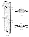
- the radiator element 12 shown on fig. 10 to fig. 12 is formed by a pair of ribs, which are the same as the rib shown on fig. 1.
- the radiator block shown on fig. 13 consists of N radiator elements, such as the radiator elements shown on fig. 10.
- the rib (shown on fig. 1 - 9) is produced with die-stamping tools by means of cold drawing and cutting of the holes 1.1 and 1.2, as well as cutting of the external contour through consecutive operations until the rib takes up its final completed form, such as the form shown on the figures.
- the radiator element (fig. 10, 11, 12) consists of two ribs, exactly fixed opposite one another, thus forming two sticking zones. The first sticking zone is in the middle of the typical joining profile 2, and the second zone is along the folding 3.
- the first operation is spot welding performed in the middle of the typical profile 2.
- the second operation consists of applying a roll-welding seam along the contour of the typical profile 2 within the space of the folding 3.
- closure of the volume, formed between the two opposite typical profiles 2 of the pair of ribs is achieved (fig. 12).
- the spherical concavities 10 and 11 provide the necessary space for the passage of a welding roll, whose diameter is such that it ensures the necessary resource for mass production.
- the edges formed at the transitions between the spherical concavities 10 and 11 and the foldings 4 and 5 strengthen the structure of the rib.
- the radiator block (fig. 13) is assembled by welding the radiator elements within the zone surrounding the typical holes 1.1 and 1.2, thus achieving a uniform hermetically sealed volume in which the heat transferring fluid flows (not shown on figures).
- the first zone extends along the axis of the holes 1.1.
- the second zone encompasses the spaces, closed by the typical joining profiles 2 of all radiator elements.
- the third zone encompasses the space along the axis of the holes 1.2.
- the heat transferring fluid takes up the volume of the second and the third zone and reaches up to the level of the first zone.
- An electric resistance heating element (not shown on the figures) is also arranged in the third zone and it heats up the heat transferring fluid. As a result, the heat transferring fluid expands and this expansion is received in the volume of the first zone (along the axis of the holes 1.1).
- each heating radiator consisting of the ribs, respectively, of the block according to the invention is able to transfer a maximum quantity of heat. This is due to the achieved provision of high temperature over a large heating and heat-transfer surface of the block.
- the high surface temperature is dangerous for the users, but the rib, respectively, the block provide the possibility of circulation of the hot heat-transferring fluid only within the radiator elements.
- the heat is transferred to the walls of the channels, formed by the typical joining profiles 2, opposite to one another, which for their part consequently transfer heat to foldings 3, 4, 5, 6, 7.
- the air particles that are in direct contact with the hot foldings surfaces get heated, and then, through convection, they transport the absorbed heat into the room. As it is shown on fig.
- the typical joining profile and the folding 3 transfer heat to the surrounding environment with their external surfaces, whereas the foldings 4, 5, 6 and 7, the spherical concavities 10 and 11 and the chamfers 8 and 9 transfer the heat with their both surfaces.
- the overall heat-transferring surface is considerably increased and the temperature of the folding 6, external to the radiator block, is decreased. It is namely the folding 6 that is accessible for touching, but due to the intensive heat transfer, its temperature is not dangerous for humans.
- the oppositely arranged foldings 4, 5, 6, 7 of the radiator elements form consecutively arranged vertical structures, thus increasing the convection (chimney effect).
- the radiator block ensures the free penetration of cold air into its lower part as well as the leakage of the heated air through the slots formed by the opposing foldings 7 in the radiator elements and the opposing foldings 5 between the adjacent radiator elements.
- concentration of high temperatures inside the radiator block is achieved, and in particular, in the field of the typical profile 2 and the folding 3.
- the heat transfer is increased thanks to the two heat transferring sides of the foldings 4, 5, 6, 7 and the vertical structures, which increase the convective flows.
- the temperature of the surface of the folding 6 is lower.
- the radiator block has a uniform flat lateral and upper surface, formed by the consecutively repeating foldings 6 of the ribs, connected in their upper ends with the chamfer 9 and ending at their lower ends with the chamfer 8, furrowed by the slots formed by the distances between the foldings 7 in the radiator element and the distances between the foldings 5 of two adjacent radiator elements, whereas both distances are equal.
- all edges of the slots are rounded, especially in the transition point between the folding 5 and 6, and in the transition point between the folding 6 and 7. This provides safety in case of touching because the size of the slots does not allow the penetration of a hand, including a child's hand, to the hot internal surfaces. At the same time, the free movement of airflow is not restricted.
- the design of the rib and the radiator element is such that a finished construction of a radiator block is obtained only through multiplication of the rib, without any need of additional elements, such as lids, screens, baffles, gratings etc.
- the area is increased owing to the bilateral heat transfer of the foldings 4, 5, 6 and 7, the chamfers 8 and 9, and of the channel-shaped structures. In this way, the convective flow and, as a result, the heating power, are increased, thus allowing the faster heating of the room.
Landscapes
- Engineering & Computer Science (AREA)
- Physics & Mathematics (AREA)
- Thermal Sciences (AREA)
- Mechanical Engineering (AREA)
- General Engineering & Computer Science (AREA)
- Domestic Hot-Water Supply Systems And Details Of Heating Systems (AREA)
- Central Heating Systems (AREA)
- Cooling Or The Like Of Electrical Apparatus (AREA)
Claims (5)
- Rippe für die Herstellung eines Heizkörperelements, bestehend aus zwei Rippen, genau gegeneinander stehend, wobei zwei anliegende Bereiche und ein Durchflusskanal für das wärmeübertragende Medium dazwischen entstehen; welche Rippe aus einer oberen Bohrung (1.1), unteren Bohrung (1.2) Anschlussprofil (2), das die Kanalwand für das wärmeübertragende Medium bildet, sowie aus erster (3) und zweiter (4) Innenfalzung, dritter Mittelfalzung (5) und vierter Außenfalzung (6), die an der fünften Wendefalzung abschließt (7), welche vierte Außenfalzung (6) zusammen mit den vierten Außenfalzungen (6) der benachbarten Rippen eine flache Seitenfläche beim Zusammenbau für die Herstellung des Heizkörperelements bildet und aus erstem Anliegbereich, gebildet in der Mitte des Anschlussprofils (2), zweitem Anliegbereich, gebildet entlang der ersten Innenfalzung (3), besteht, wobei die Wärme vom Anschlussprofil (2) und der Reihe nach zur ersten Innenfalzung (3), zweiten Innenfalzung (4), dritten Zwischenfalzung (5), vierten Außenfalzung (6) und fünften Wendefalzung (7) übertragen wird, wobei die zweite Innenfalzung (4), dritte Mittelfalzung (5), vierte Außenfalzung (6) und fünfte Wendefalzung (7) Wärme an das Umfeld mit ihren beiden Flächen abgeben, gekennzeichnet dadurch, dass die Außenfalzung (6) und die Wendefalzung (7) entlang der beiden gegenüberliegenden senkrechten Rippenwänden bis zum Rippenunterteil verlaufen, wo sie mit zwei Abrundungen (8) an jeder gegenüberliegenden unteren Rippenecke enden, und die Mittel-, Außen- und Wendefalzung (5, 6 und 7) bis zum oberen Rippenteil verlaufen und zwei Abrundungen (9), angeordnet an den beiden gegenüberliegenden oberen Rippenecken bilden, wobei mittig zu der oberen Bohrung (1.1), an ihren beiden Seiten und von oben, auf den Oberflächen der zweiten Falzung (4) und der dritten Falzung (5) drei kugelförmige Konkavitäten liegen (11), und an den beiden Seiten der unteren Bohrung (1.2) zwei ähnliche kugelförmige Konkavitäten (11) auf den Oberflächen der zweiten Falzung (4) und der dritten Falzung (5) liegen, wobei die kugelförmigen Konkavitäten (10, 11) den erforderlichen Raum für den Durchgang der Schweißelektrode entlang des zweiten Anliegbereichs gewährleisten, damit das Heizkörperelement montiert wird.
- Rippe für die Herstellung eines Heizkörperelements, nach Anspruch 1, gekennzeichnet dadurch, dass die Kanten zwischen den Falzungen (5) und (6) und zwischen den Falzungen (6) und (7) abgerundet sind.
- Heizkörperelement, gekennzeichnet dadurch, dass es aus zwei Rippen nach Anspruch 1 besteht, genau gegeneinander stehend und zwei anliegende Bereiche bildend, wobei die gegenüber angeordneten Falzungen (4,5,6 und 7) der beiden Rippen nacheinander angeordnete senkrechte Strukturen für die Erhöhung der Konvektion und der Geschwindigkeit der Wärmeübertragung gestalten.
- Block für Heizkörper, bestehend aus N-Stück Heizkörperelementen, gekennzeichnet dadurch, dass die Heizkörperelemente (12) nach Anspruch 3 ausgeführt sind, wobei die gegeneinander angeordneten Falzungen (4, 5) der Heizkörperelemente nacheinander angeordnete senkrechte Strukturen für die Erhöhung der Konvektion und der Geschwindigkeit der Wärmeübertragung gestalten.
- Block für Heizkörper nach Anspruch 4, gekennzeichnet dadurch, dass die Schlitze zwischen den Falzungen (7) in einem Heizkörperelement (12) und die Schlitze zwischen den Falzungen (5) in zwei benachbarten Heizkörperelementen (12) gleich sind und deren Breite so ausgelegt, dass sie das Eingreifen mit der Hand bis zu den heißen Innenflächen des Heizkörperblocks nicht zulässt.
Applications Claiming Priority (3)
| Application Number | Priority Date | Filing Date | Title |
|---|---|---|---|
| BG107388A BG64716B1 (bg) | 2002-12-13 | 2002-12-13 | Ребро и блок за радиатор |
| BG10738802 | 2002-12-13 | ||
| PCT/BG2003/000039 WO2004055461A1 (en) | 2002-12-13 | 2003-10-30 | Rib and block for a radiator |
Publications (2)
| Publication Number | Publication Date |
|---|---|
| EP1570219A1 EP1570219A1 (de) | 2005-09-07 |
| EP1570219B1 true EP1570219B1 (de) | 2007-01-10 |
Family
ID=3928649
Family Applications (1)
| Application Number | Title | Priority Date | Filing Date |
|---|---|---|---|
| EP03770806A Expired - Lifetime EP1570219B1 (de) | 2002-12-13 | 2003-10-30 | Rippe und block für einen heizkörper |
Country Status (10)
| Country | Link |
|---|---|
| US (1) | US7182123B2 (de) |
| EP (1) | EP1570219B1 (de) |
| CN (1) | CN100529633C (de) |
| AU (1) | AU2003280237A1 (de) |
| BG (1) | BG64716B1 (de) |
| DE (1) | DE60311144T2 (de) |
| EA (1) | EA006796B1 (de) |
| ES (1) | ES2279181T3 (de) |
| PT (1) | PT1570219E (de) |
| WO (1) | WO2004055461A1 (de) |
Families Citing this family (4)
| Publication number | Priority date | Publication date | Assignee | Title |
|---|---|---|---|---|
| ITUD20060279A1 (it) * | 2006-12-29 | 2008-06-30 | De Longhi Spa | Modulo radiante per un dispositivo di riscaldamento per ambienti e procedimento per realizzare tale modulo radiante |
| US8929805B2 (en) | 2007-10-30 | 2015-01-06 | Nationz Technologies Inc. | System, method, and device for radio frequency communication |
| ITUD20070242A1 (it) * | 2007-12-21 | 2009-06-22 | De Longhi Spa | Modulo radiante per un'apparecchiatura di riscaldamento e relativo procedimento per realizzare tale modulo radiante |
| US12092821B2 (en) * | 2019-02-13 | 2024-09-17 | Kyocera Corporation | Optical component, image display device using same, and head-up display |
Family Cites Families (14)
| Publication number | Priority date | Publication date | Assignee | Title |
|---|---|---|---|---|
| US692365A (en) * | 1898-02-23 | 1902-02-04 | Clarence E Safford | Sheet-metal radiator. |
| US787845A (en) * | 1903-12-21 | 1905-04-18 | William R Kinnear | Sheet-metal radiator. |
| US1975957A (en) * | 1934-04-07 | 1934-10-09 | Walter E Kuenstler | Radiator |
| US2651506A (en) * | 1949-03-24 | 1953-09-08 | Lehmann Ernst | Radiator |
| IT7420683U1 (it) * | 1974-02-01 | 1975-08-01 | Fond F Lli Perani S P A | Radiatore per impianti di riscaldamento ad elementi affiancati formanti dei condotti a camino per la circolazione dell'aria |
| DE2530260A1 (de) | 1975-07-07 | 1977-01-27 | Interelba Dr L A Mancini | Radiator |
| GB2118706B (en) * | 1982-03-11 | 1986-08-06 | Roger Conway Edmon Pallemaerts | Radiators for space heating |
| IT226255Z2 (it) * | 1992-02-18 | 1997-06-02 | Miralfin Srl | Struttura di radiatore particolarmente per il riscaldamento di locali |
| CN2127782Y (zh) * | 1992-06-22 | 1993-03-03 | 中国科学院工程热物理研究所 | 原表面全逆流式热交换器 |
| IT236601Y1 (it) * | 1995-01-20 | 2000-08-17 | Miralfin Srl | Struttura di radiatore particolarmente per il riscaldamentodi locali |
| IT241445Y1 (it) | 1996-03-22 | 2001-05-09 | Laminox Srl | Radiatore ad olio capace di mantenere i propri bordi esterni aridotta temperatura |
| IT243920Y1 (it) * | 1998-04-07 | 2002-03-06 | Laminox S R L | Radiatore elettrico ad olio per il riscaldamento di ambienti |
| ITMI981314A1 (it) | 1998-06-10 | 1999-12-10 | De Longhi Spa | Radiatore di tipo mobile a funzionamento indipendente e procedimento per la sua realizzazione |
| IT1308708B1 (it) * | 1999-02-17 | 2002-01-10 | De Longhi Spa | Radiatore di tipo mobile a funzionamento indipendente |
-
2002
- 2002-12-13 BG BG107388A patent/BG64716B1/bg unknown
-
2003
- 2003-10-30 DE DE60311144T patent/DE60311144T2/de not_active Expired - Lifetime
- 2003-10-30 US US10/533,002 patent/US7182123B2/en not_active Expired - Fee Related
- 2003-10-30 CN CNB2003801038025A patent/CN100529633C/zh not_active Expired - Fee Related
- 2003-10-30 EA EA200500797A patent/EA006796B1/ru not_active IP Right Cessation
- 2003-10-30 WO PCT/BG2003/000039 patent/WO2004055461A1/en not_active Ceased
- 2003-10-30 AU AU2003280237A patent/AU2003280237A1/en not_active Abandoned
- 2003-10-30 ES ES03770806T patent/ES2279181T3/es not_active Expired - Lifetime
- 2003-10-30 EP EP03770806A patent/EP1570219B1/de not_active Expired - Lifetime
- 2003-10-30 PT PT03770806T patent/PT1570219E/pt unknown
Also Published As
| Publication number | Publication date |
|---|---|
| EA200500797A1 (ru) | 2005-12-29 |
| US20060225868A1 (en) | 2006-10-12 |
| WO2004055461A1 (en) | 2004-07-01 |
| CN1714267A (zh) | 2005-12-28 |
| EP1570219A1 (de) | 2005-09-07 |
| PT1570219E (pt) | 2007-04-30 |
| DE60311144D1 (de) | 2007-02-22 |
| US7182123B2 (en) | 2007-02-27 |
| ES2279181T3 (es) | 2007-08-16 |
| DE60311144T2 (de) | 2007-10-18 |
| BG107388A (en) | 2003-03-31 |
| BG64716B1 (bg) | 2005-12-30 |
| AU2003280237A1 (en) | 2004-07-09 |
| HK1084177A1 (zh) | 2006-07-21 |
| EA006796B1 (ru) | 2006-04-28 |
| CN100529633C (zh) | 2009-08-19 |
Similar Documents
| Publication | Publication Date | Title |
|---|---|---|
| RU2065551C1 (ru) | Конструкция масляного радиатора, в частности, для обогрева помещений | |
| HUP0600146A2 (en) | Heat exchanger with flow circuiting end caps and method of forming this | |
| JP6318195B2 (ja) | 伝熱器パイプ及び該伝熱器パイプを有する加熱ボイラ | |
| EP1570219B1 (de) | Rippe und block für einen heizkörper | |
| US4209064A (en) | Panel-type radiator for electrical apparatus | |
| KR20000005746A (ko) | 독립적으로작동하는이동가능라디에이터및그제조방법 | |
| EP2894990B1 (de) | Heissluftofen | |
| US2651506A (en) | Radiator | |
| AU784851B2 (en) | Electrical heater | |
| EP0797056B1 (de) | Ölheizkörper, dessen Ränder eine niedrige Temperatur behalten | |
| CN212132618U (zh) | 散热片及油汀取暖器 | |
| HK1084177B (en) | Rib and block for a radiator | |
| US4706646A (en) | Total counterflow heat exchanger | |
| CN209295733U (zh) | 一种换热器内部通道结构及换热器 | |
| EP3112772B1 (de) | Lüftervorrichtung mit einem vorwärmezirkuationskanal | |
| EP3236191A1 (de) | Wärmetauscher mit verbesserter herstellbarkeit | |
| CN102052705A (zh) | 充油对流速效一体化加热体 | |
| KR101133179B1 (ko) | 열 교환기 | |
| KR20170004386U (ko) | 공기 순환 면상 발열체 | |
| CN203964136U (zh) | 成段式散热器及其分段 | |
| RU2131091C1 (ru) | Отопительный прибор | |
| CN107289676A (zh) | 换热器及车辆空调系统 | |
| RU30185U1 (ru) | Отопительный прибор | |
| EP2873926B1 (de) | Modularer wärmeverteiler | |
| CN117212869A (zh) | 一种油汀取暖器 |
Legal Events
| Date | Code | Title | Description |
|---|---|---|---|
| PUAI | Public reference made under article 153(3) epc to a published international application that has entered the european phase |
Free format text: ORIGINAL CODE: 0009012 |
|
| 17P | Request for examination filed |
Effective date: 20050419 |
|
| AK | Designated contracting states |
Kind code of ref document: A1 Designated state(s): AT BE BG CH CY CZ DE DK EE ES FI FR GB GR HU IE IT LI LU MC NL PT RO SE SI SK TR |
|
| AX | Request for extension of the european patent |
Extension state: AL LT LV MK |
|
| DAX | Request for extension of the european patent (deleted) | ||
| GRAP | Despatch of communication of intention to grant a patent |
Free format text: ORIGINAL CODE: EPIDOSNIGR1 |
|
| GRAS | Grant fee paid |
Free format text: ORIGINAL CODE: EPIDOSNIGR3 |
|
| GRAA | (expected) grant |
Free format text: ORIGINAL CODE: 0009210 |
|
| AK | Designated contracting states |
Kind code of ref document: B1 Designated state(s): AT BE BG CH CY CZ DE DK EE ES FI FR GB GR HU IE IT LI LU MC NL PT RO SE SI SK TR |
|
| PG25 | Lapsed in a contracting state [announced via postgrant information from national office to epo] |
Ref country code: LI Free format text: LAPSE BECAUSE OF FAILURE TO SUBMIT A TRANSLATION OF THE DESCRIPTION OR TO PAY THE FEE WITHIN THE PRESCRIBED TIME-LIMIT Effective date: 20070110 Ref country code: DK Free format text: LAPSE BECAUSE OF FAILURE TO SUBMIT A TRANSLATION OF THE DESCRIPTION OR TO PAY THE FEE WITHIN THE PRESCRIBED TIME-LIMIT Effective date: 20070110 Ref country code: SI Free format text: LAPSE BECAUSE OF FAILURE TO SUBMIT A TRANSLATION OF THE DESCRIPTION OR TO PAY THE FEE WITHIN THE PRESCRIBED TIME-LIMIT Effective date: 20070110 Ref country code: FI Free format text: LAPSE BECAUSE OF FAILURE TO SUBMIT A TRANSLATION OF THE DESCRIPTION OR TO PAY THE FEE WITHIN THE PRESCRIBED TIME-LIMIT Effective date: 20070110 Ref country code: NL Free format text: LAPSE BECAUSE OF FAILURE TO SUBMIT A TRANSLATION OF THE DESCRIPTION OR TO PAY THE FEE WITHIN THE PRESCRIBED TIME-LIMIT Effective date: 20070110 Ref country code: CH Free format text: LAPSE BECAUSE OF FAILURE TO SUBMIT A TRANSLATION OF THE DESCRIPTION OR TO PAY THE FEE WITHIN THE PRESCRIBED TIME-LIMIT Effective date: 20070110 Ref country code: AT Free format text: LAPSE BECAUSE OF FAILURE TO SUBMIT A TRANSLATION OF THE DESCRIPTION OR TO PAY THE FEE WITHIN THE PRESCRIBED TIME-LIMIT Effective date: 20070110 |
|
| REG | Reference to a national code |
Ref country code: GB Ref legal event code: FG4D |
|
| REG | Reference to a national code |
Ref country code: IE Ref legal event code: FG4D |
|
| REF | Corresponds to: |
Ref document number: 60311144 Country of ref document: DE Date of ref document: 20070222 Kind code of ref document: P |
|
| REG | Reference to a national code |
Ref country code: GR Ref legal event code: EP Ref document number: 20070400617 Country of ref document: GR |
|
| REG | Reference to a national code |
Ref country code: RO Ref legal event code: EPE |
|
| PG25 | Lapsed in a contracting state [announced via postgrant information from national office to epo] |
Ref country code: SE Free format text: LAPSE BECAUSE OF FAILURE TO SUBMIT A TRANSLATION OF THE DESCRIPTION OR TO PAY THE FEE WITHIN THE PRESCRIBED TIME-LIMIT Effective date: 20070410 |
|
| PG25 | Lapsed in a contracting state [announced via postgrant information from national office to epo] |
Ref country code: BG Free format text: LAPSE BECAUSE OF EXPIRATION OF PROTECTION Effective date: 20070411 |
|
| REG | Reference to a national code |
Ref country code: PT Ref legal event code: SC4A Free format text: AVAILABILITY OF NATIONAL TRANSLATION Effective date: 20070329 |
|
| NLV1 | Nl: lapsed or annulled due to failure to fulfill the requirements of art. 29p and 29m of the patents act | ||
| ET | Fr: translation filed | ||
| REG | Reference to a national code |
Ref country code: CH Ref legal event code: PL |
|
| REG | Reference to a national code |
Ref country code: ES Ref legal event code: FG2A Ref document number: 2279181 Country of ref document: ES Kind code of ref document: T3 |
|
| PLBE | No opposition filed within time limit |
Free format text: ORIGINAL CODE: 0009261 |
|
| STAA | Information on the status of an ep patent application or granted ep patent |
Free format text: STATUS: NO OPPOSITION FILED WITHIN TIME LIMIT |
|
| PG25 | Lapsed in a contracting state [announced via postgrant information from national office to epo] |
Ref country code: SK Free format text: LAPSE BECAUSE OF FAILURE TO SUBMIT A TRANSLATION OF THE DESCRIPTION OR TO PAY THE FEE WITHIN THE PRESCRIBED TIME-LIMIT Effective date: 20070110 |
|
| 26N | No opposition filed |
Effective date: 20071011 |
|
| PG25 | Lapsed in a contracting state [announced via postgrant information from national office to epo] |
Ref country code: CZ Free format text: LAPSE BECAUSE OF FAILURE TO SUBMIT A TRANSLATION OF THE DESCRIPTION OR TO PAY THE FEE WITHIN THE PRESCRIBED TIME-LIMIT Effective date: 20070110 Ref country code: BE Free format text: LAPSE BECAUSE OF FAILURE TO SUBMIT A TRANSLATION OF THE DESCRIPTION OR TO PAY THE FEE WITHIN THE PRESCRIBED TIME-LIMIT Effective date: 20070110 |
|
| PG25 | Lapsed in a contracting state [announced via postgrant information from national office to epo] |
Ref country code: MC Free format text: LAPSE BECAUSE OF NON-PAYMENT OF DUE FEES Effective date: 20071031 |
|
| PG25 | Lapsed in a contracting state [announced via postgrant information from national office to epo] |
Ref country code: EE Free format text: LAPSE BECAUSE OF FAILURE TO SUBMIT A TRANSLATION OF THE DESCRIPTION OR TO PAY THE FEE WITHIN THE PRESCRIBED TIME-LIMIT Effective date: 20070110 |
|
| PG25 | Lapsed in a contracting state [announced via postgrant information from national office to epo] |
Ref country code: CY Free format text: LAPSE BECAUSE OF FAILURE TO SUBMIT A TRANSLATION OF THE DESCRIPTION OR TO PAY THE FEE WITHIN THE PRESCRIBED TIME-LIMIT Effective date: 20070110 |
|
| PG25 | Lapsed in a contracting state [announced via postgrant information from national office to epo] |
Ref country code: LU Free format text: LAPSE BECAUSE OF NON-PAYMENT OF DUE FEES Effective date: 20071030 |
|
| PG25 | Lapsed in a contracting state [announced via postgrant information from national office to epo] |
Ref country code: HU Free format text: LAPSE BECAUSE OF FAILURE TO SUBMIT A TRANSLATION OF THE DESCRIPTION OR TO PAY THE FEE WITHIN THE PRESCRIBED TIME-LIMIT Effective date: 20070711 |
|
| PGFP | Annual fee paid to national office [announced via postgrant information from national office to epo] |
Ref country code: DE Payment date: 20091027 Year of fee payment: 7 Ref country code: ES Payment date: 20091028 Year of fee payment: 7 Ref country code: IE Payment date: 20091030 Year of fee payment: 7 Ref country code: TR Payment date: 20091028 Year of fee payment: 7 |
|
| PGFP | Annual fee paid to national office [announced via postgrant information from national office to epo] |
Ref country code: RO Payment date: 20091001 Year of fee payment: 7 |
|
| PGFP | Annual fee paid to national office [announced via postgrant information from national office to epo] |
Ref country code: PT Payment date: 20091007 Year of fee payment: 7 |
|
| PGFP | Annual fee paid to national office [announced via postgrant information from national office to epo] |
Ref country code: FR Payment date: 20091112 Year of fee payment: 7 Ref country code: GB Payment date: 20091027 Year of fee payment: 7 Ref country code: IT Payment date: 20091028 Year of fee payment: 7 |
|
| PGFP | Annual fee paid to national office [announced via postgrant information from national office to epo] |
Ref country code: GR Payment date: 20090930 Year of fee payment: 7 |
|
| REG | Reference to a national code |
Ref country code: PT Ref legal event code: MM4A Free format text: LAPSE DUE TO NON-PAYMENT OF FEES Effective date: 20110502 |
|
| GBPC | Gb: european patent ceased through non-payment of renewal fee |
Effective date: 20101030 |
|
| PG25 | Lapsed in a contracting state [announced via postgrant information from national office to epo] |
Ref country code: GR Free format text: LAPSE BECAUSE OF NON-PAYMENT OF DUE FEES Effective date: 20110503 Ref country code: PT Free format text: LAPSE BECAUSE OF NON-PAYMENT OF DUE FEES Effective date: 20110502 Ref country code: FR Free format text: LAPSE BECAUSE OF NON-PAYMENT OF DUE FEES Effective date: 20101102 |
|
| REG | Reference to a national code |
Ref country code: FR Ref legal event code: ST Effective date: 20110630 |
|
| PG25 | Lapsed in a contracting state [announced via postgrant information from national office to epo] |
Ref country code: GB Free format text: LAPSE BECAUSE OF NON-PAYMENT OF DUE FEES Effective date: 20101030 |
|
| REG | Reference to a national code |
Ref country code: DE Ref legal event code: R119 Ref document number: 60311144 Country of ref document: DE Effective date: 20110502 |
|
| PG25 | Lapsed in a contracting state [announced via postgrant information from national office to epo] |
Ref country code: IE Free format text: LAPSE BECAUSE OF NON-PAYMENT OF DUE FEES Effective date: 20101030 |
|
| REG | Reference to a national code |
Ref country code: ES Ref legal event code: FD2A Effective date: 20111118 |
|
| PG25 | Lapsed in a contracting state [announced via postgrant information from national office to epo] |
Ref country code: RO Free format text: LAPSE BECAUSE OF NON-PAYMENT OF DUE FEES Effective date: 20101030 |
|
| PG25 | Lapsed in a contracting state [announced via postgrant information from national office to epo] |
Ref country code: IT Free format text: LAPSE BECAUSE OF NON-PAYMENT OF DUE FEES Effective date: 20101030 |
|
| PG25 | Lapsed in a contracting state [announced via postgrant information from national office to epo] |
Ref country code: ES Free format text: LAPSE BECAUSE OF NON-PAYMENT OF DUE FEES Effective date: 20101031 |
|
| PG25 | Lapsed in a contracting state [announced via postgrant information from national office to epo] |
Ref country code: TR Free format text: LAPSE BECAUSE OF NON-PAYMENT OF DUE FEES Effective date: 20101030 |
|
| PG25 | Lapsed in a contracting state [announced via postgrant information from national office to epo] |
Ref country code: DE Free format text: LAPSE BECAUSE OF NON-PAYMENT OF DUE FEES Effective date: 20110502 |