EP1569334A2 - Dispositif à ondes acoustiques de surface - Google Patents
Dispositif à ondes acoustiques de surface Download PDFInfo
- Publication number
- EP1569334A2 EP1569334A2 EP05250827A EP05250827A EP1569334A2 EP 1569334 A2 EP1569334 A2 EP 1569334A2 EP 05250827 A EP05250827 A EP 05250827A EP 05250827 A EP05250827 A EP 05250827A EP 1569334 A2 EP1569334 A2 EP 1569334A2
- Authority
- EP
- European Patent Office
- Prior art keywords
- surface acoustic
- acoustic wave
- electrodes
- reflection
- wave device
- Prior art date
- Legal status (The legal status is an assumption and is not a legal conclusion. Google has not performed a legal analysis and makes no representation as to the accuracy of the status listed.)
- Withdrawn
Links
- 238000010897 surface acoustic wave method Methods 0.000 title claims abstract description 32
- 239000011295 pitch Substances 0.000 claims abstract description 41
- 230000000052 comparative effect Effects 0.000 description 15
- 239000000758 substrate Substances 0.000 description 8
- 238000007796 conventional method Methods 0.000 description 6
- 230000000694 effects Effects 0.000 description 2
- 229910003327 LiNbO3 Inorganic materials 0.000 description 1
- 229910012463 LiTaO3 Inorganic materials 0.000 description 1
- XAGFODPZIPBFFR-UHFFFAOYSA-N aluminium Chemical compound [Al] XAGFODPZIPBFFR-UHFFFAOYSA-N 0.000 description 1
- 229910052782 aluminium Inorganic materials 0.000 description 1
- 239000004020 conductor Substances 0.000 description 1
- 239000013078 crystal Substances 0.000 description 1
- 230000003247 decreasing effect Effects 0.000 description 1
- 238000012986 modification Methods 0.000 description 1
- 230000004048 modification Effects 0.000 description 1
- 230000000644 propagated effect Effects 0.000 description 1
Images


Classifications
-
- H—ELECTRICITY
- H03—ELECTRONIC CIRCUITRY
- H03H—IMPEDANCE NETWORKS, e.g. RESONANT CIRCUITS; RESONATORS
- H03H9/00—Networks comprising electromechanical or electro-acoustic devices; Electromechanical resonators
- H03H9/46—Filters
- H03H9/64—Filters using surface acoustic waves
- H03H9/6423—Means for obtaining a particular transfer characteristic
- H03H9/6433—Coupled resonator filters
- H03H9/6483—Ladder SAW filters
-
- H—ELECTRICITY
- H03—ELECTRONIC CIRCUITRY
- H03H—IMPEDANCE NETWORKS, e.g. RESONANT CIRCUITS; RESONATORS
- H03H9/00—Networks comprising electromechanical or electro-acoustic devices; Electromechanical resonators
- H03H9/46—Filters
- H03H9/64—Filters using surface acoustic waves
-
- H—ELECTRICITY
- H03—ELECTRONIC CIRCUITRY
- H03H—IMPEDANCE NETWORKS, e.g. RESONANT CIRCUITS; RESONATORS
- H03H9/00—Networks comprising electromechanical or electro-acoustic devices; Electromechanical resonators
- H03H9/02—Details
- H03H9/02535—Details of surface acoustic wave devices
- H03H9/02637—Details concerning reflective or coupling arrays
-
- H—ELECTRICITY
- H03—ELECTRONIC CIRCUITRY
- H03H—IMPEDANCE NETWORKS, e.g. RESONANT CIRCUITS; RESONATORS
- H03H9/00—Networks comprising electromechanical or electro-acoustic devices; Electromechanical resonators
- H03H9/25—Constructional features of resonators using surface acoustic waves
-
- H—ELECTRICITY
- H03—ELECTRONIC CIRCUITRY
- H03H—IMPEDANCE NETWORKS, e.g. RESONANT CIRCUITS; RESONATORS
- H03H9/00—Networks comprising electromechanical or electro-acoustic devices; Electromechanical resonators
- H03H9/46—Filters
- H03H9/64—Filters using surface acoustic waves
- H03H9/6423—Means for obtaining a particular transfer characteristic
- H03H9/643—Means for obtaining a particular transfer characteristic the transfer characteristic being determined by reflective or coupling array characteristics
-
- H—ELECTRICITY
- H03—ELECTRONIC CIRCUITRY
- H03H—IMPEDANCE NETWORKS, e.g. RESONANT CIRCUITS; RESONATORS
- H03H9/00—Networks comprising electromechanical or electro-acoustic devices; Electromechanical resonators
- H03H9/46—Filters
- H03H9/64—Filters using surface acoustic waves
- H03H9/6423—Means for obtaining a particular transfer characteristic
- H03H9/6433—Coupled resonator filters
- H03H9/644—Coupled resonator filters having two acoustic tracks
- H03H9/6456—Coupled resonator filters having two acoustic tracks being electrically coupled
- H03H9/6469—Coupled resonator filters having two acoustic tracks being electrically coupled via two connecting electrodes
- H03H9/6473—Coupled resonator filters having two acoustic tracks being electrically coupled via two connecting electrodes the electrodes being electrically interconnected
-
- H—ELECTRICITY
- H03—ELECTRONIC CIRCUITRY
- H03H—IMPEDANCE NETWORKS, e.g. RESONANT CIRCUITS; RESONATORS
- H03H9/00—Networks comprising electromechanical or electro-acoustic devices; Electromechanical resonators
- H03H9/46—Filters
- H03H9/64—Filters using surface acoustic waves
- H03H9/6489—Compensation of undesirable effects
- H03H9/6496—Reducing ripple in transfer characteristic
Definitions
- This invention generally relates to a surface acoustic wave device having a surface acoustic wave resonator, and more particularly, to a configuration of the surface acoustic wave (hereinafter referred to as SAW) device having a pair of reflection electrodes provided on both sides of a pair of comb-like electrodes.
- SAW surface acoustic wave
- a high frequency circuit of the wireless device includes a filter of the SAW resonator.
- the filter is a ladder-type filter or a multimode type filter.
- the ladder-type filter has a structure in which multiple surface acoustic wave filters are connected in a ladder structure.
- the multimode type filter includes, for example, a double mode SAW (DMS) filter.
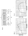
- Fig. 1 shows a normal single-port SAW resonator described in Japanese Patent Application Publication No. 6-338756 (hereinafter referred to as Document 1) and Japanese Patent Application Publication No. 10-215145 (hereinafter referred to as Document 2).
- the SAW resonator includes a pair of comb-like electrodes 10 provided on a piezoelectric substrate.
- the comb-like electrodes 10, which are alternately interleaved on the piezoelectric substrate, are known as interdigital transducer (IDT).
- IDT interdigital transducer
- Each of the comb-like electrodes includes a bus bar and electrode fingers that extend from the bus bar in the same direction.
- a wavelength of the IDT 10 is decided by pitch (period) ⁇ IDT between the electrode fingers that extend from the same bus bar.
- the IDT 10 has a single pitch ⁇ IDT .
- a pair of reflection electrodes 12 and 14 are provided on both sides of the IDT 10.
- the reflection electrodes 12 and 14 shown in Fig. 1 are referred to as a grating-type electrode, and the electrode fingers extending from one bus bar are connected to the other bus bar.
- Pitches ⁇ a and ⁇ b of the reflection electrodes 12 and 14 correspond to the periods between the alternate electrode fingers.
- the reflection electrode 12 has the pitch ⁇ a and the reflection electrode 14 has the pitch ⁇ b.
- ⁇ a is equal to ⁇ b.
- Fig. 2 is a graph illustrating the resonance characteristics of the SAW resonator shown in Fig. 1.
- the horizontal axis denotes frequency (MHz), and the vertical axis denotes attenuation (dB).
- the curve showing the resonance characteristics includes multiple peaks, namely, the ripple component.
- Fig. 3 shows filter characteristics in the case where the filter is composed of the above-mentioned multiple SAW resonators. Referring to Fig. 3, multiple ripple components are included in a passband. In this manner, it is hard to form a flat passband with the conventional filter.
- Present invention has been made in view of the above-mentioned circumstances and provides a SAW device having characteristics in which ripple components are suppressed.
- a surface acoustic wave device comprising a surface acoustic wave resonator.
- the surface acoustic wave resonator includes comb-like electrodes and reflection electrodes provided on both sides of the comb-like electrodes, and each of the reflection electrodes has at least two different pitches.
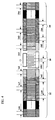
- Fig. 4 shows a SAW device in accordance with an embodiment of the present invention.
- the SAW device includes an IDT 10 and reflection electrodes 22 and 24.
- the IDT 10 is provided on a piezoelectric substrate of piezoelectric single crystal such as LT (LiTaO 3 ) or LN (LiNbO 3 ).
- the piezoelectric substrate corresponds to a paper.
- the reflection electrodes 22 and 24 are arranged on both sides of the IDT 10.
- the SAW device serves as a single-port SAW resonator.
- the IDT 10 comprises a pair of comb-like electrodes, and applies a drive voltage between two bus bars to excite the surface acoustic waves according to the pitch ⁇ IDT .
- the reflection electrodes 22 and 24 provided on the piezoelectric substrate serve as reflectors, and confines the SAW propagated from the IDT 10.
- the inventors of the present invention found that it is possible to decrease ripples in the resonance characteristics of the SAW device, by devising the structure of the reflection electrodes.
- the reflection electrode 22 has n-number different pitches ⁇ a1, ⁇ a2, ⁇ a3, ⁇ a4 ⁇ , and ⁇ an ( ⁇ a1 ⁇ ⁇ a2 ⁇ ⁇ a3 ⁇ ⁇ a4 ⁇ ⁇ ⁇ ⁇ an).
- n is a natural number of two or more.
- the reflection electrode 22 has n-number different wavelengths ⁇ a1, ⁇ a2, ⁇ a3, ⁇ a4 ⁇ , and ⁇ an ( ⁇ a1 ⁇ ⁇ a2 ⁇ ⁇ a3 ⁇ ⁇ a4 ⁇ ⁇ ⁇ an).
- n is a natural number of two or more.
- the reflection electrode 22 includes at least one pair of electrode fingers in each pitch.
- the reflection electrode 22 in Fig. 4 has three pairs of electrode fingers in every pitch. In this manner, the pairs of the electrode fingers in the reflection electrode 22 are divided into n.
- the electrode 22 has pairs of electrode fingers having respectively different pitches ⁇ a1, ⁇ a2, ⁇ a3, ⁇ a4 ⁇ , and ⁇ an.
- the inventors found that the reflection electrode was divided into n having different pitch values and it was possible to reduce the ripple components included in the resonance characteristics. That is to say, the ripples included in the resonance characteristics can be decreased by configuring the reflection electrode 22 to have multiple different reflection wavelengths.
- the reflection electrode 24 has the same configuration as that of the reflection electrode 22. That is, the reflection electrode 24 has n-number different pitches ⁇ b1, ⁇ b2, ⁇ b3, ⁇ b4 ⁇ , and ⁇ bn ( ⁇ b1 ⁇ ⁇ b2 ⁇ ⁇ b3 ⁇ ⁇ b4 ⁇ ⁇ ⁇ ⁇ bn). n is a natural number of two or more. In other words, the reflection electrode 22 has n-number different wavelengths ⁇ b1, ⁇ b2, ⁇ b3, ⁇ b4 ⁇ , and ⁇ bn ( ⁇ b1 ⁇ ⁇ b2 ⁇ ⁇ b3 ⁇ ⁇ b4 ⁇ ⁇ ⁇ ⁇ bn). n is a natural number of two or more.
- the reflection electrode 24 includes at least one pair of electrode fingers in each pitch.
- the reflection electrode 24 in Fig. 4 has three pairs of electrode fingers in every pitch. In this manner, the pairs of the electrode fingers in the reflection electrode 24 are divided into n.
- the electrode 24 has pairs of electrode fingers having respectively different pitches ⁇ b1, ⁇ b2, ⁇ b3, ⁇ b4 ⁇ , and ⁇ bn.
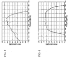
- Fig. 5 shows the resonance characteristics of the SAW device shown in Fig. 4.
- the solid line in Fig. 4 denotes the resonance characteristics of the SAW device.
- the dotted line denotes the resonance characteristics of the conventional SAW device shown in Fig. 2.
- the ripple components of the resonance characteristics can be suppressed.
- Fig. 6 shows the filter characteristics of the SAW device in which the multiple SAW resonators are connected in a ladder structure.
- the bandpass filter characteristics are obtainable.
- the solid line in Fig. 6 denotes the filter characteristics of the SAW resonators shown in Fig. 4.
- the dotted line in Fig. 6 denotes the filter characteristics of the SAW resonators shown in Fig. 1, which are connected in the ladder structure.
- the division number n of the reflection electrodes 22 and 24 is equal.
- corresponding portions of the electrodes 22 and 24 may have the same pitch or may have different pitches.
- part of the multiple pitches of the reflection electrode 22 may be different from those of the reflection electrode 24. The number of pairs of the electrode fingers having the same pitches may be different in the reflection electrodes 22 and 24.
- Fig. 7 shows a SAW device in accordance with a first embodiment of the present invention.
- the SAW device includes the IDT 10 and a pair of reflection electrodes 32 and 34.
- the IDT 10 is provided on a piezoelectric substrate of 42° Y-cut X-propagation LitaO 3 .
- the pair of the reflection electrodes 32 and 34 are arranged on both sides of the IDT 10.
- An electrode pattern arranged on the piezoelectric substrate is made of, for example, a conductive material having aluminum as a main component.
- the reflection electrode 32 is divided into two division parts, a1 and a2.
- One division part a1 includes pairs of the electrode fingers arranged in the pitch of ⁇ a1.
- the other part a2 includes pairs of the electrode fingers arranged in the pitch of ⁇ a2.
- ⁇ a1 is not equal to ⁇ a2. That is, the reflection electrode 32 corresponds to the case where n is equal to 2 in Fig. 4.
- the reflection electrode 34 is divided into two division parts, b1 and b2.
- One division part b1 includes pairs of the electrode fingers arranged in the pitch of ⁇ b1.
- the other part b2 includes pairs of the electrode fingers arranged in the pitch of ⁇ b2.
- ⁇ b1 is not equal to ⁇ b2. That is, the reflection electrode 34 corresponds to the case where n is equal to 2 in Fig. 4.
- the pitch (wavelength) of the reflection electrode 32 and the pitch (wavelength) of the reflection electrode 34 have a relationship that ⁇ a1 is equal to ⁇ b1 and ⁇ a2 is equal to ⁇ b2. Additionally, a reflected wave reflected by the division part a1 is configured to have a reverse phase of that reflected by the division part a2. In the same manner, the reflected wave reflected by the division part b1 is configured to have the reverse phase of that reflected by the division part b2.
- Table 1 shows an example of the pitches ⁇ a1, ⁇ a2, ⁇ b1, and ⁇ b2.
- Table 1 shows an example of the pitches ⁇ a1, ⁇ a2, ⁇ b1, and ⁇ b2.
- the conventional technique has the reflection electrodes of a single pitch in the resonator.
- ⁇ a2 [ ⁇ m] ⁇ a1 [ ⁇ m] ⁇ b1 [ ⁇ m] ⁇ b2 [ ⁇ m]
- Fig. 8 is a graph describing the resonance characteristics in accordance with the first embodiment of the present invention.
- the solid line denotes the resonance characteristics of the first embodiment of the present invention
- the dotted line denotes the resonance characteristics of the comparative example.
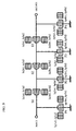
- Fig. 9 is a SAW device in accordance with a second embodiment of the present invention.
- the SAW device is the ladder-type filter.
- This filter includes three series-arm resonators S1, S2, and S3 and four parallel-arm resonators P1, P2, P3, and P4.
- the above-mentioned resonators are connected in the ladder structure.
- the resonators S1 through S3 and P1 through P4 respectively include the SAW resonators shown in Fig. 7.
- the following relationships are established between the series-arm resonators S1 through S3, in the case where the pitches (wavelengths) of the reflection electrodes of the resonators S1 through S3 and P1 through P4 are defined as shown in Fig. 9.
- i is 1 through 3.
- the reflected waves of ⁇ sia1 and ⁇ sia2 are configured to have the reversed phase and the reflected waves of ⁇ pia1 and ⁇ pia2 are configured to have the reversed phase.
- Table 2 shows an example of wavelengths of the resonators.
- a comparative example of the conventional technique is also shown.
- the conventional technique includes the resonators S1 through S3 and P1 through P4 have the reflection electrodes of a single pitch.
- "si" and "pi" are omitted.
- Fig. 10 is a graph showing the filter characteristics of the second embodiment of the present invention.
- the solid line denotes the filter characteristics of the second embodiment of the present invention, and the dotted line denotes the filter characteristics of the comparative example. It is thus possible to reduce the ripples drastically, by configuring the reflection electrodes of the SAW resonators as mentioned above.
- Fig. 11 shows a SAW device in accordance with a third embodiment of the present invention.
- the SAW device is the ladder-type filter and a variation of the second embodiment of the present invention.
- the ladder-type filter shown in fig. 11 includes three series-arm resonators and four parallel-arm resonators.
- the three series-arm resonators are composed of SAW resonators S shown in Fig. 4, which have the same specification.
- the four parallel-arm resonators are composed of SAW resonators P shown in Fig. 1. That is, only the series-arm resonators have the reflection electrodes, each of which has at least two different pitches. In this configuration, it is possible to reduce the ripples drastically as in the filter characteristics defined by the solid line in Fig. 10.
- the ripples in the filter characteristics are mainly caused by the series-arm resonators.
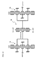
- Fig. 12 is a SAW device in accordance with a fourth embodiment of the present invention.
- the SAW device includes two DMS (Double Mode SAW) filters 52 and 54 and a single-port SAW resonator 56.
- the single-port SAW resonator 56 connects the DMS filters 52 and 54.
- the above-mentioned SAW resonators are arranged on the piezoelectric substrate as in the above-mentioned embodiments of the present invention.
- the DMS filters 52 and 54 respectively include three SAW resonators arranged in a line and a pair of reflection electrodes arranged on both sides of the DMS filters.
- the DMS filter 52 is arranged on an inputs side, and the DMS filter 54 is arranged on an output side.
- the DMS filters 52 and 54 respectively have bandpass characteristics.
- the single-port SAW resonator 56 is provided together with the DMS filters 52 and 54 so as to obtain desirable filter characteristics.
- the SAW resonator 56 is configured as shown in Fig. 4. That is, each of the reflection electrodes of the SAW resonator 56 has at least two different pitches. With this configuration, it is possible to reduce the ripple components included in the passband.
- Table 3 shows an example of the pitches ⁇ a1, ⁇ a2, ⁇ b1, and ⁇ b2 of the SAW resonator 56.
- a comparative example of the conventional technique is also shown.
- the conventional technique includes the resonators, each of which has the reflection electrode of a single pitch.
- ⁇ a2 [ ⁇ m] ⁇ a1 [ ⁇ m] ⁇ b1 [ ⁇ m] ⁇ b2 [ ⁇ m]
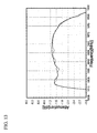
- Fig. 13 is a graph showing the filter characteristics of the fourth embodiment of the present invention.
- the solid line denotes the filter characteristics of the fourth embodiment of the present invention, and the dotted line denotes the filter characteristics of the comparative example. It is thus possible to reduce the ripple drastically, by configuring each reflection electrode of the SAW resonator 56 so that ⁇ a1 is not equal to ⁇ a2 and ⁇ b1 is not equal to ⁇ b2.
Landscapes
- Physics & Mathematics (AREA)
- Acoustics & Sound (AREA)
- Surface Acoustic Wave Elements And Circuit Networks Thereof (AREA)
Applications Claiming Priority (2)
| Application Number | Priority Date | Filing Date | Title |
|---|---|---|---|
| JP2004052502A JP2005244669A (ja) | 2004-02-26 | 2004-02-26 | 弾性表面波装置 |
| JP2004052502 | 2004-02-26 |
Publications (2)
| Publication Number | Publication Date |
|---|---|
| EP1569334A2 true EP1569334A2 (fr) | 2005-08-31 |
| EP1569334A3 EP1569334A3 (fr) | 2008-04-16 |
Family
ID=34747526
Family Applications (1)
| Application Number | Title | Priority Date | Filing Date |
|---|---|---|---|
| EP05250827A Withdrawn EP1569334A3 (fr) | 2004-02-26 | 2005-02-14 | Dispositif à ondes acoustiques de surface |
Country Status (5)
| Country | Link |
|---|---|
| US (1) | US7400220B2 (fr) |
| EP (1) | EP1569334A3 (fr) |
| JP (1) | JP2005244669A (fr) |
| KR (1) | KR100697763B1 (fr) |
| CN (1) | CN1661913A (fr) |
Cited By (1)
| Publication number | Priority date | Publication date | Assignee | Title |
|---|---|---|---|---|
| US20210211117A1 (en) * | 2020-01-06 | 2021-07-08 | Wisol Co., Ltd. | Receiving filter circuit and duplexer having the same |
Families Citing this family (9)
| Publication number | Priority date | Publication date | Assignee | Title |
|---|---|---|---|---|
| DE102012112237A1 (de) * | 2012-12-13 | 2014-06-18 | Epcos Ag | Elektroakustisches Bandpassfilter mit geglätteter Einfügedämpfung |
| JP6247377B2 (ja) | 2014-07-30 | 2017-12-13 | 京セラ株式会社 | 弾性波素子、フィルタ素子および通信装置 |
| DE102014118000A1 (de) * | 2014-12-05 | 2016-06-09 | Epcos Ag | Anordnung mit einem DMS Filter und steiler rechter Flanke |
| CN109845105B (zh) * | 2016-10-13 | 2023-06-13 | 株式会社村田制作所 | 弹性波滤波器装置 |
| JP6886331B2 (ja) | 2017-04-07 | 2021-06-16 | 太陽誘電株式会社 | 弾性波共振器、フィルタおよびマルチプレクサ |
| KR102377662B1 (ko) * | 2017-09-29 | 2022-03-23 | 가부시키가이샤 무라타 세이사쿠쇼 | 멀티플렉서, 고주파 프론트 엔드 회로 및 통신 장치 |
| JP7237556B2 (ja) * | 2018-12-13 | 2023-03-13 | 太陽誘電株式会社 | 弾性波共振器、フィルタおよびマルチプレクサ |
| US11431319B2 (en) | 2019-08-22 | 2022-08-30 | Skyworks Solutions, Inc. | Acoustic wave device with varying electrode pitch |
| US11881836B2 (en) * | 2019-11-25 | 2024-01-23 | Skyworks Solutions, Inc. | Cascaded resonator with different reflector pitch |
Citations (4)
| Publication number | Priority date | Publication date | Assignee | Title |
|---|---|---|---|---|
| EP1267489A2 (fr) * | 2001-06-12 | 2002-12-18 | Murata Manufacturing Co., Ltd. | Filtre à ondes acoustiques de surface |
| EP1320192A1 (fr) * | 2000-07-21 | 2003-06-18 | Kabushiki Kaisha Toshiba | Dispositif de filtrage d'ondes acoustiques de surface |
| US20030169129A1 (en) * | 2002-01-28 | 2003-09-11 | Yuichi Takamine | Surface acoustic wave device and communication apparatus |
| US20030231083A1 (en) * | 2002-02-15 | 2003-12-18 | Andreas Detlefsen | Resonator filter with improved adjacent channel selectivity |
Family Cites Families (7)
| Publication number | Priority date | Publication date | Assignee | Title |
|---|---|---|---|---|
| JPS62199111A (ja) * | 1986-02-27 | 1987-09-02 | Toyo Commun Equip Co Ltd | Idt励振横結合二重モ−ドフイルタ |
| JPH06338756A (ja) | 1993-05-27 | 1994-12-06 | Fujitsu Ltd | 共振子型弾性表面波フィルタ |
| JP3224202B2 (ja) * | 1996-11-28 | 2001-10-29 | 富士通株式会社 | 弾性表面波装置 |
| JP3235498B2 (ja) | 1997-01-30 | 2001-12-04 | 富士通株式会社 | 弾性表面波共振器及びラダー型弾性表面波フィルタ |
| JP4534307B2 (ja) * | 2000-05-24 | 2010-09-01 | パナソニック株式会社 | 弾性表面波フィルタ |
| JP2003188674A (ja) * | 2001-12-19 | 2003-07-04 | Murata Mfg Co Ltd | 弾性表面波装置、通信装置 |
| JP4273935B2 (ja) * | 2003-01-24 | 2009-06-03 | 株式会社村田製作所 | 弾性表面波装置、通信装置 |
-
2004
- 2004-02-26 JP JP2004052502A patent/JP2005244669A/ja not_active Withdrawn
-
2005
- 2005-02-14 EP EP05250827A patent/EP1569334A3/fr not_active Withdrawn
- 2005-02-24 KR KR1020050015384A patent/KR100697763B1/ko not_active IP Right Cessation
- 2005-02-25 US US11/065,363 patent/US7400220B2/en not_active Expired - Fee Related
- 2005-02-28 CN CN2005100524807A patent/CN1661913A/zh active Pending
Patent Citations (4)
| Publication number | Priority date | Publication date | Assignee | Title |
|---|---|---|---|---|
| EP1320192A1 (fr) * | 2000-07-21 | 2003-06-18 | Kabushiki Kaisha Toshiba | Dispositif de filtrage d'ondes acoustiques de surface |
| EP1267489A2 (fr) * | 2001-06-12 | 2002-12-18 | Murata Manufacturing Co., Ltd. | Filtre à ondes acoustiques de surface |
| US20030169129A1 (en) * | 2002-01-28 | 2003-09-11 | Yuichi Takamine | Surface acoustic wave device and communication apparatus |
| US20030231083A1 (en) * | 2002-02-15 | 2003-12-18 | Andreas Detlefsen | Resonator filter with improved adjacent channel selectivity |
Cited By (1)
| Publication number | Priority date | Publication date | Assignee | Title |
|---|---|---|---|---|
| US20210211117A1 (en) * | 2020-01-06 | 2021-07-08 | Wisol Co., Ltd. | Receiving filter circuit and duplexer having the same |
Also Published As
| Publication number | Publication date |
|---|---|
| US20050190014A1 (en) | 2005-09-01 |
| EP1569334A3 (fr) | 2008-04-16 |
| US7400220B2 (en) | 2008-07-15 |
| KR20060042147A (ko) | 2006-05-12 |
| CN1661913A (zh) | 2005-08-31 |
| JP2005244669A (ja) | 2005-09-08 |
| KR100697763B1 (ko) | 2007-03-22 |
Similar Documents
| Publication | Publication Date | Title |
|---|---|---|
| US7400220B2 (en) | Surface acoustic wave device | |
| US6522219B2 (en) | Surface acoustic wave ladder filter with two series resonators having different apodization weighting | |
| KR101793055B1 (ko) | 래더형 필터 | |
| EP1049254A2 (fr) | Résonateur à ondes acoustiques de surface, filtre composite à ondes acoustiques de surface et filtre à ondes acoustiques de surface | |
| US20090091404A1 (en) | Acoustic wave filter device and duplexer | |
| KR100340286B1 (ko) | 탄성 표면파 필터 | |
| CN110114973B (zh) | 弹性波装置 | |
| US6781485B2 (en) | Surface acoustic wave filter | |
| US7042313B2 (en) | Surface acoustic wave device and communication device using the same | |
| US20020153969A1 (en) | Surface acoustic wave resonator and surface acoustic wave filter | |
| KR100379601B1 (ko) | 통과대역의 편평도를 향상시키는 탄성 표면파 필터 및이의 제조 방법 | |
| US7746199B2 (en) | Acoustic wave device | |
| JP2005295203A (ja) | デュプレクサ | |
| JPWO2005013481A1 (ja) | 弾性表面波フィルタ | |
| EP2256925B1 (fr) | Dispositif d'onde élastique | |
| WO2023063254A1 (fr) | Filtre à ondes élastiques et multiplexeur | |
| EP1786100A1 (fr) | Filtre ondulé à surface élastique de type équilibré | |
| JP2004140738A (ja) | 弾性表面波フィルタ | |
| JP3915322B2 (ja) | 弾性表面波フィルタ | |
| JPH11340774A (ja) | 弾性表面波フィルタ | |
| JP4053038B2 (ja) | 弾性表面波装置 | |
| JPH10261935A (ja) | 弾性表面波素子 | |
| US20200313651A1 (en) | Multiplexer | |
| JP2003347896A (ja) | 弾性表面波フィルタ | |
| JPH10261932A (ja) | 弾性表面波フィルタ及び弾性表面波フィルタの構成方法 |
Legal Events
| Date | Code | Title | Description |
|---|---|---|---|
| PUAI | Public reference made under article 153(3) epc to a published international application that has entered the european phase |
Free format text: ORIGINAL CODE: 0009012 |
|
| AK | Designated contracting states |
Kind code of ref document: A2 Designated state(s): AT BE BG CH CY CZ DE DK EE ES FI FR GB GR HU IE IS IT LI LT LU MC NL PL PT RO SE SI SK TR |
|
| AX | Request for extension of the european patent |
Extension state: AL BA HR LV MK YU |
|
| PUAL | Search report despatched |
Free format text: ORIGINAL CODE: 0009013 |
|
| AK | Designated contracting states |
Kind code of ref document: A3 Designated state(s): AT BE BG CH CY CZ DE DK EE ES FI FR GB GR HU IE IS IT LI LT LU MC NL PL PT RO SE SI SK TR |
|
| AX | Request for extension of the european patent |
Extension state: AL BA HR LV MK YU |
|
| 17P | Request for examination filed |
Effective date: 20081013 |
|
| AKX | Designation fees paid |
Designated state(s): DE FR |
|
| STAA | Information on the status of an ep patent application or granted ep patent |
Free format text: STATUS: THE APPLICATION HAS BEEN WITHDRAWN |
|
| 18W | Application withdrawn |
Effective date: 20081208 |