EP1569181B1 - Système de surveillance de maison - Google Patents
Système de surveillance de maison Download PDFInfo
- Publication number
- EP1569181B1 EP1569181B1 EP20040004230 EP04004230A EP1569181B1 EP 1569181 B1 EP1569181 B1 EP 1569181B1 EP 20040004230 EP20040004230 EP 20040004230 EP 04004230 A EP04004230 A EP 04004230A EP 1569181 B1 EP1569181 B1 EP 1569181B1
- Authority
- EP
- European Patent Office
- Prior art keywords
- condition
- display device
- refrigerator
- house
- monitoring
- Prior art date
- Legal status (The legal status is an assumption and is not a legal conclusion. Google has not performed a legal analysis and makes no representation as to the accuracy of the status listed.)
- Expired - Fee Related
Links
Images
Classifications
-
- F—MECHANICAL ENGINEERING; LIGHTING; HEATING; WEAPONS; BLASTING
- F25—REFRIGERATION OR COOLING; COMBINED HEATING AND REFRIGERATION SYSTEMS; HEAT PUMP SYSTEMS; MANUFACTURE OR STORAGE OF ICE; LIQUEFACTION SOLIDIFICATION OF GASES
- F25D—REFRIGERATORS; COLD ROOMS; ICE-BOXES; COOLING OR FREEZING APPARATUS NOT OTHERWISE PROVIDED FOR
- F25D29/00—Arrangement or mounting of control or safety devices
- F25D29/008—Alarm devices
-
- G—PHYSICS
- G08—SIGNALLING
- G08B—SIGNALLING OR CALLING SYSTEMS; ORDER TELEGRAPHS; ALARM SYSTEMS
- G08B19/00—Alarms responsive to two or more different undesired or abnormal conditions, e.g. burglary and fire, abnormal temperature and abnormal rate of flow
-
- G—PHYSICS
- G08—SIGNALLING
- G08B—SIGNALLING OR CALLING SYSTEMS; ORDER TELEGRAPHS; ALARM SYSTEMS
- G08B21/00—Alarms responsive to a single specified undesired or abnormal condition and not otherwise provided for
- G08B21/18—Status alarms
- G08B21/187—Machine fault alarms
-
- F—MECHANICAL ENGINEERING; LIGHTING; HEATING; WEAPONS; BLASTING
- F25—REFRIGERATION OR COOLING; COMBINED HEATING AND REFRIGERATION SYSTEMS; HEAT PUMP SYSTEMS; MANUFACTURE OR STORAGE OF ICE; LIQUEFACTION SOLIDIFICATION OF GASES
- F25B—REFRIGERATION MACHINES, PLANTS OR SYSTEMS; COMBINED HEATING AND REFRIGERATION SYSTEMS; HEAT PUMP SYSTEMS
- F25B2600/00—Control issues
- F25B2600/07—Remote controls
-
- F—MECHANICAL ENGINEERING; LIGHTING; HEATING; WEAPONS; BLASTING
- F25—REFRIGERATION OR COOLING; COMBINED HEATING AND REFRIGERATION SYSTEMS; HEAT PUMP SYSTEMS; MANUFACTURE OR STORAGE OF ICE; LIQUEFACTION SOLIDIFICATION OF GASES
- F25D—REFRIGERATORS; COLD ROOMS; ICE-BOXES; COOLING OR FREEZING APPARATUS NOT OTHERWISE PROVIDED FOR
- F25D2400/00—General features of, or devices for refrigerators, cold rooms, ice-boxes, or for cooling or freezing apparatus not covered by any other subclass
- F25D2400/36—Visual displays
-
- F—MECHANICAL ENGINEERING; LIGHTING; HEATING; WEAPONS; BLASTING
- F25—REFRIGERATION OR COOLING; COMBINED HEATING AND REFRIGERATION SYSTEMS; HEAT PUMP SYSTEMS; MANUFACTURE OR STORAGE OF ICE; LIQUEFACTION SOLIDIFICATION OF GASES
- F25D—REFRIGERATORS; COLD ROOMS; ICE-BOXES; COOLING OR FREEZING APPARATUS NOT OTHERWISE PROVIDED FOR
- F25D2700/00—Means for sensing or measuring; Sensors therefor
- F25D2700/12—Sensors measuring the inside temperature
- F25D2700/122—Sensors measuring the inside temperature of freezer compartments
Definitions
- the invention relates to a system for home surveillance.
- the object of the invention is to provide a system for monitoring the home, which provides users with convenient and secure information about different states in or around the house.
- Document US 5 262 758 describes an alarm unit for a refrigeration system.
- a system for monitoring the house for this purpose with a refrigerator, one or more sensors which monitor a state far away from the refrigerator and generate a signal corresponding to the state, and devices for transmitting the signals to a computer which controls at least one display device on the refrigerator ,
- the invention makes use of the knowledge that the refrigerator is a regularly frequented by residents of a house facility. Thus, if a resident uses the refrigerator, then according to the invention he will be provided with "automatic" status messages about various conditions that are monitored in or at the house according to the invention.
- the invention may be provided on the front of the refrigerator, one or a plurality of display devices preferably, which detects the user when looking at the refrigerator as a matter of course. If the evaluation of sensor signals according to the invention, which is described below, indicates that a condition in or at the home is or could be critical, the user reliably learns "casually" about this hazard without having to go to a specific location to monitor the house.
- the invention does not exclude that said display device also displays information (additional) that affect the refrigerator itself, ie for Example of its temperature, especially if necessary in a freezer compartment of the refrigerator.
- the display device has a plurality of LEDs, in particular LEDs of different colors.
- the user can be given the desired information in an easily recognizable and urgent manner with respect to several states to be monitored in or at home.
- the state to be monitored is the temperature of a freezer (for example in the cellar) remote from the said refrigerator, then a "traffic light" with, for example, three colors green, yellow and red can be provided for this state, the one described below Calculator then, when the temperature in the freezer corresponds to the intended value, with the LED activates the green light, while when the temperature is close to an undesirable limit, with the LED the color is yellow, and then when the temperature in the freezer is above a predetermined limit, with the LED the color is displayed in red.
- a "traffic light" with, for example, three colors green, yellow and red
- condition monitoring can be used: temperature of an external water pipe, moisture in a place in the kitchen of the house, moisture in a place in the basement of the house, condition of a filter, condition of a lifting plant, condition of heating, Condition of a garage door, condition of a monitoring device, eg Motion detector or security system.
- a display device with a text display can be provided, with which the user is provided with more precise information about states to be monitored, for example digital numerical values with respect to measured temperatures, messages on the extent to which the measured numerical values are critical, messages about time periods within which For example, maintenance at other facilities in the home are to be made, or indications of periods, which remain until such maintenance is carried out at the latest, etc.
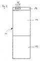
- Figure 1 shows a refrigerator 10 having, for example, two doors 12, 14, which allow access to different cold rooms.
- a display device 18 with individual LEDs is arranged in a header 16 above the upper door 14, a display device 18 with individual LEDs (light emitting diodes) is arranged.
- the letters a, b, c and d can each designate different LEDs with different colors, for example green, yellow, orange and red. These colors can be assigned in a noticeable manner to different states of a parameter to be monitored, for example the temperature in a freezer. In a simple case, three LEDs would be sufficient to inform a visitor with sufficient accuracy of the respective current states of the parameter to be monitored.
- Figure 1 can also be assigned so that the light panels 18a, 18b, 18c and 18d respectively different states that are monitored in the house, are assigned, so for example, the light field a of the temperature in the freezer, the Light field b of a moisture at a location in the basement of the house (water damage), the illuminated field c the state of a heater (for example, an electronically detected with modern heating systems operating state), and the light field d a fourth parameter, such as the opening state of a garage door ( open or closed).
- each of the four luminous fields a, b, c and d can then be illuminated in different colors (for example green, yellow and red).
- LEDs are available which can be controlled differently by an electronic system and, for example, mix different final colors together from three color components, that is, for example, the desired end colors green, yellow or red.
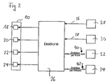
- Figure 2 shows an arrangement of sensors, a computer and display devices that correspond to the latter embodiment.
- devices 28, 30, 32 and 34 to be designated as sensors are provided in the broader sense, which may each have different configurations.
- the sensor 28 may monitor a garage door, so determine whether the door is reliably closed or not.
- the sensor 28 then sends a corresponding signal via a line 36 to a computer 26 (which can also be designed as hardwired electronics), which processes this signal and correspondingly activates a display device, for example 18.
- the display device 18 is provided with LEDs so that the computer 26 performs a circuit of the LEDs to the effect that with the garage door closed, the display device 18 associated field lights (for example, the field a in Figure 1) green, while if the Garage door is not closed, the light field a lights up red, in accordance with other loading of the LED assigned to this field.
- the display device 18 associated field lights (for example, the field a in Figure 1) green, while if the Garage door is not closed, the light field a lights up red, in accordance with other loading of the LED assigned to this field.
- the sensor 30 may be, for example, a signaling device which signals water at an undesirable location, for example in the kitchen behind cabinets or in the basement, for example near a washing machine or the like.
- the sensor 30 then reports a corresponding signal via the line 38 to the computer 26, which carries out the evaluation, to then control another display device 20 in the form of another light field, so for example the light field b in Figure 1, analogous to the garage door described above ,
- Measuring instruments with which the moisture itself can be measured are available to the person skilled in the art from other sources. The same applies to the above-described state of the garage door, which can be determined, for example, electrically by a simple switch, which is closed in the closed state.
- the sensor 32 may be, for example, a device with which a heater is monitored, for example, the determination of whether the heater is ready for operation, there is a fault, or is turned off.
- Such heating monitors are known as such to the person skilled in the art. They can provide a desired signal on the heating state, which is then communicated wirelessly in the embodiment of Figure 2 via the radio link 40 to the computer 26, which has a corresponding receiver for this purpose.
- the evaluation is carried out analogously to the one described above, that is to say such that the display device 22 assigned to the heating state corresponds, for example, to the field c in FIG. 1, a red signal indicating that a fault condition exists in the heating system.
- the further sensor 34 may also be, for example, a monitoring device which measures the temperature in a garden water line (outside the house) in order to indicate a possible risk of freezing.
- the transmission of the signal to the computer 26 takes place wirelessly via the infrared link 42, for which then the computer 26 is equipped with a corresponding receiver.
- the computer 26 or the corresponding electronics is preferably arranged in the control part of the refrigerator 10.
- the sensors may optionally be connected via wire lines 36, 38, wireless links 40 or wireless infrared links, as needed and designed.
Landscapes
- Engineering & Computer Science (AREA)
- Physics & Mathematics (AREA)
- General Physics & Mathematics (AREA)
- Chemical & Material Sciences (AREA)
- Combustion & Propulsion (AREA)
- Mechanical Engineering (AREA)
- Thermal Sciences (AREA)
- General Engineering & Computer Science (AREA)
- Business, Economics & Management (AREA)
- Emergency Management (AREA)
- Cold Air Circulating Systems And Constructional Details In Refrigerators (AREA)
- Devices That Are Associated With Refrigeration Equipment (AREA)
Claims (5)
- Système pour la surveillance domestique présentant un réfrigérateur (10), un ou plusieurs capteurs (28, 30, 32, 34) qui surveillent chacun un état à distance du réfrigérateur (10) et qui produisent un signal correspondant à l'état, et des dispositifs (36, 38, 40, 42) pour transmettre les signaux à un calculateur (26) qui commande pour le moins un dispositif d'affichage (18, 20, 22, 24) situé sur le réfrigérateur (10).
- Système selon la revendication 1, caractérisé en ce que le dispositif d'affichage (18, 20, 22, 24) présente plusieurs DEL, notamment des DEL de couleur différente.
- Système selon l'une des revendications 1 ou 2, caractérisé en ce que le dispositif d'affichage présente un affichage sous forme de texte.
- Système selon l'une des revendications précédentes, caractérisé en ce que les capteurs (28, 30, 32, 34) surveillent un ou plusieurs des états suivants :- température d'un congélateur,- température d'une conduite d'eau extérieure,- humidité en un point de la cuisine, à l'intérieur de la maison,- humidité en un point de la cave, à l'intérieur de la maison,- état d'un filtre,- état d'une installation de levage,- état d'un chauffage,- état d'une porte de garage,- état d'un dispositif de surveillance, tel qu'un détecteur de mouvement ou une installation de sécurité.
- Système selon l'une des revendications précédentes, caractérisé en ce que le dispositif d'affichage affiche des intervalles de maintenance réguliers.
Priority Applications (2)
| Application Number | Priority Date | Filing Date | Title |
|---|---|---|---|
| DE200450002951 DE502004002951D1 (de) | 2004-02-25 | 2004-02-25 | System zur Hausüberwachung |
| EP20040004230 EP1569181B1 (fr) | 2004-02-25 | 2004-02-25 | Système de surveillance de maison |
Applications Claiming Priority (1)
| Application Number | Priority Date | Filing Date | Title |
|---|---|---|---|
| EP20040004230 EP1569181B1 (fr) | 2004-02-25 | 2004-02-25 | Système de surveillance de maison |
Publications (2)
| Publication Number | Publication Date |
|---|---|
| EP1569181A1 EP1569181A1 (fr) | 2005-08-31 |
| EP1569181B1 true EP1569181B1 (fr) | 2007-02-21 |
Family
ID=34745885
Family Applications (1)
| Application Number | Title | Priority Date | Filing Date |
|---|---|---|---|
| EP20040004230 Expired - Fee Related EP1569181B1 (fr) | 2004-02-25 | 2004-02-25 | Système de surveillance de maison |
Country Status (2)
| Country | Link |
|---|---|
| EP (1) | EP1569181B1 (fr) |
| DE (1) | DE502004002951D1 (fr) |
Families Citing this family (1)
| Publication number | Priority date | Publication date | Assignee | Title |
|---|---|---|---|---|
| GB2488067B (en) * | 2009-11-13 | 2016-09-28 | Leica Instr (Singapore) Pte Ltd | Display of a system state of a treatment device for microscopic samples |
Family Cites Families (2)
| Publication number | Priority date | Publication date | Assignee | Title |
|---|---|---|---|---|
| US4612537A (en) * | 1985-01-28 | 1986-09-16 | Maritonex Inc. | Alarm system for monitoring the temperature of a liquid contained in a reservoir |
| US5262758A (en) * | 1991-09-19 | 1993-11-16 | Nam Young K | System and method for monitoring temperature |
-
2004
- 2004-02-25 EP EP20040004230 patent/EP1569181B1/fr not_active Expired - Fee Related
- 2004-02-25 DE DE200450002951 patent/DE502004002951D1/de not_active Expired - Fee Related
Also Published As
| Publication number | Publication date |
|---|---|
| DE502004002951D1 (de) | 2007-04-05 |
| EP1569181A1 (fr) | 2005-08-31 |
Similar Documents
| Publication | Publication Date | Title |
|---|---|---|
| DE102005025541A1 (de) | Steckdose und Anzeigesystem eines Gebäudes mit mehreren Steckdosen | |
| DE19609689B4 (de) | Schaltschrank mit einer zentralen Steuerungseinrichtung zum Überwachen, Steuern und/oder Regeln von Einbau- und/oder Anbaueinheiten | |
| DE102004025889A1 (de) | Statuszustands-Übertragungsvorrichtung und Verfahren für Betätigungseinheit für bewegliche Schranke | |
| DE102004013601A1 (de) | Bewegliches Barrierenbetriebsverfahren und Vorrichtung | |
| DE60116965T2 (de) | Verbindbarer Detector mit lokaler Alarmanzeige | |
| EP1393142B1 (fr) | Systeme de surveillance d'armoire de commande | |
| DE102011055222A1 (de) | Schalt- und Anzeigevorrichtung | |
| EP3018428A2 (fr) | Champ de commande pour un appareil de chauffage | |
| EP1569181B1 (fr) | Système de surveillance de maison | |
| DE102014105877A1 (de) | Steckdosenempfänger | |
| EP2250716B1 (fr) | Dispositif de surveillance d'armoires de contrôle | |
| DE10064165A1 (de) | Verfahren und Vorrichtung zur Steuerung und Überwachung des Energieverbrauchs | |
| EP2934242B1 (fr) | Procédé de surveillance d'un appareil de cuisson et appareil de cuisson pourvu d'un capteur de température | |
| DE19505677A1 (de) | Steuerungssystem zur Ansteuerung von Einrichtungen im Haushaltsbereich | |
| DE10118120C1 (de) | Beleuchtungssystem für Handhaben | |
| DE102005044684B3 (de) | Einrichtung zur Versorgung von Leuchtelementen mit elektrischer Energie | |
| DE102015013466B4 (de) | Bediengerät | |
| DE102005025539B3 (de) | Anzeigesystem eines Gebäudes | |
| EP0727861B1 (fr) | Système de commande pour appareils à usage domestique | |
| DE10161576A1 (de) | Steuerungsvorrichtung für ein Kühlgerät | |
| DE19724063C2 (de) | Sicherheits-Schalteinrichtung | |
| CN203275972U (zh) | 阀室监控系统 | |
| DE19944843B4 (de) | Alarmsystem | |
| DE102014203883B4 (de) | Verfahren zum Abschalten eines Elektrokochgeräts und Elektrokochgerät | |
| DE10326432A1 (de) | Fluchtrichtungsanzeigesystem, Anzeigevorrichtung zur Verwendung darin sowie Verfahren zur Ansteuerung einer Anzeigevorrichtung |
Legal Events
| Date | Code | Title | Description |
|---|---|---|---|
| PUAI | Public reference made under article 153(3) epc to a published international application that has entered the european phase |
Free format text: ORIGINAL CODE: 0009012 |
|
| AK | Designated contracting states |
Kind code of ref document: A1 Designated state(s): AT BE BG CH CY CZ DE DK EE ES FI FR GB GR HU IE IT LI LU MC NL PT RO SE SI SK TR |
|
| AX | Request for extension of the european patent |
Extension state: AL LT LV MK |
|
| RAP1 | Party data changed (applicant data changed or rights of an application transferred) |
Owner name: EMZ-HANAUER GMBH & CO. KGAA. |
|
| GRAP | Despatch of communication of intention to grant a patent |
Free format text: ORIGINAL CODE: EPIDOSNIGR1 |
|
| 17P | Request for examination filed |
Effective date: 20051219 |
|
| GRAS | Grant fee paid |
Free format text: ORIGINAL CODE: EPIDOSNIGR3 |
|
| AKX | Designation fees paid |
Designated state(s): DE |
|
| GRAA | (expected) grant |
Free format text: ORIGINAL CODE: 0009210 |
|
| AK | Designated contracting states |
Kind code of ref document: B1 Designated state(s): DE |
|
| REF | Corresponds to: |
Ref document number: 502004002951 Country of ref document: DE Date of ref document: 20070405 Kind code of ref document: P |
|
| PLBE | No opposition filed within time limit |
Free format text: ORIGINAL CODE: 0009261 |
|
| STAA | Information on the status of an ep patent application or granted ep patent |
Free format text: STATUS: NO OPPOSITION FILED WITHIN TIME LIMIT |
|
| 26N | No opposition filed |
Effective date: 20071122 |
|
| PGFP | Annual fee paid to national office [announced via postgrant information from national office to epo] |
Ref country code: DE Payment date: 20080225 Year of fee payment: 5 |
|
| PG25 | Lapsed in a contracting state [announced via postgrant information from national office to epo] |
Ref country code: DE Free format text: LAPSE BECAUSE OF NON-PAYMENT OF DUE FEES Effective date: 20090901 |