EP1568930B1 - Schelle - Google Patents
Schelle Download PDFInfo
- Publication number
- EP1568930B1 EP1568930B1 EP05000957A EP05000957A EP1568930B1 EP 1568930 B1 EP1568930 B1 EP 1568930B1 EP 05000957 A EP05000957 A EP 05000957A EP 05000957 A EP05000957 A EP 05000957A EP 1568930 B1 EP1568930 B1 EP 1568930B1
- Authority
- EP
- European Patent Office
- Prior art keywords
- joint part
- joint
- double
- hole
- holes
- Prior art date
- Legal status (The legal status is an assumption and is not a legal conclusion. Google has not performed a legal analysis and makes no representation as to the accuracy of the status listed.)
- Expired - Lifetime
Links
Images



Classifications
-
- F—MECHANICAL ENGINEERING; LIGHTING; HEATING; WEAPONS; BLASTING
- F16—ENGINEERING ELEMENTS AND UNITS; GENERAL MEASURES FOR PRODUCING AND MAINTAINING EFFECTIVE FUNCTIONING OF MACHINES OR INSTALLATIONS; THERMAL INSULATION IN GENERAL
- F16L—PIPES; JOINTS OR FITTINGS FOR PIPES; SUPPORTS FOR PIPES, CABLES OR PROTECTIVE TUBING; MEANS FOR THERMAL INSULATION IN GENERAL
- F16L21/00—Joints with sleeve or socket
- F16L21/08—Joints with sleeve or socket with additional locking means
-
- F—MECHANICAL ENGINEERING; LIGHTING; HEATING; WEAPONS; BLASTING
- F16—ENGINEERING ELEMENTS AND UNITS; GENERAL MEASURES FOR PRODUCING AND MAINTAINING EFFECTIVE FUNCTIONING OF MACHINES OR INSTALLATIONS; THERMAL INSULATION IN GENERAL
- F16B—DEVICES FOR FASTENING OR SECURING CONSTRUCTIONAL ELEMENTS OR MACHINE PARTS TOGETHER, e.g. NAILS, BOLTS, CIRCLIPS, CLAMPS, CLIPS OR WEDGES; JOINTS OR JOINTING
- F16B37/00—Nuts or like thread-engaging members
- F16B37/04—Devices for fastening nuts to surfaces, e.g. sheets, plates
- F16B37/045—Devices for fastening nuts to surfaces, e.g. sheets, plates specially adapted for fastening in channels, e.g. sliding bolts, channel nuts
- F16B37/047—Barrel nuts
-
- F—MECHANICAL ENGINEERING; LIGHTING; HEATING; WEAPONS; BLASTING
- F16—ENGINEERING ELEMENTS AND UNITS; GENERAL MEASURES FOR PRODUCING AND MAINTAINING EFFECTIVE FUNCTIONING OF MACHINES OR INSTALLATIONS; THERMAL INSULATION IN GENERAL
- F16L—PIPES; JOINTS OR FITTINGS FOR PIPES; SUPPORTS FOR PIPES, CABLES OR PROTECTIVE TUBING; MEANS FOR THERMAL INSULATION IN GENERAL
- F16L21/00—Joints with sleeve or socket
- F16L21/002—Sleeves or nipples for pipes of the same diameter; Reduction pieces
- F16L21/005—Sleeves or nipples for pipes of the same diameter; Reduction pieces made of elastic material, e.g. partly or completely surrounded by clamping devices
-
- F—MECHANICAL ENGINEERING; LIGHTING; HEATING; WEAPONS; BLASTING
- F16—ENGINEERING ELEMENTS AND UNITS; GENERAL MEASURES FOR PRODUCING AND MAINTAINING EFFECTIVE FUNCTIONING OF MACHINES OR INSTALLATIONS; THERMAL INSULATION IN GENERAL
- F16L—PIPES; JOINTS OR FITTINGS FOR PIPES; SUPPORTS FOR PIPES, CABLES OR PROTECTIVE TUBING; MEANS FOR THERMAL INSULATION IN GENERAL
- F16L33/00—Arrangements for connecting hoses to rigid members; Rigid hose-connectors, i.e. single members engaging both hoses
- F16L33/02—Hose-clips
- F16L33/04—Hose-clips tightened by tangentially-arranged threaded pin and nut
Definitions
- the invention relates to a clamp with a clamp band, which has closed loops at its ends, each partially surrounding a largely cylindrical hinge part, and with at least one through slots in the loops and through a thread-free hole in the one hinge part guided clamping screw with their Head during clamping on the one hinge part rotatably rests and engages in a threaded hole in the other hinge part.
- the clamp can be used as a pipe coupling for connecting two pipes, but also serve as a hose clamp.
- the joint parts are designed as massive bolts.
- the clamp has two at each end of its clamp band Loops. In each loop, a hinge pin is rotatably mounted. The hinge pins in the loops of each clamp band end are connected by a plate. This design of the closure of the clamp is expensive.
- the joint parts are formed as sleeves (DE 37 29 372 C2).
- the sleeves are provided in their wall with through holes, wherein the clamping screw is supported with its head on the edge of the hole of a sleeve and is provided with a nut which is supported on the edge of a hole in the other sleeve.
- a nut is required in addition, and at high clamping forces there is a risk that the joint sleeves are deformed by the clamping screw head and / or the mother.
- a clamp according to the preamble of claim 1 is known from document DE 19822915.
- the invention has for its object to provide a clamp of the type mentioned, in which fewer items are required and the joint parts continue to withstand high clamping forces.
- this object is achieved in that the joint parts are formed as sleeves and are compressed at the periphery of their diametrically opposed holes radially to its longitudinal central axis to a double hole.
- the hole edges are based on each joint part from each other.
- the hinge parts therefore withstand high clamping forces in the area of their holes without deformation.
- the formation of the joint parts as sleeves is easily by round bending of a Sheets possible. Nevertheless, you can still get along without a mother.
- edges of the or each threaded double hole are coaxially pulled inwardly to the longitudinal center axis of the one hinge part to the mutual contact, so that there is a transverse through the one hinge part extending double hole, which is longer than twice the wall thickness of a joint part is.
- This design has the advantage that the thread in the or each double hole over a greater length can be provided with correspondingly more turns for engagement of the clamping screw, as if the thread would be formed only over a length corresponding to twice the wall thickness in the hole edges of a double hole ,
- the thread is rolled in the or each double hole of a joint part.
- it is possible to cut the respective thread with a tap.
- a second recess is formed diametrically with respect to the longitudinal center axis of the threaded joint part opposite to the first recess.
- the hinge parts can then be introduced into the loops either in one of two angular positions offset by 180 ° from one another.
- the wall thickness is not reduced thereby.
- the projection may be formed by pressing the loop portion on its side facing away from the projection.
- the clamp of Fig. 1 has a clamp band 1 of two connected by a flexible joint 2 halves.
- the end portions of the clamp band 1 are bent to closed loops 4 and 5 and connected to the outside of the clamp band 1 by spot welds 6.
- the loops 4 and 5 each surround a largely cylindrical hinge part 7 and 8 partially.
- Through two slots 9, 10 in each loop 4, 5 as well as through unthreaded holes 11 in the hinge part 8 passed through clamping screws 12 are with its head 13 during clamping on one hinge part 8 rotatably and engage in threaded holes 14 in the other Joint part 7 a.
- the hinge parts 7, 8 are formed as sleeves and compressed at the periphery of their diametrically opposed holes 11 a, 14 a radially to its longitudinal central axis to a double hole 11, 14.
- the joint parts are therefore loadable by higher clamping forces of the clamping screws 12, as if the holes 11a and 14a not together would rest, for example, only in the peripheral wall area of the joint parts 7, 8 would be.
- each threaded double hole 14 is coaxially pulled inwardly to the longitudinal center axis of the joint part 7 through to the mutual contact, so that there is a transversely through the joint part 7 extending double hole 14, which is longer than twice the wall thickness of the joint part 7. This makes it possible to form the thread in the double hole 14 by a lot more threads than holes 14a, which would be formed only in the peripheral wall of the joint part 7.
- the threads in the double holes 14 of the joint part 7 are rolled and not cut, so cold formed.
- the threads therefore withstand higher clamping forces.
- a recess 16 extending in the circumferential direction of the hinge part 7 for engaging a projection 17 on the inside of a loop part 4a of the clamp band 1 partly surrounding the hinge part 7 between the double holes 14 is formed between the double holes 14 , This prevents that the hinge part 7 can fall out of the loop 4, before the clamping screws 12 have been screwed into the holes 14.
- a second recess 18 is formed.
- the lead 17 can then intervene instead of in the recess 16 in the recess 18 when the hinge member 7 has been introduced rotated by 180 ° relative to the position shown in FIGS. 15 and 16 in the loop 4.
- the joint part 7 is therefore largely independent of position in the loop 4 mountable.
- the recesses 16 and 18 are in the wall of the joint part 7 indented notches. As a result, the wall cross-section, unlike an incised notch, hardly weakened. Since the recesses 16, 18 extend in the circumferential direction of the joint part 7, the hinge part 7 can continue, in spite of the engaging in one of the recesses 16 and 18 projection 17 (Fig. 15), in its loop 4, as well as the hinge part 8 in his loop 5, twist when the clamping screws 12 are inserted and tightened in the holes 11 and 14.
- the projection 17 is formed by pressing the loop portion 4 a on its side facing away from the projection 17. Also, this projection does not weaken the wall thickness of the loop portion 4a and is - similar to a bead - relatively stiff.
- joint part 8 can be dispensed with depressions corresponding to the wells 16 and 18, and in the loop portion 5a of the loop 5 on a projection 17 corresponding projection, because the hinge part 8 is secured by the clamping screws 12 against falling out of the loop 5, as soon the screws 12 are inserted into the holes 11, the screws 12 also protruding on their out of the respective hole 11 Threaded section with a (not shown) thin rubber ring can be secured against falling out of the holes 11 itself.
- the invention is also applicable to clamps, which have only one clamping screw and accordingly in the respective joint part only a through hole like the hole 11 or a threaded hole, such as the hole 14, and accordingly with only two Loop parts are provided at each clamp band end.
Landscapes
- Engineering & Computer Science (AREA)
- General Engineering & Computer Science (AREA)
- Mechanical Engineering (AREA)
- Clamps And Clips (AREA)
- Gripping Jigs, Holding Jigs, And Positioning Jigs (AREA)
- Wire Bonding (AREA)
- Installation Of Indoor Wiring (AREA)
Description
- Die Erfindung betrifft eine Schelle mit einem Schellenband, das an seinen Enden geschlossene Schlaufen aufweist, die jeweils ein weitgehend zylindrisches Gelenkteil teilweise umgeben, und mit mindestens einer durch Schlitze in den Schlaufen sowie durch ein gewindefreies Loch in dem einen Gelenkteil hindurchgeführten Spannschraube, die mit ihrem Kopf beim Spannen an dem einen Gelenkteil drehbar anliegt und in ein mit Gewinde versehenes Loch in dem anderen Gelenkteil eingreift.
- Die Schelle kann als Rohrkupplung zum Verbinden zweier Rohre verwendet werden, aber auch als Schlauchschelle dienen.
- Bei einer bekannten Schelle dieser Art (DE 37 10 852 C1) sind die Gelenkteile als massive Bolzen ausgebildet. Die Schelle hat an jedem Ende ihres Schellenbandes zwei Schlaufen. In jeder Schlaufe ist ein Gelenkbolzen drehbar gelagert. Die Gelenkbolzen in den Schlaufen jedes Schellenbandendes sind durch eine Platte verbunden. Diese Ausbildung des Verschlusses der Schelle ist aufwendig.
- Ferner ist es bekannt, die Gelenkteile als Hülsen auszubilden (DE 37 29 372 C2). Die Hülsen sind in ihrer Wand mit durchgehenden Löchern versehen, wobei sich die Spannschraube mit ihrem Kopf am Rand des Loches der einen Hülse abstützt und mit einer Mutter versehen ist, die sich am Rand eines Loches in der anderen Hülse abstützt. Bei dieser Ausbildung ist zusätzlich eine Mutter erforderlich, und bei hohen Spannkräften besteht die Gefahr, daß die Gelenkhülsen durch den Spannschraubenkopf und/oder die Mutter verformt werden.
- Eine Schelle gemäß dem Oberbegriff des Anspruchs 1 ist aus Dokument DE 19822915 bekannt.
- Der Erfindung liegt die Aufgabe zugrunde, eine Schelle der eingangs genannten Art anzugeben, bei der weniger Einzelteile erforderlich sind und die Gelenkteile weiterhin hohen Spannkräften standhalten.
- Erfindungsgemäß ist diese Aufgabe dadurch gelöst, daß die Gelenkteile als Hülsen ausgebildet und am Umfang ihrer sich diametral gegenüberliegenden Löcher radial zu ihrer Längsmittelachse hin zu einem Doppelloch zusammengedrückt sind.
- Bei dieser Ausbildung stützen sich die Lochränder bei jedem Gelenkteil aneinander ab. Die Gelenkteile halten daher im Bereich ihrer Löcher hohen Spannkräften ohne Verformung stand. Die Ausbildung der Gelenkteile als Hülsen ist auf einfache Weise durch Rundbiegen eines Bleches möglich. Dennoch kommt man weiterhin ohne eine Mutter aus.
- Vorzugsweise ist dafür gesorgt, daß die Ränder des oder jedes mit Gewinde versehenen Doppellochs koaxial nach innen zur Längsmittelachse des einen Gelenkteils hin bis zur gegenseitigen Anlage durchgezogen sind, so daß sich ein quer durch das eine Gelenkteil erstreckendes Doppelloch ergibt, das länger als die zweifache Wandstärke des einen Gelenkteils ist. Diese Ausbildung hat den Vorteil, daß das Gewinde in dem oder jedem Doppelloch über eine größere Länge mit entsprechend mehr Windungen für den Eingriff der Spannschraube versehen werden kann, als wenn das Gewinde nur über eine Länge entsprechend der doppelten Wandstärke in den Lochrändern eines Doppellochs ausgebildet wäre.
- Sodann ist es vorteilhaft, wenn das Gewinde in dem oder jedem Doppelloch des einen Gelenkteils gerollt ist. Prinzipiell ist es zwar möglich, das jeweilige Gewinde mit einem Gewindeschneider zu schneiden. Dagegen hat das Rollen den Vorteil, daß das Gewinde nicht geschnitten, sondern kaltgeformt wird. Dadurch erhöht sich die Belastbarkeit des Gewindes.
- Sodann kann dafür gesorgt sein, daß bei Ausbildung der Gelenkteile mit zwei Doppellöchern in dem mit Gewinde versehenen Gelenkteil zwischen den Doppellöchern eine in der Außenseite dieses Gelenkteils sich in Umfangsrichtung des Gelenkteils erstreckende Vertiefung für den Eingriff eines Vorsprungs auf der Innenseite eines dieses Gelenkteil zwischen den Doppellöchern teilweise umgebenden Schlaufenteils des Schellenbands ausgebildet ist. Sobald hierbei Kerbe und Vorsprung beim Zusammenbau der Schelle ineinandergreifen, kann das betreffende Gelenkteil nicht von selbst aus den Schlaufen herausfallen, bevor der Verschluß geschlossen ist.
- Vorzugsweise ist eine zweite Vertiefung diametral in bezug auf die Längsmittelachse des mit Gewinde versehenen Gelenkteils gegenüber der ersten Vertiefung ausgebildet. Die Gelenkteile können dann wahlweise in einer von zwei um 180° zueinander versetzten Drehwinkellagen in die Schlaufen eingeführt werden.
- Wenn die Vertiefungen in die Wand des Gelenkteils, ähnlich wie Sicken, eingedrückte Kerben sind, wird die Wandstärke dadurch nicht verringert.
- Auch der Vorsprung kann durch Eindrücken des Schlaufenteils auf seiner dem Vorsprung abgewandten Seite gebildet sein.
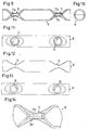
- Die Erfindung und ihre Weiterbildungen werden nachstehend anhand der beigefügten Zeichnung eines bevorzugten Ausführungsbeispiels einer erfindungsgemäßen Schelle näher beschrieben. Darin stellen dar:
- Fig. 1
- eine perspektivische Ansicht des Ausführungsbeispiels einer Schellegemäß dem Stand der Technik
- Fig. 2
- einen Axialschnitt durch ein erstes Gelenkteil einer erfindungsgemäßen Schelle,
- Fig. 3
- eine Seitenansicht des Gelenkteils nach Fig. 2,
- Fig. 4
- eine Axialansicht des Gelenkteils nach Fig. 2,
- Fig. 5
- eine gegenüber Fig. 3 um 90° gedrehte Ansicht des Gelenkteils nach Fig. 2,
- Fig. 6
- eine gegenüber Fig. 5 um 90° gedrehte Ansicht des Gelenkteils nach Fig. 2,
- Fig. 7
- eine gegenüber Fig. 6 um 90° gedrehte Ansicht des Gelenkteils nach Fig. 2,
- Fig. 8
- einen Querschnitt durch die Mitte des Gelenkteils nach Fig. 2,
- Fig. 9
- einen Axialschnitt durch ein zweites Gelenkteil der Schelle nach Fig. 1,
- Fig. 10
- eine Axialansicht des Gelenkteils nach Fig. 9,
- Fig. 11
- eine Draufsicht auf das Gelenkteil nach Fig. 9,.
- Fig. 12
- eine gegenüber Fig. 11 um 90° gedrehte Seitenansicht des Gelenkteils nach Fig. 9,
- Fig. 13
- eine gegenüber Fig. 12 um 90° gedrehte Ansicht des Gelenkteils nach Fig. 9,
- Fig. 14
- einen vergrößerten Ausschnitt der Ansicht nach Fig. 9,
- Fig. 15
- den Schnitt XV-XV durch die eine Schlaufe der Schelle und das darin eingesetzte Gelenkteil und
- Fig. 16
- einen Querschnitt durch die axiale Mitte der einen Schlaufe und das darin eingesetzte Gelenkteil.
- Die Schelle nach Fig. 1 besitzt ein Schellenband 1 aus zwei durch ein biegsames Gelenk 2 verbundenen Hälften. Die Endabschnitte des Schellenbands 1 sind zu geschlossenen Schlaufen 4 und 5 umgebogen und mit der Außenseite des Schellenbands 1 durch Punktschweißungen 6 verbunden. Dabei umgeben die Schlaufen 4 und 5 jeweils ein weitgehend zylindrisches Gelenkteil 7 und 8 teilweise. Durch zwei Schlitze 9, 10 in jeder Schlaufe 4, 5 sowie durch gewindefreie Löcher 11 in dem einen Gelenkteil 8 hindurchgeführte Spannschrauben 12 liegen mit ihrem Kopf 13 beim Spannen an dem einen Gelenkteil 8 drehbar an und greifen in mit Gewinde versehene Löcher 14 in dem anderen Gelenkteil 7 ein.
- Wie die Fig. 2 bis 16 zeigen, sind die Gelenkteile 7, 8 als Hülsen ausgebildet und am Umfang ihrer sich diametral gegenüberliegenden Löcher 11a, 14a radial zu ihrer Längsmittelachse hin zu einem Doppelloch 11, 14 zusammengedrückt. Im Bereich der Löcher beziehungsweise Doppellöcher 11, 14 sind die Gelenkteile daher durch höhere Spannkräfte der Spannschrauben 12 belastbar, als wenn die Löcher 11a beziehungsweise 14a nicht aneinander anliegen würden, zum Beispiel nur im Umfangswandbereich der Gelenkteile 7, 8 lägen.
- Die Ränder 15 jedes mit Gewinde versehenen Doppellochs 14 sind koaxial nach innen zur Längsmittelachse des Gelenkteils 7 hin bis zur gegenseitigen Anlage durchgezogen, so daß sich ein quer durch das Gelenkteil 7 erstreckendes Doppelloch 14 ergibt, das länger als die zweifache Wandstärke des Gelenkteils 7 ist. Dadurch ist es möglich, das Gewinde im Doppelloch 14 durch sehr viel mehr Gewindegänge als bei Löchern 14a auszubilden, die nur in der Umfangswand des Gelenkteils 7 ausgebildet wären.
- Die Gewinde in den Doppellöchern 14 des Gelenkteils 7 sind eingerollt und nicht eingeschnitten, also kaltverformt. Die Gewinde halten daher höheren Spannkräften stand.
- In dem Gelenkteil 7 ist zwischen den Doppellöchern 14 eine in der Außenseite dieses Gelenkteils 7 sich in Umfangsrichtung des Gelenkteils 7 erstreckende Vertiefung 16 für den Eingriff eines Vorsprungs 17 auf der Innenseite eines das Gelenkteil 7 zwischen den Doppellöchern 14 teilweise umgebenden Schlaufenteils 4a des Schellenbands 1 ausgebildet. Dadurch wird verhindert, daß das Gelenkteil 7 aus der Schlaufe 4 herausfallen kann, bevor die Spannschrauben 12 in die Löcher 14 eingeschraubt worden sind.
- Diametral in bezug auf die Mittelachse des mit Gewinde versehenen Gelenkteils 7 gegenüber der Vertiefung 16 ist eine zweite Vertiefung 18 ausgebildet. Der Vorsprung 17 kann dann statt in die Vertiefung 16 auch in die Vertiefung 18 eingreifen, wenn das Gelenkteil 7 um 180° gegenüber der in den Fig. 15 und 16 dargestellten Lage verdreht in der Schlaufe 4 eingeführt worden ist. Das Gelenkteil 7 ist daher weitgehend lageunabhängig in der Schlaufe 4 montierbar.
- Die Vertiefungen 16 und 18 sind in die Wand des Gelenkteils 7 eingedrückte Kerben. Dadurch wird der Wandquerschnitt, im Gegensatz zu einer eingeschnittenen Kerbe, kaum geschwächt. Da sich die Vertiefungen 16, 18 in Umfangsrichtung des Gelenkteils 7 erstrecken, läßt sich das Gelenkteil 7 weiterhin, trotz des in eine der Vertiefungen 16 und 18 eingreifenden Vorsprungs 17 (Fig. 15), in seiner Schlaufe 4, ebenso wie das Gelenkteil 8 in seiner Schlaufe 5, verdrehen, wenn die Spannschrauben 12 in die Löcher 11 und 14 eingeführt und festgezogen sind.
- Der Vorsprung 17 ist durch Eindrücken des Schlaufenteils 4a auf seiner dem Vorsprung 17 abgewandten Seite ausgebildet. Auch dieser Vorsprung schwächt mithin nicht die Wandstärke des Schlaufenteils 4a und ist - ähnlich einer Sicke - verhältnismäßig steif.
- Im Gelenkteil 8 kann auf Vertiefungen, entsprechend den Vertiefungen 16 und 18, und im Schlaufenteil 5a der Schlaufe 5 auf einen dem Vorsprung 17 entsprechenden Vorsprung verzichtet werden, weil das Gelenkteil 8 durch die Spannschrauben 12 gegen ein Herausfallen aus der Schlaufe 5 gesichert ist, sobald die Schrauben 12 in die Löcher 11 eingeführt sind, wobei die Schrauben 12 auch auf ihrem aus dem jeweiligen Loch 11 herausragenden Gewindeabschnitt mit einem (nicht dargestellten) dünnen Gummiring selbst gegen ein Herausfallen aus den Löchern 11 gesichert sein können.
- Statt bei der dargestellten Schelle ist die Erfindung auch bei Schellen anwendbar, die nur eine Spannschraube und dementsprechend in dem jeweiligen Gelenkteil nur ein durchgehendes Loch wie das Loch 11 beziehungsweise ein mit Gewinde versehenes Loch, wie das Loch 14, aufweisen, und dementsprechend mit nur zwei Schlaufenteilen an jedem Schellenbandende versehen sind.
Claims (7)
- Schelle mit einem Schellenband (1), das an seinen Enden geschlossene Schlaufen (4, 5) aufweist, die jeweils ein weitgehend zylindrisches Gelenkteil (7, 8) teilweise umgeben, und mit mindestens einer durch Schlitze (9, 10) in den Schlaufen (4, 5) sowie durch ein gewindefreies Loch (11) in dem einen Gelenkteil (8) hindurchgeführten Spannschraube (12), die mit ihrem Kopf (13) beim Spannen an dem einen Gelenkteil (8) drehbar anliegt und in ein mit Gewinde versehenes Loch (14) in dem anderen Gelenkteil (7) eingreift, wobei die Gelenkteile (7, 8) als Hülsen ausgebildet sind, dadurch gekennzeichnet, daß die Gelenkteile am Umfang ihrer sich diametral gegenüberliegenden Löcher (11a; 14a) radial zu ihrer Längsmittelachse hin zu einem Doppelloch (11; 14) zusammengedrückt sind.
- Schelle nach Anspruch 1, dadurch gekennzeichnet, daß die Ränder (15) des oder jedes mit Gewinde versehenen Doppellochs (14) koaxial nach innen zur Längsmittelachse des einen Gelenkteils (7) hin bis zur gegenseitigen Anlage durchgezogen sind, so daß sich ein quer durch das eine Gelenkteil (7) erstreckendes Doppelloch (14) ergibt, das länger als die zweifache Wandstärke des einen Gelenkteils (7) ist.
- Schelle nach Anspruch 2, dadurch gekennzeichnet, daß das Gewinde in dem oder jedem Doppelloch (14) des einen Gelenkteils (7) gerollt ist.
- Schelle nach einem der Ansprüche 1 bis 3, dadurch gekennzeichnet, daß bei Ausbildung der Gelenkteile (7, 8) mit zwei Doppellöchern in dem mit Gewinde versehenen Gelenkteil (7) zwischen den Doppellöchern (14) eine in der Außenseite dieses Gelenkteils (7) sich in Umfangsrichtung des Gelenkteils (7) erstreckende Vertiefung (16) für den Eingriff eines Vorsprungs (17) auf der Innenseite eines dieses Gelenkteil (7) zwischen den Doppellöchern (14) teilweise umgebenden Schlaufenteils (4a) des Schellenbands (1) ausgebildet ist.
- Schelle nach Anspruch 4, dadurch gekennzeichnet, daß, eine zweite Vertiefung (18) diametral in bezug auf die Längsmittelachse des mit Gewinde versehenen Gelenkteils (7) gegenüber der ersten Vertiefung (16) ausgebildet ist.
- Schelle nach Anspruch 5, dadurch gekennzeichnet, daß die Vertiefungen (16, 18) in die Wand des Gelenkteils (7) eingedrückte Kerben sind.
- Schelle nach einem der Ansprüche 4 bis 6, dadurch gekennzeichnet, daß der Vorsprung (17) durch Eindrücken des Schlaufenteils (4a) auf seiner dem Vorsprung (17) abgewandten Seite gebildet ist.
Applications Claiming Priority (2)
| Application Number | Priority Date | Filing Date | Title |
|---|---|---|---|
| DE102004009808 | 2004-02-28 | ||
| DE102004009808A DE102004009808B4 (de) | 2004-02-28 | 2004-02-28 | Schelle |
Publications (2)
| Publication Number | Publication Date |
|---|---|
| EP1568930A1 EP1568930A1 (de) | 2005-08-31 |
| EP1568930B1 true EP1568930B1 (de) | 2006-09-06 |
Family
ID=34745315
Family Applications (1)
| Application Number | Title | Priority Date | Filing Date |
|---|---|---|---|
| EP05000957A Expired - Lifetime EP1568930B1 (de) | 2004-02-28 | 2005-01-19 | Schelle |
Country Status (5)
| Country | Link |
|---|---|
| EP (1) | EP1568930B1 (de) |
| AT (1) | ATE338907T1 (de) |
| DE (2) | DE102004009808B4 (de) |
| DK (1) | DK1568930T3 (de) |
| ES (1) | ES2268670T3 (de) |
Cited By (3)
| Publication number | Priority date | Publication date | Assignee | Title |
|---|---|---|---|---|
| DE102016115536A1 (de) | 2016-08-22 | 2018-02-22 | Norma Germany Gmbh | Sicherungskralle |
| US11788363B2 (en) | 2020-04-02 | 2023-10-17 | Noetic Technologies Inc. | Tool joint clamp |
| WO2025262154A1 (en) * | 2024-06-19 | 2025-12-26 | Oetiker Schweiz Ag | Quick-mount low-profile connection with slotted connecting strip |
Families Citing this family (6)
| Publication number | Priority date | Publication date | Assignee | Title |
|---|---|---|---|---|
| FR2920496B1 (fr) * | 2007-09-05 | 2009-12-04 | Saint Gobain Pont A Mousson | Ensemble pour collier a griffes, collier et liaison tubulaire correspondants. |
| FR2943747B1 (fr) * | 2009-03-30 | 2013-07-12 | Saint Gobain Pont A Mousson | Ensemble pour collier de serrage, collier de serrage, combinaison et jonction tubulaire correspondants |
| DE102011116768A1 (de) * | 2011-10-22 | 2013-04-25 | Norma Germany Gmbh | Profilschelle mit Dichtelement |
| NL2010431C2 (nl) | 2013-03-12 | 2014-09-15 | Huwa Internat Pipeline Products B V | Werkwijze voor het vervaardigen van een huls voorzien van een zich in radiale richting uitstrekkend doorgaand gat, alsmede huls en pijpkoppeling voorzien van de huls. |
| CH708163B1 (de) * | 2013-06-14 | 2021-01-15 | Straub Werke Ag | Spann- oder Rohrschelle. |
| KR102563006B1 (ko) * | 2017-03-31 | 2023-08-02 | 스트라우브 베르케 아게 | 파이프 커플링 |
Family Cites Families (7)
| Publication number | Priority date | Publication date | Assignee | Title |
|---|---|---|---|---|
| DE3710852C1 (de) * | 1987-04-01 | 1988-03-10 | Rasmussen Gmbh | Rohrkupplung |
| DE3729372A1 (de) * | 1987-09-03 | 1989-03-16 | Rasmussen Gmbh | Schelle mit geschlitzten bandschlaufen zum einhaengen eines verschlusses |
| DE19822915C1 (de) * | 1998-05-22 | 1999-09-23 | Rasmussen Gmbh | Vorrichtung zum Verbinden von Fluidleitungen |
| JP3389189B2 (ja) * | 2000-01-13 | 2003-03-24 | ショーボンドカップリング株式会社 | 金属パイプ状のナット |
| WO2002086370A1 (de) * | 2001-04-25 | 2002-10-31 | Straub Werke Ag | Verbindungsvorrichtung |
| DE10217750B4 (de) * | 2002-04-20 | 2004-04-22 | Rasmussen Gmbh | Schelle mit geschlitzten Bandschlaufen zum Einhängen eines Verschlusses |
| DE10314999B3 (de) * | 2003-04-02 | 2004-12-23 | Rasmussen Gmbh | Gelenkhülse für eine Schelle |
-
2004
- 2004-02-28 DE DE102004009808A patent/DE102004009808B4/de not_active Expired - Fee Related
-
2005
- 2005-01-19 DE DE502005000087T patent/DE502005000087D1/de not_active Expired - Lifetime
- 2005-01-19 EP EP05000957A patent/EP1568930B1/de not_active Expired - Lifetime
- 2005-01-19 DK DK05000957T patent/DK1568930T3/da active
- 2005-01-19 ES ES05000957T patent/ES2268670T3/es not_active Expired - Lifetime
- 2005-01-19 AT AT05000957T patent/ATE338907T1/de not_active IP Right Cessation
Cited By (4)
| Publication number | Priority date | Publication date | Assignee | Title |
|---|---|---|---|---|
| DE102016115536A1 (de) | 2016-08-22 | 2018-02-22 | Norma Germany Gmbh | Sicherungskralle |
| WO2018036937A1 (de) | 2016-08-22 | 2018-03-01 | Norma Germany Gmbh | Sicherungskralle |
| US11788363B2 (en) | 2020-04-02 | 2023-10-17 | Noetic Technologies Inc. | Tool joint clamp |
| WO2025262154A1 (en) * | 2024-06-19 | 2025-12-26 | Oetiker Schweiz Ag | Quick-mount low-profile connection with slotted connecting strip |
Also Published As
| Publication number | Publication date |
|---|---|
| DK1568930T3 (da) | 2007-01-08 |
| EP1568930A1 (de) | 2005-08-31 |
| ES2268670T3 (es) | 2007-03-16 |
| DE102004009808A1 (de) | 2005-09-22 |
| DE502005000087D1 (de) | 2006-10-19 |
| ATE338907T1 (de) | 2006-09-15 |
| DE102004009808B4 (de) | 2006-10-12 |
Similar Documents
| Publication | Publication Date | Title |
|---|---|---|
| EP0520164B1 (de) | Schraubenverbindung | |
| EP2757299B1 (de) | Rohrklemme | |
| EP2839197B1 (de) | Spanngurt und rohrkupplung zum kraftschlüssigen verbinden von rohren, insbesondere von glattendigen rohren | |
| DE102008042141A1 (de) | Selbstzentrierende Schraube | |
| EP2589847B1 (de) | Profilschelle | |
| EP3714174B1 (de) | Drahtgewindeeinsatz | |
| DE102015115890A1 (de) | Anordnung zur Herstellung einer Rohrverbindung und Halteelement für eine solche Anordnung | |
| DE102019118338B4 (de) | Drehmoment-Antriebskopf | |
| EP2921757A1 (de) | Profilschelle | |
| DE102004009808B4 (de) | Schelle | |
| EP3721102B1 (de) | Zweiteilige schraubenmutter mit hoher andrückkraft | |
| EP0848168B1 (de) | Axial einstellbares Abstützelement | |
| WO2024126087A1 (de) | Spreizverbinder | |
| DE102022100210B4 (de) | Zweiteilige Schraubenmutter und Set mit einer solchen Schraubenmutter | |
| DE10314999B3 (de) | Gelenkhülse für eine Schelle | |
| DE102005052419A1 (de) | Schraubverbindung | |
| DE60017342T2 (de) | Befestigungsvorrichtung für Profile | |
| EP4299930B1 (de) | Verbinder für zwei bauteile | |
| DE10217750B4 (de) | Schelle mit geschlitzten Bandschlaufen zum Einhängen eines Verschlusses | |
| EP3940158A1 (de) | Sanitärarmatur mit schnellmontagemutter | |
| EP1840435B1 (de) | Rohrverbindungs-Fittingsystem mit Siegelring | |
| EP1979557B1 (de) | Vorrichtung zur kopplung zweier bauteile | |
| EP1277892A1 (de) | Muffenverbindung für Betonstäbe | |
| DE102013106971A1 (de) | Schraube, Verbindungspartner und System für eine Gewindesicherung | |
| DE19929016A1 (de) | Schnellbefestigungsmutter |
Legal Events
| Date | Code | Title | Description |
|---|---|---|---|
| PUAI | Public reference made under article 153(3) epc to a published international application that has entered the european phase |
Free format text: ORIGINAL CODE: 0009012 |
|
| 17P | Request for examination filed |
Effective date: 20050607 |
|
| AK | Designated contracting states |
Kind code of ref document: A1 Designated state(s): AT BE BG CH CY CZ DE DK EE ES FI FR GB GR HU IE IS IT LI LT LU MC NL PL PT RO SE SI SK TR |
|
| AX | Request for extension of the european patent |
Extension state: AL BA HR LV MK YU |
|
| GRAP | Despatch of communication of intention to grant a patent |
Free format text: ORIGINAL CODE: EPIDOSNIGR1 |
|
| AKX | Designation fees paid |
Designated state(s): AT BE BG CH CY CZ DE DK EE ES FI FR GB GR HU IE IS IT LI LT LU MC NL PL PT RO SE SI SK TR |
|
| GRAS | Grant fee paid |
Free format text: ORIGINAL CODE: EPIDOSNIGR3 |
|
| GRAA | (expected) grant |
Free format text: ORIGINAL CODE: 0009210 |
|
| AK | Designated contracting states |
Kind code of ref document: B1 Designated state(s): AT BE BG CH CY CZ DE DK EE ES FI FR GB GR HU IE IS IT LI LT LU MC NL PL PT RO SE SI SK TR |
|
| PG25 | Lapsed in a contracting state [announced via postgrant information from national office to epo] |
Ref country code: IT Free format text: LAPSE BECAUSE OF FAILURE TO SUBMIT A TRANSLATION OF THE DESCRIPTION OR TO PAY THE FEE WITHIN THE PRESCRIBED TIME-LIMIT;WARNING: LAPSES OF ITALIAN PATENTS WITH EFFECTIVE DATE BEFORE 2007 MAY HAVE OCCURRED AT ANY TIME BEFORE 2007. THE CORRECT EFFECTIVE DATE MAY BE DIFFERENT FROM THE ONE RECORDED. Effective date: 20060906 Ref country code: SK Free format text: LAPSE BECAUSE OF FAILURE TO SUBMIT A TRANSLATION OF THE DESCRIPTION OR TO PAY THE FEE WITHIN THE PRESCRIBED TIME-LIMIT Effective date: 20060906 Ref country code: IE Free format text: LAPSE BECAUSE OF FAILURE TO SUBMIT A TRANSLATION OF THE DESCRIPTION OR TO PAY THE FEE WITHIN THE PRESCRIBED TIME-LIMIT Effective date: 20060906 Ref country code: RO Free format text: LAPSE BECAUSE OF FAILURE TO SUBMIT A TRANSLATION OF THE DESCRIPTION OR TO PAY THE FEE WITHIN THE PRESCRIBED TIME-LIMIT Effective date: 20060906 Ref country code: CZ Free format text: LAPSE BECAUSE OF FAILURE TO SUBMIT A TRANSLATION OF THE DESCRIPTION OR TO PAY THE FEE WITHIN THE PRESCRIBED TIME-LIMIT Effective date: 20060906 Ref country code: PL Free format text: LAPSE BECAUSE OF FAILURE TO SUBMIT A TRANSLATION OF THE DESCRIPTION OR TO PAY THE FEE WITHIN THE PRESCRIBED TIME-LIMIT Effective date: 20060906 Ref country code: NL Free format text: LAPSE BECAUSE OF FAILURE TO SUBMIT A TRANSLATION OF THE DESCRIPTION OR TO PAY THE FEE WITHIN THE PRESCRIBED TIME-LIMIT Effective date: 20060906 Ref country code: SI Free format text: LAPSE BECAUSE OF FAILURE TO SUBMIT A TRANSLATION OF THE DESCRIPTION OR TO PAY THE FEE WITHIN THE PRESCRIBED TIME-LIMIT Effective date: 20060906 Ref country code: LT Free format text: LAPSE BECAUSE OF FAILURE TO SUBMIT A TRANSLATION OF THE DESCRIPTION OR TO PAY THE FEE WITHIN THE PRESCRIBED TIME-LIMIT Effective date: 20060906 |
|
| REG | Reference to a national code |
Ref country code: GB Ref legal event code: FG4D Free format text: NOT ENGLISH |
|
| REG | Reference to a national code |
Ref country code: CH Ref legal event code: NV Representative=s name: BOVARD AG PATENTANWAELTE Ref country code: CH Ref legal event code: EP |
|
| GBT | Gb: translation of ep patent filed (gb section 77(6)(a)/1977) |
Effective date: 20060923 |
|
| REG | Reference to a national code |
Ref country code: IE Ref legal event code: FG4D Free format text: LANGUAGE OF EP DOCUMENT: GERMAN |
|
| REF | Corresponds to: |
Ref document number: 502005000087 Country of ref document: DE Date of ref document: 20061019 Kind code of ref document: P |
|
| REG | Reference to a national code |
Ref country code: SE Ref legal event code: TRGR |
|
| PG25 | Lapsed in a contracting state [announced via postgrant information from national office to epo] |
Ref country code: BG Free format text: LAPSE BECAUSE OF FAILURE TO SUBMIT A TRANSLATION OF THE DESCRIPTION OR TO PAY THE FEE WITHIN THE PRESCRIBED TIME-LIMIT Effective date: 20061206 |
|
| PG25 | Lapsed in a contracting state [announced via postgrant information from national office to epo] |
Ref country code: IS Free format text: LAPSE BECAUSE OF FAILURE TO SUBMIT A TRANSLATION OF THE DESCRIPTION OR TO PAY THE FEE WITHIN THE PRESCRIBED TIME-LIMIT Effective date: 20070106 |
|
| REG | Reference to a national code |
Ref country code: DK Ref legal event code: T3 |
|
| PG25 | Lapsed in a contracting state [announced via postgrant information from national office to epo] |
Ref country code: MC Free format text: LAPSE BECAUSE OF NON-PAYMENT OF DUE FEES Effective date: 20070131 |
|
| PG25 | Lapsed in a contracting state [announced via postgrant information from national office to epo] |
Ref country code: PT Free format text: LAPSE BECAUSE OF FAILURE TO SUBMIT A TRANSLATION OF THE DESCRIPTION OR TO PAY THE FEE WITHIN THE PRESCRIBED TIME-LIMIT Effective date: 20070219 |
|
| NLV1 | Nl: lapsed or annulled due to failure to fulfill the requirements of art. 29p and 29m of the patents act | ||
| REG | Reference to a national code |
Ref country code: ES Ref legal event code: FG2A Ref document number: 2268670 Country of ref document: ES Kind code of ref document: T3 |
|
| ET | Fr: translation filed | ||
| REG | Reference to a national code |
Ref country code: IE Ref legal event code: FD4D |
|
| PLBE | No opposition filed within time limit |
Free format text: ORIGINAL CODE: 0009261 |
|
| STAA | Information on the status of an ep patent application or granted ep patent |
Free format text: STATUS: NO OPPOSITION FILED WITHIN TIME LIMIT |
|
| RAP2 | Party data changed (patent owner data changed or rights of a patent transferred) |
Owner name: NORMA GERMANY GMBH |
|
| 26N | No opposition filed |
Effective date: 20070607 |
|
| REG | Reference to a national code |
Ref country code: CH Ref legal event code: PFA Owner name: NORMA GERMANY GMBH Free format text: RASMUSSEN GMBH#EDISONSTRASSE 4#63477 MAINTAL (DE) -TRANSFER TO- NORMA GERMANY GMBH#EDISONSTRASSE 4#63477 MAINTAL (DE) |
|
| BERE | Be: lapsed |
Owner name: RASMUSSEN G.M.B.H. Effective date: 20070131 |
|
| PG25 | Lapsed in a contracting state [announced via postgrant information from national office to epo] |
Ref country code: BE Free format text: LAPSE BECAUSE OF NON-PAYMENT OF DUE FEES Effective date: 20070131 |
|
| PG25 | Lapsed in a contracting state [announced via postgrant information from national office to epo] |
Ref country code: GR Free format text: LAPSE BECAUSE OF FAILURE TO SUBMIT A TRANSLATION OF THE DESCRIPTION OR TO PAY THE FEE WITHIN THE PRESCRIBED TIME-LIMIT Effective date: 20061207 |
|
| PG25 | Lapsed in a contracting state [announced via postgrant information from national office to epo] |
Ref country code: AT Free format text: LAPSE BECAUSE OF NON-PAYMENT OF DUE FEES Effective date: 20070119 |
|
| PG25 | Lapsed in a contracting state [announced via postgrant information from national office to epo] |
Ref country code: EE Free format text: LAPSE BECAUSE OF FAILURE TO SUBMIT A TRANSLATION OF THE DESCRIPTION OR TO PAY THE FEE WITHIN THE PRESCRIBED TIME-LIMIT Effective date: 20060906 |
|
| PG25 | Lapsed in a contracting state [announced via postgrant information from national office to epo] |
Ref country code: LU Free format text: LAPSE BECAUSE OF NON-PAYMENT OF DUE FEES Effective date: 20070119 Ref country code: CY Free format text: LAPSE BECAUSE OF FAILURE TO SUBMIT A TRANSLATION OF THE DESCRIPTION OR TO PAY THE FEE WITHIN THE PRESCRIBED TIME-LIMIT Effective date: 20060906 |
|
| PG25 | Lapsed in a contracting state [announced via postgrant information from national office to epo] |
Ref country code: TR Free format text: LAPSE BECAUSE OF FAILURE TO SUBMIT A TRANSLATION OF THE DESCRIPTION OR TO PAY THE FEE WITHIN THE PRESCRIBED TIME-LIMIT Effective date: 20060906 Ref country code: HU Free format text: LAPSE BECAUSE OF FAILURE TO SUBMIT A TRANSLATION OF THE DESCRIPTION OR TO PAY THE FEE WITHIN THE PRESCRIBED TIME-LIMIT Effective date: 20070307 |
|
| REG | Reference to a national code |
Ref country code: CH Ref legal event code: PFA Owner name: NORMA GERMANY GMBH Free format text: NORMA GERMANY GMBH#EDISONSTRASSE 4#63477 MAINTAL (DE) -TRANSFER TO- NORMA GERMANY GMBH#EDISONSTRASSE 4#63477 MAINTAL (DE) |
|
| PGFP | Annual fee paid to national office [announced via postgrant information from national office to epo] |
Ref country code: FI Payment date: 20140122 Year of fee payment: 10 |
|
| REG | Reference to a national code |
Ref country code: FR Ref legal event code: PLFP Year of fee payment: 11 |
|
| REG | Reference to a national code |
Ref country code: DE Ref legal event code: R082 Ref document number: 502005000087 Country of ref document: DE Representative=s name: PATENTANWAELTE OLBRICHT, BUCHHOLD, KEULERTZ PA, DE |
|
| PG25 | Lapsed in a contracting state [announced via postgrant information from national office to epo] |
Ref country code: FI Free format text: LAPSE BECAUSE OF NON-PAYMENT OF DUE FEES Effective date: 20150119 |
|
| REG | Reference to a national code |
Ref country code: FR Ref legal event code: PLFP Year of fee payment: 12 |
|
| REG | Reference to a national code |
Ref country code: FR Ref legal event code: PLFP Year of fee payment: 13 |
|
| REG | Reference to a national code |
Ref country code: FR Ref legal event code: PLFP Year of fee payment: 14 |
|
| PGFP | Annual fee paid to national office [announced via postgrant information from national office to epo] |
Ref country code: ES Payment date: 20240201 Year of fee payment: 20 |
|
| PGFP | Annual fee paid to national office [announced via postgrant information from national office to epo] |
Ref country code: DE Payment date: 20240129 Year of fee payment: 20 Ref country code: GB Payment date: 20240129 Year of fee payment: 20 Ref country code: CH Payment date: 20240202 Year of fee payment: 20 |
|
| PGFP | Annual fee paid to national office [announced via postgrant information from national office to epo] |
Ref country code: SE Payment date: 20240127 Year of fee payment: 20 Ref country code: FR Payment date: 20240125 Year of fee payment: 20 Ref country code: DK Payment date: 20240125 Year of fee payment: 20 |
|
| REG | Reference to a national code |
Ref country code: DE Ref legal event code: R071 Ref document number: 502005000087 Country of ref document: DE |
|
| REG | Reference to a national code |
Ref country code: DK Ref legal event code: EUP Expiry date: 20250119 |
|
| REG | Reference to a national code |
Ref country code: ES Ref legal event code: FD2A Effective date: 20250124 |
|
| REG | Reference to a national code |
Ref country code: CH Ref legal event code: PL |
|
| REG | Reference to a national code |
Ref country code: GB Ref legal event code: PE20 Expiry date: 20250118 |
|
| REG | Reference to a national code |
Ref country code: SE Ref legal event code: EUG |
|
| PG25 | Lapsed in a contracting state [announced via postgrant information from national office to epo] |
Ref country code: ES Free format text: LAPSE BECAUSE OF EXPIRATION OF PROTECTION Effective date: 20250120 |
|
| PG25 | Lapsed in a contracting state [announced via postgrant information from national office to epo] |
Ref country code: GB Free format text: LAPSE BECAUSE OF EXPIRATION OF PROTECTION Effective date: 20250118 |