EP1568896A2 - Tubular rivet connection, in particular for the assembly of transport and storage containers for liquids and bulk materials - Google Patents
Tubular rivet connection, in particular for the assembly of transport and storage containers for liquids and bulk materials Download PDFInfo
- Publication number
- EP1568896A2 EP1568896A2 EP05003552A EP05003552A EP1568896A2 EP 1568896 A2 EP1568896 A2 EP 1568896A2 EP 05003552 A EP05003552 A EP 05003552A EP 05003552 A EP05003552 A EP 05003552A EP 1568896 A2 EP1568896 A2 EP 1568896A2
- Authority
- EP
- European Patent Office
- Prior art keywords
- rivet
- feet
- corner
- component
- transport
- Prior art date
- Legal status (The legal status is an assumption and is not a legal conclusion. Google has not performed a legal analysis and makes no representation as to the accuracy of the status listed.)
- Granted
Links
Images


Classifications
-
- B—PERFORMING OPERATIONS; TRANSPORTING
- B65—CONVEYING; PACKING; STORING; HANDLING THIN OR FILAMENTARY MATERIAL
- B65D—CONTAINERS FOR STORAGE OR TRANSPORT OF ARTICLES OR MATERIALS, e.g. BAGS, BARRELS, BOTTLES, BOXES, CANS, CARTONS, CRATES, DRUMS, JARS, TANKS, HOPPERS, FORWARDING CONTAINERS; ACCESSORIES, CLOSURES, OR FITTINGS THEREFOR; PACKAGING ELEMENTS; PACKAGES
- B65D19/00—Pallets or like platforms, with or without side walls, for supporting loads to be lifted or lowered
- B65D19/02—Rigid pallets with side walls, e.g. box pallets
- B65D19/06—Rigid pallets with side walls, e.g. box pallets with bodies formed by uniting or interconnecting two or more components
- B65D19/08—Rigid pallets with side walls, e.g. box pallets with bodies formed by uniting or interconnecting two or more components made wholly or mainly of metal
- B65D19/10—Rigid pallets with side walls, e.g. box pallets with bodies formed by uniting or interconnecting two or more components made wholly or mainly of metal of skeleton construction, e.g. made of wire
-
- B—PERFORMING OPERATIONS; TRANSPORTING
- B65—CONVEYING; PACKING; STORING; HANDLING THIN OR FILAMENTARY MATERIAL
- B65D—CONTAINERS FOR STORAGE OR TRANSPORT OF ARTICLES OR MATERIALS, e.g. BAGS, BARRELS, BOTTLES, BOXES, CANS, CARTONS, CRATES, DRUMS, JARS, TANKS, HOPPERS, FORWARDING CONTAINERS; ACCESSORIES, CLOSURES, OR FITTINGS THEREFOR; PACKAGING ELEMENTS; PACKAGES
- B65D77/00—Packages formed by enclosing articles or materials in preformed containers, e.g. boxes, cartons, sacks or bags
- B65D77/04—Articles or materials enclosed in two or more containers disposed one within another
- B65D77/0446—Articles or materials enclosed in two or more containers disposed one within another the inner and outer containers being rigid or semi-rigid and the outer container being of polygonal cross-section not formed by folding or erecting one or more blanks
- B65D77/0453—Articles or materials enclosed in two or more containers disposed one within another the inner and outer containers being rigid or semi-rigid and the outer container being of polygonal cross-section not formed by folding or erecting one or more blanks the inner container having a polygonal cross-section
- B65D77/0466—Articles or materials enclosed in two or more containers disposed one within another the inner and outer containers being rigid or semi-rigid and the outer container being of polygonal cross-section not formed by folding or erecting one or more blanks the inner container having a polygonal cross-section the containers being mounted on a pallet
-
- F—MECHANICAL ENGINEERING; LIGHTING; HEATING; WEAPONS; BLASTING
- F16—ENGINEERING ELEMENTS AND UNITS; GENERAL MEASURES FOR PRODUCING AND MAINTAINING EFFECTIVE FUNCTIONING OF MACHINES OR INSTALLATIONS; THERMAL INSULATION IN GENERAL
- F16B—DEVICES FOR FASTENING OR SECURING CONSTRUCTIONAL ELEMENTS OR MACHINE PARTS TOGETHER, e.g. NAILS, BOLTS, CIRCLIPS, CLAMPS, CLIPS OR WEDGES; JOINTS OR JOINTING
- F16B17/00—Connecting constructional elements or machine parts by a part of or on one member entering a hole in the other and involving plastic deformation
-
- B—PERFORMING OPERATIONS; TRANSPORTING
- B65—CONVEYING; PACKING; STORING; HANDLING THIN OR FILAMENTARY MATERIAL
- B65D—CONTAINERS FOR STORAGE OR TRANSPORT OF ARTICLES OR MATERIALS, e.g. BAGS, BARRELS, BOTTLES, BOXES, CANS, CARTONS, CRATES, DRUMS, JARS, TANKS, HOPPERS, FORWARDING CONTAINERS; ACCESSORIES, CLOSURES, OR FITTINGS THEREFOR; PACKAGING ELEMENTS; PACKAGES
- B65D2519/00—Pallets or like platforms, with or without side walls, for supporting loads to be lifted or lowered
- B65D2519/00004—Details relating to pallets
- B65D2519/00009—Materials
- B65D2519/00014—Materials for the load supporting surface
- B65D2519/00024—Metal
-
- B—PERFORMING OPERATIONS; TRANSPORTING
- B65—CONVEYING; PACKING; STORING; HANDLING THIN OR FILAMENTARY MATERIAL
- B65D—CONTAINERS FOR STORAGE OR TRANSPORT OF ARTICLES OR MATERIALS, e.g. BAGS, BARRELS, BOTTLES, BOXES, CANS, CARTONS, CRATES, DRUMS, JARS, TANKS, HOPPERS, FORWARDING CONTAINERS; ACCESSORIES, CLOSURES, OR FITTINGS THEREFOR; PACKAGING ELEMENTS; PACKAGES
- B65D2519/00—Pallets or like platforms, with or without side walls, for supporting loads to be lifted or lowered
- B65D2519/00004—Details relating to pallets
- B65D2519/00009—Materials
- B65D2519/00049—Materials for the base surface
- B65D2519/00059—Metal
-
- B—PERFORMING OPERATIONS; TRANSPORTING
- B65—CONVEYING; PACKING; STORING; HANDLING THIN OR FILAMENTARY MATERIAL
- B65D—CONTAINERS FOR STORAGE OR TRANSPORT OF ARTICLES OR MATERIALS, e.g. BAGS, BARRELS, BOTTLES, BOXES, CANS, CARTONS, CRATES, DRUMS, JARS, TANKS, HOPPERS, FORWARDING CONTAINERS; ACCESSORIES, CLOSURES, OR FITTINGS THEREFOR; PACKAGING ELEMENTS; PACKAGES
- B65D2519/00—Pallets or like platforms, with or without side walls, for supporting loads to be lifted or lowered
- B65D2519/00004—Details relating to pallets
- B65D2519/00009—Materials
- B65D2519/00084—Materials for the non-integral separating spacer
- B65D2519/00094—Metal
-
- B—PERFORMING OPERATIONS; TRANSPORTING
- B65—CONVEYING; PACKING; STORING; HANDLING THIN OR FILAMENTARY MATERIAL
- B65D—CONTAINERS FOR STORAGE OR TRANSPORT OF ARTICLES OR MATERIALS, e.g. BAGS, BARRELS, BOTTLES, BOXES, CANS, CARTONS, CRATES, DRUMS, JARS, TANKS, HOPPERS, FORWARDING CONTAINERS; ACCESSORIES, CLOSURES, OR FITTINGS THEREFOR; PACKAGING ELEMENTS; PACKAGES
- B65D2519/00—Pallets or like platforms, with or without side walls, for supporting loads to be lifted or lowered
- B65D2519/00004—Details relating to pallets
- B65D2519/00009—Materials
- B65D2519/00119—Materials for the construction of the reinforcements
- B65D2519/00129—Metal
-
- B—PERFORMING OPERATIONS; TRANSPORTING
- B65—CONVEYING; PACKING; STORING; HANDLING THIN OR FILAMENTARY MATERIAL
- B65D—CONTAINERS FOR STORAGE OR TRANSPORT OF ARTICLES OR MATERIALS, e.g. BAGS, BARRELS, BOTTLES, BOXES, CANS, CARTONS, CRATES, DRUMS, JARS, TANKS, HOPPERS, FORWARDING CONTAINERS; ACCESSORIES, CLOSURES, OR FITTINGS THEREFOR; PACKAGING ELEMENTS; PACKAGES
- B65D2519/00—Pallets or like platforms, with or without side walls, for supporting loads to be lifted or lowered
- B65D2519/00004—Details relating to pallets
- B65D2519/00009—Materials
- B65D2519/00154—Materials for the side walls
- B65D2519/00164—Metal
-
- B—PERFORMING OPERATIONS; TRANSPORTING
- B65—CONVEYING; PACKING; STORING; HANDLING THIN OR FILAMENTARY MATERIAL
- B65D—CONTAINERS FOR STORAGE OR TRANSPORT OF ARTICLES OR MATERIALS, e.g. BAGS, BARRELS, BOTTLES, BOXES, CANS, CARTONS, CRATES, DRUMS, JARS, TANKS, HOPPERS, FORWARDING CONTAINERS; ACCESSORIES, CLOSURES, OR FITTINGS THEREFOR; PACKAGING ELEMENTS; PACKAGES
- B65D2519/00—Pallets or like platforms, with or without side walls, for supporting loads to be lifted or lowered
- B65D2519/00004—Details relating to pallets
- B65D2519/00258—Overall construction
- B65D2519/00263—Overall construction of the pallet
- B65D2519/00273—Overall construction of the pallet made of more than one piece
-
- B—PERFORMING OPERATIONS; TRANSPORTING
- B65—CONVEYING; PACKING; STORING; HANDLING THIN OR FILAMENTARY MATERIAL
- B65D—CONTAINERS FOR STORAGE OR TRANSPORT OF ARTICLES OR MATERIALS, e.g. BAGS, BARRELS, BOTTLES, BOXES, CANS, CARTONS, CRATES, DRUMS, JARS, TANKS, HOPPERS, FORWARDING CONTAINERS; ACCESSORIES, CLOSURES, OR FITTINGS THEREFOR; PACKAGING ELEMENTS; PACKAGES
- B65D2519/00—Pallets or like platforms, with or without side walls, for supporting loads to be lifted or lowered
- B65D2519/00004—Details relating to pallets
- B65D2519/00258—Overall construction
- B65D2519/00283—Overall construction of the load supporting surface
- B65D2519/00288—Overall construction of the load supporting surface made of one piece
-
- B—PERFORMING OPERATIONS; TRANSPORTING
- B65—CONVEYING; PACKING; STORING; HANDLING THIN OR FILAMENTARY MATERIAL
- B65D—CONTAINERS FOR STORAGE OR TRANSPORT OF ARTICLES OR MATERIALS, e.g. BAGS, BARRELS, BOTTLES, BOXES, CANS, CARTONS, CRATES, DRUMS, JARS, TANKS, HOPPERS, FORWARDING CONTAINERS; ACCESSORIES, CLOSURES, OR FITTINGS THEREFOR; PACKAGING ELEMENTS; PACKAGES
- B65D2519/00—Pallets or like platforms, with or without side walls, for supporting loads to be lifted or lowered
- B65D2519/00004—Details relating to pallets
- B65D2519/00258—Overall construction
- B65D2519/00313—Overall construction of the base surface
- B65D2519/00323—Overall construction of the base surface made of more than one piece
-
- B—PERFORMING OPERATIONS; TRANSPORTING
- B65—CONVEYING; PACKING; STORING; HANDLING THIN OR FILAMENTARY MATERIAL
- B65D—CONTAINERS FOR STORAGE OR TRANSPORT OF ARTICLES OR MATERIALS, e.g. BAGS, BARRELS, BOTTLES, BOXES, CANS, CARTONS, CRATES, DRUMS, JARS, TANKS, HOPPERS, FORWARDING CONTAINERS; ACCESSORIES, CLOSURES, OR FITTINGS THEREFOR; PACKAGING ELEMENTS; PACKAGES
- B65D2519/00—Pallets or like platforms, with or without side walls, for supporting loads to be lifted or lowered
- B65D2519/00004—Details relating to pallets
- B65D2519/00258—Overall construction
- B65D2519/00313—Overall construction of the base surface
- B65D2519/00328—Overall construction of the base surface shape of the contact surface of the base
- B65D2519/00333—Overall construction of the base surface shape of the contact surface of the base contact surface having a stringer-like shape
-
- B—PERFORMING OPERATIONS; TRANSPORTING
- B65—CONVEYING; PACKING; STORING; HANDLING THIN OR FILAMENTARY MATERIAL
- B65D—CONTAINERS FOR STORAGE OR TRANSPORT OF ARTICLES OR MATERIALS, e.g. BAGS, BARRELS, BOTTLES, BOXES, CANS, CARTONS, CRATES, DRUMS, JARS, TANKS, HOPPERS, FORWARDING CONTAINERS; ACCESSORIES, CLOSURES, OR FITTINGS THEREFOR; PACKAGING ELEMENTS; PACKAGES
- B65D2519/00—Pallets or like platforms, with or without side walls, for supporting loads to be lifted or lowered
- B65D2519/00004—Details relating to pallets
- B65D2519/00258—Overall construction
- B65D2519/00368—Overall construction of the non-integral separating spacer
- B65D2519/00373—Overall construction of the non-integral separating spacer whereby at least one spacer is made of one piece
-
- B—PERFORMING OPERATIONS; TRANSPORTING
- B65—CONVEYING; PACKING; STORING; HANDLING THIN OR FILAMENTARY MATERIAL
- B65D—CONTAINERS FOR STORAGE OR TRANSPORT OF ARTICLES OR MATERIALS, e.g. BAGS, BARRELS, BOTTLES, BOXES, CANS, CARTONS, CRATES, DRUMS, JARS, TANKS, HOPPERS, FORWARDING CONTAINERS; ACCESSORIES, CLOSURES, OR FITTINGS THEREFOR; PACKAGING ELEMENTS; PACKAGES
- B65D2519/00—Pallets or like platforms, with or without side walls, for supporting loads to be lifted or lowered
- B65D2519/00004—Details relating to pallets
- B65D2519/00258—Overall construction
- B65D2519/00398—Overall construction reinforcements
- B65D2519/00402—Integral, e.g. ribs
- B65D2519/00407—Integral, e.g. ribs on the load supporting surface
-
- B—PERFORMING OPERATIONS; TRANSPORTING
- B65—CONVEYING; PACKING; STORING; HANDLING THIN OR FILAMENTARY MATERIAL
- B65D—CONTAINERS FOR STORAGE OR TRANSPORT OF ARTICLES OR MATERIALS, e.g. BAGS, BARRELS, BOTTLES, BOXES, CANS, CARTONS, CRATES, DRUMS, JARS, TANKS, HOPPERS, FORWARDING CONTAINERS; ACCESSORIES, CLOSURES, OR FITTINGS THEREFOR; PACKAGING ELEMENTS; PACKAGES
- B65D2519/00—Pallets or like platforms, with or without side walls, for supporting loads to be lifted or lowered
- B65D2519/00004—Details relating to pallets
- B65D2519/00258—Overall construction
- B65D2519/00398—Overall construction reinforcements
- B65D2519/00432—Non-integral, e.g. inserts
- B65D2519/00437—Non-integral, e.g. inserts on the load supporting surface
-
- B—PERFORMING OPERATIONS; TRANSPORTING
- B65—CONVEYING; PACKING; STORING; HANDLING THIN OR FILAMENTARY MATERIAL
- B65D—CONTAINERS FOR STORAGE OR TRANSPORT OF ARTICLES OR MATERIALS, e.g. BAGS, BARRELS, BOTTLES, BOXES, CANS, CARTONS, CRATES, DRUMS, JARS, TANKS, HOPPERS, FORWARDING CONTAINERS; ACCESSORIES, CLOSURES, OR FITTINGS THEREFOR; PACKAGING ELEMENTS; PACKAGES
- B65D2519/00—Pallets or like platforms, with or without side walls, for supporting loads to be lifted or lowered
- B65D2519/00004—Details relating to pallets
- B65D2519/00258—Overall construction
- B65D2519/00398—Overall construction reinforcements
- B65D2519/00432—Non-integral, e.g. inserts
- B65D2519/00442—Non-integral, e.g. inserts on the base surface
-
- B—PERFORMING OPERATIONS; TRANSPORTING
- B65—CONVEYING; PACKING; STORING; HANDLING THIN OR FILAMENTARY MATERIAL
- B65D—CONTAINERS FOR STORAGE OR TRANSPORT OF ARTICLES OR MATERIALS, e.g. BAGS, BARRELS, BOTTLES, BOXES, CANS, CARTONS, CRATES, DRUMS, JARS, TANKS, HOPPERS, FORWARDING CONTAINERS; ACCESSORIES, CLOSURES, OR FITTINGS THEREFOR; PACKAGING ELEMENTS; PACKAGES
- B65D2519/00—Pallets or like platforms, with or without side walls, for supporting loads to be lifted or lowered
- B65D2519/00004—Details relating to pallets
- B65D2519/00258—Overall construction
- B65D2519/00492—Overall construction of the side walls
- B65D2519/00512—Overall construction of the side walls skeleton type
-
- B—PERFORMING OPERATIONS; TRANSPORTING
- B65—CONVEYING; PACKING; STORING; HANDLING THIN OR FILAMENTARY MATERIAL
- B65D—CONTAINERS FOR STORAGE OR TRANSPORT OF ARTICLES OR MATERIALS, e.g. BAGS, BARRELS, BOTTLES, BOXES, CANS, CARTONS, CRATES, DRUMS, JARS, TANKS, HOPPERS, FORWARDING CONTAINERS; ACCESSORIES, CLOSURES, OR FITTINGS THEREFOR; PACKAGING ELEMENTS; PACKAGES
- B65D2519/00—Pallets or like platforms, with or without side walls, for supporting loads to be lifted or lowered
- B65D2519/00004—Details relating to pallets
- B65D2519/00547—Connections
- B65D2519/00552—Structures connecting the constitutive elements of the pallet to each other, i.e. load supporting surface, base surface and/or separate spacer
- B65D2519/00572—Structures connecting the constitutive elements of the pallet to each other, i.e. load supporting surface, base surface and/or separate spacer with separate auxiliary element, e.g. screws, nails, bayonets
-
- B—PERFORMING OPERATIONS; TRANSPORTING
- B65—CONVEYING; PACKING; STORING; HANDLING THIN OR FILAMENTARY MATERIAL
- B65D—CONTAINERS FOR STORAGE OR TRANSPORT OF ARTICLES OR MATERIALS, e.g. BAGS, BARRELS, BOTTLES, BOXES, CANS, CARTONS, CRATES, DRUMS, JARS, TANKS, HOPPERS, FORWARDING CONTAINERS; ACCESSORIES, CLOSURES, OR FITTINGS THEREFOR; PACKAGING ELEMENTS; PACKAGES
- B65D2519/00—Pallets or like platforms, with or without side walls, for supporting loads to be lifted or lowered
- B65D2519/00004—Details relating to pallets
- B65D2519/00547—Connections
- B65D2519/00577—Connections structures connecting side walls, including corner posts, to each other
- B65D2519/00616—Connections structures connecting side walls, including corner posts, to each other structures not intended to be disassembled
- B65D2519/00621—Connections structures connecting side walls, including corner posts, to each other structures not intended to be disassembled sidewalls directly connected to each other
-
- B—PERFORMING OPERATIONS; TRANSPORTING
- B65—CONVEYING; PACKING; STORING; HANDLING THIN OR FILAMENTARY MATERIAL
- B65D—CONTAINERS FOR STORAGE OR TRANSPORT OF ARTICLES OR MATERIALS, e.g. BAGS, BARRELS, BOTTLES, BOXES, CANS, CARTONS, CRATES, DRUMS, JARS, TANKS, HOPPERS, FORWARDING CONTAINERS; ACCESSORIES, CLOSURES, OR FITTINGS THEREFOR; PACKAGING ELEMENTS; PACKAGES
- B65D2519/00—Pallets or like platforms, with or without side walls, for supporting loads to be lifted or lowered
- B65D2519/00004—Details relating to pallets
- B65D2519/00547—Connections
- B65D2519/00636—Connections structures connecting side walls to the pallet
- B65D2519/00641—Structures intended to be disassembled
- B65D2519/00661—Structures intended to be disassembled side walls maintained connected to pallet by means of auxiliary locking elements, e.g. spring loaded locking pins
-
- B—PERFORMING OPERATIONS; TRANSPORTING
- B65—CONVEYING; PACKING; STORING; HANDLING THIN OR FILAMENTARY MATERIAL
- B65D—CONTAINERS FOR STORAGE OR TRANSPORT OF ARTICLES OR MATERIALS, e.g. BAGS, BARRELS, BOTTLES, BOXES, CANS, CARTONS, CRATES, DRUMS, JARS, TANKS, HOPPERS, FORWARDING CONTAINERS; ACCESSORIES, CLOSURES, OR FITTINGS THEREFOR; PACKAGING ELEMENTS; PACKAGES
- B65D2519/00—Pallets or like platforms, with or without side walls, for supporting loads to be lifted or lowered
- B65D2519/00004—Details relating to pallets
- B65D2519/00736—Details
- B65D2519/008—Drainage means
-
- F—MECHANICAL ENGINEERING; LIGHTING; HEATING; WEAPONS; BLASTING
- F16—ENGINEERING ELEMENTS AND UNITS; GENERAL MEASURES FOR PRODUCING AND MAINTAINING EFFECTIVE FUNCTIONING OF MACHINES OR INSTALLATIONS; THERMAL INSULATION IN GENERAL
- F16B—DEVICES FOR FASTENING OR SECURING CONSTRUCTIONAL ELEMENTS OR MACHINE PARTS TOGETHER, e.g. NAILS, BOLTS, CIRCLIPS, CLAMPS, CLIPS OR WEDGES; JOINTS OR JOINTING
- F16B19/00—Bolts without screw-thread; Pins, including deformable elements; Rivets
- F16B19/04—Rivets; Spigots or the like fastened by riveting
- F16B19/08—Hollow rivets; Multi-part rivets
Definitions
- the invention relates to a Hohlnietitati for connecting a component made of metal or plastic with a component Metal, plastic or wood, in particular for the assembly of Transport and storage containers for liquids and bulk materials, those with a pallet base, one on top of this standing inner container made of plastic with a closable Filler neck and a discharge nozzle for connection of a Removal fitting as well as a grid or metal jacket trained outer jacket are equipped, the Base made of sheet metal, plastic or wood a floor to Supporting the inner container as well as corner and middle feet, which are mounted on a foot frame or skids and on which the bottom of the underframe and the outer jacket of the Inner container are attached.
- the invention is based on the object Connection technology for workpieces and components made of metal, To develop plastic or wood that is a simplified one Assembly of objects and equipment of different kinds allows.
- the dependent claims include the equipment of each Components of a transport and storage container for liquids according to the preamble of claim 1 with the Hohlnietitati invention.
- the idea of the invention is based on hollow rivets and corresponding rivet holes in workpieces and components different kind of metal, plastic or wood too integrate, so that for the connection of workpieces and components during assembly, only one joining technique, namely riveting comes to use and separate hollow rivets with a Setting head are no longer necessary. In this way, the Assembly costs are reduced and the production costs lowered.
- the Hohlnietharm shown in Figures 1a to 1c two components 1, 2 made of sheet metal has a to the first component 1 integrally formed rivet shank 3 for insertion through a rivet hole. 4 of the second component 2 to be connected to the first component 1 on, which bears against the first component 1.
- riveting the two components 1, 2 is the through the rivet hole 4 in the second Part 2 plugged through this projecting free end 3a of the rivet shank 3 by means of a hammer or a special riveting tool to a on the second component. 2 adjacent closing head 5 deformed.
- the rivet shank 3 can, for example, with a slide on the first component 1 to be rolled.
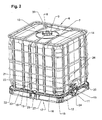
- the used as disposable and reusable container transport and Storage container 6 according to Figures 2 and 3 for liquids and Bulk goods have as main components a replaceable, cuboid inner container 7 made of plastic, with a with a cover 9 closable filler 8 in the upper floor 10 and a discharge nozzle 11 in the region of the lower floor 12th is equipped for connection of a withdrawal and rinsing tap 13, a formed as a mesh basket 14 outer shell of itself crossing horizontal and vertical bars 15, 16 off Metal and a pallet-like base 17 made of metal with euronormroughen length and width dimensions.
- the handling by means of lift truck, storage and retrieval unit and furnished like means of transport, pallet-like Undercarriage 17 of the transport and storage container 6 has a bottom 18 made of sheet metal for supporting the inner container 7.
- Der Floor 18 of the undercarriage 17 rests on four corner feet 19 - 22 and a rear metatarsal 23 made of sheet metal, a front, from the Bottom 18 shaped metatarsus 24, which is below the extraction and Rinse valve 13 of the inner container 7 is arranged, as well as on two lateral middle feet 25, 26.
- Corner and middle feet 19 - 26 of the undercarriage 17 are mounted on a foot frame 27.
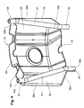
- the corner foot 19 of the undercarriage 17 of the transport and Storage container 6 is characterized by a curved tray plate 28 with an upper support edge 29 for Support of the outer edge 30 of the flat trough-like bottom 18th the lower frame 17 and the lower frame 31 of the grid basket 14 trained outer sheath and a lower Aufstandsrand 32 formed with which the Eckfuß 19 on the Foot frame 27 of the undercarriage 17 is.
- a curved tray plate 28 with an upper support edge 29 for Support of the outer edge 30 of the flat trough-like bottom 18th the lower frame 17 and the lower frame 31 of the grid basket 14 trained outer sheath and a lower Aufstandsrand 32 formed with which the Eckfuß 19 on the Foot frame 27 of the undercarriage 17 is.
- Eckfußes 19 are the pipe sections 37 each having an upper and a lower Rivet shaft 34, 35 welded to the tray plate 28.
- Eckfußes 19 shows the upper rivet shanks 34, 34 on the two outer ones Edges 28a, 28b of a shell plate 28 and the lower Rivet shanks 35, 35 at two of the edges 28 a, 28 b of the Tray plate 28 inwardly angled, outer legs 44, 45th rolled.
- the upper and lower rivet shanks 34, 35 to the shell plate 28 and to be welded to the legs 44, 45.
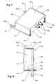
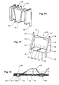
- the lateral middle feet 25, 26, one of which 25 in the Figures 7 to 9 is shown, and the rear metatarsus 23rd of the undercarriage 17 have the shape of an open box 46th with an upper, a support surface 28 having wall 47 and a bottom wall 49 having a footprint 50, two to the both side walls 51, 52 of the box 46 rolled pipe sections 53, 53, each having a lower rivet shank 35 and two upper ones to the support surface 48 of the upper box wall 47 rolled Rivet shafts 34, 34.
- the middle feet 23, 25, 26 are by means of the upper and lower rivet shanks 34, 35, the free ends 34a, 35a are deformable to closing heads 43, in the same way like the corner feet 19-22 with the outer edge 30 of the bottom 18 and the resting on this sub-frame 31 of the mesh basket 14 and the foot frame 27 riveted.
- the lower wall 49 of the two lateral middle feet 25, 26th has on the inside a support surface 54 for each one of the two downwardly bent outer ends 56 of a central stiffening web 55 of the underbody floor 18, and from the lower box wall 49 of the middle feet 25, 26 are two inwardly directed, hollow rivet shanks 57, 58 for riveting the middle feet with the ends 56 of the stiffening web 55 of the Underframe bottom 18 formed ( Figures 3, 7-9).
- the lateral middle feet 25, 26 with the ends 56 of the stiffening web 55 of the Underframe bottom 18 by a known as clinching Joining methods are interconnected. Furthermore, there is the Possibility of riveting shanks 34, 35, 57, 58 as separate To weld sleeves to the side middle feet 25, 26.
- FIG. 10 shows a lateral midfoot 25 of FIG Underframe 17 with a segmented, one-piece box shape 46th
- the lateral metatarsus 25 of FIG Undercarriage 17 has the shape of an open box 46 with an upper, a support surface 48 having wall 47 and a bottom wall 49 with a footprint 50 and two at the two bevelled side walls 51, 52 of the box 46th Rolled pipe sections 53, 53 with two bent ends, the each form an upper and a lower rivet shank 34, 35.
- the bottom wall 49 of the lateral metatarsus 25 has a inner support surface 54 for one of the two ends 56 of the central stiffening web 55 of the undercarriage floor 18 as well two rivet shanks 57, 58 for riveting the metatarsus with a End 56 of the stiffening web 55 on.
- FIG. 12 are used to connect the subframe 31 of Grid basket 14 with the base floor 18 on both sides of the front, with the ground one-piece manufactured metatarsal 24th two each formed from the sub-frame 31, hollow Rivet shanks 59, 59, by rivet holes 40 in the outer edge 30th the bottom 18 pushed through and the free ends 59a means a riveting tool against the bottom 60 of the bottom edge 30th are deformed to closing heads 43.
- rivet shanks 59 can be used for riveting the Sub-frame of the mesh basket with the base frame 18th separate hollow rivets are used.
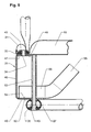
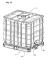
- FIG. 13 shows a transport and storage container 6 for Liquids whose base 17 with wooden skids 62nd equipped.
Landscapes
- Engineering & Computer Science (AREA)
- Mechanical Engineering (AREA)
- General Engineering & Computer Science (AREA)
- Pallets (AREA)
- Connection Of Plates (AREA)
- Rigid Containers With Two Or More Constituent Elements (AREA)
- Packages (AREA)
- Insertion Pins And Rivets (AREA)
- Packaging Of Annular Or Rod-Shaped Articles, Wearing Apparel, Cassettes, Or The Like (AREA)
- Joining Of Building Structures In Genera (AREA)
Abstract
Die Hohlnietverbindung zweier Bauteile (1,2) aus Blech weist
einen an das erste Bauteil (1) angeformten Nietschaft (3) zum
Durchstecken durch ein Nietloch (4) des mit dem ersten Bauteil
(1) zu verbindenden zweiten Bauteils (2) auf, das an dem ersten
Bauteil (1) anliegt. Beim Vernieten der beiden Bauteile (1,2)
wird das durch das Nietloch (4) im zweiten Bauteil (2)
durchgesteckte und über dieses vorstehende freie Ende des
Nietschaftes (3) mittels eines Nietwerkzeuges zu einem
Schließkopf (5) verformt.

Description
Die Erfindung betrifft eine Hohlnietverbindung zum Verbinden eines Bauteils aus Metall oder Kunststoff mit einem Bauteil aus Metall, Kunststoff oder Holz, insbesondere für die Montage von Transport- und Lagerbehältern für Flüssigkeiten und Schüttgut, die mit einem palettenartigen Untergestell, einem auf diesem stehenden Innenbehälter aus Kunststoff mit einem verschließbaren Einfüllstutzen und einem Entleerstutzen zum Anschluß einer Entnahmearmatur sowie einem als Gitter- oder Blechmantel ausgebildeten Außenmantel ausgestattet sind, wobei das Untergestell aus Blech, Kunststoff oder Holz einen Boden zum Abstützen des Innenbehälters sowie Eck- und Mittelfüße aufweist, die auf einem Fußrahmen oder Kufen angebracht sind und an denen der Boden des Untergestells sowie der Außenmantel des Innenbehälters befestigt sind.The invention relates to a Hohlnietverbindung for connecting a component made of metal or plastic with a component Metal, plastic or wood, in particular for the assembly of Transport and storage containers for liquids and bulk materials, those with a pallet base, one on top of this standing inner container made of plastic with a closable Filler neck and a discharge nozzle for connection of a Removal fitting as well as a grid or metal jacket trained outer jacket are equipped, the Base made of sheet metal, plastic or wood a floor to Supporting the inner container as well as corner and middle feet, which are mounted on a foot frame or skids and on which the bottom of the underframe and the outer jacket of the Inner container are attached.
Bei der Montage von aus der DE 100 62 088 C2 bekannten Transport- und Lagerbehältern für Flüssigkeiten der vorstehend beschriebenen Art werden der Unterrahmen des Gitterkorbs aus Metall und der Blechboden des palettenartigen Untergestells, auf dem der Kunststoff-Innenbehälter für Flüssigkeiten steht, mit den Eck- und Mittelfüßen des Untergestells verschraubt und die Füße werden mit dem Fußrahmen des Untergestells verschweißt. Durch die Anwendung unterschiedlicher Verbindungstechniken und den dadurch bedingten erheblichen Montageaufwand sowie den Bedarf an Kleinteilen für die Montage wie Blechschrauben und Unterlegscheiben werden die Herstellungskosten der Flüssigkeitsbehälter entsprechend verteuert.In the assembly of known from DE 100 62 088 C2 Transport and storage containers for liquids of the above described type of sub-frame of the mesh basket Metal and the sheet metal floor of the pallet base, on which is the plastic inner container for liquids, with the corner and middle feet of the base bolted and the Feet are welded to the foot frame of the undercarriage. Through the use of different connection techniques and the consequent considerable installation effort and the Need for small parts for assembly such as tapping screws and Washers are the manufacturing cost of Liquid container correspondingly more expensive.
Der Erfindung liegt die Aufgabe zugrunde, eine Verbindungstechnik für Werkstücke und Bauteile aus Metall, Kunststoff oder Holz zu entwickeln, die eine vereinfachte Montage von Gegenständen und Einrichtungen unterschiedlicher Art ermöglicht.The invention is based on the object Connection technology for workpieces and components made of metal, To develop plastic or wood that is a simplified one Assembly of objects and equipment of different kinds allows.
Diese Aufgabe ist erfindungsgemäß gelöst durch eine
Hohlnietverbindung mit den Merkmalen des Patentanspruchs 1.This object is achieved by a
Hohlnietverbindung with the features of
Die Unteransprüche beinhalten die Ausstattung der einzelnen
Bauteile eines Transport- und Lagerbehälters für Flüssigkeiten
gemäß dem Oberbegriff des Patentanspruchs 1 mit der
erfindungsgemäßen Hohlnietverbindung.The dependent claims include the equipment of each
Components of a transport and storage container for liquids
according to the preamble of
Der Erfindungsgedanke beruht darauf, Hohlniete und entsprechende Nietlöcher in Werkstücke und Bauteile unterschiedlicher Art aus Metall, Kunststoff oder Holz zu integrieren, so daß zur Verbindung der Werkstücke und Bauteile bei der Montage lediglich eine Fügetechnik, nämlich das Nieten zur Anwendung gelangt und gesonderte Hohlniete mit einem Setzkopf nicht mehr erforderlich sind. Auf diese Weise wird der Montageaufwand verringert und die Herstellungskosten werden gesenkt.The idea of the invention is based on hollow rivets and corresponding rivet holes in workpieces and components different kind of metal, plastic or wood too integrate, so that for the connection of workpieces and components during assembly, only one joining technique, namely riveting comes to use and separate hollow rivets with a Setting head are no longer necessary. In this way, the Assembly costs are reduced and the production costs lowered.
Die Erfindung ist nachstehend anhand von Zeichnungsfiguren erläutert, die folgendes darstellen:
- Fig. 1a
- eine schematische Schnittdarstellung eine Hohlnietverbindung von zwei Bauteilen aus Blech gemäß Linie Ia-Ia der Figur 1b,
- Fig. 1b
- eine Draufsicht der Hohlnietverbindung nach Fig. 1a,
- Fig. 1c
- eine Seitenansicht des ersten Bauteils mit einem angeformten Nietschaft,
- Fig. 2
- eine perspektivische Darstellung eines Transport- und Lagerbehälters für Flüssigkeiten mit einem palettenartigen Untergestell aus Metall,
- Fig. 3
- eine Sprengdarstellung des Transport- und Lagerbehälters nach Fig. 2 ohne Innenbehälter,
- Fig. 4
- eine perspektivische Innenansicht einer ersten Ausführungsform eines Eckfußes des Untergestells des Transport- und Lagerbehälters in vergrößerter Darstellung,
- Fig. 5
- eine vergrößerte Schnittdarstellung der Hohlnietverbindungen des Eckfußes nach Fig. 4 mit dem äußeren Rand des Bodens des Untergestells und dem Unterrahmen des Gitterkorbs sowie dem Fußrahmen des Untergestells,
- Fig. 6
- eine perspektivische Innenansicht einer weiteren Ausführungsform eines Eckfußes des Untergestells des Transport- und Lagerbehälters in vergrößerter Darstellung,
- Fig. 7
- eine perspektivische Ansicht einer ersten Ausführungsform eines seitlichen Mittelfußes des Untergestells des Transport- und Lagerbehälters in vergrößerter Darstellung,
- Fig. 8
- eine Seitenansicht des seitlichen Mittelfußes nach Fig. 7,
- Fig. 9
- eine vergrößerte Schnittdarstellung der
Hohlnietverbindungen des Mittelfußes nach den
Figuren 7 und 8 mit dem äußeren Rand des Bodens des Untergestells und dem Unterrahmen des Gitterkorbs sowie dem Fußrahmen des Untergestells, - Fig. 10
- eine perspektivische Ansicht einer weiteren Ausführungsform eines Mittelfußes des Untergestells des Transport- und Lagerbehälters in vergrößerter Darstellung,
- Fig. 11
- eine perspektivische Innenansicht einer dritten Ausführungsform eines Mittelfußes des Untergestells in vergrößerter Darstellung,
- Fig. 12
- die Hohlnietverbindungen des Unterrahmens des Gitterkorbs mit dem äußeren Rand des Bodens des Untergestells im Bereich der vorderen Auslaufmulde in vergrößerter Darstellung,
- Fig. 13
- eine perspektivische Darstellung eines Transport- und Lagerbehälters mit einem mit Holzkufen ausgestatteten Untergestell und
- Fig. 14
- eine perspektivische Schnittdarstellung der Holznietverbindungen eines seitlichen Mittelfußes mit dem äußeren Rand des Bodens des Untergestells und dem Unterrahmen des Gitterkorbs sowie mit einer Holzkufe des Untergestells des Behälters nach Fig. 13.
- Fig. 1a
- 1 is a schematic sectional view of a hollow rivet connection of two sheet metal components according to line Ia-Ia of FIG. 1b;
- Fig. 1b
- a top view of the hollow rivet connection according to Fig. 1a,
- Fig. 1c
- a side view of the first component with a molded rivet shank,
- Fig. 2
- a perspective view of a transport and storage container for liquids with a pallet-like base made of metal,
- Fig. 3
- an exploded view of the transport and storage container of FIG. 2 without inner container,
- Fig. 4
- an interior perspective view of a first embodiment of a Eckfußes of the undercarriage of the transport and storage container in an enlarged view,
- Fig. 5
- an enlarged sectional view of the Hohlnietverbindungen the Eckfußes of Figure 4 with the outer edge of the bottom of the base frame and the lower frame of the mesh basket and the base frame of the base,
- Fig. 6
- an internal perspective view of another embodiment of a Eckfußes of the undercarriage of the transport and storage container in an enlarged view,
- Fig. 7
- a perspective view of a first embodiment of a lateral metatarsal of the undercarriage of the transport and storage container in an enlarged view,
- Fig. 8
- a side view of the lateral metatarsus of FIG. 7,
- Fig. 9
- an enlarged sectional view of the Hohlnietverbindungen the metatarsus of Figures 7 and 8 with the outer edge of the bottom of the base frame and the lower frame of the mesh basket and the base frame of the undercarriage,
- Fig. 10
- a perspective view of another embodiment of a metatarsus of the undercarriage of the transport and storage container in an enlarged view,
- Fig. 11
- an interior perspective view of a third embodiment of a metatarsus of the underframe in an enlarged view,
- Fig. 12
- the Hohlnietverbindungen the sub-frame of the mesh basket with the outer edge of the bottom of the underframe in the region of the front outlet trough in an enlarged view,
- Fig. 13
- a perspective view of a transport and storage container with a wooden skids equipped base and
- Fig. 14
- a perspective sectional view of the Holznietverbindungen a lateral metatarsal with the outer edge of the bottom of the base frame and the lower frame of the mesh basket and with a wooden skid of the underframe of the container of FIG .. 13
Die in den Figuren 1a bis 1c dargestellte Hohlnietverbindung
zweier Bauteile 1, 2 aus Blech weist einen an das erste Bauteil
1 angeformten Nietschaft 3 zum Durchstecken durch ein Nietloch 4
des mit dem ersten Bauteil 1 zu verbindenden zweiten Bauteils 2
auf, das an dem ersten Bauteil 1 anliegt. Beim Vernieten der
beiden Bauteile 1, 2 wird das durch das Nietloch 4 im zweiten
Bauteil 2 durchgesteckte und über dieses vorstehende freie Ende
3a des Nietschaftes 3 mittels eines Hammers oder eines
besonderen Nietwerkzeugs zu einem an dem zweiten Bauteil 2
anliegenden Schließkopf 5 verformt.The Hohlnietverbindung shown in Figures 1a to 1c
two
Der Nietschaft 3 kann beispielsweise mit einem Schieber an
das erste Bauteil 1 angerollt werden.The
Bei einer abgeänderten Ausführungsform der vorbeschriebenen
Hohlnietverbindung wird der Nietschaft 3 als gesondertes Bauteil
an das erste Bauteil 1 angeschweißt.In a modified embodiment of the above
Hohlnietverbindung the
Nachstehend ist die Anwendung der erfindungsgemäßen Hohlnietverbindung zur Montage der einzelnen Bauteile von Transport- und Lagerbehältern für Flüssigkeiten erläutert.Below is the application of the invention Hohlnietverbindung for mounting the individual components of Transport and storage containers for liquids explained.
Der als Ein- und Mehrwegbehälter verwendete Transport- und
Lagerbehälter 6 nach den Figuren 2 und 3 für Flüssigkeiten und
Schüttgut weist als Hauptbauteile einen austauschbaren,
quaderförmigen Innenbehälter 7 aus Kunststoff, der mit einem mit
einem Deckel 9 verschließbaren Einfüllstutzen 8 im oberen Boden
10 und einem Entleerstutzen 11 im Bereich des unteren Bodens 12
zum Anschluß eines Entnahme- und Spülhahns 13 ausgestattet ist,
einen als Gitterkorb 14 ausgebildeten Außenmantel aus sich
kreuzenden waagrechten und senkrechten Gitterstäben 15, 16 aus
Metall sowie ein palettenartiges Untergestell 17 aus Metall mit
euronormgerechten Längen- und Breitenabmessungen auf.The used as disposable and reusable container transport and
Das zur Handhabung mittels Hubstapler, Regalbediengerät und
dergleichen Transportmitteln eingerichtete, palettenartige
Untergestell 17 des Transport- und Lagerbehälters 6 besitzt
einen Boden 18 aus Blech zum Abstützen des Innenbehälters 7. Der
Boden 18 des Untergestells 17 ruht auf vier Eckfüßen 19 - 22 und
einem hinteren Mittelfuß 23 aus Blech, einem vorderen, aus dem
Boden 18 ausgeformten Mittelfuß 24, der unterhalb des Entnahme-und
Spülhahns 13 des Innenbehälters 7 angeordnet ist, sowie auf
zwei seitlichen Mittelfüßen 25, 26. Eck- und Mittelfüße 19 - 26
des Untergestells 17 sind auf einem Fußrahmen 27 befestigt.The handling by means of lift truck, storage and retrieval unit and
furnished like means of transport, pallet-
Der Eckfuß 19 des Untergestells 17 des Transport- und
Lagerbehälters 6 gemäß den Figuren 4 und 5 wird durch ein
gewölbtes Schalenblech 28 mit einem oberen Abstützrand 29 zur
Auflage des äußeren Randes 30 des flachwannenartigen Bodens 18
des Untergestells 17 und des Unterrahmens 31 des als Gitterkorb
14 ausgebildeten Außenmantels sowie mit einem unteren
Aufstandsrand 32 gebildet, mit dem der Eckfuß 19 auf dem
Fußrahmen 27 des Untergestells 17 steht. Beim
Übereinanderstapeln mehrerer Transportbehälter 6 stützt sich der
jeweils aufgestapelte Transportbehälter mit dem unteren
Aufstandsrand 32 der Eckfüße 19 - 22 auf dem Oberrahmen 33 des
Gitterkorbs 14 des jeweils untergestapelten Transportbehälters
ab.The
An den beiden äußeren Abschnitten 29a, 29b des oberen
Abstützrandes 29 des Schalenblechs 28 des Eckfußes 19 sind zwei
obere, hohle Nietschäfte 34, 34 und an den beiden äußeren
Abschnitten 32a, 32b des unteren Aufstandsrandes 32 des
Schalenblechs 28 zwei untere, hohle Nietschäfte 35, 35
angeordnet. Die oberen und unteren Nietschäfte 34, 35 stehen
nach oben bzw. unten über den Eckfuß 19 vor. Die unteren
Nietschäfte 35, 35 an dem Schalenblech 28 des Eckfußes 19 sind
zu den oberen Nietschäften 34, 34 parallel nach innen und in
Vertikalrichtung entsprechend dem Vertikalabstand 36 des oberen
Abstützrandes 29 und des unteren Aufstandsrandes 32 des Eckfußes
19 gegeneinander versetzt angeordnet.At the two
Jeweils ein oberer und ein unterer Nietschaft 34, 35 des
Eckfußes 19 sind durch die beiden abgebogenen Enden eines
Rohrstücks 37 gebildet, wobei die Rohrstücke 37, 37 an zwei von
den äußeren Rändern 28a, 28b des Schalenblechs 28 des Eckfußes
19 nach innen abgewinkelte, abgeschrägte, äußere Schenkel 38, 39
angeformt, vorzugsweise angerollt sind.In each case an upper and a
Bei einer abgeänderten Ausführungsform des Eckfußes 19 sind
die Rohrstücke 37 mit jeweils einem oberen und einem unteren
Nietschaft 34, 35 an das Schalenblech 28 angeschweißt.In a modified embodiment of the
Durch die an der Innenseite der äußeren Schenkel 38, 39 des
Eckfußes 19 angerollten Rohrstücke 37 mit jeweils einem oberen
und einem unteren Nietschaft 34, 35 werden die Schenkel 38, 39
des Eckfußes 19 versteift. Durch diese Versteifung wird eine
Beschädigung der Eckfüße 19 - 22 beim Unterfahren des
Untergestells 17 eines Transport- und Lagerbehälters 6 und einem
Verschieben des Behälters durch die Greifarme eines
Transportfahrzeuges, beispielsweise eines Gabelsteplers
vermieden.By on the inside of the
Bei der Montage des Untergestells 17 und des Gitterkorbs 14
eines Transport- und Lagerbehälters 6 werden die oberen
Nietschäfte 34 der Eckfüße 19 - 22 durch entsprechende
deckungsgleiche Nietlöcher 40, 41 im äußeren Rand 30 des Bodens
18 und in dem im Bereich der Nietlöcher 41 abgeflachten
Unterrahmen 31 des Gitterkorbs 14 durchgesteckt und der mit
entsprechenden Nietlöchern 42 versehene, im Bereich derselben
abgeflachte Fußrahmen 27 des Untergestells 17 wird auf die
unteren Nietschäfte 35 der Eckfüße 19 - 22 aufgesetzt.
Anschließend werden die über den im Bereich der Nietlöcher 41
abgeflachten Unterrahmen 31 des Gitterkorbs 14 vorstehenden,
freien Enden 34a der oberen Nietschäfte 34 und die über den im
Bereich der Nietlöcher 42 abgeflachten Fußrahmen 27 des
Untergestells 17 vorstehenden unteren Nietschäfte 35 der Eckfüße
19 - 22 mit einem Nietwerkzeug zu Schließköpfen 43 verformt und
damit die Eckfüße 19 - 22 einerseits mit dem Boden 18 und dem
Unterrahmen 31 des Gitterkorbs 14 und andererseits mit dem
Fußrahmen 27 fest vernietet.When mounting the
Bei einer weiteren Ausführungsform eines Eckfußes 19 gemäß
Figur 6 sind die oberen Nietschäfte 34, 34 an die beiden äußeren
Ränder 28a, 28b eines Schalenblechs 28 und die unteren
Nietschäfte 35, 35 an zwei von den Ränder 28a, 28b des
Schalenblechs 28 nach innen abgewinkelte, äußere Schenkel 44, 45
angerollt.In a further embodiment of a
Ferner besteht die Möglichkeit, bei dem Eckfuß 19 nach Fig.
6 die oberen und unteren Nietschäfte 34, 35 an das Schalenblech
28 und an dessen Schenkel 44, 45 anzuschweißen.It is also possible, in the
Die seitlichen Mittelfüße 25, 26, von denen einer 25 in den
Figuren 7 bis 9 dargestellt ist, und der hintere Mittelfuß 23
des Untergestells 17 besitzen die Form eines offenen Kastens 46
mit einer oberen, eine Abstützfläche 28 aufweisenden Wand 47 und
einer unteren Wand 49 mit einer Aufstandsfläche 50, zwei an die
beiden Seitenwände 51, 52 des Kastens 46 angerollten Rohrstücken
53, 53 mit jeweils einem unteren Nietschaft 35 und zwei oberen
an die Abstützfläche 48 der oberen Kastenwand 47 angerollten
Nietschäften 34, 34. Die Mittelfüße 23, 25, 26 werden mittels
der oberen und unteren Nietschäfte 34, 35, deren freie Enden
34a, 35a zu Schließköpfen 43 verformbar sind, in gleicher Weise
wie die Eckfüße 19 - 22 mit dem äußeren Rand 30 des Bodens 18
und dem auf diesem aufliegenden Unterrahmen 31 des Gitterkorbs
14 sowie dem Fußrahmen 27 vernietet.The lateral
Die untere Wand 49 der beiden seitlichen Mittelfüße 25, 26
besitzt auf der Innenseite eine Abstützfläche 54 für jeweils
eines der beiden nach unten abgebogenen äußeren Enden 56 eines
mittigen Versteifungssteges 55 des Untergestellbodens 18, und
aus der unteren Kastenwand 49 der Mittelfüße 25, 26 sind zwei
nach innen gerichtete, hohle Nietschäfte 57, 58 zum Vernieten
der Mittelfüße mit den Enden 56 des Versteifungssteges 55 des
Untergestellbodens 18 ausgeformt (Fign. 3, 7-9).The
Anstatt durch Nieten können die seitlichen Mittelfüße 25, 26
mit den Enden 56 des Versteifungssteges 55 des
Untergestellbodens 18 durch ein als Durchsetzfügen bekanntes
Fügeverfahren miteinander verbunden werden. Ferner besteht die
Möglichkeit, die Nietschäfte 34, 35, 57, 58 als gesonderte
Hülsen an die seitlichen Mittelfüße 25, 26 anzuschweißen.Instead of riveting, the lateral
Figur 10 zeigt einen seitlichen Mittelfuß 25 des
Untergestells 17 mit einer segmentierten, einteiligen Kastenform
46.FIG. 10 shows a
Der in Figur 11 dargestellte seitliche Mittelfuß 25 des
Untergestells 17 besitzt die Form eines offenen Kastens 46 mit
einer oberen, eine Abstützfläche 48 aufweisenden Wand 47 und
einer unteren Wand 49 mit einer Aufstandsfläche 50 sowie zwei an
die beiden abgeschrägten Seitenwände 51, 52 des Kastens 46
angerollten Rohrstücken 53, 53 mit zwei abgebogenen Enden, die
jeweils einen oberen und einen unteren Nietschaft 34, 35 bilden.
Die untere Wand 49 des seitlichen Mittelfußes 25 weist eine
innere Abstützfläche 54 für eines der beiden Enden 56 des
mittigen Versteifungssteges 55 des Untergestellbodens 18 sowie
zwei Nietschäfte 57, 58 zum Vernieten des Mittelfußes mit einem
Ende 56 des Versteifungssteges 55 auf.The
Gemäß Figur 12 dienen zur Verbindung des Unterrahmens 31 des
Gitterkorbs 14 mit dem Untergestellboden 18 beidseits des
vorderen, mit dem Boden einteilig gefertigten Mittelfußes 24
jeweils zwei aus dem Unterrahmen 31 ausgeformte, hohle
Nietschäfte 59, 59, die durch Nietlöcher 40 im äußeren Rand 30
des Bodens 18 durchgesteckt und deren freie Enden 59a mittels
eines Nietwerkzeuges gegen die Unterseite 60 des Bodenrandes 30
zu Schließköpfen 43 verformt sind.According to Figure 12 are used to connect the
Anstatt von aus dem Unterrahmen 31 des Gitterkorbs 14
ausgeformten Nietschäften 59 können zum Vernieten des
Unterrahmens des Gitterkorbs mit dem Untergestellboden 18
gesonderte Hohlniete verwendet werden.Instead of from the
Gemäß Figur 3 ist der vordere Mittelfuß 24 des Untergestells
17 mittels eines Hohlniets 61 mit Setzkopf auf dem Fußrahmen 27
befestigt.According to Figure 3, the
Figur 13 zeigt einen Transport- und Lagerbehälter 6 für
Flüssigkeiten, dessen Untergestell 17 mit Holzkufen 62
ausgerüstet ist.FIG. 13 shows a transport and
Zur Befestigung des in Figur 14 dargestellten seitlichen
Mittelfußes 25 des Untergestells 17 auf einer Holzkufe 62 des
Untergestells 17 werden die beiden unteren Nietschäfte 35 des
Mittelfußes 25 durch entsprechende Senkbohrungen 63 der Holzkufe
62 durchgesteckt. Anschließend kann jeweils eine Unterlegscheibe
64 auf die freien, über die Holzkufe 62 vorstehenden Enden 35a
der Nietschäfte 35 aufgeschoben werden und danach werden die
Enden 35a der Nietschäfte 35 mittels eines Nietwerkzeugs zu
Schließköpfen 43 verformt, die in der Vertiefung 65 der
Senkbohrungen 63 eingelassen sind.For attachment of the lateral shown in Figure 14
In gleicher Weise werden der zweite seitliche Mittelfuß 26
und der hintere Mittelfuß 23 sowie die vier Eckfüße 19 - 22 auf
den Holzkufen 62 des Untergestells 17 angebracht. Zur
Befestigung des vorderen Mittelfußes 24 auf der mittleren
Holzkufe 62 des Untergestells 17 wird ein Hohlniet mit Setzkopf
verwendet.In the same way, the second
Claims (10)
Priority Applications (1)
| Application Number | Priority Date | Filing Date | Title |
|---|---|---|---|
| PL05003552T PL1568896T3 (en) | 2004-02-27 | 2005-02-18 | Middle and/or corner legs of sheet metal for transport and storage containers for liquids and bulk materials |
Applications Claiming Priority (2)
| Application Number | Priority Date | Filing Date | Title |
|---|---|---|---|
| DE202004003020U | 2004-02-27 | ||
| DE202004003020U DE202004003020U1 (en) | 2004-02-27 | 2004-02-27 | Hollow rivet connection for components made of metal, plastic or wood, in particular for the assembly of transport and storage containers for liquids |
Publications (3)
| Publication Number | Publication Date |
|---|---|
| EP1568896A2 true EP1568896A2 (en) | 2005-08-31 |
| EP1568896A3 EP1568896A3 (en) | 2007-03-28 |
| EP1568896B1 EP1568896B1 (en) | 2015-01-28 |
Family
ID=32240902
Family Applications (1)
| Application Number | Title | Priority Date | Filing Date |
|---|---|---|---|
| EP05003552.6A Expired - Lifetime EP1568896B1 (en) | 2004-02-27 | 2005-02-18 | Middle and/or corner legs of sheet metal for transport and storage containers for liquids and bulk materials |
Country Status (15)
| Country | Link |
|---|---|
| US (1) | US7866501B2 (en) |
| EP (1) | EP1568896B1 (en) |
| JP (1) | JP4101244B2 (en) |
| CN (1) | CN100534873C (en) |
| AR (1) | AR047979A1 (en) |
| AU (1) | AU2005200863B2 (en) |
| BR (1) | BRPI0500564A (en) |
| DE (2) | DE202004003020U1 (en) |
| ES (1) | ES2535432T3 (en) |
| MX (1) | MXPA05002155A (en) |
| MY (1) | MY140586A (en) |
| NO (1) | NO337431B1 (en) |
| PL (1) | PL1568896T3 (en) |
| RU (1) | RU2288379C1 (en) |
| ZA (1) | ZA200501451B (en) |
Cited By (1)
| Publication number | Priority date | Publication date | Assignee | Title |
|---|---|---|---|---|
| EP1982924A1 (en) * | 2007-04-18 | 2008-10-22 | Daviplast - Servicos de Consultoria, Sociedade Unipessoal LDA. | Pallet container |
Families Citing this family (19)
| Publication number | Priority date | Publication date | Assignee | Title |
|---|---|---|---|---|
| DE102004058252B4 (en) * | 2004-08-14 | 2010-03-25 | Protechna S.A. | Union nut made of plastic |
| DE202004014102U1 (en) * | 2004-09-08 | 2004-11-04 | Mauser-Werke Gmbh & Co. Kg | pallet container |
| TWI290397B (en) * | 2005-11-14 | 2007-11-21 | Hon Hai Prec Ind Co Ltd | Method of assembling an electrical connector |
| DE102009040102B4 (en) * | 2009-09-04 | 2011-07-07 | Miele & Cie. KG, 33332 | Rivet and basket insert |
| DE102010040270A1 (en) * | 2010-09-06 | 2012-03-08 | Protechna S.A. | Transport and storage container for liquids |
| DE102010048609B4 (en) * | 2010-10-15 | 2013-06-27 | Ekkehard Schneider | Container arrangement with stiffening element |
| DE102011007587A1 (en) * | 2011-04-18 | 2012-10-18 | Protechna S.A. | Pallet-type base for transport and storage containers for liquids |
| DE102011007583B4 (en) * | 2011-04-18 | 2015-07-09 | Protechna S.A. | Pallet-type base for transport and storage containers for liquids |
| CN102228880A (en) * | 2011-06-18 | 2011-11-02 | 津伦(天津)精密机械股份有限公司 | Workpiece holding basket capable of overturning and reversely loading and unloading workpieces |
| US9802732B2 (en) | 2014-09-08 | 2017-10-31 | Green Ox Pallet Technology, Llc | Lightweight and rigid pallet |
| US9452881B2 (en) * | 2014-11-17 | 2016-09-27 | Mobile Shelter Systems As | Cargo locker with doors |
| PL3400181T3 (en) * | 2016-01-07 | 2020-08-24 | Mauser-Werke Gmbh | Pallet container |
| HRP20220119T1 (en) * | 2016-04-07 | 2022-04-15 | Mauser-Werke Gmbh | Pallet container |
| AU2019231331A1 (en) * | 2018-03-09 | 2020-09-24 | Incitias Pty Ltd | Containment system for storing and transporting bulk liquid |
| DE102018113115B3 (en) * | 2018-06-01 | 2019-09-26 | Protechna S.A. | Transport and storage container for liquids |
| CN110712877B (en) * | 2019-10-30 | 2024-12-06 | 广东新会中集特种运输设备有限公司 | Container floor and container having the same |
| WO2022180128A1 (en) * | 2021-02-24 | 2022-09-01 | Illucens Gmbh | Handling device and method used in insect breeding |
| DE102021121667A1 (en) | 2021-08-20 | 2023-02-23 | Protechna S.A. | Pallet-like underframe for a transport and storage container and assembly kit for producing such an underframe and transport and storage container with such an underframe |
| DE102023111043A1 (en) * | 2023-04-28 | 2024-10-31 | Protechna S.A. | Pallet-like underframe for a transport and storage container as well as transport and storage containers with such an underframe |
Citations (1)
| Publication number | Priority date | Publication date | Assignee | Title |
|---|---|---|---|---|
| DE10062088C2 (en) | 2000-12-06 | 2002-10-24 | Protechna Sa | Pallet-like base for transport and storage containers for liquids |
Family Cites Families (16)
| Publication number | Priority date | Publication date | Assignee | Title |
|---|---|---|---|---|
| US3952913A (en) * | 1974-11-18 | 1976-04-27 | Continental Can Company, Inc. | Tab anti-rotation and hold down device |
| US4010519A (en) * | 1975-11-24 | 1977-03-08 | Shur-Lok Corporation | Fastener structures utilizing a thermoplastic adhesive |
| DE3639870A1 (en) * | 1986-11-21 | 1988-06-01 | Daimler Benz Ag | SECURITY DEVICE FOR DETECTING THE UNAUTHORIZED OPENING OF A HOUSING |
| DD260737A1 (en) * | 1987-05-21 | 1988-10-05 | Goerlitz Waggonbau Veb | METHOD FOR CONNECTING A VARIETY OF NATURAL BUILDING COMPONENTS |
| FR2619169B1 (en) * | 1987-08-07 | 1989-10-06 | Tubauto | METHOD AND DEVICE FOR THE QUICK CONNECTION OF TWO PARTS HAVING, IN GENERAL, PLANAR OVERLAY AREAS |
| DE4206945C1 (en) * | 1991-03-15 | 1993-03-11 | Schuetz-Werke Gmbh & Co. Kg, 5418 Selters, De | |
| US5285873A (en) * | 1992-02-19 | 1994-02-15 | Ray Arbesman | Disk brake friction assembly |
| ES2104159T3 (en) * | 1992-07-30 | 1997-10-01 | Splitfast Technologies Limited | WELDING PINS, WELDING APPARATUS FOR WELDING A FIXING ELEMENT AND PROCEDURE FOR FIXING A MOUNTING PART ON A WELDED FIXING ELEMENT. |
| DE4325223C1 (en) * | 1993-07-28 | 1995-01-12 | Schuetz Werke Gmbh Co Kg | Pallet container |
| DE4341539C2 (en) * | 1993-12-06 | 1998-07-09 | Protechna Sa | Containers for the transport and storage of liquids |
| JP2001500460A (en) * | 1996-09-19 | 2001-01-16 | ロート ヴエルケ ゲゼルシヤフト ミツト ベシユレンクテル ハフツング | Pallet container |
| DE10027422A1 (en) * | 2000-06-02 | 2002-06-06 | Ina Schaeffler Kg | rivet |
| BR0115561B1 (en) * | 2000-11-23 | 2012-09-04 | Palette container. | |
| DE20217856U1 (en) * | 2002-11-19 | 2003-02-13 | Protechna S.A., Freiburg/Fribourg | Pallet-like base, especially for transport and storage containers for liquids |
| DE10301517B3 (en) * | 2003-01-17 | 2004-03-11 | Protechna S.A. | Transport and storage container for liquid has vertical grid rods of grid mantle enclosing inner plastics container welded to upper edge profile supporting stacked container |
| DE20316883U1 (en) * | 2003-10-31 | 2004-03-11 | Protechna S.A. | Pallet-type base for transport and storage containers for liquids |
-
2004
- 2004-02-27 DE DE202004003020U patent/DE202004003020U1/en not_active Expired - Lifetime
- 2004-07-23 DE DE102004035857A patent/DE102004035857B4/en not_active Expired - Fee Related
-
2005
- 2005-02-17 ZA ZA200501451A patent/ZA200501451B/en unknown
- 2005-02-18 EP EP05003552.6A patent/EP1568896B1/en not_active Expired - Lifetime
- 2005-02-18 US US11/061,851 patent/US7866501B2/en not_active Expired - Fee Related
- 2005-02-18 PL PL05003552T patent/PL1568896T3/en unknown
- 2005-02-18 ES ES05003552.6T patent/ES2535432T3/en not_active Expired - Lifetime
- 2005-02-24 MX MXPA05002155A patent/MXPA05002155A/en active IP Right Grant
- 2005-02-25 RU RU2005105410/11A patent/RU2288379C1/en not_active IP Right Cessation
- 2005-02-25 BR BR0500564-7A patent/BRPI0500564A/en not_active Application Discontinuation
- 2005-02-25 AR ARP050100703A patent/AR047979A1/en not_active Application Discontinuation
- 2005-02-25 JP JP2005049859A patent/JP4101244B2/en not_active Expired - Fee Related
- 2005-02-25 AU AU2005200863A patent/AU2005200863B2/en not_active Ceased
- 2005-02-25 MY MYPI20050776A patent/MY140586A/en unknown
- 2005-02-25 CN CNB2005100528812A patent/CN100534873C/en not_active Expired - Fee Related
- 2005-02-25 NO NO20051026A patent/NO337431B1/en not_active IP Right Cessation
Patent Citations (1)
| Publication number | Priority date | Publication date | Assignee | Title |
|---|---|---|---|---|
| DE10062088C2 (en) | 2000-12-06 | 2002-10-24 | Protechna Sa | Pallet-like base for transport and storage containers for liquids |
Cited By (2)
| Publication number | Priority date | Publication date | Assignee | Title |
|---|---|---|---|---|
| EP1982924A1 (en) * | 2007-04-18 | 2008-10-22 | Daviplast - Servicos de Consultoria, Sociedade Unipessoal LDA. | Pallet container |
| US7878327B2 (en) | 2007-04-18 | 2011-02-01 | Daviplast-Servicos de Consultoria, Sociedade Unipessoal Ltd. | Pallet container |
Also Published As
| Publication number | Publication date |
|---|---|
| DE102004035857A1 (en) | 2005-09-22 |
| CN1664387A (en) | 2005-09-07 |
| AU2005200863A1 (en) | 2005-09-15 |
| JP4101244B2 (en) | 2008-06-18 |
| MXPA05002155A (en) | 2005-08-31 |
| EP1568896B1 (en) | 2015-01-28 |
| US20050196252A1 (en) | 2005-09-08 |
| BRPI0500564A (en) | 2005-10-18 |
| NO337431B1 (en) | 2016-04-11 |
| DE102004035857B4 (en) | 2006-01-19 |
| EP1568896A3 (en) | 2007-03-28 |
| JP2005246481A (en) | 2005-09-15 |
| PL1568896T3 (en) | 2015-07-31 |
| RU2005105410A (en) | 2006-08-10 |
| NO20051026D0 (en) | 2005-02-25 |
| ZA200501451B (en) | 2005-09-05 |
| MY140586A (en) | 2009-12-31 |
| AR047979A1 (en) | 2006-03-15 |
| ES2535432T3 (en) | 2015-05-11 |
| AU2005200863B2 (en) | 2008-09-25 |
| US7866501B2 (en) | 2011-01-11 |
| NO20051026L (en) | 2005-08-29 |
| RU2288379C1 (en) | 2006-11-27 |
| CN100534873C (en) | 2009-09-02 |
| DE202004003020U1 (en) | 2004-04-29 |
Similar Documents
| Publication | Publication Date | Title |
|---|---|---|
| EP1568896B1 (en) | Middle and/or corner legs of sheet metal for transport and storage containers for liquids and bulk materials | |
| DE602005006153T2 (en) | PALLET FOR STORING AND TRANSPORTING GOODS | |
| EP1439130B1 (en) | Transport- and storage container for liquids | |
| DE4206945C1 (en) | ||
| EP0656299B1 (en) | Metallic container for transporting and storing liquids | |
| DE4124635A1 (en) | ADJUSTABLE BRACKET FOR BASKETS | |
| EP1535858A1 (en) | Pallet like support for transport and storage containers for liquids | |
| DE4341539C2 (en) | Containers for the transport and storage of liquids | |
| EP1754670B1 (en) | Transport and storage container for liquids | |
| EP2010023A1 (en) | Shelf panel | |
| DE60319376T2 (en) | Collapsible container | |
| EP1426299A1 (en) | Stiffening plate for a carrying surface of a pallet | |
| DE19836378C2 (en) | palette | |
| DE10062088C2 (en) | Pallet-like base for transport and storage containers for liquids | |
| CH686360A5 (en) | Plastics storage and transporting container | |
| DE10126065C2 (en) | deformation element | |
| EP2981449B1 (en) | Modular floor for a utility vehicle and method for producing said modular floor | |
| EP1314649B1 (en) | Sheet steel pallet | |
| DE20017697U1 (en) | Box-shaped box with two block-like feet | |
| DE3603434C2 (en) | ||
| DE102019207640B3 (en) | Stacking box | |
| DE19505193A1 (en) | Rectangular storage and transport container for tools and components For building industry | |
| DE19818651A1 (en) | Pallet container for storing and transporting liquids | |
| EP0911269B1 (en) | Pallet with enhanced load capacity | |
| DE102006039758A1 (en) | Load arm for a pallet truck |
Legal Events
| Date | Code | Title | Description |
|---|---|---|---|
| PUAI | Public reference made under article 153(3) epc to a published international application that has entered the european phase |
Free format text: ORIGINAL CODE: 0009012 |
|
| AK | Designated contracting states |
Kind code of ref document: A2 Designated state(s): AT BE BG CH CY CZ DE DK EE ES FI FR GB GR HU IE IS IT LI LT LU MC NL PL PT RO SE SI SK TR |
|
| AX | Request for extension of the european patent |
Extension state: AL BA HR LV MK YU |
|
| PUAL | Search report despatched |
Free format text: ORIGINAL CODE: 0009013 |
|
| AK | Designated contracting states |
Kind code of ref document: A3 Designated state(s): AT BE BG CH CY CZ DE DK EE ES FI FR GB GR HU IE IS IT LI LT LU MC NL PL PT RO SE SI SK TR |
|
| AX | Request for extension of the european patent |
Extension state: AL BA HR LV MK YU |
|
| 17P | Request for examination filed |
Effective date: 20070625 |
|
| AKX | Designation fees paid |
Designated state(s): AT BE BG CH CY CZ DE DK EE ES FI FR GB GR HU IE IS IT LI LT LU MC NL PL PT RO SE SI SK TR |
|
| 17Q | First examination report despatched |
Effective date: 20081203 |
|
| GRAP | Despatch of communication of intention to grant a patent |
Free format text: ORIGINAL CODE: EPIDOSNIGR1 |
|
| INTG | Intention to grant announced |
Effective date: 20140827 |
|
| GRAS | Grant fee paid |
Free format text: ORIGINAL CODE: EPIDOSNIGR3 |
|
| GRAA | (expected) grant |
Free format text: ORIGINAL CODE: 0009210 |
|
| AK | Designated contracting states |
Kind code of ref document: B1 Designated state(s): AT BE BG CH CY CZ DE DK EE ES FI FR GB GR HU IE IS IT LI LT LU MC NL PL PT RO SE SI SK TR |
|
| REG | Reference to a national code |
Ref country code: GB Ref legal event code: FG4D Free format text: NOT ENGLISH |
|
| REG | Reference to a national code |
Ref country code: CH Ref legal event code: EP |
|
| REG | Reference to a national code |
Ref country code: IE Ref legal event code: FG4D Free format text: LANGUAGE OF EP DOCUMENT: GERMAN |
|
| REG | Reference to a national code |
Ref country code: AT Ref legal event code: REF Ref document number: 708365 Country of ref document: AT Kind code of ref document: T Effective date: 20150315 |
|
| REG | Reference to a national code |
Ref country code: DE Ref legal event code: R096 Ref document number: 502005014671 Country of ref document: DE Effective date: 20150319 |
|
| REG | Reference to a national code |
Ref country code: NL Ref legal event code: T3 |
|
| REG | Reference to a national code |
Ref country code: ES Ref legal event code: FG2A Ref document number: 2535432 Country of ref document: ES Kind code of ref document: T3 Effective date: 20150511 |
|
| REG | Reference to a national code |
Ref country code: SE Ref legal event code: TRGR |
|
| REG | Reference to a national code |
Ref country code: LT Ref legal event code: MG4D |
|
| PG25 | Lapsed in a contracting state [announced via postgrant information from national office to epo] |
Ref country code: BE Free format text: LAPSE BECAUSE OF NON-PAYMENT OF DUE FEES Effective date: 20150228 |
|
| PG25 | Lapsed in a contracting state [announced via postgrant information from national office to epo] |
Ref country code: BG Free format text: LAPSE BECAUSE OF FAILURE TO SUBMIT A TRANSLATION OF THE DESCRIPTION OR TO PAY THE FEE WITHIN THE PRESCRIBED TIME-LIMIT Effective date: 20150428 Ref country code: FI Free format text: LAPSE BECAUSE OF FAILURE TO SUBMIT A TRANSLATION OF THE DESCRIPTION OR TO PAY THE FEE WITHIN THE PRESCRIBED TIME-LIMIT Effective date: 20150128 Ref country code: LT Free format text: LAPSE BECAUSE OF FAILURE TO SUBMIT A TRANSLATION OF THE DESCRIPTION OR TO PAY THE FEE WITHIN THE PRESCRIBED TIME-LIMIT Effective date: 20150128 |
|
| REG | Reference to a national code |
Ref country code: PL Ref legal event code: T3 |
|
| PG25 | Lapsed in a contracting state [announced via postgrant information from national office to epo] |
Ref country code: IS Free format text: LAPSE BECAUSE OF FAILURE TO SUBMIT A TRANSLATION OF THE DESCRIPTION OR TO PAY THE FEE WITHIN THE PRESCRIBED TIME-LIMIT Effective date: 20150528 Ref country code: GR Free format text: LAPSE BECAUSE OF FAILURE TO SUBMIT A TRANSLATION OF THE DESCRIPTION OR TO PAY THE FEE WITHIN THE PRESCRIBED TIME-LIMIT Effective date: 20150429 |
|
| PGRI | Patent reinstated in contracting state [announced from national office to epo] |
Ref country code: BE Effective date: 20150612 |
|
| REG | Reference to a national code |
Ref country code: CH Ref legal event code: PL |
|
| REG | Reference to a national code |
Ref country code: DE Ref legal event code: R097 Ref document number: 502005014671 Country of ref document: DE |
|
| PG25 | Lapsed in a contracting state [announced via postgrant information from national office to epo] |
Ref country code: LI Free format text: LAPSE BECAUSE OF NON-PAYMENT OF DUE FEES Effective date: 20150228 Ref country code: MC Free format text: LAPSE BECAUSE OF FAILURE TO SUBMIT A TRANSLATION OF THE DESCRIPTION OR TO PAY THE FEE WITHIN THE PRESCRIBED TIME-LIMIT Effective date: 20150128 Ref country code: DK Free format text: LAPSE BECAUSE OF FAILURE TO SUBMIT A TRANSLATION OF THE DESCRIPTION OR TO PAY THE FEE WITHIN THE PRESCRIBED TIME-LIMIT Effective date: 20150128 Ref country code: EE Free format text: LAPSE BECAUSE OF FAILURE TO SUBMIT A TRANSLATION OF THE DESCRIPTION OR TO PAY THE FEE WITHIN THE PRESCRIBED TIME-LIMIT Effective date: 20150128 Ref country code: RO Free format text: LAPSE BECAUSE OF FAILURE TO SUBMIT A TRANSLATION OF THE DESCRIPTION OR TO PAY THE FEE WITHIN THE PRESCRIBED TIME-LIMIT Effective date: 20150128 Ref country code: CZ Free format text: LAPSE BECAUSE OF FAILURE TO SUBMIT A TRANSLATION OF THE DESCRIPTION OR TO PAY THE FEE WITHIN THE PRESCRIBED TIME-LIMIT Effective date: 20150128 Ref country code: CH Free format text: LAPSE BECAUSE OF NON-PAYMENT OF DUE FEES Effective date: 20150228 Ref country code: SK Free format text: LAPSE BECAUSE OF FAILURE TO SUBMIT A TRANSLATION OF THE DESCRIPTION OR TO PAY THE FEE WITHIN THE PRESCRIBED TIME-LIMIT Effective date: 20150128 |
|
| REG | Reference to a national code |
Ref country code: IE Ref legal event code: MM4A |
|
| PLBE | No opposition filed within time limit |
Free format text: ORIGINAL CODE: 0009261 |
|
| STAA | Information on the status of an ep patent application or granted ep patent |
Free format text: STATUS: NO OPPOSITION FILED WITHIN TIME LIMIT |
|
| 26N | No opposition filed |
Effective date: 20151029 |
|
| PG25 | Lapsed in a contracting state [announced via postgrant information from national office to epo] |
Ref country code: IE Free format text: LAPSE BECAUSE OF NON-PAYMENT OF DUE FEES Effective date: 20150218 |
|
| REG | Reference to a national code |
Ref country code: FR Ref legal event code: PLFP Year of fee payment: 12 |
|
| PG25 | Lapsed in a contracting state [announced via postgrant information from national office to epo] |
Ref country code: SI Free format text: LAPSE BECAUSE OF FAILURE TO SUBMIT A TRANSLATION OF THE DESCRIPTION OR TO PAY THE FEE WITHIN THE PRESCRIBED TIME-LIMIT Effective date: 20150128 |
|
| REG | Reference to a national code |
Ref country code: AT Ref legal event code: MM01 Ref document number: 708365 Country of ref document: AT Kind code of ref document: T Effective date: 20150218 |
|
| PGFP | Annual fee paid to national office [announced via postgrant information from national office to epo] |
Ref country code: IT Payment date: 20160222 Year of fee payment: 12 Ref country code: TR Payment date: 20160208 Year of fee payment: 12 Ref country code: ES Payment date: 20160223 Year of fee payment: 12 |
|
| PG25 | Lapsed in a contracting state [announced via postgrant information from national office to epo] |
Ref country code: AT Free format text: LAPSE BECAUSE OF NON-PAYMENT OF DUE FEES Effective date: 20150218 |
|
| PGFP | Annual fee paid to national office [announced via postgrant information from national office to epo] |
Ref country code: BE Payment date: 20160222 Year of fee payment: 12 Ref country code: GB Payment date: 20160222 Year of fee payment: 12 Ref country code: PL Payment date: 20160203 Year of fee payment: 12 Ref country code: SE Payment date: 20160222 Year of fee payment: 12 Ref country code: FR Payment date: 20160222 Year of fee payment: 12 Ref country code: NL Payment date: 20160222 Year of fee payment: 12 |
|
| PGFP | Annual fee paid to national office [announced via postgrant information from national office to epo] |
Ref country code: DE Payment date: 20160425 Year of fee payment: 12 |
|
| PG25 | Lapsed in a contracting state [announced via postgrant information from national office to epo] |
Ref country code: HU Free format text: LAPSE BECAUSE OF FAILURE TO SUBMIT A TRANSLATION OF THE DESCRIPTION OR TO PAY THE FEE WITHIN THE PRESCRIBED TIME-LIMIT; INVALID AB INITIO Effective date: 20050218 Ref country code: BE Free format text: LAPSE BECAUSE OF NON-PAYMENT OF DUE FEES Effective date: 20170228 |
|
| PG25 | Lapsed in a contracting state [announced via postgrant information from national office to epo] |
Ref country code: CY Free format text: LAPSE BECAUSE OF FAILURE TO SUBMIT A TRANSLATION OF THE DESCRIPTION OR TO PAY THE FEE WITHIN THE PRESCRIBED TIME-LIMIT Effective date: 20150128 |
|
| PG25 | Lapsed in a contracting state [announced via postgrant information from national office to epo] |
Ref country code: PT Free format text: LAPSE BECAUSE OF FAILURE TO SUBMIT A TRANSLATION OF THE DESCRIPTION OR TO PAY THE FEE WITHIN THE PRESCRIBED TIME-LIMIT Effective date: 20150528 |
|
| REG | Reference to a national code |
Ref country code: DE Ref legal event code: R119 Ref document number: 502005014671 Country of ref document: DE |
|
| REG | Reference to a national code |
Ref country code: SE Ref legal event code: EUG |
|
| REG | Reference to a national code |
Ref country code: NL Ref legal event code: MM Effective date: 20170301 |
|
| GBPC | Gb: european patent ceased through non-payment of renewal fee |
Effective date: 20170218 |
|
| PG25 | Lapsed in a contracting state [announced via postgrant information from national office to epo] |
Ref country code: NL Free format text: LAPSE BECAUSE OF NON-PAYMENT OF DUE FEES Effective date: 20170301 Ref country code: SE Free format text: LAPSE BECAUSE OF NON-PAYMENT OF DUE FEES Effective date: 20170219 Ref country code: LU Free format text: LAPSE BECAUSE OF NON-PAYMENT OF DUE FEES Effective date: 20150218 |
|
| REG | Reference to a national code |
Ref country code: FR Ref legal event code: ST Effective date: 20171031 |
|
| PG25 | Lapsed in a contracting state [announced via postgrant information from national office to epo] |
Ref country code: FR Free format text: LAPSE BECAUSE OF NON-PAYMENT OF DUE FEES Effective date: 20170228 Ref country code: DE Free format text: LAPSE BECAUSE OF NON-PAYMENT OF DUE FEES Effective date: 20170901 |
|
| REG | Reference to a national code |
Ref country code: BE Ref legal event code: MM Effective date: 20170228 |
|
| PG25 | Lapsed in a contracting state [announced via postgrant information from national office to epo] |
Ref country code: GB Free format text: LAPSE BECAUSE OF NON-PAYMENT OF DUE FEES Effective date: 20170218 Ref country code: IT Free format text: LAPSE BECAUSE OF NON-PAYMENT OF DUE FEES Effective date: 20170218 |
|
| REG | Reference to a national code |
Ref country code: ES Ref legal event code: FD2A Effective date: 20180706 |
|
| PG25 | Lapsed in a contracting state [announced via postgrant information from national office to epo] |
Ref country code: PL Free format text: LAPSE BECAUSE OF NON-PAYMENT OF DUE FEES Effective date: 20170218 |
|
| PG25 | Lapsed in a contracting state [announced via postgrant information from national office to epo] |
Ref country code: ES Free format text: LAPSE BECAUSE OF NON-PAYMENT OF DUE FEES Effective date: 20170219 |
|
| PG25 | Lapsed in a contracting state [announced via postgrant information from national office to epo] |
Ref country code: TR Free format text: LAPSE BECAUSE OF NON-PAYMENT OF DUE FEES Effective date: 20170218 |