JP4101244B2 - Hollow rivet joint for assembling transport and storage containers for liquids and bulk loads - Google Patents
Hollow rivet joint for assembling transport and storage containers for liquids and bulk loads Download PDFInfo
- Publication number
- JP4101244B2 JP4101244B2 JP2005049859A JP2005049859A JP4101244B2 JP 4101244 B2 JP4101244 B2 JP 4101244B2 JP 2005049859 A JP2005049859 A JP 2005049859A JP 2005049859 A JP2005049859 A JP 2005049859A JP 4101244 B2 JP4101244 B2 JP 4101244B2
- Authority
- JP
- Japan
- Prior art keywords
- foot
- rivet
- pedestal
- central
- hollow rivet
- Prior art date
- Legal status (The legal status is an assumption and is not a legal conclusion. Google has not performed a legal analysis and makes no representation as to the accuracy of the status listed.)
- Expired - Fee Related
Links
- 238000003860 storage Methods 0.000 title claims description 21
- 239000007788 liquid Substances 0.000 title claims description 10
- NJPPVKZQTLUDBO-UHFFFAOYSA-N novaluron Chemical compound C1=C(Cl)C(OC(F)(F)C(OC(F)(F)F)F)=CC=C1NC(=O)NC(=O)C1=C(F)C=CC=C1F NJPPVKZQTLUDBO-UHFFFAOYSA-N 0.000 claims description 53
- 239000002184 metal Substances 0.000 claims description 34
- 230000003014 reinforcing effect Effects 0.000 claims description 8
- 229920002994 synthetic fiber Polymers 0.000 claims description 6
- 238000005070 sampling Methods 0.000 claims description 5
- 238000002347 injection Methods 0.000 claims description 4
- 239000007924 injection Substances 0.000 claims description 4
- 239000002023 wood Substances 0.000 claims description 2
- 238000005304 joining Methods 0.000 description 4
- 238000000034 method Methods 0.000 description 3
- 238000004140 cleaning Methods 0.000 description 2
- 238000004519 manufacturing process Methods 0.000 description 2
- 230000001419 dependent effect Effects 0.000 description 1
- 238000011161 development Methods 0.000 description 1
- 230000018109 developmental process Effects 0.000 description 1
- 238000009434 installation Methods 0.000 description 1
- 230000010354 integration Effects 0.000 description 1
- 230000035515 penetration Effects 0.000 description 1
- 230000002787 reinforcement Effects 0.000 description 1
- 238000010079 rubber tapping Methods 0.000 description 1
- 238000005406 washing Methods 0.000 description 1
Images


Classifications
-
- B—PERFORMING OPERATIONS; TRANSPORTING
- B65—CONVEYING; PACKING; STORING; HANDLING THIN OR FILAMENTARY MATERIAL
- B65D—CONTAINERS FOR STORAGE OR TRANSPORT OF ARTICLES OR MATERIALS, e.g. BAGS, BARRELS, BOTTLES, BOXES, CANS, CARTONS, CRATES, DRUMS, JARS, TANKS, HOPPERS, FORWARDING CONTAINERS; ACCESSORIES, CLOSURES, OR FITTINGS THEREFOR; PACKAGING ELEMENTS; PACKAGES
- B65D19/00—Pallets or like platforms, with or without side walls, for supporting loads to be lifted or lowered
- B65D19/02—Rigid pallets with side walls, e.g. box pallets
- B65D19/06—Rigid pallets with side walls, e.g. box pallets with bodies formed by uniting or interconnecting two or more components
- B65D19/08—Rigid pallets with side walls, e.g. box pallets with bodies formed by uniting or interconnecting two or more components made wholly or mainly of metal
- B65D19/10—Rigid pallets with side walls, e.g. box pallets with bodies formed by uniting or interconnecting two or more components made wholly or mainly of metal of skeleton construction, e.g. made of wire
-
- B—PERFORMING OPERATIONS; TRANSPORTING
- B65—CONVEYING; PACKING; STORING; HANDLING THIN OR FILAMENTARY MATERIAL
- B65D—CONTAINERS FOR STORAGE OR TRANSPORT OF ARTICLES OR MATERIALS, e.g. BAGS, BARRELS, BOTTLES, BOXES, CANS, CARTONS, CRATES, DRUMS, JARS, TANKS, HOPPERS, FORWARDING CONTAINERS; ACCESSORIES, CLOSURES, OR FITTINGS THEREFOR; PACKAGING ELEMENTS; PACKAGES
- B65D77/00—Packages formed by enclosing articles or materials in preformed containers, e.g. boxes, cartons, sacks or bags
- B65D77/04—Articles or materials enclosed in two or more containers disposed one within another
- B65D77/0446—Articles or materials enclosed in two or more containers disposed one within another the inner and outer containers being rigid or semi-rigid and the outer container being of polygonal cross-section not formed by folding or erecting one or more blanks
- B65D77/0453—Articles or materials enclosed in two or more containers disposed one within another the inner and outer containers being rigid or semi-rigid and the outer container being of polygonal cross-section not formed by folding or erecting one or more blanks the inner container having a polygonal cross-section
- B65D77/0466—Articles or materials enclosed in two or more containers disposed one within another the inner and outer containers being rigid or semi-rigid and the outer container being of polygonal cross-section not formed by folding or erecting one or more blanks the inner container having a polygonal cross-section the containers being mounted on a pallet
-
- F—MECHANICAL ENGINEERING; LIGHTING; HEATING; WEAPONS; BLASTING
- F16—ENGINEERING ELEMENTS AND UNITS; GENERAL MEASURES FOR PRODUCING AND MAINTAINING EFFECTIVE FUNCTIONING OF MACHINES OR INSTALLATIONS; THERMAL INSULATION IN GENERAL
- F16B—DEVICES FOR FASTENING OR SECURING CONSTRUCTIONAL ELEMENTS OR MACHINE PARTS TOGETHER, e.g. NAILS, BOLTS, CIRCLIPS, CLAMPS, CLIPS OR WEDGES; JOINTS OR JOINTING
- F16B17/00—Connecting constructional elements or machine parts by a part of or on one member entering a hole in the other and involving plastic deformation
-
- B—PERFORMING OPERATIONS; TRANSPORTING
- B65—CONVEYING; PACKING; STORING; HANDLING THIN OR FILAMENTARY MATERIAL
- B65D—CONTAINERS FOR STORAGE OR TRANSPORT OF ARTICLES OR MATERIALS, e.g. BAGS, BARRELS, BOTTLES, BOXES, CANS, CARTONS, CRATES, DRUMS, JARS, TANKS, HOPPERS, FORWARDING CONTAINERS; ACCESSORIES, CLOSURES, OR FITTINGS THEREFOR; PACKAGING ELEMENTS; PACKAGES
- B65D2519/00—Pallets or like platforms, with or without side walls, for supporting loads to be lifted or lowered
- B65D2519/00004—Details relating to pallets
- B65D2519/00009—Materials
- B65D2519/00014—Materials for the load supporting surface
- B65D2519/00024—Metal
-
- B—PERFORMING OPERATIONS; TRANSPORTING
- B65—CONVEYING; PACKING; STORING; HANDLING THIN OR FILAMENTARY MATERIAL
- B65D—CONTAINERS FOR STORAGE OR TRANSPORT OF ARTICLES OR MATERIALS, e.g. BAGS, BARRELS, BOTTLES, BOXES, CANS, CARTONS, CRATES, DRUMS, JARS, TANKS, HOPPERS, FORWARDING CONTAINERS; ACCESSORIES, CLOSURES, OR FITTINGS THEREFOR; PACKAGING ELEMENTS; PACKAGES
- B65D2519/00—Pallets or like platforms, with or without side walls, for supporting loads to be lifted or lowered
- B65D2519/00004—Details relating to pallets
- B65D2519/00009—Materials
- B65D2519/00049—Materials for the base surface
- B65D2519/00059—Metal
-
- B—PERFORMING OPERATIONS; TRANSPORTING
- B65—CONVEYING; PACKING; STORING; HANDLING THIN OR FILAMENTARY MATERIAL
- B65D—CONTAINERS FOR STORAGE OR TRANSPORT OF ARTICLES OR MATERIALS, e.g. BAGS, BARRELS, BOTTLES, BOXES, CANS, CARTONS, CRATES, DRUMS, JARS, TANKS, HOPPERS, FORWARDING CONTAINERS; ACCESSORIES, CLOSURES, OR FITTINGS THEREFOR; PACKAGING ELEMENTS; PACKAGES
- B65D2519/00—Pallets or like platforms, with or without side walls, for supporting loads to be lifted or lowered
- B65D2519/00004—Details relating to pallets
- B65D2519/00009—Materials
- B65D2519/00084—Materials for the non-integral separating spacer
- B65D2519/00094—Metal
-
- B—PERFORMING OPERATIONS; TRANSPORTING
- B65—CONVEYING; PACKING; STORING; HANDLING THIN OR FILAMENTARY MATERIAL
- B65D—CONTAINERS FOR STORAGE OR TRANSPORT OF ARTICLES OR MATERIALS, e.g. BAGS, BARRELS, BOTTLES, BOXES, CANS, CARTONS, CRATES, DRUMS, JARS, TANKS, HOPPERS, FORWARDING CONTAINERS; ACCESSORIES, CLOSURES, OR FITTINGS THEREFOR; PACKAGING ELEMENTS; PACKAGES
- B65D2519/00—Pallets or like platforms, with or without side walls, for supporting loads to be lifted or lowered
- B65D2519/00004—Details relating to pallets
- B65D2519/00009—Materials
- B65D2519/00119—Materials for the construction of the reinforcements
- B65D2519/00129—Metal
-
- B—PERFORMING OPERATIONS; TRANSPORTING
- B65—CONVEYING; PACKING; STORING; HANDLING THIN OR FILAMENTARY MATERIAL
- B65D—CONTAINERS FOR STORAGE OR TRANSPORT OF ARTICLES OR MATERIALS, e.g. BAGS, BARRELS, BOTTLES, BOXES, CANS, CARTONS, CRATES, DRUMS, JARS, TANKS, HOPPERS, FORWARDING CONTAINERS; ACCESSORIES, CLOSURES, OR FITTINGS THEREFOR; PACKAGING ELEMENTS; PACKAGES
- B65D2519/00—Pallets or like platforms, with or without side walls, for supporting loads to be lifted or lowered
- B65D2519/00004—Details relating to pallets
- B65D2519/00009—Materials
- B65D2519/00154—Materials for the side walls
- B65D2519/00164—Metal
-
- B—PERFORMING OPERATIONS; TRANSPORTING
- B65—CONVEYING; PACKING; STORING; HANDLING THIN OR FILAMENTARY MATERIAL
- B65D—CONTAINERS FOR STORAGE OR TRANSPORT OF ARTICLES OR MATERIALS, e.g. BAGS, BARRELS, BOTTLES, BOXES, CANS, CARTONS, CRATES, DRUMS, JARS, TANKS, HOPPERS, FORWARDING CONTAINERS; ACCESSORIES, CLOSURES, OR FITTINGS THEREFOR; PACKAGING ELEMENTS; PACKAGES
- B65D2519/00—Pallets or like platforms, with or without side walls, for supporting loads to be lifted or lowered
- B65D2519/00004—Details relating to pallets
- B65D2519/00258—Overall construction
- B65D2519/00263—Overall construction of the pallet
- B65D2519/00273—Overall construction of the pallet made of more than one piece
-
- B—PERFORMING OPERATIONS; TRANSPORTING
- B65—CONVEYING; PACKING; STORING; HANDLING THIN OR FILAMENTARY MATERIAL
- B65D—CONTAINERS FOR STORAGE OR TRANSPORT OF ARTICLES OR MATERIALS, e.g. BAGS, BARRELS, BOTTLES, BOXES, CANS, CARTONS, CRATES, DRUMS, JARS, TANKS, HOPPERS, FORWARDING CONTAINERS; ACCESSORIES, CLOSURES, OR FITTINGS THEREFOR; PACKAGING ELEMENTS; PACKAGES
- B65D2519/00—Pallets or like platforms, with or without side walls, for supporting loads to be lifted or lowered
- B65D2519/00004—Details relating to pallets
- B65D2519/00258—Overall construction
- B65D2519/00283—Overall construction of the load supporting surface
- B65D2519/00288—Overall construction of the load supporting surface made of one piece
-
- B—PERFORMING OPERATIONS; TRANSPORTING
- B65—CONVEYING; PACKING; STORING; HANDLING THIN OR FILAMENTARY MATERIAL
- B65D—CONTAINERS FOR STORAGE OR TRANSPORT OF ARTICLES OR MATERIALS, e.g. BAGS, BARRELS, BOTTLES, BOXES, CANS, CARTONS, CRATES, DRUMS, JARS, TANKS, HOPPERS, FORWARDING CONTAINERS; ACCESSORIES, CLOSURES, OR FITTINGS THEREFOR; PACKAGING ELEMENTS; PACKAGES
- B65D2519/00—Pallets or like platforms, with or without side walls, for supporting loads to be lifted or lowered
- B65D2519/00004—Details relating to pallets
- B65D2519/00258—Overall construction
- B65D2519/00313—Overall construction of the base surface
- B65D2519/00323—Overall construction of the base surface made of more than one piece
-
- B—PERFORMING OPERATIONS; TRANSPORTING
- B65—CONVEYING; PACKING; STORING; HANDLING THIN OR FILAMENTARY MATERIAL
- B65D—CONTAINERS FOR STORAGE OR TRANSPORT OF ARTICLES OR MATERIALS, e.g. BAGS, BARRELS, BOTTLES, BOXES, CANS, CARTONS, CRATES, DRUMS, JARS, TANKS, HOPPERS, FORWARDING CONTAINERS; ACCESSORIES, CLOSURES, OR FITTINGS THEREFOR; PACKAGING ELEMENTS; PACKAGES
- B65D2519/00—Pallets or like platforms, with or without side walls, for supporting loads to be lifted or lowered
- B65D2519/00004—Details relating to pallets
- B65D2519/00258—Overall construction
- B65D2519/00313—Overall construction of the base surface
- B65D2519/00328—Overall construction of the base surface shape of the contact surface of the base
- B65D2519/00333—Overall construction of the base surface shape of the contact surface of the base contact surface having a stringer-like shape
-
- B—PERFORMING OPERATIONS; TRANSPORTING
- B65—CONVEYING; PACKING; STORING; HANDLING THIN OR FILAMENTARY MATERIAL
- B65D—CONTAINERS FOR STORAGE OR TRANSPORT OF ARTICLES OR MATERIALS, e.g. BAGS, BARRELS, BOTTLES, BOXES, CANS, CARTONS, CRATES, DRUMS, JARS, TANKS, HOPPERS, FORWARDING CONTAINERS; ACCESSORIES, CLOSURES, OR FITTINGS THEREFOR; PACKAGING ELEMENTS; PACKAGES
- B65D2519/00—Pallets or like platforms, with or without side walls, for supporting loads to be lifted or lowered
- B65D2519/00004—Details relating to pallets
- B65D2519/00258—Overall construction
- B65D2519/00368—Overall construction of the non-integral separating spacer
- B65D2519/00373—Overall construction of the non-integral separating spacer whereby at least one spacer is made of one piece
-
- B—PERFORMING OPERATIONS; TRANSPORTING
- B65—CONVEYING; PACKING; STORING; HANDLING THIN OR FILAMENTARY MATERIAL
- B65D—CONTAINERS FOR STORAGE OR TRANSPORT OF ARTICLES OR MATERIALS, e.g. BAGS, BARRELS, BOTTLES, BOXES, CANS, CARTONS, CRATES, DRUMS, JARS, TANKS, HOPPERS, FORWARDING CONTAINERS; ACCESSORIES, CLOSURES, OR FITTINGS THEREFOR; PACKAGING ELEMENTS; PACKAGES
- B65D2519/00—Pallets or like platforms, with or without side walls, for supporting loads to be lifted or lowered
- B65D2519/00004—Details relating to pallets
- B65D2519/00258—Overall construction
- B65D2519/00398—Overall construction reinforcements
- B65D2519/00402—Integral, e.g. ribs
- B65D2519/00407—Integral, e.g. ribs on the load supporting surface
-
- B—PERFORMING OPERATIONS; TRANSPORTING
- B65—CONVEYING; PACKING; STORING; HANDLING THIN OR FILAMENTARY MATERIAL
- B65D—CONTAINERS FOR STORAGE OR TRANSPORT OF ARTICLES OR MATERIALS, e.g. BAGS, BARRELS, BOTTLES, BOXES, CANS, CARTONS, CRATES, DRUMS, JARS, TANKS, HOPPERS, FORWARDING CONTAINERS; ACCESSORIES, CLOSURES, OR FITTINGS THEREFOR; PACKAGING ELEMENTS; PACKAGES
- B65D2519/00—Pallets or like platforms, with or without side walls, for supporting loads to be lifted or lowered
- B65D2519/00004—Details relating to pallets
- B65D2519/00258—Overall construction
- B65D2519/00398—Overall construction reinforcements
- B65D2519/00432—Non-integral, e.g. inserts
- B65D2519/00437—Non-integral, e.g. inserts on the load supporting surface
-
- B—PERFORMING OPERATIONS; TRANSPORTING
- B65—CONVEYING; PACKING; STORING; HANDLING THIN OR FILAMENTARY MATERIAL
- B65D—CONTAINERS FOR STORAGE OR TRANSPORT OF ARTICLES OR MATERIALS, e.g. BAGS, BARRELS, BOTTLES, BOXES, CANS, CARTONS, CRATES, DRUMS, JARS, TANKS, HOPPERS, FORWARDING CONTAINERS; ACCESSORIES, CLOSURES, OR FITTINGS THEREFOR; PACKAGING ELEMENTS; PACKAGES
- B65D2519/00—Pallets or like platforms, with or without side walls, for supporting loads to be lifted or lowered
- B65D2519/00004—Details relating to pallets
- B65D2519/00258—Overall construction
- B65D2519/00398—Overall construction reinforcements
- B65D2519/00432—Non-integral, e.g. inserts
- B65D2519/00442—Non-integral, e.g. inserts on the base surface
-
- B—PERFORMING OPERATIONS; TRANSPORTING
- B65—CONVEYING; PACKING; STORING; HANDLING THIN OR FILAMENTARY MATERIAL
- B65D—CONTAINERS FOR STORAGE OR TRANSPORT OF ARTICLES OR MATERIALS, e.g. BAGS, BARRELS, BOTTLES, BOXES, CANS, CARTONS, CRATES, DRUMS, JARS, TANKS, HOPPERS, FORWARDING CONTAINERS; ACCESSORIES, CLOSURES, OR FITTINGS THEREFOR; PACKAGING ELEMENTS; PACKAGES
- B65D2519/00—Pallets or like platforms, with or without side walls, for supporting loads to be lifted or lowered
- B65D2519/00004—Details relating to pallets
- B65D2519/00258—Overall construction
- B65D2519/00492—Overall construction of the side walls
- B65D2519/00512—Overall construction of the side walls skeleton type
-
- B—PERFORMING OPERATIONS; TRANSPORTING
- B65—CONVEYING; PACKING; STORING; HANDLING THIN OR FILAMENTARY MATERIAL
- B65D—CONTAINERS FOR STORAGE OR TRANSPORT OF ARTICLES OR MATERIALS, e.g. BAGS, BARRELS, BOTTLES, BOXES, CANS, CARTONS, CRATES, DRUMS, JARS, TANKS, HOPPERS, FORWARDING CONTAINERS; ACCESSORIES, CLOSURES, OR FITTINGS THEREFOR; PACKAGING ELEMENTS; PACKAGES
- B65D2519/00—Pallets or like platforms, with or without side walls, for supporting loads to be lifted or lowered
- B65D2519/00004—Details relating to pallets
- B65D2519/00547—Connections
- B65D2519/00552—Structures connecting the constitutive elements of the pallet to each other, i.e. load supporting surface, base surface and/or separate spacer
- B65D2519/00572—Structures connecting the constitutive elements of the pallet to each other, i.e. load supporting surface, base surface and/or separate spacer with separate auxiliary element, e.g. screws, nails, bayonets
-
- B—PERFORMING OPERATIONS; TRANSPORTING
- B65—CONVEYING; PACKING; STORING; HANDLING THIN OR FILAMENTARY MATERIAL
- B65D—CONTAINERS FOR STORAGE OR TRANSPORT OF ARTICLES OR MATERIALS, e.g. BAGS, BARRELS, BOTTLES, BOXES, CANS, CARTONS, CRATES, DRUMS, JARS, TANKS, HOPPERS, FORWARDING CONTAINERS; ACCESSORIES, CLOSURES, OR FITTINGS THEREFOR; PACKAGING ELEMENTS; PACKAGES
- B65D2519/00—Pallets or like platforms, with or without side walls, for supporting loads to be lifted or lowered
- B65D2519/00004—Details relating to pallets
- B65D2519/00547—Connections
- B65D2519/00577—Connections structures connecting side walls, including corner posts, to each other
- B65D2519/00616—Connections structures connecting side walls, including corner posts, to each other structures not intended to be disassembled
- B65D2519/00621—Connections structures connecting side walls, including corner posts, to each other structures not intended to be disassembled sidewalls directly connected to each other
-
- B—PERFORMING OPERATIONS; TRANSPORTING
- B65—CONVEYING; PACKING; STORING; HANDLING THIN OR FILAMENTARY MATERIAL
- B65D—CONTAINERS FOR STORAGE OR TRANSPORT OF ARTICLES OR MATERIALS, e.g. BAGS, BARRELS, BOTTLES, BOXES, CANS, CARTONS, CRATES, DRUMS, JARS, TANKS, HOPPERS, FORWARDING CONTAINERS; ACCESSORIES, CLOSURES, OR FITTINGS THEREFOR; PACKAGING ELEMENTS; PACKAGES
- B65D2519/00—Pallets or like platforms, with or without side walls, for supporting loads to be lifted or lowered
- B65D2519/00004—Details relating to pallets
- B65D2519/00547—Connections
- B65D2519/00636—Connections structures connecting side walls to the pallet
- B65D2519/00641—Structures intended to be disassembled
- B65D2519/00661—Structures intended to be disassembled side walls maintained connected to pallet by means of auxiliary locking elements, e.g. spring loaded locking pins
-
- B—PERFORMING OPERATIONS; TRANSPORTING
- B65—CONVEYING; PACKING; STORING; HANDLING THIN OR FILAMENTARY MATERIAL
- B65D—CONTAINERS FOR STORAGE OR TRANSPORT OF ARTICLES OR MATERIALS, e.g. BAGS, BARRELS, BOTTLES, BOXES, CANS, CARTONS, CRATES, DRUMS, JARS, TANKS, HOPPERS, FORWARDING CONTAINERS; ACCESSORIES, CLOSURES, OR FITTINGS THEREFOR; PACKAGING ELEMENTS; PACKAGES
- B65D2519/00—Pallets or like platforms, with or without side walls, for supporting loads to be lifted or lowered
- B65D2519/00004—Details relating to pallets
- B65D2519/00736—Details
- B65D2519/008—Drainage means
-
- F—MECHANICAL ENGINEERING; LIGHTING; HEATING; WEAPONS; BLASTING
- F16—ENGINEERING ELEMENTS AND UNITS; GENERAL MEASURES FOR PRODUCING AND MAINTAINING EFFECTIVE FUNCTIONING OF MACHINES OR INSTALLATIONS; THERMAL INSULATION IN GENERAL
- F16B—DEVICES FOR FASTENING OR SECURING CONSTRUCTIONAL ELEMENTS OR MACHINE PARTS TOGETHER, e.g. NAILS, BOLTS, CIRCLIPS, CLAMPS, CLIPS OR WEDGES; JOINTS OR JOINTING
- F16B19/00—Bolts without screw-thread; Pins, including deformable elements; Rivets
- F16B19/04—Rivets; Spigots or the like fastened by riveting
- F16B19/08—Hollow rivets; Multi-part rivets
Description
本発明は、パレット状の台座と、この台座の上に存在する、閉鎖可能な注入パイプ及び採取用フィッティングを接続するための排出パイプを有する合成物質から成る内部容器と、格子又は金属板ジャケットとして形成された外部ジャケットとを装備しており、台座が、内部容器を支持するための底部並びに金属板から成る角及び中央の足部を備え、これらの足部が、金属から成る足部フレーム又は金属、合成物質又は木材から成るスキッドに取り付けられており、これらの足部に台座の底部並びに内部容器の外部ジャケットが固定されている、液体及びばら荷のための輸送及び貯蔵用容器を組み立てるための中空リベット継手に関する。 The present invention provides a pallet-shaped pedestal, an inner container made of a synthetic material having a closable injection pipe and a discharge pipe for connecting a sampling fitting existing on the pedestal, and a lattice or metal plate jacket. And a pedestal comprising a bottom for supporting the inner container and corners and central feet made of metal plates , the feet being made of metal foot frames or For assembling transport and storage containers for liquids and bulk loads , attached to skids made of metal, synthetic material or wood, to which the bottom of the pedestal and the outer jacket of the inner container are fixed. The present invention relates to a hollow rivet joint .
特許文献1から公知の前記様式の液体のための輸送及び貯蔵用容器を組み立てる場合、金属から成る格子ケージの下部フレームと、その上に液体のための合成物質の内部容器が存在するパレット状の台座の金属板底部は、台座の角及び中央の足部とネジ止めされ、これらの足部は、台座の足部フレームと溶接される。異なった結合技術の適用と、これを条件とする著しい組立て費用と、タッピングネジ及びワッシャのような組立てのための小部品の必要とによって、液体容器の製造コストは、相応に値段が上昇する。
本発明の基本にある課題は、この種の輸送及び貯蔵用容器を、個々の容器部品の組立てを顧慮して発展させることである。 The problem underlying the present invention is to develop such a transport and storage container in view of the assembly of the individual container parts .
この課題は、本発明によれば、特許請求項1の特徴を有する中空リベット継手によって解決される。 This object is achieved according to the invention by a hollow rivet joint having the features of claim 1.
従属請求項には、本発明の有利かつ合目的な発展形が記載されている。 The dependent claims contain advantageous and suitable developments of the invention.
本発明の思想は、中空リベット及び相応のリベット孔を、この種の液体及びばら荷のための輸送及び貯蔵用容器の個々の部品に統合することに基づいており、従って、組み立てる際に部品を結合するためには、接合技術、即ちリベット止めだけが使用され、セットヘッドを有する個別の中空リベットは、もはや必要ない。この方式で、組立て費用が軽減され、製造コストが低減される。 The idea of the present invention is based on the integration of hollow rivets and corresponding rivet holes into the individual parts of a transport and storage container for this type of liquid and bulk , and therefore the parts are assembled during assembly. For joining, only joining techniques, i.e. riveting, are used, and a separate hollow rivet with a set head is no longer necessary. In this way, assembly costs are reduced and manufacturing costs are reduced.
本発明を、以下で図面を基にして説明する。 The present invention will be described below with reference to the drawings.
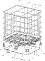
使い捨て及び再使用用容器として使用される液体及びばら荷のための図1及び2による輸送及び貯蔵用容器6は、主要部品として、キャップ9で閉鎖可能な上底部10における注入パイプ8と、採取及び洗浄コック13を接続するための下底部12の領域内にある排出パイプ11とを備えている合成物質から成る交換可能な角形の内部容器7を、また格子ケージ14として形成された、金属から成る交差する水平及び垂直な格子棒15,16から成る外部ジャケットを、並びに欧州標準仕様の長さ及び幅寸法を有する金属から成るパレット状の台座17を備える。
The transport and
処理のためにフォークリフト、入出庫ユニット及びそのような輸送手段によって設置される輸送及び貯蔵用容器6のパレット状の台座17は、内部容器7を支持するための金属板から成る底部18を備えている。台座17の底部18は、金属板から成る4つの角足部19〜22及び後の中央足部23、内部容器7の採取及び洗浄コック13の下に配設されている底部18から形成された前方の中央足部24、並びに2つの横の中央足部25,26上に載っている。台座17の角及び中央の足部19〜26は、金属から成る足部フレーム27上に固定されている。
The pallet-
図3及び4による輸送及び貯蔵用容器6の台座17の角足部19は、台座17の平坦なバスタブ状の底部18の外縁部30及び格子ケージ14として形成された外部ジャケットの下部フレーム31を載置するための上の支持縁部29並びに下の接地縁部32を有する湾曲したシェル用金属板28によって構成され、この接地縁部で、角足部19は、台座17の足部フレーム27上に立っている。複数の輸送用容器6を積み重ねる場合、それぞれ積み上げられる輸送用容器は、角足部19〜22の下の接地縁部32でそれぞれ重ねられる輸送用容器の格子ケージ14の上部フレーム33上に支持される。
The
角足部19のシェル用金属板28の上の支持縁部29の2つの外側の部分29a,29bには、2つの上の中空のリベット軸34,34が、シェル用金属板28の下の接地縁部32の2つの外側の部分32a,32bには、2つの下の中空のリベット軸35,35が配設されている。上下のリベット軸34,35は、上もしくは下に向かって角足部19から突出する。角足部19のシェル用金属板28における下のリベット軸35,35は、上のリベット軸34,34に対して平行に内側に向かって、また垂直方向に角足部19の上の支持縁部29と下の設置縁部32の垂直間隔36に応じて互いにずらされて配設されている。
Two upper
角足部19のそれぞれ1つの上下のリベット軸34,35は、チューブ部材37の2つの曲がった端部によって構成されており、その際、チューブ部材37,37は、角足部19のシェル用金属板28の外縁部28a,28bから内側に向かって曲げられた傾斜した2つの外側の脚部38,39に形成、特にロール成形されている。
Each of the upper and lower
角足部19の変化させた実施形の場合、それぞれ1つの上下のリベット軸34,35を有するチューブ部材37は、シェル用金属板28に溶接されている。
In the case of the modified embodiment of the
角足部19の外側の脚部38,39の内側に転造されたそれぞれ1つの上下のリベット軸34,35を有するチューブ部材37によって、角足部19の脚部38,39は補強される。この補強によって、輸送及び貯蔵用容器6の台座17を運び入れる場合及び輸送車両、特にフォークリフトのグリップアームによって容器をずらす場合の角足部19の損傷が回避される。
The
輸送及び貯蔵用容器6の台座17と格子ケージ14を組み立てる場合、角足部19〜22の上のリベット軸34は、底部18の外縁部30における及びリベット孔41の領域内が平らにされた格子ケージ14の下部フレーム31における相応の合同のリベット孔40,41に差し込まれ、相応のリベット孔42を備えているこれらリベット孔の領域内が平らにされた台座17の足部フレーム27は、角足部19〜22の下のリベット軸35に取り付けられる。引き続き、角足部19〜22のリベット孔41の領域内が平らにされた格子ケージ14の下部フレーム31から突出する上のリベット軸34の自由端34aと、リベット孔42の領域内が平らにされた台座17の足部フレーム27から突出する下のリベット軸35の自由端35aとは、リベット工具で閉鎖ヘッド43と成るように変形され、従って、角足部19〜22は、一方では底部18及び格子ケージ14の下部フレーム31と、他方では足部フレーム27とリベット止めされる。
When assembling the
図5による角足部19の別の実施形の場合、上のリベット軸34,34は、シェル用金属板28の2つの外縁部28a,28bに、また下のリベット軸35,35は、シェル用金属板28の縁部28a,28bから内側に向かって曲げられた2つの外側の脚部44,45に転造されている。
In the case of another embodiment of the
更に、図5による角足部19の場合、上下のリベット軸34,35をシェル用金属板28及びその脚部44,45に溶接する可能性がある。
Further, in the case of the
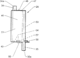
その内の一方25が図6〜8に図示されている横の中央足部25,26と台座17の後の中央足部23は、支持面48を備える上の壁47と、接地面50を有する下の壁49と、ボックス46の2つの側面51,52に転造されたそれぞれ1つの下のリベット軸35を有する2つのチューブ部材53,53と、上のボックス壁47の支持面48に転造された2つの上のリベット軸34,34とを有する開放したボックス46の形を備えている。中央足部23,25,26は、その自由端34a,35aが閉鎖ヘッド43と成るように変形可能である上下のリベット軸34,35によって角足部19〜22と同じ方式で底部18の外縁部30及びこの外縁部上に載置されている格子ケージ14の下部フレーム31並びに足部フレーム27とリベット止めされる。
The lateral
2つの横の中央足部25,26の下の壁49は、内側に、台座底部18の中心の補強ウェブ55の下に向かって曲がった2つの外側の端部56のそれぞれ1つのための支持面54を備えており、中央足部25,26の下のボックス壁49から、台座底部18の補強ウェブ55の端部56と中央足部をリベット止めするための内側に向かって整向された2つの中空のリベット軸57,58が形成されている(図2,6〜8)。
The
リベット止めによる代わりに、横の中央足部25,26は、貫通接合として公知の接合方法によって台座底部18の補強ウェブ55の端部56と互いに結合することができる。更に、リベット軸34,35,57,58を個別のスリーブとして横の中央足部25,26に溶接するという可能性がある。
Instead of being riveted, the lateral
図9は、セグメント化された一体的なボックス形状46を有する台座17の横の中央足部25を示す。
FIG. 9 shows the
図10に図示された台座17の横の中央足部25は、支持面48を備える上の壁47と、接地面50を有する下の壁49と、ボックス46の2つの傾斜した側壁51,52に転造されたそれぞれ1つの上下のリベット軸34,35を構成する2つの曲がった端部を有する2つのチューブ部材53,53とを有する開放したボックス46の形を備えている。横の中央足部25の下の壁49は、台座底部18の中心の補強ウェブ55の2つの端部56の一方のための内側の支持面54と、並びに補強ウェブ55の一方の端部56と中央足部をリベット止めするための2つのリベット軸57,58とを備える。
The
図11によれば、底部と一体的に製造された前方の中央足部24の両側で台座底部18と格子ケージ14の下部フレーム14を結合するために、下部フレーム31から形成されたそれぞれ2つの中空のリベット軸59,59が使用され、これらのリベット軸は、底部18の外縁部30におけるリベット孔40に差し込まれ、これらリベット軸の自由端59aは、リベット工具によって底縁部30の下側60に対して閉鎖ヘッド43と成るように変形されている。
Referring to FIG. 11 , two each formed from the
格子ケージ14の下部フレーム31から形成されたリベット軸59の代わりに、台座底部18と格子ケージの下部フレームをリベット止めするために、個別の中空リベットが使用されてもよい。
Instead of a
図2によれば、台座17の前方の中央足部24は、セットヘッドを有する中空リベット61によって足部フレーム27上に固定されている。
According to FIG. 2 , the
図12は、その台座17が木製スキッド62を装備されている液体のための輸送及び貯蔵用容器6を示す。
FIG. 12 shows a transport and
図13に図示された台座17の横の中央足部25を台座17の木製スキッド62に固定するため、中央足部25の2つの下のリベット軸35は、木製スキッド62の相応の垂直孔63に差し込まれる。引き続き、それぞれ1つのワッシャ64が、木製スキッド62から突出するリベット軸35の自由端35aに挿入することができ、これにより、リベット軸35の端部35aが、リベット工具によって閉鎖ヘッド43と成るように変形され、これらの閉鎖ヘッドは、垂直孔63の凹部65内に入っている。
In order to fix the lateral
同じ方式で、第2の横の中央足部26と後の中央足部23と4つの角足部19〜22が台座17の木製スキッド62に取り付けられる。前方の中央足部24を台座17の中央の木製スキッド62上に固定するため、セットヘッドを有する中空リベットが使用される。
In the same manner, the second
6 輸送及び貯蔵用容器
7 内部容器
8 注入パイプ
9 キャップ
10 上底部
11 排出パイプ
12 下底部
13 採取及び洗浄コック
14 格子ケージ
15,16 格子棒
17 台座
18 底部
19〜22 角足部
23 後の中央足部
24 中央足部
25,26 横の中央足部
27 足部フレーム
28 シェル用金属板
28a,28b 外縁部
29 支持縁部
29a,29b 外側の部分
30 外縁部
31 下部フレーム
32 接地縁部
32a,32b 外側の部分
33 上部フレーム
34 上のリベット軸
34a 自由端
35 下のリベット軸
35a 自由端
36 垂直間隔
37 チューブ部材
38,39 外側の脚部
40,41 リベット孔
42 リベット孔
43 閉鎖ヘッド
44,45 外側の脚部
46 ボックス
47 上の壁
48 支持面
49 下の壁
50 接地面
51,52 側壁
53 チューブ部材
54 支持面
55 補強ウェブ
56 端部
57,58 リベット軸
59 リベット軸
59a 自由端
60 下側
61 中空リベット
62 木製スキッド
63 垂直孔
64 ワッシャ
65 凹部
6 Transport and storage container 7 Inner container 8 Injection pipe 9
59a
Claims (9)
角足部(19〜22)及び中央足部(23,25,26)に一体的に形成された又は別個に溶接された上及び/又は下のリベット軸(34,35)が設けられており、これらの軸が、角足部(19〜22)もしくは中央足部(23,25,26)から上及び下に向かって突出し、これらの軸の自由端(34a,35a)が、格子ケージ(14)の下部フレーム(31)又は金属板ジャケットの下縁部及び台座(17)の金属板底部(18)の外縁部(30)を角足部(19〜22)及び中央足部(23,25,26)に固定するため及び角足部(19〜22)及び中央足部(23,25,26)を台座(17)の足部フレーム(27)に固定するために、それぞれ1つの閉鎖ヘッド(43)と成るように変形可能であることを特徴とする中空リベット継手。 An inner container made of a synthetic material having a pallet-shaped pedestal (17) and a discharge pipe (11) for connecting a closable injection pipe (8) and a sampling fitting (13) existing on the pedestal (7) and a lattice cage (14) or an outer jacket formed as a metal plate jacket , the pedestal (17) supporting the inner container (7) at the bottom (18) and the metal plate With horns and central feet (19-22; 23-26) made of metal and attached to a foot frame (27) made of metal or a skid (62) made of metal, synthetic material or wood is and, set the bottom (18) and outer jacket of the inner container (7) is fixed, transport and storage container for liquids and bulk of the base (17) of these legs (6) In the hollow rivet joint for Teru,
Upper and / or lower rivet shafts (34, 35) are provided integrally or separately welded to the corner feet (19-22) and the central feet (23, 25, 26) These shafts protrude upward and downward from the corner feet (19-22) or the central feet (23, 25, 26), and the free ends (34a, 35a) of these shafts are connected to the lattice cage ( 14) the lower frame (31) or the lower edge of the metal plate jacket and the outer edge (30) of the metal plate bottom (18) of the pedestal (17), the square foot (19-22) and the central foot (23, 25, 26) and one closure each for securing the square foot (19-22) and the central foot (23, 25, 26) to the foot frame (27) of the pedestal (17). hollow, characterized in that is deformable in such a way that the head (43) Bet the joint.
Applications Claiming Priority (1)
| Application Number | Priority Date | Filing Date | Title |
|---|---|---|---|
| DE202004003020U DE202004003020U1 (en) | 2004-02-27 | 2004-02-27 | Hollow rivet connection for components made of metal, plastic or wood, in particular for the assembly of transport and storage containers for liquids |
Publications (2)
| Publication Number | Publication Date |
|---|---|
| JP2005246481A JP2005246481A (en) | 2005-09-15 |
| JP4101244B2 true JP4101244B2 (en) | 2008-06-18 |
Family
ID=32240902
Family Applications (1)
| Application Number | Title | Priority Date | Filing Date |
|---|---|---|---|
| JP2005049859A Expired - Fee Related JP4101244B2 (en) | 2004-02-27 | 2005-02-25 | Hollow rivet joint for assembling transport and storage containers for liquids and bulk loads |
Country Status (15)
| Country | Link |
|---|---|
| US (1) | US7866501B2 (en) |
| EP (1) | EP1568896B1 (en) |
| JP (1) | JP4101244B2 (en) |
| CN (1) | CN100534873C (en) |
| AR (1) | AR047979A1 (en) |
| AU (1) | AU2005200863B2 (en) |
| BR (1) | BRPI0500564A (en) |
| DE (2) | DE202004003020U1 (en) |
| ES (1) | ES2535432T3 (en) |
| MX (1) | MXPA05002155A (en) |
| MY (1) | MY140586A (en) |
| NO (1) | NO337431B1 (en) |
| PL (1) | PL1568896T3 (en) |
| RU (1) | RU2288379C1 (en) |
| ZA (1) | ZA200501451B (en) |
Families Citing this family (16)
| Publication number | Priority date | Publication date | Assignee | Title |
|---|---|---|---|---|
| DE202004014102U1 (en) * | 2004-09-08 | 2004-11-04 | Mauser-Werke Gmbh & Co. Kg | pallet container |
| TWI290397B (en) * | 2005-11-14 | 2007-11-21 | Hon Hai Prec Ind Co Ltd | Method of assembling an electrical connector |
| ES2340625T3 (en) * | 2007-04-18 | 2010-06-07 | Daviplast - Servicos De Consultoria, Sociedade Unipessoal Lda. | PALLET CONTAINER. |
| DE102009040102B4 (en) * | 2009-09-04 | 2011-07-07 | Miele & Cie. KG, 33332 | Rivet and basket insert |
| DE102010040270A1 (en) * | 2010-09-06 | 2012-03-08 | Protechna S.A. | Transport and storage container for liquids |
| DE102010048609B4 (en) * | 2010-10-15 | 2013-06-27 | Ekkehard Schneider | Container arrangement with stiffening element |
| DE102011007583B4 (en) * | 2011-04-18 | 2015-07-09 | Protechna S.A. | Pallet-type base for transport and storage containers for liquids |
| DE102011007587A1 (en) * | 2011-04-18 | 2012-10-18 | Protechna S.A. | Pallet-type base for transport and storage containers for liquids |
| CN102228880A (en) * | 2011-06-18 | 2011-11-02 | 津伦(天津)精密机械股份有限公司 | Workpiece holding basket capable of overturning and reversely loading and unloading workpieces |
| WO2016040300A1 (en) | 2014-09-08 | 2016-03-17 | Green Ox Pallet Technology, Llc | Lightweight and rigid pallet |
| US9452881B2 (en) * | 2014-11-17 | 2016-09-27 | Mobile Shelter Systems As | Cargo locker with doors |
| WO2017118599A1 (en) | 2016-01-07 | 2017-07-13 | Mauser-Werke Gmbh | Pallet container |
| AU2019231331A1 (en) * | 2018-03-09 | 2020-09-24 | Incitias Pty Ltd | Containment system for storing and transporting bulk liquid |
| DE102018113115B3 (en) * | 2018-06-01 | 2019-09-26 | Protechna S.A. | Transport and storage container for liquids |
| WO2022180128A1 (en) * | 2021-02-24 | 2022-09-01 | Illucens Gmbh | Handling device and method used in insect breeding |
| DE102021121667A1 (en) | 2021-08-20 | 2023-02-23 | Protechna S.A. | Pallet-like underframe for a transport and storage container and assembly kit for producing such an underframe and transport and storage container with such an underframe |
Family Cites Families (13)
| Publication number | Priority date | Publication date | Assignee | Title |
|---|---|---|---|---|
| US3952913A (en) * | 1974-11-18 | 1976-04-27 | Continental Can Company, Inc. | Tab anti-rotation and hold down device |
| DE3639870A1 (en) * | 1986-11-21 | 1988-06-01 | Daimler Benz Ag | SECURITY DEVICE FOR DETECTING THE UNAUTHORIZED OPENING OF A HOUSING |
| DD260737A1 (en) * | 1987-05-21 | 1988-10-05 | Goerlitz Waggonbau Veb | METHOD FOR CONNECTING A VARIETY OF NATURAL BUILDING COMPONENTS |
| FR2619169B1 (en) * | 1987-08-07 | 1989-10-06 | Tubauto | METHOD AND DEVICE FOR THE QUICK CONNECTION OF TWO PARTS HAVING, IN GENERAL, PLANAR OVERLAY AREAS |
| DE4206945C1 (en) * | 1991-03-15 | 1993-03-11 | Schuetz-Werke Gmbh & Co. Kg, 5418 Selters, De | |
| US5285873A (en) * | 1992-02-19 | 1994-02-15 | Ray Arbesman | Disk brake friction assembly |
| WO1998012124A1 (en) * | 1996-09-19 | 1998-03-26 | Roth Werke Gmbh | Pallet container |
| DE10027422A1 (en) * | 2000-06-02 | 2002-06-06 | Ina Schaeffler Kg | rivet |
| DK1343703T3 (en) * | 2000-11-23 | 2007-10-29 | Mauser Werke Gmbh | pallet Container |
| DE20020648U1 (en) * | 2000-12-06 | 2001-02-15 | Protechna Sa | Pallet-like base for transport and storage containers for liquids |
| DE20217856U1 (en) * | 2002-11-19 | 2003-02-13 | Protechna Sa | Pallet-like base, especially for transport and storage containers for liquids |
| DE10301517B3 (en) * | 2003-01-17 | 2004-03-11 | Protechna S.A. | Transport and storage container for liquid has vertical grid rods of grid mantle enclosing inner plastics container welded to upper edge profile supporting stacked container |
| DE20316883U1 (en) * | 2003-10-31 | 2004-03-11 | Protechna S.A. | Pallet-type base for transport and storage containers for liquids |
-
2004
- 2004-02-27 DE DE202004003020U patent/DE202004003020U1/en not_active Expired - Lifetime
- 2004-07-23 DE DE102004035857A patent/DE102004035857B4/en not_active Expired - Fee Related
-
2005
- 2005-02-17 ZA ZA200501451A patent/ZA200501451B/en unknown
- 2005-02-18 US US11/061,851 patent/US7866501B2/en not_active Expired - Fee Related
- 2005-02-18 PL PL05003552T patent/PL1568896T3/en unknown
- 2005-02-18 ES ES05003552.6T patent/ES2535432T3/en active Active
- 2005-02-18 EP EP05003552.6A patent/EP1568896B1/en not_active Not-in-force
- 2005-02-24 MX MXPA05002155A patent/MXPA05002155A/en active IP Right Grant
- 2005-02-25 RU RU2005105410/11A patent/RU2288379C1/en not_active IP Right Cessation
- 2005-02-25 JP JP2005049859A patent/JP4101244B2/en not_active Expired - Fee Related
- 2005-02-25 BR BR0500564-7A patent/BRPI0500564A/en not_active Application Discontinuation
- 2005-02-25 CN CNB2005100528812A patent/CN100534873C/en not_active Expired - Fee Related
- 2005-02-25 NO NO20051026A patent/NO337431B1/en not_active IP Right Cessation
- 2005-02-25 AR ARP050100703A patent/AR047979A1/en not_active Application Discontinuation
- 2005-02-25 MY MYPI20050776A patent/MY140586A/en unknown
- 2005-02-25 AU AU2005200863A patent/AU2005200863B2/en not_active Ceased
Also Published As
| Publication number | Publication date |
|---|---|
| CN100534873C (en) | 2009-09-02 |
| EP1568896B1 (en) | 2015-01-28 |
| DE102004035857B4 (en) | 2006-01-19 |
| AU2005200863A1 (en) | 2005-09-15 |
| DE202004003020U1 (en) | 2004-04-29 |
| RU2288379C1 (en) | 2006-11-27 |
| ZA200501451B (en) | 2005-09-05 |
| AR047979A1 (en) | 2006-03-15 |
| RU2005105410A (en) | 2006-08-10 |
| NO337431B1 (en) | 2016-04-11 |
| BRPI0500564A (en) | 2005-10-18 |
| CN1664387A (en) | 2005-09-07 |
| NO20051026D0 (en) | 2005-02-25 |
| PL1568896T3 (en) | 2015-07-31 |
| ES2535432T3 (en) | 2015-05-11 |
| AU2005200863B2 (en) | 2008-09-25 |
| NO20051026L (en) | 2005-08-29 |
| EP1568896A3 (en) | 2007-03-28 |
| MY140586A (en) | 2009-12-31 |
| JP2005246481A (en) | 2005-09-15 |
| MXPA05002155A (en) | 2005-08-31 |
| DE102004035857A1 (en) | 2005-09-22 |
| US20050196252A1 (en) | 2005-09-08 |
| US7866501B2 (en) | 2011-01-11 |
| EP1568896A2 (en) | 2005-08-31 |
Similar Documents
| Publication | Publication Date | Title |
|---|---|---|
| JP4101244B2 (en) | Hollow rivet joint for assembling transport and storage containers for liquids and bulk loads | |
| KR100518772B1 (en) | A Stackable Knock Down Box | |
| EP1819599B1 (en) | Pallet for storing and transporting goods | |
| US5704477A (en) | Pallet-type storage/transport container | |
| RU2525783C2 (en) | Carrying frame in form of pallet for containers for transportation and storage of liquids | |
| US5058747A (en) | Transport/storage container with wooden pallet feet | |
| JP4423279B2 (en) | Transport and storage containers for liquids | |
| JP2007508211A (en) | palette | |
| JP2007508211A5 (en) | ||
| KR20110128978A (en) | Pallet | |
| JP4012555B2 (en) | Stackable shelf structure | |
| KR101115606B1 (en) | Structure for reinforcing strength in pallet | |
| KR101613010B1 (en) | Steel box | |
| KR101810977B1 (en) | Assembly type steel pallet | |
| CA2654131A1 (en) | Pallet for storing and transporting goods | |
| KR101457902B1 (en) | Packing case for export and the fabrication method | |
| KR101693331B1 (en) | Multipurpose Steel Pallets | |
| KR101610910B1 (en) | Multipurpose steel pallets | |
| KR101612531B1 (en) | Steel pallet | |
| JP7174075B2 (en) | Liquid transport and storage containers | |
| JP6800674B2 (en) | How to make a container | |
| KR101250298B1 (en) | Steel pallet for loading goods | |
| JP7032703B2 (en) | Structure of base for prefabricated container | |
| JPH0516106Y2 (en) | ||
| JP2008081127A (en) | Knockdown container |
Legal Events
| Date | Code | Title | Description |
|---|---|---|---|
| A977 | Report on retrieval |
Free format text: JAPANESE INTERMEDIATE CODE: A971007 Effective date: 20070305 |
|
| A131 | Notification of reasons for refusal |
Free format text: JAPANESE INTERMEDIATE CODE: A131 Effective date: 20070327 |
|
| A521 | Written amendment |
Free format text: JAPANESE INTERMEDIATE CODE: A523 Effective date: 20070607 |
|
| A131 | Notification of reasons for refusal |
Free format text: JAPANESE INTERMEDIATE CODE: A131 Effective date: 20070731 |
|
| A601 | Written request for extension of time |
Free format text: JAPANESE INTERMEDIATE CODE: A601 Effective date: 20071012 |
|
| A602 | Written permission of extension of time |
Free format text: JAPANESE INTERMEDIATE CODE: A602 Effective date: 20071017 |
|
| A601 | Written request for extension of time |
Free format text: JAPANESE INTERMEDIATE CODE: A601 Effective date: 20071119 |
|
| A602 | Written permission of extension of time |
Free format text: JAPANESE INTERMEDIATE CODE: A602 Effective date: 20071122 |
|
| TRDD | Decision of grant or rejection written | ||
| A01 | Written decision to grant a patent or to grant a registration (utility model) |
Free format text: JAPANESE INTERMEDIATE CODE: A01 Effective date: 20080304 |
|
| A61 | First payment of annual fees (during grant procedure) |
Free format text: JAPANESE INTERMEDIATE CODE: A61 Effective date: 20080318 |
|
| FPAY | Renewal fee payment (event date is renewal date of database) |
Free format text: PAYMENT UNTIL: 20110328 Year of fee payment: 3 |
|
| R150 | Certificate of patent or registration of utility model |
Free format text: JAPANESE INTERMEDIATE CODE: R150 |
|
| FPAY | Renewal fee payment (event date is renewal date of database) |
Free format text: PAYMENT UNTIL: 20110328 Year of fee payment: 3 |
|
| FPAY | Renewal fee payment (event date is renewal date of database) |
Free format text: PAYMENT UNTIL: 20120328 Year of fee payment: 4 |
|
| FPAY | Renewal fee payment (event date is renewal date of database) |
Free format text: PAYMENT UNTIL: 20130328 Year of fee payment: 5 |
|
| FPAY | Renewal fee payment (event date is renewal date of database) |
Free format text: PAYMENT UNTIL: 20140328 Year of fee payment: 6 |
|
| R250 | Receipt of annual fees |
Free format text: JAPANESE INTERMEDIATE CODE: R250 |
|
| R250 | Receipt of annual fees |
Free format text: JAPANESE INTERMEDIATE CODE: R250 |
|
| R250 | Receipt of annual fees |
Free format text: JAPANESE INTERMEDIATE CODE: R250 |
|
| LAPS | Cancellation because of no payment of annual fees |