EP1568852B1 - Hydraulisches Spielausgleichselement und dessen Baumethode - Google Patents
Hydraulisches Spielausgleichselement und dessen Baumethode Download PDFInfo
- Publication number
- EP1568852B1 EP1568852B1 EP05250855A EP05250855A EP1568852B1 EP 1568852 B1 EP1568852 B1 EP 1568852B1 EP 05250855 A EP05250855 A EP 05250855A EP 05250855 A EP05250855 A EP 05250855A EP 1568852 B1 EP1568852 B1 EP 1568852B1
- Authority
- EP
- European Patent Office
- Prior art keywords
- check valve
- plunger
- bore
- valve assembly
- assembly
- Prior art date
- Legal status (The legal status is an assumption and is not a legal conclusion. Google has not performed a legal analysis and makes no representation as to the accuracy of the status listed.)
- Expired - Lifetime
Links
- 238000000034 method Methods 0.000 title claims description 19
- 239000012530 fluid Substances 0.000 claims description 32
- 238000004891 communication Methods 0.000 claims description 14
- 230000000712 assembly Effects 0.000 claims description 12
- 238000000429 assembly Methods 0.000 claims description 12
- 230000000903 blocking effect Effects 0.000 claims description 4
- 238000002485 combustion reaction Methods 0.000 claims description 4
- 238000013461 design Methods 0.000 description 5
- 238000012360 testing method Methods 0.000 description 5
- 238000004519 manufacturing process Methods 0.000 description 4
- 230000006835 compression Effects 0.000 description 3
- 238000007906 compression Methods 0.000 description 3
- 230000004075 alteration Effects 0.000 description 2
- 230000014759 maintenance of location Effects 0.000 description 2
- 239000000463 material Substances 0.000 description 2
- 230000013011 mating Effects 0.000 description 2
- 238000012986 modification Methods 0.000 description 2
- 230000004048 modification Effects 0.000 description 2
- 230000000717 retained effect Effects 0.000 description 2
- 238000013459 approach Methods 0.000 description 1
- 230000004323 axial length Effects 0.000 description 1
- 238000010276 construction Methods 0.000 description 1
- 238000002788 crimping Methods 0.000 description 1
- 238000003780 insertion Methods 0.000 description 1
- 230000037431 insertion Effects 0.000 description 1
- 238000009434 installation Methods 0.000 description 1
- 238000003754 machining Methods 0.000 description 1
- 238000011056 performance test Methods 0.000 description 1
- 230000005477 standard model Effects 0.000 description 1
Images

Classifications
-
- F—MECHANICAL ENGINEERING; LIGHTING; HEATING; WEAPONS; BLASTING
- F01—MACHINES OR ENGINES IN GENERAL; ENGINE PLANTS IN GENERAL; STEAM ENGINES
- F01L—CYCLICALLY OPERATING VALVES FOR MACHINES OR ENGINES
- F01L1/00—Valve-gear or valve arrangements, e.g. lift-valve gear
- F01L1/20—Adjusting or compensating clearance
- F01L1/22—Adjusting or compensating clearance automatically, e.g. mechanically
- F01L1/24—Adjusting or compensating clearance automatically, e.g. mechanically by fluid means, e.g. hydraulically
- F01L1/2422—Adjusting or compensating clearance automatically, e.g. mechanically by fluid means, e.g. hydraulically by means or a hydraulic adjusting device located between the push rod and rocker arm
-
- F—MECHANICAL ENGINEERING; LIGHTING; HEATING; WEAPONS; BLASTING
- F01—MACHINES OR ENGINES IN GENERAL; ENGINE PLANTS IN GENERAL; STEAM ENGINES
- F01L—CYCLICALLY OPERATING VALVES FOR MACHINES OR ENGINES
- F01L1/00—Valve-gear or valve arrangements, e.g. lift-valve gear
- F01L1/20—Adjusting or compensating clearance
- F01L1/22—Adjusting or compensating clearance automatically, e.g. mechanically
- F01L1/24—Adjusting or compensating clearance automatically, e.g. mechanically by fluid means, e.g. hydraulically
- F01L1/2405—Adjusting or compensating clearance automatically, e.g. mechanically by fluid means, e.g. hydraulically by means of a hydraulic adjusting device located between the cylinder head and rocker arm
-
- Y—GENERAL TAGGING OF NEW TECHNOLOGICAL DEVELOPMENTS; GENERAL TAGGING OF CROSS-SECTIONAL TECHNOLOGIES SPANNING OVER SEVERAL SECTIONS OF THE IPC; TECHNICAL SUBJECTS COVERED BY FORMER USPC CROSS-REFERENCE ART COLLECTIONS [XRACs] AND DIGESTS
- Y10—TECHNICAL SUBJECTS COVERED BY FORMER USPC
- Y10T—TECHNICAL SUBJECTS COVERED BY FORMER US CLASSIFICATION
- Y10T29/00—Metal working
- Y10T29/49—Method of mechanical manufacture
- Y10T29/49229—Prime mover or fluid pump making
- Y10T29/49247—Valve lifter making
-
- Y—GENERAL TAGGING OF NEW TECHNOLOGICAL DEVELOPMENTS; GENERAL TAGGING OF CROSS-SECTIONAL TECHNOLOGIES SPANNING OVER SEVERAL SECTIONS OF THE IPC; TECHNICAL SUBJECTS COVERED BY FORMER USPC CROSS-REFERENCE ART COLLECTIONS [XRACs] AND DIGESTS
- Y10—TECHNICAL SUBJECTS COVERED BY FORMER USPC
- Y10T—TECHNICAL SUBJECTS COVERED BY FORMER US CLASSIFICATION
- Y10T74/00—Machine element or mechanism
- Y10T74/21—Elements
- Y10T74/2101—Cams
- Y10T74/2107—Follower
Definitions
- the present invention relates to hydraulic lash adjusters for internal combustion engines, and more particularly, to an improved check valve assembly for use in such lash adjusters, and to an improved method of assembling such lash adjusters.
- a conventional hydraulic lash adjuster of the type to which the present invention relates
- an outer body which is typically disposed within a mating bore in the engine cylinder head, and disposed within the body is an output plunger assembly engaging a rocker arm.
- the output plunger assembly may be of either a one-piece or a two-piece construction, and typically, includes a ball plunger element which engages a socket formed in an "underside" surface of the rocker arm.
- a blind bore formed within the body cooperates with the plunger assembly to define a high pressure chamber, as is well known to those skilled in the art.
- HLA's which are sold commercially are of the "conventional leakdown” type, in which the radial clearance space between the outer diameter of the plunger and the inner diameter of the body bore forms a leakdown path.
- This leakdown path (or clearance) permits communication of fluid from the high pressure chamber, through the leakdown clearance, and into the reservoir (or "low pressure” chamber) of the HLA whenever an axial force is transmitted from the rocker arm to the ball plunger.
- HLA the "leakdown" performance of the HLA, i.e., the leakdown flow and resulting plunger assembly travel, as a function of time, for a given force applied to the plunger assembly.
- the HLA must provide a leakdown performance which is within a predetermined, specified tolerance range, in order for the HLA to be acceptable for assembly into the engine cylinder head, and in order for the engine valve gear train to operate in a manner which is satisfactory.
- a check valve assembly disposed between the high pressure chamber and the low pressure (reservoir) chamber, and operable to control (either to block or to permit) fluid communication between those two chambers, in response to the instantaneous pressure differential between the chambers. Therefore, in the typical HLA, the lower end of the plunger assembly defines a check valve seat, and prior to insertion of the plunger assembly into the HLA body, the check valve assembly (typically consisting of a check ball, a spring, and some sort of retainer) is assembled to the lower end of the plunger assembly.
- check valve assembly performance in terms of the rate of fluid flow from the low pressure chamber into the high pressure chamber (or vice versa), in response to a particular pressure differential between the chambers.
- the HLA must provide a check valve assembly performance which is within a predetermined, specified tolerance range, in order for the HLA to be acceptable for assembly into the engine cylinder head, and in order for the engine valve gear train to operate in manner which is satisfactory.
- HLA manufacturer normally produces several different, standard HLA models, each in relatively large volume, it is quite common for an engine manufacturer to request or need an HLA which is nearly identical to one of the standard models, but differs in respect to perhaps only one of the performance criteria, such as the leakdown performance, or the check valve performance, or the plunger travel.
- HLA manufacturer has the opportunity to make and sell such a non-standard HLA, it is then necessary for the HLA manufacturer to design (and provide tooling for) the non-standard part of the HLA, and design and test what then is effectively a whole new HLA design, and a different part number, even though the resulting HLA may have much commonality with an existing model.
- This approach to designing and manufacturing new HLA models adds substantially to the overall cost of manufacture of the HLA and the lead time to produce the required, non-standard HLA.
- an improved hydraulic lash adjuster for an internal combustion engine comprises a body defining a bore therein, a plunger slidingly received within the bore and defining a fluid chamber, the plunger and the bore cooperating to define a pressure chamber, and biasing means normally urging the plunger outward of the bore.
- the body and the plunger cooperate to define a leakdown clearance providing fluid communication between the pressure chamber and the fluid chamber.
- a check valve assembly is operably associated with the plunger for permitting or blocking fluid communication between the fluid chamber and the pressure chamber in response to changes in the pressure difference between the chambers.
- the check valve assembly has a predetermined relationship of permitted fluid communication versus pressure difference.
- the improved hydraulic lash adjuster is characterized by the check valve assembly comprising a member, separate from the plunger, the member defining a valve seat.
- the check valve assembly further comprises a valve member, a spring disposed to bias the valve member toward its normal position, and a retaining member to retain the valve member.
- the check valve assembly is capable of being assembled and tested for compliance with the predetermined relationship of permitted fluid communication versus pressure difference, prior to installation of the check valve assembly within the plunger.
- an improved method of assembling a hydraulic lash adjuster comprising a body defining a bore therein, a plunger slidingly received within the bore, and defining a fluid chamber.
- the plunger and the bore cooperate to define a pressure chamber, and biasing means normally urges the plunger outward of the bore.
- the body and the plunger cooperate to define a leakdown clearance providing fluid communication between the pressure chamber and the fluid chamber.
- a check valve assembly is operably associated with the plunger for permitting or blocking fluid communication between the fluid chamber and the pressure chamber in response to changes in pressure difference between the chambers.
- the improved method of assembly is characterized by (a) providing the body defining the bore; (b) providing a plurality of check valve assemblies, including a first check valve assembly and a second check valve assembly, the first and second check valve assemblies having substantially the same exterior configuration, but differing from each other in some performance criteria; (c) providing a plurality of plungers including a first plunger having a first characteristic and a second plunger having a second characteristic; (d) selecting one of the first and second check valve assemblies; (e) selecting one of the first and second plungers and installing therein the selected check valve assembly; and (f) inserting within the bore of the body the selected plunger and check valve assembly combination.
- FIG. 1 is an axial cross-section of one particular embodiment of hydraulic lash adjuster, made in accordance with the present invention.
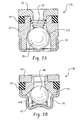
- FIG. 2A is an enlarged, axial cross-section of a check valve cartridge of the normally biased-open type, which comprises one aspect of the present invention.
- FIG. 2B is an enlarged, axial cross-section of a check valve cartridge of the normally biased-closed type, and on the same scale as FIG. 1 .
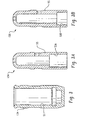
- FIG. 3 is an axial cross-section of a hydraulic lash adjuster body, on a substantially smaller scale than FIGS. 2A and 2B .
- FIGS. 3A and 3B are axial cross-sections of lash adjuster plungers useable with the body of FIG. 3 , and on the same scale as FIG. 3 .
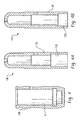
- FIG. 4 is an axial cross-section of a hydraulic lash adjuster body which is different than that shown in FIG. 3 , but on the same scale.
- FIGS. 4A and 4B are axial cross-sections of plungers useable with the body of FIG. 4 , and on the same scale as FIG. 4 .
- FIG. 1 is an axial cross-section of one particular embodiment of HLA, by way of example only, made in accordance with the present invention. Therefore, FIG. 1 shows an hydraulic lash adjuster, generally designated 11, which may be of the general type illustrated and described in U.S. Patent No. 5,855,191 , assigned to the assignee of the present invention and incorporated herein by reference.
- an hydraulic lash adjuster generally designated 11 which may be of the general type illustrated and described in U.S. Patent No. 5,855,191 , assigned to the assignee of the present invention and incorporated herein by reference.
- the present invention in each of its aspects, is not limited to the particular type of or configuration of HLA shown in FIG. 1 , as will be explained in greater detail subsequently.
- the HLA 11 may be of a general type and configuration well known to those skilled in the art (except where noted otherwise hereinafter), and will be described only briefly at this point.
- the HLA 11 includes a body 13 which, as noted previously, would typically be disposed within a mating bore in the engine cylinder head (not shown herein).
- a plunger 15 including a check valve assembly, generally designated 17, with the combination of the plunger 15 and the check valve assembly 17 being biased in an "outward" direction (upward in FIG. 1 ), relative to the body 13, by means of a plunger spring 19.
- a fluid chamber 21 Disposed within the plunger 15 is a fluid chamber 21 (also referred to hereinafter as a “reservoir” or a “low pressure chamber”).
- the body 13 and the lower end of the plunger 15 cooperate to define a high pressure chamber 23 (also referred to hereinafter, and in the appended claims, as simply the "pressure chamber”).
- the function of the check valve assembly 17 is either to permit fluid communication, or to block fluid communication, between the low pressure chamber 21 and the high pressure chamber 23, in response to the pressure differential between the chambers 21 and 23.
- a cap member 25 Disposed about the upper end of the body 13 is a cap member 25, the function of which is to retain the plunger 15, and limit outward movement thereof relative to the body 13. It should be understood that the particular configuration of the cap member 25, or even the presence of any cap member, is not an essential feature of the invention, and all that is essential to the invention (as is essential to any HLA) is that there be provided some suitable means for retaining the plunger 15 within the body 13.
- the check valve assembly 17 shown in FIG. 1 comprises a check valve cartridge.
- check valve cartridges 17A and 17B are interchangeable. They both have the same exterior configuration which, as may be seen by comparing FIGS. 2A and 2B , means that the cartridges 17A and 17B have the same outside diameters, but clearly not the same overall lengths, at least in the subject embodiment.
- the check valve cartridge 17A comprises a generally cylindrical seat member 27, defining a check valve seat surface 27S. Disposed about the seat member 27, at the upper end thereof, is a seal member 29 which may comprise any of the materials now conventionally used for HLA seals.
- the seal member 29 is retained in place as shown in FIG. 2A by means of a retention and seat member 31 which, preferably, has an interference fit with the upper portion of the inside diameter of the seat member 27.
- a retainer 33 disposed at the lower end of the seat member 27 is a retainer 33, which would normally be crimped in place, relative to the seat member 27, as shown in FIG. 2A .
- the retainer 33 is to retain, and limit axial travel of, a check ball 35 which is biased toward an open position (away from the seat surface 27S) by a compression spring 37.
- the check valve cartridge 17A is of the type referred to as "normally biased open", in accordance with the teachings of U.S. Patent No. 5,758,613 , assigned to the assignee of the present invention and incorporated herein by reference.
- the check valve cartridge 17B includes a seat member 41, defining a seat surface 41 S, and disposed around the seat member 41 is a seal member which, in the subject embodiment, and by way of example only, is (or at least, may be) the same seal member 29 used in the cartridge 17A.
- the seal member 29 is retained in place by means of a retention member 43 which, on its inside diameter, has an interference fit with an adjacent outer surface of the seat member 41.
- a retainer 45 is in engagement, such as by crimping or any other suitable means, with a lower portion of the seat member 41. Seated against the upper surface of the retainer 45 is a compression spring 47 which engages a check ball 49 and biases it toward the seat surface 41 S. Therefore, the check valve cartridge 17B is of the type referred to as "normally biased closed", as has been well known in the HLA art for many years.
- each one may be placed in an appropriate test fixture, and subjected to one or more predetermined pressure differentials, while the test fixture measures the permitted fluid flow past the check ball 35 to verify that, for any given pressure differential, the rate of fluid flow is within the predetermined tolerance range.
- each of the check valve cartridges 17B may be placed in its own test fixture, and subjected to one or more pressure differentials across the check ball 49, while the fixture measures the rate of fluid flow, again to verify that for each pressure differential, the fluid flow is within the predetermined tolerance range.
- each check valve cartridge (17A or 17B) After each check valve cartridge (17A or 17B) is tested, if it meets all of the check valve performance criteria specified for that particular cartridge, it then proceeds to the HLA assembly area. Those cartridges which do not meet all of the performance criteria are rejected (and possibly scrapped) at this stage of the process, rather than after the entire HLA is assembled and tested, as has been the case in connection with the prior art hydraulic lash adjusters and the prior art methods of assembly thereof.
- check valve cartridge there could be provided two (or more) different types of check valve cartridge wherein both are of the normally biased-closed type, but wherein one (17B) has one particular bias force for the spring 47, while the other (not shown herein) has a different bias force for the spring 47.
- FIG. 3 a short HLA body 13A and there is shown in FIG. 4 a long HLA body 13B.
- the short body 13A and the long body 13B may be substantially identical, except for the overall length, and therefore each defines a body bore 51, and in the subject embodiment, and by way of example only, the body bores 51 of both of the bodies 13A and 13B are identical in diameter, the significance of which will be described subsequently.
- short plungers 15A and 15B respectively which, for purposes of the present invention, may be substantially identical in parameters such as overall length, outside diameter 55, etc.
- the short plunger 15A defines a cartridge recess 53A which is adapted to receive therein the check valve cartridge 17A, shown in FIG. 2
- the short plunger 15B defines a relatively shorter cartridge recess 53B adapted to receive therein the relatively shorter check valve cartridge 17B, shown in FIG. 2B
- the short plunger 15A and the short plunger 15B could have exactly the same outside diameters 55, in which case, each would cooperate with the body bore 51 of the short body 13A to provide the same leakdown clearance.
- FIGS. 4A and 4B there is shown a pair of long plungers 15C and 15D, respectively which, as was explained in connection with FIGS. 3A and 3B , may be substantially identical to each other in terms of overall length and outside diameter 55, but in the subject embodiment, and by way of example only, differ from each other at least in regard to the fact that the long plunger 15C defines a cartridge recess 53C whereas the long plunger 15D defines a relatively shorter cartridge recess 53D.
- the cartridge recess 53C is substantially identical to the cartridge recess 53A, and therefore, is configured to receive therein the check valve cartridge 17A
- the cartridge recess 53D is substantially identical to the cartridge recess 53B, and therefore, is configured to receive therein the relatively shorter check valve cartridge 17B.
- the different check valve cartridges could all be configured to have the same axial length, thus eliminating the need to provide both of the short plungers 15A and 15B, or both of the long plungers 15C and 15D.
- the invention is being described in connection with an embodiment in which the check valve cartridges are different (and require different plungers) to help illustrate the flexibility in design afforded by the invention.
- the shorter plungers 15A and 15B would typically be utilized in markets which require relatively less plunger travel, as is now the case normally in the European market.
- the longer plungers 15C and 15D would typically be utilized in markets which require relatively greater plunger travel, as is now the case normally in the North American market.
- the short bodies 13A and long bodies 13B would be formed and machined, etc., and sent to the HLA assembly area, and the short plungers 15A and 15B and the long plungers 15C and 15D would also be formed and machined, etc. and also sent to the HLA assembly area.
- the check valve cartridges 17A and 17B are assembled and tested, those which successfully pass the performance test would be sent to the HLA assembly area as was mentioned previously.
- the HLA assembly area it is then possible to assemble a number of different HLA models utilizing those opponents shown in FIGS. 2 through 4 .
- the assembly operator would select one of the long bodies 13B, as shown in FIG. 4 .
- the assembly operator would then select one of the check valve cartridges 17A, and one of the long plungers which is suitable for use with the cartridge 17A, i.e., one of the long plungers 15C.
- the assembly operator would then install the selected check valve cartridge 17A within the selected long plunger 15C, and then install within the body 13B the assembled cartridge-plunger sub-assembly or combination.
- the plunger spring 19 shown only in FIG. 1 ).
- check valve cartridge type normally-biased open; normally-biased closed, or "free ball", as that term is understood in the art
- check valve performance Based upon that determination, the next step is to select the appropriate check valve cartridge (either 17A or 17B, etc.) from among the multiple cartridge models available.
- the designer must specify the desired leakdown performance, and based upon that, select the appropriate plunger which "accepts" the selected check valve cartridge and at the same time, cooperates with the body to be used to provide the desired leakdown performance.
- the invention has been illustrated and described based upon the assumption that the different desired leakdown clearances may be achieved by selecting from among several different plungers, having slightly different diameters. However, it should be apparent that the same result could be achieved by having available several different bodies, each having a slightly different body bore diameter.
Landscapes
- Engineering & Computer Science (AREA)
- Mechanical Engineering (AREA)
- General Engineering & Computer Science (AREA)
- Valve-Gear Or Valve Arrangements (AREA)
Claims (8)
- Verfahren zur Montage einer hydraulischen Spieleinstellvorrichtung (11) für einen Verbrennungsmotor, wobei die Spieleinstellvorrichtung einen Körper (13) aufweist, der eine Bohrung (51) darin definiert, weiter einen Stößel (15), der verschiebbar in der Bohrung aufgenommen ist und eine Strömungsmittelkammer (21) definiert, wobei der Stößel und die Bohrung zusammenarbeiten, um eine Druckkammer (23) zu definieren; Vorspannmittel (19), die normalerweise den Stößel (15) aus der Bohrung hinaus drücken, wobei der Körper (13) und der Stößel (15) zusammenarbeiten, um ein Leckspiel (51, 55) zu definieren, welches eine Strömungsmittelverbindung zwischen der Druckkammer (23) und der Strömungsmittelkammer (21) vorsieht, und eine Rückschlagventilanordnung (17), die betriebsmäßig mit dem Stößel (15) assoziiert ist, um eine Strömungsmittelverbindung zwischen der Strömungsmittelkammer (21) und der Druckkammer (23) ansprechend auf Veränderungen der Druckdifferenz zwischen den Kammern zu gestatten oder zu blockieren, wobei das Montageverfahren Folgendes aufweist:(a) Vorsehen des Körpers (13), der die Bohrung (51) definiert; und(b) Einführen einer Kombination des Stößels (15) und der Rückschlagventilanordnung (17) in die Bohrung (51) des Körpers;
wobei das Verfahren gekennzeichnet ist durch(c) Vorsehen einer Vielzahl von Rückschlagventilanordnungen, die eine erste Rückschlagventilanordnung (17A) und eine zweite Rückschlagventilanordnung (17B) aufweisen, wobei die ersten und zweiten Rückschlagventilanordnungen (17A, 17B) im Wesentlichen die gleiche Außenkonfiguration haben, jedoch unterschiedliche vorbestimmte Leistungskriterien haben;(d) Vorsehen einer Vielzahl von Stößeln, die einen ersten Stößel (15A) und einen zweiten Stößel (15B) mit jeweils ersten und zweiten unterschiedlichen Charakteristiken aufweisen, wobei jeder Stößel innerhalb jeder der Vielzahl von Rückschlagventilanordnungen betreibbar ist;(e) Auswählen der ersten Rückschlagventilanordnung (17A) oder der zweiten Rückschlagventilanordnung (17B); und(f) Auswählen des ersten Stößels (15A) oder des zweiten Stößels (15B) und Einbauen der ausgewählten Rückschlagventilanordnung darin, um die Kombination des Stößels (15) und der Rückschlagventilanordnung (17) zu bilden, die in die Bohrung (51) eingeführt wird. - Montageverfahren nach Anspruch 1, wobei der Schritt (a) des Vorsehens des Körpers folgende Schritte aufweist:(a1) Vorsehen einer Vielzahl von Körpern, die einen ersten Körper (13A) mit einer ersten Konfiguration, und einen zweiten Körper (13B) mit einer zweiten Konfiguration aufweisen; und(a2) Auswählen des ersten Körpers (13A) oder des zweiten Körpers (13B).
- Montageverfahren nach Anspruch 1, wobei dem Schritt (b) folgende Schritte vorausgehen:(b1) Vorsehen einer Vielzahl von Vorspannmitteln, die erste Vorspannmittel (19A) mit einer ersten Vorspanncharakteristik und zweite Vorspannmittel (19B) mit einer zweiten anderen Vorspanncharakteristik aufweisen; und(b2) Auswählen der ersten Vorspannmittel (19A) oder der zweiten Vorspannmittel (19B) und Einsetzen der ausgewählten Vorspannmittel in die Bohrung (51) des Körpers.
- Montageverfahren nach Anspruch 1, wobei die erste Rückschlagventilanordnung eine normalerweise geöffnete Rückschlagventilanordnung (17A) aufweist, und wobei die zweite Rückschlagventilanordnung eine normalerweise geschlossene Rückschlagventilanordnung (17B) aufweist.
- Gruppe von hydraulischen Spieleinstellvorrichtungen (11) jeweils für einen Verbrennungsmotor, wobei jede Spieleinstellvorrichtung einen Körper (13) aufweist, die eine Bohrung (51) darin definiert, weiter einen Stößel (15), der verschiebbar in der Bohrung aufgenommen ist und eine Strömungsmittelkammer (21) definiert, wobei der Stößel und die Bohrung zusammenarbeiten, um eine Druckkammer (23) zu definieren; weiter Vorspannmittel (19), die normalerweise den Stößel (15) aus der Bohrung drücken,
wobei der Körper (13) und der Stößel (15) zusammenarbeiten, um ein Leckspiel (51, 55) zu definieren, welches eine Strömungsmittelverbindung zwischen der Druckkammer (23) und der Strömungsmittelkammer (21) vorsieht, und eine Rückschlagventilanordnung (17), die betriebsmäßig mit dem Stößel (15) assoziiert ist, um eine Strömungsmittelverbindung zwischen der Strömungsmittelkammer (21) und der Druckkammer (23) ansprechend auf Veränderungen der Druckdifferenz zwischen den Kammern zu gestatten oder zu blockieren;
dadurch gekennzeichnet, dass(a) die Rückschlagventilanordnungen von jeweiligen unterschiedlichen Spieleinstellvorrichtungen im Wesentlichen die gleiche äußere Konfiguration haben, jedoch unterschiedliche vorbestimmte Leistungskriterien haben;(b) die Stößel der jeweiligen unterschiedlichen Spieleinstellvorrichtungen unterschiedliche vorbestimmte Charakteristiken haben; und(c) die Stößel und Rückschlagventilanordnungen so sind, dass jeder Stößel mit jeder Rückschlagventilanordnung zusammenarbeiten könnte. - Gruppe von hydraulischen Spieleinstellvorrichtungen nach Anspruch 5, wobei die Spieleinstellvorrichtungen Körper mit unterschiedlichen vorbestimmten Konfigurationen haben.
- Gruppe von hydraulischen Spieleinstellvorrichtungen nach Anspruch 5 oder 6, wobei die Spieleinstellvorrichtungen Vorspannmittel mit unterschiedlichen vorbestimmten Vorspannkonfigurationen haben.
- Gruppe von hydraulischen Spieleinstellvorrichtungen nach Anspruch 5 Anspruch 6 oder Anspruch 7, die eine Spieleinstellvorrichtung mit einer normalerweise geöffneten Rückschlagventilanordnung (17A) und eine Spieleinstellvorrichtung mit einer normalerweise geschlossenen Rückschlagventilanordnung (17B) aufweisen.
Priority Applications (1)
| Application Number | Priority Date | Filing Date | Title |
|---|---|---|---|
| EP08019298A EP2037087B1 (de) | 2004-02-26 | 2005-02-15 | Hydraulisches Spielausgleichselement und verbessertes Montageverfahren dafür |
Applications Claiming Priority (2)
| Application Number | Priority Date | Filing Date | Title |
|---|---|---|---|
| US788083 | 2004-02-26 | ||
| US10/788,083 US6941915B1 (en) | 2004-02-26 | 2004-02-26 | Hydraulic lash adjuster and improved method of assembly thereof |
Related Child Applications (1)
| Application Number | Title | Priority Date | Filing Date |
|---|---|---|---|
| EP08019298A Division EP2037087B1 (de) | 2004-02-26 | 2005-02-15 | Hydraulisches Spielausgleichselement und verbessertes Montageverfahren dafür |
Publications (2)
| Publication Number | Publication Date |
|---|---|
| EP1568852A1 EP1568852A1 (de) | 2005-08-31 |
| EP1568852B1 true EP1568852B1 (de) | 2008-12-10 |
Family
ID=34750525
Family Applications (2)
| Application Number | Title | Priority Date | Filing Date |
|---|---|---|---|
| EP08019298A Expired - Lifetime EP2037087B1 (de) | 2004-02-26 | 2005-02-15 | Hydraulisches Spielausgleichselement und verbessertes Montageverfahren dafür |
| EP05250855A Expired - Lifetime EP1568852B1 (de) | 2004-02-26 | 2005-02-15 | Hydraulisches Spielausgleichselement und dessen Baumethode |
Family Applications Before (1)
| Application Number | Title | Priority Date | Filing Date |
|---|---|---|---|
| EP08019298A Expired - Lifetime EP2037087B1 (de) | 2004-02-26 | 2005-02-15 | Hydraulisches Spielausgleichselement und verbessertes Montageverfahren dafür |
Country Status (7)
| Country | Link |
|---|---|
| US (2) | US6941915B1 (de) |
| EP (2) | EP2037087B1 (de) |
| JP (1) | JP2005240810A (de) |
| KR (1) | KR20060043204A (de) |
| CN (1) | CN1661204A (de) |
| DE (1) | DE602005011507D1 (de) |
| PL (1) | PL373024A1 (de) |
Families Citing this family (18)
| Publication number | Priority date | Publication date | Assignee | Title |
|---|---|---|---|---|
| DE102004018457A1 (de) | 2004-04-16 | 2005-11-17 | Ina-Schaeffler Kg | Hydraulisches Ventilspielausgleichselement |
| US20060016405A1 (en) * | 2004-07-23 | 2006-01-26 | Harris Wayne S | Hydraulic lash adjuster having a simplified plunger |
| JP4680155B2 (ja) * | 2005-11-08 | 2011-05-11 | トヨタ自動車株式会社 | 密封型ラッシュアジャスタ及び密封型ラッシュアジャスタの液体封入量調整方法 |
| US7322329B2 (en) * | 2006-03-10 | 2008-01-29 | Delphi Technologies, Inc. | Assembly process for hydraulic valve lifters to reduce variation in valve lift |
| DE102006048549A1 (de) * | 2006-10-13 | 2008-04-17 | Schaeffler Kg | Hydraulisches Ventilspielausgleichselement mit Leerhubfunktion für einen Ventiltrieb eines Verbrennungsmotors |
| US7798114B2 (en) * | 2007-02-09 | 2010-09-21 | Schaeffler Kg | Valve train assembly with magnet |
| JP2009013830A (ja) * | 2007-07-03 | 2009-01-22 | Otics Corp | ラッシュアジャスタ |
| US20090173303A1 (en) * | 2008-01-03 | 2009-07-09 | Edelmayer Thomas C | Hydraulic lash adjuster equipped with auxiliary check valve |
| JP5137627B2 (ja) * | 2008-03-07 | 2013-02-06 | 株式会社オティックス | ロッカアームユニット及びロッカアームユニットの組立方法 |
| US20100071649A1 (en) | 2008-09-23 | 2010-03-25 | Eaton Corporation | Ball plunger for use in a hydraulic lash adjuster and method of making same |
| JP5355296B2 (ja) * | 2009-08-18 | 2013-11-27 | 株式会社オティックス | ロッカアームユニット |
| US8985076B1 (en) | 2013-03-15 | 2015-03-24 | Brunswick Corporation | Valve lash adjustment device |
| US9714587B2 (en) | 2015-01-13 | 2017-07-25 | Caterpillar Inc. | Bridge assembly having motion-limited valve |
| US9631522B2 (en) | 2015-01-13 | 2017-04-25 | Caterpillar Inc. | Compact valve bridge assembly having cartridge insert |
| US10072535B2 (en) * | 2017-01-10 | 2018-09-11 | Schaeffler Technologies AG & Co. KG | Lash compensator spring end cap |
| US10208633B2 (en) | 2017-04-03 | 2019-02-19 | Schaeffler Technologies AG & Co. KG | Hydraulic support element |
| US10132206B1 (en) * | 2017-05-19 | 2018-11-20 | Caterpillar Inc. | Common rocker arm for hydraulic lash adjuster and non-hydraulic lash adjuster |
| JP7352484B2 (ja) * | 2020-02-14 | 2023-09-28 | 株式会社オティックス | ラッシュアジャスタ |
Family Cites Families (14)
| Publication number | Priority date | Publication date | Assignee | Title |
|---|---|---|---|---|
| DE2063819A1 (de) * | 1970-12-24 | 1972-07-06 | Motomak Motorenbau Maschinen- und Werkzeugfabrik, Konstruktionen GmbH, 8070 Ingolstadt | Sich selbsttätig hydraulisch einstellendes Spielausgleichselement für die Ventilsteuerung von Brennkraftmaschinen |
| DE2160774A1 (de) | 1971-12-08 | 1973-06-14 | Daimler Benz Ag | Vorrichtung zum einstellen und halten des ventilspiels bei brennkraftmaschinen, insbesondere kraftfahrzeug-brennkraftmaschinen |
| GB2006373A (en) * | 1977-10-10 | 1979-05-02 | Ricardo & Co Eng 1927 Ltd | I. C. Engine Valve Clearance Regulating Means |
| US4762100A (en) * | 1986-11-10 | 1988-08-09 | Stanadyne, Inc. | Inverted bucket tappet with improved seal and valve stem pad |
| JPH07652Y2 (ja) * | 1988-07-13 | 1995-01-11 | 富士バルブ株式会社 | 油圧式バルブラッシュアジャスタ |
| JPH072967Y2 (ja) * | 1988-09-30 | 1995-01-30 | 富士バルブ株式会社 | 油圧式バルブラッシュアジャスタ |
| DE4318293A1 (de) * | 1992-06-13 | 1993-12-16 | Volkswagen Ag | Schlepphebel-Ventiltrieb für ein Hubventil |
| DE4442057B4 (de) * | 1994-11-25 | 2005-07-28 | Ina-Schaeffler Kg | Hydraulische Spielausgleichsvorrichtung |
| DE4442058A1 (de) * | 1994-11-25 | 1996-05-30 | Schaeffler Waelzlager Kg | Hydraulisches Spielausgleichselement für eine Ventilsteuerung einer Brennkraftmaschine |
| US5509385A (en) * | 1995-06-15 | 1996-04-23 | Precision Engine Products Corp. | Hydraulic lash adjuster metering valve |
| US5622147A (en) * | 1996-03-08 | 1997-04-22 | Eaton Corporation | Hydraulic lash adjuster |
| JPH09314431A (ja) * | 1996-05-31 | 1997-12-09 | Fuji Oozx Inc | 互いに嵌合し合う2部品同士の自動組み合せ搬送装置 |
| US5758613A (en) * | 1997-01-30 | 1998-06-02 | Eaton Corporation | Hydraulic lash adjuster and biased normally open check valve system therefor |
| US5855191A (en) | 1997-06-23 | 1999-01-05 | Eaton Corporation | Metering valve for ball plunger or pushrod socket |
-
2004
- 2004-02-26 US US10/788,083 patent/US6941915B1/en not_active Expired - Fee Related
-
2005
- 2005-02-15 DE DE602005011507T patent/DE602005011507D1/de not_active Expired - Lifetime
- 2005-02-15 EP EP08019298A patent/EP2037087B1/de not_active Expired - Lifetime
- 2005-02-15 EP EP05250855A patent/EP1568852B1/de not_active Expired - Lifetime
- 2005-02-21 PL PL05373024A patent/PL373024A1/xx not_active Application Discontinuation
- 2005-02-26 KR KR1020050016212A patent/KR20060043204A/ko not_active Abandoned
- 2005-02-28 CN CN2005100511239A patent/CN1661204A/zh active Pending
- 2005-02-28 JP JP2005054072A patent/JP2005240810A/ja active Pending
- 2005-06-03 US US11/145,099 patent/US7089900B2/en not_active Expired - Fee Related
Also Published As
| Publication number | Publication date |
|---|---|
| US7089900B2 (en) | 2006-08-15 |
| JP2005240810A (ja) | 2005-09-08 |
| CN1661204A (zh) | 2005-08-31 |
| EP2037087B1 (de) | 2012-01-25 |
| EP2037087A1 (de) | 2009-03-18 |
| EP1568852A1 (de) | 2005-08-31 |
| US20050188938A1 (en) | 2005-09-01 |
| DE602005011507D1 (de) | 2009-01-22 |
| US6941915B1 (en) | 2005-09-13 |
| PL373024A1 (en) | 2005-09-05 |
| KR20060043204A (ko) | 2006-05-15 |
| US20050224030A1 (en) | 2005-10-13 |
Similar Documents
| Publication | Publication Date | Title |
|---|---|---|
| EP2037087B1 (de) | Hydraulisches Spielausgleichselement und verbessertes Montageverfahren dafür | |
| EP2342430B1 (de) | Kugelstössel zur verwendung in einer hydraulischen spielausgleichsvorrichtung und herstellungsverfahren dafür | |
| JP2001506726A (ja) | 特に液圧式ブレーキスリップコントロール装置用のポンプ | |
| US5979377A (en) | Hydraulic support element for a valve gear mechanism of an internal combustion engine | |
| US8196556B2 (en) | Apparatus and method for setting mechanical lash in a valve-deactivating hydraulic lash adjuster | |
| EP2386730B1 (de) | Kaltgeformter Stößel mit flacher Oberseite zur Verwendung in einem hydraulischen Spielausgleichselement und Herstellungsverfahren dafür | |
| US6789778B1 (en) | Electromagnetic valve | |
| US7284520B2 (en) | Valve lifter body and method of manufacture | |
| US7281329B2 (en) | Method for fabricating a roller follower assembly | |
| US7634856B2 (en) | Method of assembling gas flow control valve | |
| US7069891B2 (en) | Valve operating assembly and method of manufacturing | |
| EP1612376B1 (de) | Offenens Mini-Ventilspielausgleichselement | |
| US5704318A (en) | Method of adjusting a valve clearance | |
| US20060130795A1 (en) | Valve lifter body | |
| US7293540B2 (en) | Valve operating assembly and method of manufacturing | |
| JP2007023845A (ja) | ラッシュアジャスタ装着構造及びその構造に使用されるスリーブ | |
| JP2003511610A (ja) | 内燃機関用の燃料噴射弁及び該燃料噴射弁を製造する方法 | |
| JPH0249910A (ja) | 逆バケット型ハイドロリックバルブリフタおよびその製造方法 | |
| DE102023126250A1 (de) | Rollenstößel für eine Kraftstoffhochdruckpumpe | |
| US20070234989A1 (en) | Valve operating assembly and method of manufacturing |
Legal Events
| Date | Code | Title | Description |
|---|---|---|---|
| PUAI | Public reference made under article 153(3) epc to a published international application that has entered the european phase |
Free format text: ORIGINAL CODE: 0009012 |
|
| AK | Designated contracting states |
Kind code of ref document: A1 Designated state(s): AT BE BG CH CY CZ DE DK EE ES FI FR GB GR HU IE IS IT LI LT LU MC NL PL PT RO SE SI SK TR |
|
| AX | Request for extension of the european patent |
Extension state: AL BA HR LV MK YU |
|
| 17P | Request for examination filed |
Effective date: 20051104 |
|
| AKX | Designation fees paid |
Designated state(s): DE FR GB HU IT |
|
| GRAP | Despatch of communication of intention to grant a patent |
Free format text: ORIGINAL CODE: EPIDOSNIGR1 |
|
| RIN1 | Information on inventor provided before grant (corrected) |
Inventor name: CECUR, MAJO Inventor name: MASELLO, JOSE F. |
|
| GRAS | Grant fee paid |
Free format text: ORIGINAL CODE: EPIDOSNIGR3 |
|
| GRAA | (expected) grant |
Free format text: ORIGINAL CODE: 0009210 |
|
| AK | Designated contracting states |
Kind code of ref document: B1 Designated state(s): DE FR GB HU IT |
|
| REG | Reference to a national code |
Ref country code: GB Ref legal event code: FG4D |
|
| REF | Corresponds to: |
Ref document number: 602005011507 Country of ref document: DE Date of ref document: 20090122 Kind code of ref document: P |
|
| PLBE | No opposition filed within time limit |
Free format text: ORIGINAL CODE: 0009261 |
|
| STAA | Information on the status of an ep patent application or granted ep patent |
Free format text: STATUS: NO OPPOSITION FILED WITHIN TIME LIMIT |
|
| 26N | No opposition filed |
Effective date: 20090911 |
|
| PG25 | Lapsed in a contracting state [announced via postgrant information from national office to epo] |
Ref country code: HU Free format text: LAPSE BECAUSE OF FAILURE TO SUBMIT A TRANSLATION OF THE DESCRIPTION OR TO PAY THE FEE WITHIN THE PRESCRIBED TIME-LIMIT Effective date: 20090611 |
|
| PGFP | Annual fee paid to national office [announced via postgrant information from national office to epo] |
Ref country code: FR Payment date: 20120203 Year of fee payment: 8 |
|
| PGFP | Annual fee paid to national office [announced via postgrant information from national office to epo] |
Ref country code: DE Payment date: 20120229 Year of fee payment: 8 |
|
| PGFP | Annual fee paid to national office [announced via postgrant information from national office to epo] |
Ref country code: GB Payment date: 20120127 Year of fee payment: 8 Ref country code: IT Payment date: 20120217 Year of fee payment: 8 |
|
| GBPC | Gb: european patent ceased through non-payment of renewal fee |
Effective date: 20130215 |
|
| REG | Reference to a national code |
Ref country code: FR Ref legal event code: ST Effective date: 20131031 |
|
| REG | Reference to a national code |
Ref country code: DE Ref legal event code: R119 Ref document number: 602005011507 Country of ref document: DE Effective date: 20130903 |
|
| PG25 | Lapsed in a contracting state [announced via postgrant information from national office to epo] |
Ref country code: IT Free format text: LAPSE BECAUSE OF NON-PAYMENT OF DUE FEES Effective date: 20130215 |
|
| PG25 | Lapsed in a contracting state [announced via postgrant information from national office to epo] |
Ref country code: GB Free format text: LAPSE BECAUSE OF NON-PAYMENT OF DUE FEES Effective date: 20130215 Ref country code: FR Free format text: LAPSE BECAUSE OF NON-PAYMENT OF DUE FEES Effective date: 20130228 Ref country code: DE Free format text: LAPSE BECAUSE OF NON-PAYMENT OF DUE FEES Effective date: 20130903 |