EP1568563B1 - Vorrichtung zur Verriegelung einer Schwenkschiebetür für Fahrzeuge zur Personenbeförderung, insbesondere Fahrzeuge des öffentlichen Personennahverkehrs - Google Patents
Vorrichtung zur Verriegelung einer Schwenkschiebetür für Fahrzeuge zur Personenbeförderung, insbesondere Fahrzeuge des öffentlichen Personennahverkehrs Download PDFInfo
- Publication number
- EP1568563B1 EP1568563B1 EP05001876A EP05001876A EP1568563B1 EP 1568563 B1 EP1568563 B1 EP 1568563B1 EP 05001876 A EP05001876 A EP 05001876A EP 05001876 A EP05001876 A EP 05001876A EP 1568563 B1 EP1568563 B1 EP 1568563B1
- Authority
- EP
- European Patent Office
- Prior art keywords
- door leaf
- door
- movement
- roller
- rotary
- Prior art date
- Legal status (The legal status is an assumption and is not a legal conclusion. Google has not performed a legal analysis and makes no representation as to the accuracy of the status listed.)
- Expired - Lifetime
Links
Images


Classifications
-
- B—PERFORMING OPERATIONS; TRANSPORTING
- B61—RAILWAYS
- B61D—BODY DETAILS OR KINDS OF RAILWAY VEHICLES
- B61D19/00—Door arrangements specially adapted for rail vehicles
- B61D19/02—Door arrangements specially adapted for rail vehicles for carriages
- B61D19/026—Safety devices for preventing passengers from being injured by movements of doors or variations in air pressure
-
- B—PERFORMING OPERATIONS; TRANSPORTING
- B60—VEHICLES IN GENERAL
- B60J—WINDOWS, WINDSCREENS, NON-FIXED ROOFS, DOORS, OR SIMILAR DEVICES FOR VEHICLES; REMOVABLE EXTERNAL PROTECTIVE COVERINGS SPECIALLY ADAPTED FOR VEHICLES
- B60J5/00—Doors
- B60J5/04—Doors arranged at the vehicle sides
- B60J5/06—Doors arranged at the vehicle sides slidable; foldable
- B60J5/062—Doors arranged at the vehicle sides slidable; foldable for utility vehicles or public transport
-
- B—PERFORMING OPERATIONS; TRANSPORTING
- B61—RAILWAYS
- B61D—BODY DETAILS OR KINDS OF RAILWAY VEHICLES
- B61D19/00—Door arrangements specially adapted for rail vehicles
- B61D19/003—Door arrangements specially adapted for rail vehicles characterised by the movements of the door
- B61D19/008—Door arrangements specially adapted for rail vehicles characterised by the movements of the door both swinging and sliding
-
- B—PERFORMING OPERATIONS; TRANSPORTING
- B61—RAILWAYS
- B61D—BODY DETAILS OR KINDS OF RAILWAY VEHICLES
- B61D19/00—Door arrangements specially adapted for rail vehicles
- B61D19/003—Door arrangements specially adapted for rail vehicles characterised by the movements of the door
- B61D19/009—Door arrangements specially adapted for rail vehicles characterised by the movements of the door both sliding and plugging, (e.g. for refrigerator cars)
-
- B—PERFORMING OPERATIONS; TRANSPORTING
- B61—RAILWAYS
- B61D—BODY DETAILS OR KINDS OF RAILWAY VEHICLES
- B61D19/00—Door arrangements specially adapted for rail vehicles
- B61D19/02—Door arrangements specially adapted for rail vehicles for carriages
-
- E—FIXED CONSTRUCTIONS
- E05—LOCKS; KEYS; WINDOW OR DOOR FITTINGS; SAFES
- E05D—HINGES OR SUSPENSION DEVICES FOR DOORS, WINDOWS OR WINGS
- E05D15/00—Suspension arrangements for wings
- E05D15/06—Suspension arrangements for wings for wings sliding horizontally more or less in their own plane
- E05D15/10—Suspension arrangements for wings for wings sliding horizontally more or less in their own plane movable out of one plane into a second parallel plane
- E05D15/1005—Suspension arrangements for wings for wings sliding horizontally more or less in their own plane movable out of one plane into a second parallel plane the wing being supported on arms movable in horizontal planes
- E05D15/1007—Suspension arrangements for wings for wings sliding horizontally more or less in their own plane movable out of one plane into a second parallel plane the wing being supported on arms movable in horizontal planes specially adapted for use in railway-cars or mass transit vehicles
-
- E—FIXED CONSTRUCTIONS
- E05—LOCKS; KEYS; WINDOW OR DOOR FITTINGS; SAFES
- E05D—HINGES OR SUSPENSION DEVICES FOR DOORS, WINDOWS OR WINGS
- E05D15/00—Suspension arrangements for wings
- E05D15/06—Suspension arrangements for wings for wings sliding horizontally more or less in their own plane
- E05D15/10—Suspension arrangements for wings for wings sliding horizontally more or less in their own plane movable out of one plane into a second parallel plane
- E05D15/1065—Suspension arrangements for wings for wings sliding horizontally more or less in their own plane movable out of one plane into a second parallel plane with transversely moving track
- E05D15/1068—Suspension arrangements for wings for wings sliding horizontally more or less in their own plane movable out of one plane into a second parallel plane with transversely moving track specially adapted for use in railway-cars or mass transit vehicles
-
- E—FIXED CONSTRUCTIONS
- E05—LOCKS; KEYS; WINDOW OR DOOR FITTINGS; SAFES
- E05F—DEVICES FOR MOVING WINGS INTO OPEN OR CLOSED POSITION; CHECKS FOR WINGS; WING FITTINGS NOT OTHERWISE PROVIDED FOR, CONCERNED WITH THE FUNCTIONING OF THE WING
- E05F15/00—Power-operated mechanisms for wings
- E05F15/60—Power-operated mechanisms for wings using electrical actuators
- E05F15/603—Power-operated mechanisms for wings using electrical actuators using rotary electromotors
- E05F15/632—Power-operated mechanisms for wings using electrical actuators using rotary electromotors for horizontally-sliding wings
- E05F15/643—Power-operated mechanisms for wings using electrical actuators using rotary electromotors for horizontally-sliding wings operated by flexible elongated pulling elements, e.g. belts, chains or cables
- E05F15/646—Power-operated mechanisms for wings using electrical actuators using rotary electromotors for horizontally-sliding wings operated by flexible elongated pulling elements, e.g. belts, chains or cables allowing or involving a secondary movement of the wing, e.g. rotational or transversal
-
- E—FIXED CONSTRUCTIONS
- E05—LOCKS; KEYS; WINDOW OR DOOR FITTINGS; SAFES
- E05D—HINGES OR SUSPENSION DEVICES FOR DOORS, WINDOWS OR WINGS
- E05D15/00—Suspension arrangements for wings
- E05D15/06—Suspension arrangements for wings for wings sliding horizontally more or less in their own plane
- E05D15/10—Suspension arrangements for wings for wings sliding horizontally more or less in their own plane movable out of one plane into a second parallel plane
- E05D15/1065—Suspension arrangements for wings for wings sliding horizontally more or less in their own plane movable out of one plane into a second parallel plane with transversely moving track
- E05D2015/1084—Suspension arrangements for wings for wings sliding horizontally more or less in their own plane movable out of one plane into a second parallel plane with transversely moving track the carriage being directly linked to the fixed frame, e.g. slidingly
- E05D2015/1086—Suspension arrangements for wings for wings sliding horizontally more or less in their own plane movable out of one plane into a second parallel plane with transversely moving track the carriage being directly linked to the fixed frame, e.g. slidingly swingingly, e.g. on arms
- E05D2015/1092—Suspension arrangements for wings for wings sliding horizontally more or less in their own plane movable out of one plane into a second parallel plane with transversely moving track the carriage being directly linked to the fixed frame, e.g. slidingly swingingly, e.g. on arms the carriage swinging or rotating in curved track sections
-
- E—FIXED CONSTRUCTIONS
- E05—LOCKS; KEYS; WINDOW OR DOOR FITTINGS; SAFES
- E05Y—INDEXING SCHEME ASSOCIATED WITH SUBCLASSES E05D AND E05F, RELATING TO CONSTRUCTION ELEMENTS, ELECTRIC CONTROL, POWER SUPPLY, POWER SIGNAL OR TRANSMISSION, USER INTERFACES, MOUNTING OR COUPLING, DETAILS, ACCESSORIES, AUXILIARY OPERATIONS NOT OTHERWISE PROVIDED FOR, APPLICATION THEREOF
- E05Y2201/00—Constructional elements; Accessories therefor
- E05Y2201/20—Brakes; Disengaging means; Holders; Stops; Valves; Accessories therefor
- E05Y2201/218—Holders
- E05Y2201/22—Locks
-
- E—FIXED CONSTRUCTIONS
- E05—LOCKS; KEYS; WINDOW OR DOOR FITTINGS; SAFES
- E05Y—INDEXING SCHEME ASSOCIATED WITH SUBCLASSES E05D AND E05F, RELATING TO CONSTRUCTION ELEMENTS, ELECTRIC CONTROL, POWER SUPPLY, POWER SIGNAL OR TRANSMISSION, USER INTERFACES, MOUNTING OR COUPLING, DETAILS, ACCESSORIES, AUXILIARY OPERATIONS NOT OTHERWISE PROVIDED FOR, APPLICATION THEREOF
- E05Y2201/00—Constructional elements; Accessories therefor
- E05Y2201/20—Brakes; Disengaging means; Holders; Stops; Valves; Accessories therefor
- E05Y2201/23—Actuation thereof
- E05Y2201/232—Actuation thereof by automatically acting means
- E05Y2201/236—Actuation thereof by automatically acting means using force or torque
- E05Y2201/238—Actuation thereof by automatically acting means using force or torque reaction force or torque
-
- E—FIXED CONSTRUCTIONS
- E05—LOCKS; KEYS; WINDOW OR DOOR FITTINGS; SAFES
- E05Y—INDEXING SCHEME ASSOCIATED WITH SUBCLASSES E05D AND E05F, RELATING TO CONSTRUCTION ELEMENTS, ELECTRIC CONTROL, POWER SUPPLY, POWER SIGNAL OR TRANSMISSION, USER INTERFACES, MOUNTING OR COUPLING, DETAILS, ACCESSORIES, AUXILIARY OPERATIONS NOT OTHERWISE PROVIDED FOR, APPLICATION THEREOF
- E05Y2201/00—Constructional elements; Accessories therefor
- E05Y2201/40—Motors; Magnets; Springs; Weights; Accessories therefor
- E05Y2201/43—Motors
- E05Y2201/434—Electromotors; Details thereof
-
- E—FIXED CONSTRUCTIONS
- E05—LOCKS; KEYS; WINDOW OR DOOR FITTINGS; SAFES
- E05Y—INDEXING SCHEME ASSOCIATED WITH SUBCLASSES E05D AND E05F, RELATING TO CONSTRUCTION ELEMENTS, ELECTRIC CONTROL, POWER SUPPLY, POWER SIGNAL OR TRANSMISSION, USER INTERFACES, MOUNTING OR COUPLING, DETAILS, ACCESSORIES, AUXILIARY OPERATIONS NOT OTHERWISE PROVIDED FOR, APPLICATION THEREOF
- E05Y2201/00—Constructional elements; Accessories therefor
- E05Y2201/60—Suspension or transmission members; Accessories therefor
- E05Y2201/606—Accessories therefor
- E05Y2201/608—Back-drive
-
- E—FIXED CONSTRUCTIONS
- E05—LOCKS; KEYS; WINDOW OR DOOR FITTINGS; SAFES
- E05Y—INDEXING SCHEME ASSOCIATED WITH SUBCLASSES E05D AND E05F, RELATING TO CONSTRUCTION ELEMENTS, ELECTRIC CONTROL, POWER SUPPLY, POWER SIGNAL OR TRANSMISSION, USER INTERFACES, MOUNTING OR COUPLING, DETAILS, ACCESSORIES, AUXILIARY OPERATIONS NOT OTHERWISE PROVIDED FOR, APPLICATION THEREOF
- E05Y2600/00—Mounting or coupling arrangements for elements provided for in this subclass
- E05Y2600/10—Adjustable
- E05Y2600/30—Adjustment motion
- E05Y2600/32—Rotary motion
- E05Y2600/322—Rotary motion around a horizontal axis
-
- E—FIXED CONSTRUCTIONS
- E05—LOCKS; KEYS; WINDOW OR DOOR FITTINGS; SAFES
- E05Y—INDEXING SCHEME ASSOCIATED WITH SUBCLASSES E05D AND E05F, RELATING TO CONSTRUCTION ELEMENTS, ELECTRIC CONTROL, POWER SUPPLY, POWER SIGNAL OR TRANSMISSION, USER INTERFACES, MOUNTING OR COUPLING, DETAILS, ACCESSORIES, AUXILIARY OPERATIONS NOT OTHERWISE PROVIDED FOR, APPLICATION THEREOF
- E05Y2800/00—Details, accessories and auxiliary operations not otherwise provided for
- E05Y2800/73—Multiple functions
-
- E—FIXED CONSTRUCTIONS
- E05—LOCKS; KEYS; WINDOW OR DOOR FITTINGS; SAFES
- E05Y—INDEXING SCHEME ASSOCIATED WITH SUBCLASSES E05D AND E05F, RELATING TO CONSTRUCTION ELEMENTS, ELECTRIC CONTROL, POWER SUPPLY, POWER SIGNAL OR TRANSMISSION, USER INTERFACES, MOUNTING OR COUPLING, DETAILS, ACCESSORIES, AUXILIARY OPERATIONS NOT OTHERWISE PROVIDED FOR, APPLICATION THEREOF
- E05Y2900/00—Application of doors, windows, wings or fittings thereof
- E05Y2900/50—Application of doors, windows, wings or fittings thereof for vehicles
- E05Y2900/51—Application of doors, windows, wings or fittings thereof for vehicles for railway cars or mass transit vehicles
Definitions
- the invention relates to a device for locking a pivot sliding door for vehicles for passenger transport, in particular vehicles of public transport, with the features of the preamble of claim 1.
- a problem encountered in such a sliding sliding doors is to lock the door leaves in the closed state of the sliding door so that they are safe in an alternating load due to the example of encounters or tunnel passages between pressure and suction pressure difference between the exterior and interior without rattling noises in their position are held. Furthermore, the lock should be equipped so that in the closed state of the door pressing or pushing the door leaves is not possible.
- the invention has for its object to provide a device for locking a sliding door with the features specified in the preamble of claim 1, which the o.g. Conditions fulfilled.
- the basic idea of the invention is to hold the door leaf or, in the case of double leaf doors, the door leaves in the closed state of the door via roller guides in such a way that they are supported both inwardly and outwardly and thus do not execute any movements in their transverse direction can.
- the locking of the roller guides in the closed state of the door in a conventional manner is achieved in that the coupling rod and its associated transmission element for a rotary movement are in or just past a dead center, thereby achieving that the roller lever bearing rotary column as a whole is blocked against rotation and thus both the upper and the lower roller lever are locked.
- the sliding door shown in the drawings is formed as a double-leaf door and has a first door leaf 1 and a second door leaf 1A.
- first door leaf 1 and a second door leaf 1A.
- the components corresponding to the first and second door halves will be denoted by the same reference numerals, and the components associated with the second door leaf will be indicated by A, respectively.
- the door leaf 1 is connected by means of a torsionally rigid support arm 1.1 via a parallelogram, which consists of a pivot arm 9 and a support arm 9.1, articulated to a support member 8, which may be formed as a roller slide or as a ball sleeve.
- the support member 8 is on a guide element 3rd guided, which can be designed as a round rod or guide rail.
- the guide element 3 is firmly connected to the door portal 2.
- the support member 8 is displaceable on the guide element 3 in its longitudinal direction by a drive device 6 designed, for example, as an electric motor via a cam belt drive 7.
- the transverse movement of the door panel 1 is coordinated with the longitudinal movement by a guide rail 5 fixedly connected to the door portal 2, into which a guide roller 5.1 arranged on the pivoting arm 9 engages. Due to the design of the guide rail 5, the support arm 1.1 and with it the door leaf 1 is guided in the longitudinal movement to the outside via the pivot arm 9.
- the transverse movement of the door panel 1 is supported by the reaction force of the drive device 6 is transmitted via a trained as a rod coupling element 4 on a transmission element 4.1 for a rotary motion, which is designed as a pivot lever and is connected via a coupling rod 15 with an upper roller lever 11, the is carried by a vertically extending and rotatably mounted on the door portal 2 rotary column 10.
- the reaction force of the drive device 6 is converted into a torque which generates a rotational movement of the rotary column 10, whereby, as explained below, a transverse force on the door leaf 1 in the vicinity of the minor closing edge of the door leaf 1 exerted will, which leads the door leaf at this point to the outside.
- a support and locking possibility is created at this point, by means of which it is achieved that in the closed state of the door, the door leaf 1 is supported both inwardly and outwardly and can not perform movements in the transverse direction.
- roller 11.1 which passes in the last portion of the closing movement of the door panel 1 in a mold inlet piece 16 in which it is held in the closed position of the door panel 1 behind a curve piece 16.1. In this way, the upper part of the door panel 1 is locked in the closed position.
- the roller 11.1 runs into a guide rail 13 arranged on the door leaf 1.
- a lower roller lever 12 is arranged on the rotary column 10. This arrangement is in particular the 4 and 5 refer to.
- the lower roller lever 12 carries three rollers 12.1, 12.2 and 12.3, of which two rollers 12.1 and 12.2 opposite each other, wherein a first, the door leaf 1 facing roller 12.1 runs in a arranged on the lower part of the door panel 1 guide rail 14 and in the last section of Closing movement in a arranged at the end of the lower guide rail 14 receiving piece 17 enters, which has an outer side wall 17.1, at which the second, outside of the receiving piece 17 lying roller 12.2 is supported from the outside.
- the third roller 12 arranged on the roller 12.3 is in the closed state of the door panel 1 of an end wall 17.2 of the receiving piece 17 outwardly opposite.
- the roller lever 12 is shown with the rollers 12.1 to 12.3 in the closed state of the door. It can be seen that in this position, the door leaf 1 is locked against lateral movement outwards and inwards.
- the roller lever 12 pivots due to the rotational movement of the rotary column 10 to the outside, and the rollers 12.2 and 12.3 thus get into a position parallel to Frockunsschiene 14, where they run guided in the course of the opening movement of the door panel 1.
Landscapes
- Engineering & Computer Science (AREA)
- Mechanical Engineering (AREA)
- Support Devices For Sliding Doors (AREA)
- Power-Operated Mechanisms For Wings (AREA)
- Lock And Its Accessories (AREA)
Description
- Die Erfindung betrifft eine Vorrichtung zur Verriegelung einer Schwenkschiebetür für Fahrzeuge zur Personenbeförderung, insbesondere Fahrzeuge des öffentlichen Personennahverkehrs, mit den Merkmalen aus dem Oberbegriff des Patentanspruchs 1.
- Schwenkschiebetüren dieser Bauart sind bekannt und beispielsweise in
EP 0 536 528 B1 beschrieben. - Ein bei derartigen Schwenkschiebetüren auftretendes Problem besteht darin, die Türblätter im geschlossenen Zustand der Schwenkschiebetür derart zu verriegeln, dass sie bei einer Wechselbelastung aufgrund des beispielsweise bei Begegnungen oder Tunneldurchfahrten zwischen Druck und Sog wechselnden Druckunterschiedes zwischen Außen- und Innenraum sicher und ohne Klappergeräusche in ihrer Position festgehalten sind. Weiterhin sollte die Verriegelung so ausgestattet sein, dass im geschlossenen Zustand der Tür ein Aufdrücken oder Aufschieben der Türblätter nicht möglich ist.
- Der Erfindung liegt die Aufgabe zugrunde, eine Vorrichtung zur Verriegelung einer Schwenkschiebetür mit den im Oberbegriff des Patentanspruchs 1 angegebenen Merkmalen zu schaffen, welche die o.g. Bedingungen erfüllt.
- Die Lösung dieser Aufgabe erfolgt erfindungsgemäß mit den Merkmalen aus dem kennzeichnenden Teil des Schutzanspruchs 1. Vorteilhafte Weiterbildungen der Erfindung sind in den abhängigen Ansprüchen beschrieben.
- Der Grundgedanke der Erfindung besteht darin, das Türblatt bzw. bei zweiflügeligen Türen die Türblätter im oberen und unteren Bereich im geschlossenen Zustand der Tür über Rollenführungen derart festzuhalten, dass sie sowohl nach innen als auch nach außen abgestützt sind und somit keine Bewegungen in ihrer Querrichtung ausführen können. Dabei wird die Verriegelung der Rollenführungen im geschlossenen Zustand der Tür in an sich bekannter Weise dadurch erreicht, dass die Koppelstange und das ihr zugeordnete Übertragungselement für eine Drehbewegung sich in oder kurz hinter einer Totpunktlage befinden, wodurch erreicht wird, dass die die Rollenhebel tragende Drehsäule insgesamt gegen Drehbewegung blockiert ist und somit sowohl der obere als auch der untere Rollenhebel verriegelt sind.
- Es hat sich gezeigt, dass mit der erfindungsgemäßen Verriegelungsvorrichtung eine Verriegelung erreicht wird, die auch bei einer hohen Wechselbelastung durch Druck und Sog sicher ist.
- Im folgenden wird anhand der beigefügten Zeichnungen ein Ausführungsbeispiel für eine Schwenkschiebetür mit einer Vorrichtung zur Verriegelung nach der Erfindung näher erläutert.
-
- Fig. 1
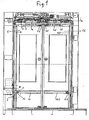
- in einer aus dem Fahrzeuginneren gesehenen Gesamtansicht eine zweiflügelige Schwenkschiebetür in einer in der Höhe verkürzten Darstellung;
- Fig. 2
- einen Schnitt nach der Linie B-B in
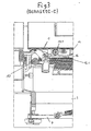
Fig. 1 in vergrößerter Darstellung; - Fig. 3
- einen Schnitt nach der Linie C-C in
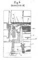
Fig. 1 in vergrößerter Darstellung; - Fig. 4
- den Bereich X in
Fig. 1 in vergrößerter Darstellung; - Fig. 5
- einen Schnitt nach der Linie A-A in
Fig. 4 ; - Fig. 6
- einen Schnitt nach der Linie B-B' in gegenüber
Fig. 2 stärker vergrößerter Darstellung. - Die in den Zeichnungen dargestellte Schwenkschiebetür ist als zweiflügelige Tür ausgebildet und besitzt ein erstes Türblatt 1 und ein zweites Türblatt 1A. Im folgenden werden die der ersten und zweiten Türhälfte entsprechenden Bauteile mit den gleichen Bezugsziffern bezeichnet, wobei die dem zweiten Türblatt zugeordneten Bauteile jeweils durch A gekennzeichnet sind.
- Das Türblatt 1 ist mittels eines drehsteifen Tragarms 1.1 über ein Parallelogrammgestänge, das aus einem Schwenkarm 9 und einem Stützarm 9.1 besteht, gelenkig mit einem Tragglied 8 verbunden, das als Rollenschlitten oder auch als Kugelhülse ausgebildet sein kann. Das Tragglied 8 ist auf einem Führungselement 3 geführt, das als Rundstange oder Führungsschiene ausgebildet sein kann. Das Führungselement 3 ist fest mit dem Türportal 2 verbunden. Das Tragglied 8 ist von einer beispielsweise als Elektromotor ausgebildeten Antriebsvorrichtung 6 aus über einen Nockenriementrieb 7 in seiner Längsrichtung auf dem Führungselement 3 verschiebbar.
- Die Querbewegung des Türblatts 1 wird mit der Längsbewegung durch eine mit dem Türportal 2 fest verbundene Führungsschiene 5 koordiniert, in welche eine am Schwenkarm 9 angeordnete Führungsrolle 5.1 eingreift. Aufgrund der Ausbildung der Führungsschiene 5 wird über den Schwenkarm 9 der Tragarm 1.1 und mit ihm das Türblatt 1 bei der Längsbewegung nach außen geführt. Die Querbewegung des Türblatts 1 wird unterstützt, indem die Reaktionskraft der Antriebsvorrichtung 6 über ein als Stange ausgebildetes Koppelelement 4 auf ein Übertragungselement 4.1 für eine Drehbewegung übertragen wird, das als Schwenkhebel ausgebildet ist und über eine Koppelstange 15 mit einem oberen Rollenhebel 11 verbunden ist, der von einer vertikal verlaufenden und drehbar am Türportal 2 gelagerten Drehsäule 10 getragen wird. Wie den Zeichnungen zu entnehmen, wird durch diese Vorrichtung die Reaktionskraft der Antriebsvorrichtung 6 in ein Drehmoment umgewandelt, das eine Drehbewegung der Drehsäule 10 erzeugt, wodurch, wie weiter unten noch erläutert, eine Querkraft auf das Türblatt 1 im Bereich der Nebenschließkante des Türblatts 1 ausgeübt wird, die das Türblatt an dieser Stelle nach außen führt. Gleichzeitig wird an dieser Stelle eine Abstützung und Verriegelungsmöglichkeit geschaffen, mittels der erreicht wird, dass im geschlossenen Zustand der Tür das Türblatt 1 sowohl nach innen als auch nach außen abgestützt ist und keine Bewegungen in der Querrichtung ausführen kann.
- Um diese zu erreichen, wird in erster Linie dafür gesorgt, dass in an sich bekannter Weise im geschlossenen Zustand die Koppelstange 15 und der Schwenkhebel 4.1 in oder kurz hinter einer Totpunktlage liegen, wie beispielsweise in
Fig. 6 zu erkennen, derart, dass somit die Drehbewegung der Drehsäule 10 blockiert ist. - Weiterhin trägt der mit der Drehsäule 10 verbundene obere Rollenhebel 11 eine Rolle 11.1, welche im letzten Abschnitt der Schließbewegung des Türblatts 1 in ein Formeinlaufstück 16 gelangt, in dem sie in der Geschlossenstellung des Türblatts 1 hinter einem Kurvenstück 16.1 festgehalten ist. Auf diese Weise ist der obere Teil des Türblatts 1 in der Geschlossenstellung verriegelt. Bei der Öffnungsbewegung des Türblatts 1 läuft die Rolle 11.1 in eine am Türblatt 1 angeordnete Führungsschiene 13 ein.
- Im unteren Bereich des Türblatts 1 ist an der Drehsäule 10 ein unterer Rollenhebel 12 angeordnet. Diese Anordnung ist insbesondere den
Fig. 4 und 5 zu entnehmen. Der untere Rollenhebel 12 trägt drei Rollen 12.1, 12.2 und 12.3, von denen zwei Rollen 12.1 und 12.2 einander gegenüberliegen, wobei eine erste, dem Türblatt 1 zugewandte Rolle 12.1 in einer am unteren Teil des Türblatts 1 angeordneten Führungsschiene 14 läuft und im letzten Abschnitt der Schließbewegung in ein am Ende der unteren Führungsschiene 14 angeordnetes Aufnahmestück 17 einläuft, das eine äußere Seitenwand 17.1 besitzt, an der sich die zweite, außerhalb des Aufnahmestücks 17 liegende Rolle 12.2 von außen her abstützt. Die dritte am Rollenhebel 12 angeordnete Rolle 12.3 liegt im geschlossenen Zustand des Türblatts 1 einer Stirnwand 17.2 des Aufnahmestücks 17 außen gegenüber.
InFig. 5 ist der Rollenhebel 12 mit den Rollen 12.1 bis 12.3 im geschlossenen Zustand der Tür dargestellt. Man erkennt, dass in dieser Stellung das Türblatt 1 gegen Querbewegungen nach außen und nach innen verriegelt ist. Bei der Öffnungsbewegung schwenkt der Rollenhebel 12 aufgrund der Drehbewegung der Drehsäule 10 nach außen, und die Rollen 12.2 und 12.3 geraten somit in eine Lage parallel zur Führunsschiene 14, an der sie im weiteren Verlauf der Öffnungsbewegung des Türblatts 1 geführt entlanglaufen.
Claims (3)
- Vorrichtung zur Verriegelung einer Schwenkschiebetür für Fahrzeuge zur Personenbeförderung, insbesondere Fahrzeuge des öffentlichen Personennahverkehrs, bei welcher mindestens ein Türblatt (1, 1A) in seiner Längsrichtung auf einem Führungselement (3) verschiebbar und quer zur Ebene des Türblatts (1,1A) bewegbar ist, wobei die Längsbewegung des Türblatts (1,1A) mit der Querbewegung durch eine mit dem Türportal (2) fest verbundene Führungsschiene (5) koordiniert ist, in welche ein mit dem Türblatt (1,1A) verbundenes Führungsmittel (5.1) eingreift und bei der die Abtriebskraft einer Antriebsvorrichtung (6) am Türblatt (1,1A) in Richtung des Führungselements (3) angreift und Mittel zur Erzeugung oder Unterstützung der Querbewegung vorgesehen sind und bei welcher am Türportal (2) eine vertikal verlaufende Drehsäule (10) drehbar gelagert ist, an der ein oberer und ein unterer Rollenhebel (11, 12) angeordnet sind, die jeweils in am Türblatt (1, 1A) im oberen bzw. unteren Bereich angeordnete Führungen (13, 14) eingreifen, und die Drehsäule (10) mit den Mitteln zur Erzeugung oder Unterstützung der Querbewegung über eine Koppelstange (15) und ein Übertragungselement (4.1) für eine Drehbewegung gekoppelt ist, gekennzeichnet durch folgende Merkmale:a) In der Geschlossenstellung des Türblatts (1,1A) befinden sich Koppelstange (15) und das Übertragungselement (4.1) für eine Drehbewegung in oder kurz hinter einer Totpunktlage, derart, dass die Drehbewegung der Drehsäule (10) blockiert ist;b) Der obere Rollenhebel (11) trägt eine Rolle (11.1), welche im letzten Abschnitt der Schließbewegung des Türblatts (1,1A) in ein Formeinlaufstück (16) gelangt, in dem sie in der Geschlossenstellung des Türblatts (1,1A) hinter einem Kurvenstück (16.1) festgehalten ist;c) Der untere Rollenhebel (12) trägt mindestens zwei in Querrichtung zum Türblatt (1, 1A) einander gegenüberliegende Rollen (12.1, 12.2), von denen eine erste, dem Türblatt (1, 1 A) zugewandte Rolle (12.1) in der unteren Führungsschiene (14) läuft und im letzten Abschnitt der Schließbewegung in ein am Ende der unteren Führungsschiene (14) angeordnetes Aufnahmestück (17) einläuft, mit einer äußeren Seitenwand (17.1), an der sich die zweite, außerhalb des Aufnahmestücks (17) liegende Rolle (12.2) von außen her abstützt.
- Vorrichtung nach Anspruch 1, dadurch gekennzeichnet, dass der untere Rollenhebel (12) eine dritte Rolle (12.3) trägt, die im geschlossenen Zustand des Türblatts (1,1A) einer Stirnwand (17.2) des Aufnahmestücks (17) außen gegenüberliegt.
- Vorrichtung nach Anspruch 1 oder 2, dadurch gekennzeichnet, dass Mittel zur Unterstützung der Querbewegung des Türblatts (1, 1A) vorgesehen sind, die ein Koppelelement (4, 4A) aufweisen, durch welches die Reaktionskraft der Antriebsvorrichtung (6) auf das als Schwenkhebel (4.1, 4.1 A) ausgebildete Übertragungselement (4.1) für eine Drehbewegung übertragen wird.
Applications Claiming Priority (2)
| Application Number | Priority Date | Filing Date | Title |
|---|---|---|---|
| DE202004002908U DE202004002908U1 (de) | 2004-02-25 | 2004-02-25 | Vorrichtung zur Verriegelung einer Schwenkschiebetür für Fahrzeuge zur Personenbeförderung, insbesondere Fahrzeuge des öffentlichen Personennahverkehrs |
| DE202004002908U | 2004-02-25 |
Publications (2)
| Publication Number | Publication Date |
|---|---|
| EP1568563A1 EP1568563A1 (de) | 2005-08-31 |
| EP1568563B1 true EP1568563B1 (de) | 2008-05-28 |
Family
ID=32309209
Family Applications (1)
| Application Number | Title | Priority Date | Filing Date |
|---|---|---|---|
| EP05001876A Expired - Lifetime EP1568563B1 (de) | 2004-02-25 | 2005-01-29 | Vorrichtung zur Verriegelung einer Schwenkschiebetür für Fahrzeuge zur Personenbeförderung, insbesondere Fahrzeuge des öffentlichen Personennahverkehrs |
Country Status (3)
| Country | Link |
|---|---|
| EP (1) | EP1568563B1 (de) |
| AT (1) | ATE396898T1 (de) |
| DE (2) | DE202004002908U1 (de) |
Cited By (1)
| Publication number | Priority date | Publication date | Assignee | Title |
|---|---|---|---|---|
| DE202009013392U1 (de) | 2009-10-21 | 2011-03-03 | Gebr. Bode Gmbh & Co. Kg | Verriegelung durch Kinematik |
Families Citing this family (11)
| Publication number | Priority date | Publication date | Assignee | Title |
|---|---|---|---|---|
| AT501468B8 (de) * | 2005-02-17 | 2007-02-15 | Knorr Bremse Gmbh | Schwenkschiebetür |
| DE102010027136B4 (de) * | 2010-07-14 | 2025-12-31 | Knorr-Bremse Gmbh | Vorrichtung zum Durchführen einer Öffnungsbewegung einer Tür |
| EP2500499B1 (de) * | 2011-03-18 | 2017-06-21 | Gebr. Bode GmbH & Co. KG | Verriegelungssystem mit Hebeln |
| AT514885B1 (de) * | 2013-09-23 | 2015-10-15 | Knorr Bremse Ges Mit Beschränkter Haftung | Schwenkschiebetürmodul für ein Schienenfahrzeug mit verbesserter Übertotpunktverriegelung |
| CN104912426A (zh) * | 2014-03-14 | 2015-09-16 | 林会明 | 塞拉门的新型转换机构 |
| CN103924900B (zh) * | 2014-04-09 | 2015-12-30 | 江苏大学 | 一种基于虚拟直线移动导轨塞拉门塞拉运动机构装置 |
| JP6346835B2 (ja) * | 2014-09-22 | 2018-06-20 | ナブテスコ株式会社 | プラグドア開閉装置およびプラグドア装置 |
| AT14843U1 (de) * | 2015-04-01 | 2016-07-15 | Teufl Manfred | Schwenkschiebetür |
| CN108005513B (zh) * | 2018-01-15 | 2023-11-21 | 南京创想电气有限公司 | 一种用于车辆塞拉门的底部锁闭装置 |
| CN112810642B (zh) * | 2019-10-31 | 2022-08-09 | 比亚迪股份有限公司 | 塞拉门承载装置、塞拉门驱动装置和轨道车辆 |
| CN113147814B (zh) * | 2021-04-19 | 2024-04-19 | 南京康尼机电股份有限公司 | 一种大开度塞拉门系统 |
Family Cites Families (4)
| Publication number | Priority date | Publication date | Assignee | Title |
|---|---|---|---|---|
| DE58905915D1 (de) * | 1989-06-02 | 1993-11-18 | Ife Gmbh | Schwenkschiebetür für Fahrzeuge. |
| DE4133179A1 (de) | 1991-10-07 | 1993-04-08 | Bode & Co Geb | Vorrichtung zur bewegung einer schwenkschiebetuer fuer fahrzeuge zur personenbefoerderung, insbesondere schienenfahrzeuge |
| TR199701164A2 (xx) * | 1996-10-21 | 1998-06-22 | Ife Industrie-Einrichtungen Fertigungs Aktiengesellschaft | Ara�lar i�in s�rg�l� kap�. |
| AT409616B (de) * | 1998-02-10 | 2002-09-25 | Ife Gmbh | Schwenkschiebetür für ein fahrzeug |
-
2004
- 2004-02-25 DE DE202004002908U patent/DE202004002908U1/de not_active Expired - Lifetime
-
2005
- 2005-01-29 DE DE502005004237T patent/DE502005004237D1/de not_active Expired - Fee Related
- 2005-01-29 EP EP05001876A patent/EP1568563B1/de not_active Expired - Lifetime
- 2005-01-29 AT AT05001876T patent/ATE396898T1/de not_active IP Right Cessation
Cited By (2)
| Publication number | Priority date | Publication date | Assignee | Title |
|---|---|---|---|---|
| DE202009013392U1 (de) | 2009-10-21 | 2011-03-03 | Gebr. Bode Gmbh & Co. Kg | Verriegelung durch Kinematik |
| EP2314494A1 (de) | 2009-10-21 | 2011-04-27 | Gebr. Bode GmbH & Co. KG | Verriegelung durch Kinematik |
Also Published As
| Publication number | Publication date |
|---|---|
| DE202004002908U1 (de) | 2004-05-06 |
| EP1568563A1 (de) | 2005-08-31 |
| ATE396898T1 (de) | 2008-06-15 |
| DE502005004237D1 (de) | 2008-07-10 |
Similar Documents
| Publication | Publication Date | Title |
|---|---|---|
| EP1914372B1 (de) | Als Schiebetür oder Schwenkschiebetür ausgebildete Fahrgasttür für Fahrzeuge des öffentlichen Personenverkehrs | |
| EP1527975B1 (de) | Schwenkschiebetür für Fahrzeuge, insbesondere Fahrgasttür für Fahrzeuge des öffentlichen Personennahverkehrs | |
| EP1767427B1 (de) | Einrichtung zur Bewegung des Türblattes einer Schwenkschiebetür, insbesondere für Schienenfahrzeuge | |
| EP1584535B1 (de) | Schwenkschiebetür für Schienenfahrzeuge | |
| EP1767388B1 (de) | Schwenkschiebetür für Fahrzeuge, insbesondere Fahrgasttür für Fahrzeuge des offentlichen Personnenverkehrs | |
| EP1568563B1 (de) | Vorrichtung zur Verriegelung einer Schwenkschiebetür für Fahrzeuge zur Personenbeförderung, insbesondere Fahrzeuge des öffentlichen Personennahverkehrs | |
| DE29905681U1 (de) | Schwenkschiebetür für Fahrzeuge, insbesondere Fahrzeuge des öffentlichen Personennahverkehrs | |
| EP1752602B1 (de) | Fenster mit Hubschiebefunktion | |
| DE202005015166U1 (de) | Schwenkschiebetür für Fahrzeuge, insbesondere Fahrgasttür für Fahrzeuge des öffentlichen Personennahverkehrs | |
| EP1280690A1 (de) | Zweiflüglige schwenkschiebetür für fahrzeuge zur personenbeförderung | |
| EP1767389B1 (de) | Schwenkschiebetür für Fahrzeuge, insbesondere Fahrgasttür für Fahrzeuge des öffentlichen Personnenverkehrs | |
| DE102004059501B3 (de) | Fahrzeugtür für Kraftfahrzeuge | |
| DE202016101709U1 (de) | Schwenkschiebetür | |
| EP1176279B1 (de) | Sektionaltor | |
| DE202005007984U1 (de) | Schiebetür oder Schwenkschiebetür für Fahrzeuge des öffentlichen Personennah- und -fernverkehrs | |
| DE102009045796A1 (de) | Tor mit seitlichem Antrieb | |
| AT521810B1 (de) | Zugmitteltrieb zum Antreiben und Verriegeln von Türen für Schienenfahrzeuge | |
| EP1635024A2 (de) | Schwenktür für Fahrzeuge des öffentlichen Personenverkehrs, insbesondere für Busse | |
| DE10052228B4 (de) | Einrichtung zum Verriegeln eines Schwenktürflügels | |
| EP3235994B1 (de) | Antriebsvorrichtung für ein anzutreibendes element | |
| EP1380718B1 (de) | Vorrichtung zur automatischen Betätigung einer Kraftfahrzeugschiebetür | |
| AT526090B1 (de) | Schwenkschiebetürblatt | |
| EP1724138A2 (de) | Schiebetür oder Schwenkschiebetür für Fahrzeuge des öffentlichen Personennah- und fernverkehrs | |
| EP1767428B1 (de) | Tragführung für Schwenkschiebetüren für Schienenfahrzeuge mit mindestens einem Türblatt | |
| DE102009056878A1 (de) | Tür für einen Kraftwagen |
Legal Events
| Date | Code | Title | Description |
|---|---|---|---|
| PUAI | Public reference made under article 153(3) epc to a published international application that has entered the european phase |
Free format text: ORIGINAL CODE: 0009012 |
|
| AK | Designated contracting states |
Kind code of ref document: A1 Designated state(s): AT BE BG CH CY CZ DE DK EE ES FI FR GB GR HU IE IS IT LI LT LU MC NL PL PT RO SE SI SK TR |
|
| AX | Request for extension of the european patent |
Extension state: AL BA HR LV MK YU |
|
| 17P | Request for examination filed |
Effective date: 20050907 |
|
| AKX | Designation fees paid |
Designated state(s): AT BE BG CH CY CZ DE DK EE ES FI FR GB GR HU IE IS IT LI LT LU MC NL PL PT RO SE SI SK TR |
|
| GRAP | Despatch of communication of intention to grant a patent |
Free format text: ORIGINAL CODE: EPIDOSNIGR1 |
|
| GRAS | Grant fee paid |
Free format text: ORIGINAL CODE: EPIDOSNIGR3 |
|
| GRAA | (expected) grant |
Free format text: ORIGINAL CODE: 0009210 |
|
| AK | Designated contracting states |
Kind code of ref document: B1 Designated state(s): AT BE BG CH CY CZ DE DK EE ES FI FR GB GR HU IE IS IT LI LT LU MC NL PL PT RO SE SI SK TR |
|
| REG | Reference to a national code |
Ref country code: GB Ref legal event code: FG4D Free format text: NOT ENGLISH |
|
| REG | Reference to a national code |
Ref country code: CH Ref legal event code: EP |
|
| REF | Corresponds to: |
Ref document number: 502005004237 Country of ref document: DE Date of ref document: 20080710 Kind code of ref document: P |
|
| REG | Reference to a national code |
Ref country code: IE Ref legal event code: FG4D Free format text: LANGUAGE OF EP DOCUMENT: GERMAN |
|
| PG25 | Lapsed in a contracting state [announced via postgrant information from national office to epo] |
Ref country code: SI Free format text: LAPSE BECAUSE OF FAILURE TO SUBMIT A TRANSLATION OF THE DESCRIPTION OR TO PAY THE FEE WITHIN THE PRESCRIBED TIME-LIMIT Effective date: 20080528 |
|
| PG25 | Lapsed in a contracting state [announced via postgrant information from national office to epo] |
Ref country code: ES Free format text: LAPSE BECAUSE OF FAILURE TO SUBMIT A TRANSLATION OF THE DESCRIPTION OR TO PAY THE FEE WITHIN THE PRESCRIBED TIME-LIMIT Effective date: 20080908 Ref country code: FI Free format text: LAPSE BECAUSE OF FAILURE TO SUBMIT A TRANSLATION OF THE DESCRIPTION OR TO PAY THE FEE WITHIN THE PRESCRIBED TIME-LIMIT Effective date: 20080528 |
|
| PG25 | Lapsed in a contracting state [announced via postgrant information from national office to epo] |
Ref country code: NL Free format text: LAPSE BECAUSE OF FAILURE TO SUBMIT A TRANSLATION OF THE DESCRIPTION OR TO PAY THE FEE WITHIN THE PRESCRIBED TIME-LIMIT Effective date: 20080528 |
|
| NLV1 | Nl: lapsed or annulled due to failure to fulfill the requirements of art. 29p and 29m of the patents act | ||
| PG25 | Lapsed in a contracting state [announced via postgrant information from national office to epo] |
Ref country code: IS Free format text: LAPSE BECAUSE OF FAILURE TO SUBMIT A TRANSLATION OF THE DESCRIPTION OR TO PAY THE FEE WITHIN THE PRESCRIBED TIME-LIMIT Effective date: 20080928 |
|
| REG | Reference to a national code |
Ref country code: IE Ref legal event code: FD4D |
|
| PG25 | Lapsed in a contracting state [announced via postgrant information from national office to epo] |
Ref country code: SE Free format text: LAPSE BECAUSE OF FAILURE TO SUBMIT A TRANSLATION OF THE DESCRIPTION OR TO PAY THE FEE WITHIN THE PRESCRIBED TIME-LIMIT Effective date: 20080828 Ref country code: DK Free format text: LAPSE BECAUSE OF FAILURE TO SUBMIT A TRANSLATION OF THE DESCRIPTION OR TO PAY THE FEE WITHIN THE PRESCRIBED TIME-LIMIT Effective date: 20080528 Ref country code: CZ Free format text: LAPSE BECAUSE OF FAILURE TO SUBMIT A TRANSLATION OF THE DESCRIPTION OR TO PAY THE FEE WITHIN THE PRESCRIBED TIME-LIMIT Effective date: 20080528 Ref country code: IE Free format text: LAPSE BECAUSE OF FAILURE TO SUBMIT A TRANSLATION OF THE DESCRIPTION OR TO PAY THE FEE WITHIN THE PRESCRIBED TIME-LIMIT Effective date: 20080528 Ref country code: LT Free format text: LAPSE BECAUSE OF FAILURE TO SUBMIT A TRANSLATION OF THE DESCRIPTION OR TO PAY THE FEE WITHIN THE PRESCRIBED TIME-LIMIT Effective date: 20080528 Ref country code: PT Free format text: LAPSE BECAUSE OF FAILURE TO SUBMIT A TRANSLATION OF THE DESCRIPTION OR TO PAY THE FEE WITHIN THE PRESCRIBED TIME-LIMIT Effective date: 20081028 |
|
| PG25 | Lapsed in a contracting state [announced via postgrant information from national office to epo] |
Ref country code: SK Free format text: LAPSE BECAUSE OF FAILURE TO SUBMIT A TRANSLATION OF THE DESCRIPTION OR TO PAY THE FEE WITHIN THE PRESCRIBED TIME-LIMIT Effective date: 20080528 Ref country code: RO Free format text: LAPSE BECAUSE OF FAILURE TO SUBMIT A TRANSLATION OF THE DESCRIPTION OR TO PAY THE FEE WITHIN THE PRESCRIBED TIME-LIMIT Effective date: 20080528 |
|
| PLBE | No opposition filed within time limit |
Free format text: ORIGINAL CODE: 0009261 |
|
| STAA | Information on the status of an ep patent application or granted ep patent |
Free format text: STATUS: NO OPPOSITION FILED WITHIN TIME LIMIT |
|
| PG25 | Lapsed in a contracting state [announced via postgrant information from national office to epo] |
Ref country code: BG Free format text: LAPSE BECAUSE OF FAILURE TO SUBMIT A TRANSLATION OF THE DESCRIPTION OR TO PAY THE FEE WITHIN THE PRESCRIBED TIME-LIMIT Effective date: 20080828 Ref country code: EE Free format text: LAPSE BECAUSE OF FAILURE TO SUBMIT A TRANSLATION OF THE DESCRIPTION OR TO PAY THE FEE WITHIN THE PRESCRIBED TIME-LIMIT Effective date: 20080528 |
|
| 26N | No opposition filed |
Effective date: 20090303 |
|
| PG25 | Lapsed in a contracting state [announced via postgrant information from national office to epo] |
Ref country code: MC Free format text: LAPSE BECAUSE OF NON-PAYMENT OF DUE FEES Effective date: 20090131 Ref country code: IT Free format text: LAPSE BECAUSE OF FAILURE TO SUBMIT A TRANSLATION OF THE DESCRIPTION OR TO PAY THE FEE WITHIN THE PRESCRIBED TIME-LIMIT Effective date: 20080528 |
|
| REG | Reference to a national code |
Ref country code: CH Ref legal event code: PL |
|
| GBPC | Gb: european patent ceased through non-payment of renewal fee |
Effective date: 20090129 |
|
| PG25 | Lapsed in a contracting state [announced via postgrant information from national office to epo] |
Ref country code: CH Free format text: LAPSE BECAUSE OF NON-PAYMENT OF DUE FEES Effective date: 20090131 Ref country code: LI Free format text: LAPSE BECAUSE OF NON-PAYMENT OF DUE FEES Effective date: 20090131 Ref country code: DE Free format text: LAPSE BECAUSE OF NON-PAYMENT OF DUE FEES Effective date: 20090801 |
|
| REG | Reference to a national code |
Ref country code: FR Ref legal event code: ST Effective date: 20091030 |
|
| PG25 | Lapsed in a contracting state [announced via postgrant information from national office to epo] |
Ref country code: GB Free format text: LAPSE BECAUSE OF NON-PAYMENT OF DUE FEES Effective date: 20090129 |
|
| PG25 | Lapsed in a contracting state [announced via postgrant information from national office to epo] |
Ref country code: BE Free format text: LAPSE BECAUSE OF NON-PAYMENT OF DUE FEES Effective date: 20090131 |
|
| PG25 | Lapsed in a contracting state [announced via postgrant information from national office to epo] |
Ref country code: FR Free format text: LAPSE BECAUSE OF NON-PAYMENT OF DUE FEES Effective date: 20090202 |
|
| PG25 | Lapsed in a contracting state [announced via postgrant information from national office to epo] |
Ref country code: PL Free format text: LAPSE BECAUSE OF FAILURE TO SUBMIT A TRANSLATION OF THE DESCRIPTION OR TO PAY THE FEE WITHIN THE PRESCRIBED TIME-LIMIT Effective date: 20080528 |
|
| PG25 | Lapsed in a contracting state [announced via postgrant information from national office to epo] |
Ref country code: AT Free format text: LAPSE BECAUSE OF NON-PAYMENT OF DUE FEES Effective date: 20090129 |
|
| PG25 | Lapsed in a contracting state [announced via postgrant information from national office to epo] |
Ref country code: GR Free format text: LAPSE BECAUSE OF FAILURE TO SUBMIT A TRANSLATION OF THE DESCRIPTION OR TO PAY THE FEE WITHIN THE PRESCRIBED TIME-LIMIT Effective date: 20080829 |
|
| PG25 | Lapsed in a contracting state [announced via postgrant information from national office to epo] |
Ref country code: LU Free format text: LAPSE BECAUSE OF NON-PAYMENT OF DUE FEES Effective date: 20090129 |
|
| PG25 | Lapsed in a contracting state [announced via postgrant information from national office to epo] |
Ref country code: HU Free format text: LAPSE BECAUSE OF FAILURE TO SUBMIT A TRANSLATION OF THE DESCRIPTION OR TO PAY THE FEE WITHIN THE PRESCRIBED TIME-LIMIT Effective date: 20081129 |
|
| PG25 | Lapsed in a contracting state [announced via postgrant information from national office to epo] |
Ref country code: TR Free format text: LAPSE BECAUSE OF FAILURE TO SUBMIT A TRANSLATION OF THE DESCRIPTION OR TO PAY THE FEE WITHIN THE PRESCRIBED TIME-LIMIT Effective date: 20080528 |
|
| PG25 | Lapsed in a contracting state [announced via postgrant information from national office to epo] |
Ref country code: CY Free format text: LAPSE BECAUSE OF FAILURE TO SUBMIT A TRANSLATION OF THE DESCRIPTION OR TO PAY THE FEE WITHIN THE PRESCRIBED TIME-LIMIT Effective date: 20080528 |