EP1568440B1 - Outil d'usinage pour enlèvement de copeaux - Google Patents
Outil d'usinage pour enlèvement de copeaux Download PDFInfo
- Publication number
- EP1568440B1 EP1568440B1 EP04030401A EP04030401A EP1568440B1 EP 1568440 B1 EP1568440 B1 EP 1568440B1 EP 04030401 A EP04030401 A EP 04030401A EP 04030401 A EP04030401 A EP 04030401A EP 1568440 B1 EP1568440 B1 EP 1568440B1
- Authority
- EP
- European Patent Office
- Prior art keywords
- tool according
- equal
- longitudinal axis
- carrier part
- central longitudinal
- Prior art date
- Legal status (The legal status is an assumption and is not a legal conclusion. Google has not performed a legal analysis and makes no representation as to the accuracy of the status listed.)
- Expired - Lifetime
Links
Images

Classifications
-
- B—PERFORMING OPERATIONS; TRANSPORTING
- B24—GRINDING; POLISHING
- B24D—TOOLS FOR GRINDING, BUFFING OR SHARPENING
- B24D9/00—Wheels or drums supporting in exchangeable arrangement a layer of flexible abrasive material, e.g. sandpaper
- B24D9/08—Circular back-plates for carrying flexible material
-
- B—PERFORMING OPERATIONS; TRANSPORTING
- B24—GRINDING; POLISHING
- B24B—MACHINES, DEVICES, OR PROCESSES FOR GRINDING OR POLISHING; DRESSING OR CONDITIONING OF ABRADING SURFACES; FEEDING OF GRINDING, POLISHING, OR LAPPING AGENTS
- B24B23/00—Portable grinding machines, e.g. hand-guided; Accessories therefor
- B24B23/02—Portable grinding machines, e.g. hand-guided; Accessories therefor with rotating grinding tools; Accessories therefor
- B24B23/028—Angle tools
Definitions
- the invention relates to a tool for machining according to the preamble of claim 1.
- Such known tools are preferably operated with a working part, which is designed as an abrasive on a base, that is highly elastic.
- the chip removal to be performed with these working parts are very high, which leads to a very rapid heating of the working part.
- the already designed to eliminate this problem generically supporting members have straight radially outwardly directed or concave in the direction of rotation curved flow channels with an air inlet on the central longitudinal axis side facing that do not lead to a satisfactory cooling.
- the invention is therefore based on the object, the tool in such a way that a satisfactory cooling of the working part is achieved.
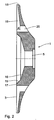
- the tool shown in the drawing consists in its basic structure of a support member 1 in the form of a support plate and a working part 2.
- the support member 1 is integrally formed and is usually made of an elastic plastic. It has an annular contact surface 3. Concentric with its central longitudinal axis 4, the support member 1 is provided with a cylindrical passage opening 5, through which a connectable to a drive tool, not shown drive shaft 6 can be pushed.
- the drive shaft 6 has an external thread 7 at its free end.
- the actual working part 2 is also formed circular disk-shaped and has a counter-abutment surface 8, which comes into contact with the mounting surface 3 in the attachment of the working part 2 on the support member 1.
- the working part 2 has approximately the diameter or the circumference of the support part 1.
- the working part 2 is formed by an abrasive 9 on pad 10, wherein the counter-abutment surface 8 is formed on the side facing away from the abrasive 9 side of the pad 10.
- a nut 11 is provided with an external thread 7 adapted internal thread 12.
- the shaft 6 is inserted with its outer thread 7 as shown in Fig.
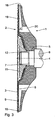
- the abutment surface 3 of the support member 1 is formed essentially by ribs 13 and intermediate ribs 14.
- the inner circumference 15 of the contact surface 3 delimits a serving for receiving the nut 11, from the contact surface 3 recessed, recess 16 into which the opening 5 opens.
- the ribs 13 are connected to each other by a narrow annular web 17, on which the assembled working part 2 tightly rests over the entire circumference 15, so that there is no connection between the recess 16 and the outer area of the contact surface 3.
- the supply channels 20 have - as shown in FIG. 1 reveals - transverse to the axis 4, the cross section of a slot 21. They form insofar as the radial to the axis 4 inner initial region of the flow channels 19 and thus also a part of these.
- two adjacent radii 22, 23 of two adjacent flow channels 19 enclose a pitch angle ⁇ .
- These radii 22, 23 pass through the central longitudinal axis 4 of the support member 1 and through the lying on the outer periphery 18 center 24 of a flow channel 19.
- the center 24 of a flow channel 19 is interposed by the lying in this area Rib 14 formed.
- the pitch angle a With the uniform distribution of the channels 19 over the circumference of the support member 1, this means that between 4 and 36 and preferably between 12 and 36 flow channels 19 are provided.
- the pitch angle a becomes smaller, that is, smaller. H. the number of flow channels 19 and thus also the number of ribs 13 and possibly the intermediate ribs 14 larger.
- the lead angle b is a lead angle, because it indicates how far the slot 21, so the initial region of the flow channel 19, relative to the defined by the center 24 on the outer periphery 18 outlet region relative to the Direction of rotation 27 leads.
- the lead angle b 5 ° ⁇ b ⁇ 45 ° and preferably 5 ° ⁇ b ⁇ 25 °.
- the flow channels 19 exit at the outer periphery 18 of the support member 1 approximately radially to the axis 4 from. Starting from the formed by the respective slot 21 initial region of the flow channels 19 are these - as also Fig. 1 reveals - curved in the direction of rotation 27 of the support member 1, which results from the previously described lead angle b. In other words, the flow channels 19 are formed concave against the direction of rotation 27.
- the guided through the center 25 of the slot 21 radius 26 and drawn through the center 25 of the elongated hole 21 central longitudinal axis 28 of the slot 21 include an inclination angle c through which the inclination of the slot 21 and thus the beginning Region of each flow channel 19 is indicated with respect to the radial direction, wherein the slot 21 is seen from the axis 4 to the outer periphery 18 out towards the direction of rotation 27 inclined.
- the inclination angle c the following applies: 5 ° ⁇ c ⁇ 90 ° and preferably 20 ° ⁇ c ⁇ 60 °.
- the axial height d of the channels 19 decreases towards the outside.
- the radially outward in the circumferential direction of the support member 1 increasing width e of the flow channels 19 again at least partially, possibly completely compensated, so that the Cross-section of the flow channels 19 from its initial region 21 to the outer periphery 18 is approximately constant. Furthermore, this ensures that the existing elastic plastic support member 1 in the region of its outer periphery 18 is not too stiff.
- the shape of the flow channels 19 causes a particularly intensive air intake and a correspondingly intensive air transport radially outwards; the air flows with high turbulence and thus with a high heat transfer coefficient past the counter-abutment surface 8 of the working part 2.
- the cooling is so intense.
Landscapes
- Engineering & Computer Science (AREA)
- Mechanical Engineering (AREA)
- Polishing Bodies And Polishing Tools (AREA)
- Turning (AREA)
- Auxiliary Devices For Machine Tools (AREA)
- Scissors And Nippers (AREA)
- Feeding Of Articles To Conveyors (AREA)
- Finish Polishing, Edge Sharpening, And Grinding By Specific Grinding Devices (AREA)
Claims (16)
- Outil d'usinage pourvu d'un élément de support à entraînement rotatif (1) autour d'un axe de longueur moyenne (4) dans une direction de rotation (27), avec un élément de travail circulaire (2) pour un travail de serrage, et des moyens de connexion pour la connexion amovible coaxiale de l'élément de travail (2) à l'élément de support (1), l'élément de support (1) comprenant une surface de butée (3) pour l'élément de travail (2), l'élément de travail (2) comprenant une surface de butée opposée (8) pour venir en butée sur la surface de butée (3), et des canaux d'écoulement (19) étant développés dans la surface de butée (3), essentiellement à partir de l'axe de longueur moyenne (4) vers l'extérieur en direction de la surface de butée opposée (8), dans lesquels débouchent des canaux d'alimentation (20) développés dans l'élément de support (1), caractérisé en ce que chaque canal d'alimentation (20) débouche dans une zone de départ située à l'intérieur par rapport à l'axe de longueur moyenne (4) d'un canal d'écoulement (19), en ce que la zone de départ est développée de manière inclinée contre la direction de rotation (27) autour d'un angle d'inclinaison (c), et en ce que le canal d'écoulement (19) est orienté vers l'extérieur de manière curviligne à partir de la zone de départ dans la direction de rotation (27).
- Outil d'usinage selon la revendication 1, caractérisé en ce que les canaux d'écoulement (19) débouchent approximativement dans la direction radiale de l'élément de support (1).
- Outil d'usinage selon la revendication 1 ou 2, caractérisé en ce que l'angle d'inclinaison (c) est compris entre l'axe de longueur moyenne (28) du trou longitudinal (21) et le rayon (26) à travers le centre (25) du trou longitudinal (21).
- Outil d'usinage selon la revendication 3, caractérisé en ce que l'angle d'inclinaison (c) est compris entre 15° ≤ c ≤ 90° et de préférence entre 20° ≤ c ≤ 60°.
- Outil d'usinage selon l'une quelconque des revendications 1 à 4, caractérisé en ce que la zone de départ de chaque canal d'écoulement (19) est développée en tant que trou longitudinal (21) avec un axe de longueur moyenne (28) et un centre (25), et en ce qu'un rayon (26) comprend un angle d'avance (b) à travers le centre (25) du trou longitudinal (21) et un rayon (22) à travers le centre (24) du canal d'écoulement (19) au niveau de l'étendue extérieure (18) de l'élément de support (1).
- Outil d'usinage selon la revendication 5, caractérisé en ce que l'angle d'avance (b) est compris entre 5° ≤ b ≤ 45° et de préférence entre 5° ≤ b ≤ 25°.
- Outil d'usinage selon l'une quelconque des revendications 1 à 6, caractérisé en ce qu'un angle de séparation (a) est compris entre les canaux d'écoulement directement adjacents (19), lequel est compris entre 10° ≤ a ≤ 45° et de préférence entre 10° ≤ a ≤ 30°.
- Outil d'usinage selon l'une quelconque des revendications 1 à 7, caractérisé en ce que les canaux d'écoulement (19) sont partagés en canaux d'écoulement partiels (19a, 19b) dans la zone située à l'extérieur par rapport à l'axe de longueur moyenne (4) de l'élément de support (1) à l'aide d'ailettes intermédiaires (14).
- Outil d'usinage selon l'une quelconque des revendications 1 à 8, caractérisé en ce que les canaux d'écoulement adjacents (19) sont séparés les uns des autres par des ailettes (13).
- Outil d'usinage selon la revendication 9, caractérisé en ce que les ailettes (13) sont reliées entre elles par un listel de piston (17).
- Outil d'usinage selon la revendications 9, caractérisé en ce que la largeur (e) des canaux d'écoulement (19) est beaucoup plus grande que la largeur (f) des ailettes intermédiaires (13).
- Outil d'usinage selon la revendications 8, caractérisé en ce que la largeur (e) des canaux d'écoulement (19) est beaucoup plus grande que la largeur (g) des ailettes intermédiaires (14).
- Outil d'usinage selon l'une quelconque des revendications 1 à 12, caractérisé en ce que la hauteur (d) des canaux d'écoulement (19) est diminuée vers l'extérieur à partir de l'axe de longueur moyenne (4) dans la direction de l'axe de longueur moyenne (4) de l'élément de support (1).
- Outil d'usinage selon l'une quelconque des revendications 1 à 13, caractérisé en ce que la coupe transversale des canaux d'écoulement (19) est constante vers l'extérieur à partir de l'axe de longueur moyenne (4) de l'élément de support (1).
- Outil d'usinage selon l'une quelconque des revendications 1 à 14, caractérisé en ce que l'élément de travail est formé à partir d'un moyen de ponçage (9) sur l'appui (10).
- Outil d'usinage selon l'une quelconque des revendications 1 à 15, caractérisé en ce que l'élément de support (1) est constitué d'un matériau flexible.
Priority Applications (1)
| Application Number | Priority Date | Filing Date | Title |
|---|---|---|---|
| PL04030401T PL1568440T3 (pl) | 2004-02-27 | 2004-12-22 | Narzędzie do obróbki wiórowej |
Applications Claiming Priority (2)
| Application Number | Priority Date | Filing Date | Title |
|---|---|---|---|
| DE102004009443 | 2004-02-27 | ||
| DE102004009443A DE102004009443A1 (de) | 2004-02-27 | 2004-02-27 | Werkzeug zur spanabhebenden Bearbeitung |
Publications (2)
| Publication Number | Publication Date |
|---|---|
| EP1568440A1 EP1568440A1 (fr) | 2005-08-31 |
| EP1568440B1 true EP1568440B1 (fr) | 2006-11-08 |
Family
ID=34745293
Family Applications (1)
| Application Number | Title | Priority Date | Filing Date |
|---|---|---|---|
| EP04030401A Expired - Lifetime EP1568440B1 (fr) | 2004-02-27 | 2004-12-22 | Outil d'usinage pour enlèvement de copeaux |
Country Status (7)
| Country | Link |
|---|---|
| EP (1) | EP1568440B1 (fr) |
| AT (1) | ATE344711T1 (fr) |
| DE (2) | DE102004009443A1 (fr) |
| DK (1) | DK1568440T3 (fr) |
| ES (1) | ES2276216T3 (fr) |
| PL (1) | PL1568440T3 (fr) |
| PT (1) | PT1568440E (fr) |
Cited By (1)
| Publication number | Priority date | Publication date | Assignee | Title |
|---|---|---|---|---|
| WO2025113935A1 (fr) * | 2023-11-29 | 2025-06-05 | Robert Bosch Gmbh | Dispositif de plateau porte-disque |
Families Citing this family (10)
| Publication number | Priority date | Publication date | Assignee | Title |
|---|---|---|---|---|
| ATE377480T1 (de) | 2005-07-05 | 2007-11-15 | Rueggeberg August Gmbh & Co Kg | Werkzeug |
| DE102007014766A1 (de) * | 2007-03-28 | 2008-10-02 | Robert Bosch Gmbh | Exzentertellerschleifer |
| DE102008015180A1 (de) * | 2008-03-20 | 2009-09-24 | Livre Verlags- Und Vertriebs- Gmbh | Schleifelement für eine Schleifmaschine, insbesondere für eine Handschleifmaschine |
| IT1391160B1 (it) * | 2008-08-05 | 2011-11-18 | Bdl S R L | Disco per elettroutensili per il supporto di materiale abrasivo. |
| IT1404215B1 (it) * | 2011-01-25 | 2013-11-15 | Campana Mirco E Figli S N C | Disco per elettroutensili, di supporto di materiale abrasivo |
| JP2015071217A (ja) * | 2013-10-04 | 2015-04-16 | スリーエム イノベイティブ プロパティズ カンパニー | 研磨ディスクを支持するためのパッド |
| DE102014102688A1 (de) * | 2014-02-28 | 2015-09-03 | Adolf Würth GmbH & Co. KG | Poliervorrichtung mit Wärmeabführeinrichtung |
| DE202015100548U1 (de) * | 2015-02-05 | 2015-02-26 | Industrias Tenazit, S.A. De C.V. | Trägerplatte für Lamellenschleifscheiben |
| CN104690649B (zh) * | 2015-02-13 | 2017-04-26 | 浙江工业大学 | 一种人工关节复杂曲面固液二相软性磨粒流湍流加工方法 |
| CN110587499A (zh) * | 2019-09-12 | 2019-12-20 | 扬中市红洲磨具有限公司 | 一种新型钹型砂轮 |
Family Cites Families (6)
| Publication number | Priority date | Publication date | Assignee | Title |
|---|---|---|---|---|
| CA1049265A (fr) * | 1976-09-24 | 1979-02-27 | Miksa Marton | Garniture pour ponceuse rotative aspirante |
| FR2365411A1 (fr) * | 1976-09-27 | 1978-04-21 | Robert Jean | Ponceuse a disque de papier abrasif monte sur un plateau circulaire tournant |
| US4287685A (en) * | 1978-12-08 | 1981-09-08 | Miksa Marton | Pad assembly for vacuum rotary sander |
| DE9002801U1 (de) * | 1990-03-09 | 1990-06-21 | Nied, Hans Rainer, 8760 Miltenberg | Schleifteller für Hand-Schleifmaschinen |
| CZ145893A3 (en) * | 1991-11-02 | 1994-04-13 | Fabritius Hans Josef | Working disk comprising a plate, which might be rotatably clamped in a drilling machine or angle grinding machine and the like |
| DE19945060B4 (de) * | 1999-09-20 | 2010-12-02 | Robert Bosch Gmbh | Schleifhandwerkzeugmaschine |
-
2004
- 2004-02-27 DE DE102004009443A patent/DE102004009443A1/de not_active Withdrawn
- 2004-12-22 ES ES04030401T patent/ES2276216T3/es not_active Expired - Lifetime
- 2004-12-22 EP EP04030401A patent/EP1568440B1/fr not_active Expired - Lifetime
- 2004-12-22 AT AT04030401T patent/ATE344711T1/de active
- 2004-12-22 DE DE502004001950T patent/DE502004001950D1/de not_active Expired - Lifetime
- 2004-12-22 DK DK04030401T patent/DK1568440T3/da active
- 2004-12-22 PT PT04030401T patent/PT1568440E/pt unknown
- 2004-12-22 PL PL04030401T patent/PL1568440T3/pl unknown
Cited By (1)
| Publication number | Priority date | Publication date | Assignee | Title |
|---|---|---|---|---|
| WO2025113935A1 (fr) * | 2023-11-29 | 2025-06-05 | Robert Bosch Gmbh | Dispositif de plateau porte-disque |
Also Published As
| Publication number | Publication date |
|---|---|
| ATE344711T1 (de) | 2006-11-15 |
| ES2276216T3 (es) | 2007-06-16 |
| PL1568440T3 (pl) | 2007-01-31 |
| DE502004001950D1 (de) | 2006-12-21 |
| DK1568440T3 (da) | 2006-12-27 |
| EP1568440A1 (fr) | 2005-08-31 |
| PT1568440E (pt) | 2007-02-28 |
| DE102004009443A1 (de) | 2005-09-15 |
Similar Documents
| Publication | Publication Date | Title |
|---|---|---|
| EP1568440B1 (fr) | Outil d'usinage pour enlèvement de copeaux | |
| DE69817526T2 (de) | Axiallüfter | |
| DE3902666A1 (de) | Drehknetschnecke | |
| EP3611432B1 (fr) | Chauffage pour véhicule | |
| EP2771581B1 (fr) | Roue de ventilateur axial | |
| DE102017109369A1 (de) | Zerspanungswerkzeug mit Kühlmittelumlenkung | |
| EP2282135A2 (fr) | Ventilateur | |
| WO2013127534A1 (fr) | Dispositif permettant de mélanger au moins deux composants fluides, organe rotatif amovible pour mélangeurs, et système formé par ces deux éléments | |
| EP1914402A1 (fr) | Ventilateur axial et procédé destiné à éviter un flux de recirculation | |
| EP3751145A1 (fr) | Dispositif de ventilateur | |
| EP1081388B1 (fr) | Ventilateur | |
| DE2414610B2 (de) | Querstromlüfter | |
| EP3611341B1 (fr) | Aube de turbine avec système de refroidissement | |
| DE102014111055A1 (de) | Lüftereinheit mit einem Axiallüfter | |
| WO2007045355A1 (fr) | Dispositif de transport d'un flux d'air de refroidissement | |
| DE202008000855U1 (de) | Kombinierter Axial-Radial-Lüfter für den Einsatz in beliebigen Lüftungseinrichtungen, z.B. für Dunstabzugshauben | |
| DE3734497A1 (de) | Blasvorrichtung | |
| DE202021101830U1 (de) | Düsenkopf und Düse | |
| EP1384554B1 (fr) | Appareil de sablage | |
| DE102022121237A1 (de) | Bohrvorrichtung mit einer Absaugeinheit | |
| DE102022123882A1 (de) | Vorrichtung zum Leiten von Kühlluft an einer Motoraufnahme für einen Ventilatormotor | |
| DE102009047446A1 (de) | Pumpe | |
| DE4414118A1 (de) | Schubzentrifuge | |
| DE20118332U1 (de) | Düse für Whirlpoolwannen | |
| DE2417506C2 (de) | Axialgebläse für Mähdrescher |
Legal Events
| Date | Code | Title | Description |
|---|---|---|---|
| PUAI | Public reference made under article 153(3) epc to a published international application that has entered the european phase |
Free format text: ORIGINAL CODE: 0009012 |
|
| AK | Designated contracting states |
Kind code of ref document: A1 Designated state(s): AT BE BG CH CY CZ DE DK EE ES FI FR GB GR HU IE IS IT LI LT LU MC NL PL PT RO SE SI SK TR |
|
| AX | Request for extension of the european patent |
Extension state: AL BA HR LV MK YU |
|
| 17P | Request for examination filed |
Effective date: 20050922 |
|
| AKX | Designation fees paid |
Designated state(s): AT BE BG CH CY CZ DE DK EE ES FI FR GB GR HU IE IS IT LI LT LU MC NL PL PT RO SE SI SK TR |
|
| GRAP | Despatch of communication of intention to grant a patent |
Free format text: ORIGINAL CODE: EPIDOSNIGR1 |
|
| GRAS | Grant fee paid |
Free format text: ORIGINAL CODE: EPIDOSNIGR3 |
|
| GRAA | (expected) grant |
Free format text: ORIGINAL CODE: 0009210 |
|
| AK | Designated contracting states |
Kind code of ref document: B1 Designated state(s): AT BE BG CH CY CZ DE DK EE ES FI FR GB GR HU IE IS IT LI LT LU MC NL PL PT RO SE SI SK TR |
|
| PG25 | Lapsed in a contracting state [announced via postgrant information from national office to epo] |
Ref country code: CZ Free format text: LAPSE BECAUSE OF FAILURE TO SUBMIT A TRANSLATION OF THE DESCRIPTION OR TO PAY THE FEE WITHIN THE PRESCRIBED TIME-LIMIT Effective date: 20061108 Ref country code: SK Free format text: LAPSE BECAUSE OF FAILURE TO SUBMIT A TRANSLATION OF THE DESCRIPTION OR TO PAY THE FEE WITHIN THE PRESCRIBED TIME-LIMIT Effective date: 20061108 Ref country code: SI Free format text: LAPSE BECAUSE OF FAILURE TO SUBMIT A TRANSLATION OF THE DESCRIPTION OR TO PAY THE FEE WITHIN THE PRESCRIBED TIME-LIMIT Effective date: 20061108 Ref country code: FI Free format text: LAPSE BECAUSE OF FAILURE TO SUBMIT A TRANSLATION OF THE DESCRIPTION OR TO PAY THE FEE WITHIN THE PRESCRIBED TIME-LIMIT Effective date: 20061108 Ref country code: IE Free format text: LAPSE BECAUSE OF FAILURE TO SUBMIT A TRANSLATION OF THE DESCRIPTION OR TO PAY THE FEE WITHIN THE PRESCRIBED TIME-LIMIT Effective date: 20061108 Ref country code: RO Free format text: LAPSE BECAUSE OF FAILURE TO SUBMIT A TRANSLATION OF THE DESCRIPTION OR TO PAY THE FEE WITHIN THE PRESCRIBED TIME-LIMIT Effective date: 20061108 |
|
| REG | Reference to a national code |
Ref country code: GB Ref legal event code: FG4D Free format text: NOT ENGLISH |
|
| REG | Reference to a national code |
Ref country code: SE Ref legal event code: TRGR |
|
| GBT | Gb: translation of ep patent filed (gb section 77(6)(a)/1977) |
Effective date: 20061108 |
|
| REG | Reference to a national code |
Ref country code: CH Ref legal event code: EP |
|
| REG | Reference to a national code |
Ref country code: IE Ref legal event code: FG4D Free format text: LANGUAGE OF EP DOCUMENT: GERMAN |
|
| REF | Corresponds to: |
Ref document number: 502004001950 Country of ref document: DE Date of ref document: 20061221 Kind code of ref document: P |
|
| REG | Reference to a national code |
Ref country code: DK Ref legal event code: T3 |
|
| PG25 | Lapsed in a contracting state [announced via postgrant information from national office to epo] |
Ref country code: MC Free format text: LAPSE BECAUSE OF NON-PAYMENT OF DUE FEES Effective date: 20061231 |
|
| REG | Reference to a national code |
Ref country code: PL Ref legal event code: T3 |
|
| PG25 | Lapsed in a contracting state [announced via postgrant information from national office to epo] |
Ref country code: BG Free format text: LAPSE BECAUSE OF FAILURE TO SUBMIT A TRANSLATION OF THE DESCRIPTION OR TO PAY THE FEE WITHIN THE PRESCRIBED TIME-LIMIT Effective date: 20070208 |
|
| REG | Reference to a national code |
Ref country code: PT Ref legal event code: SC4A Free format text: AVAILABILITY OF NATIONAL TRANSLATION Effective date: 20070123 |
|
| PG25 | Lapsed in a contracting state [announced via postgrant information from national office to epo] |
Ref country code: IS Free format text: LAPSE BECAUSE OF FAILURE TO SUBMIT A TRANSLATION OF THE DESCRIPTION OR TO PAY THE FEE WITHIN THE PRESCRIBED TIME-LIMIT Effective date: 20070308 |
|
| ET | Fr: translation filed | ||
| REG | Reference to a national code |
Ref country code: ES Ref legal event code: FG2A Ref document number: 2276216 Country of ref document: ES Kind code of ref document: T3 |
|
| REG | Reference to a national code |
Ref country code: IE Ref legal event code: FD4D |
|
| PLBE | No opposition filed within time limit |
Free format text: ORIGINAL CODE: 0009261 |
|
| STAA | Information on the status of an ep patent application or granted ep patent |
Free format text: STATUS: NO OPPOSITION FILED WITHIN TIME LIMIT |
|
| 26N | No opposition filed |
Effective date: 20070809 |
|
| PG25 | Lapsed in a contracting state [announced via postgrant information from national office to epo] |
Ref country code: GR Free format text: LAPSE BECAUSE OF FAILURE TO SUBMIT A TRANSLATION OF THE DESCRIPTION OR TO PAY THE FEE WITHIN THE PRESCRIBED TIME-LIMIT Effective date: 20070209 |
|
| PG25 | Lapsed in a contracting state [announced via postgrant information from national office to epo] |
Ref country code: EE Free format text: LAPSE BECAUSE OF FAILURE TO SUBMIT A TRANSLATION OF THE DESCRIPTION OR TO PAY THE FEE WITHIN THE PRESCRIBED TIME-LIMIT Effective date: 20061108 |
|
| PG25 | Lapsed in a contracting state [announced via postgrant information from national office to epo] |
Ref country code: TR Free format text: LAPSE BECAUSE OF FAILURE TO SUBMIT A TRANSLATION OF THE DESCRIPTION OR TO PAY THE FEE WITHIN THE PRESCRIBED TIME-LIMIT Effective date: 20061108 Ref country code: HU Free format text: LAPSE BECAUSE OF FAILURE TO SUBMIT A TRANSLATION OF THE DESCRIPTION OR TO PAY THE FEE WITHIN THE PRESCRIBED TIME-LIMIT Effective date: 20070509 Ref country code: LT Free format text: LAPSE BECAUSE OF FAILURE TO SUBMIT A TRANSLATION OF THE DESCRIPTION OR TO PAY THE FEE WITHIN THE PRESCRIBED TIME-LIMIT Effective date: 20061108 Ref country code: LU Free format text: LAPSE BECAUSE OF NON-PAYMENT OF DUE FEES Effective date: 20061222 |
|
| PG25 | Lapsed in a contracting state [announced via postgrant information from national office to epo] |
Ref country code: CY Free format text: LAPSE BECAUSE OF FAILURE TO SUBMIT A TRANSLATION OF THE DESCRIPTION OR TO PAY THE FEE WITHIN THE PRESCRIBED TIME-LIMIT Effective date: 20061108 |
|
| PGFP | Annual fee paid to national office [announced via postgrant information from national office to epo] |
Ref country code: DK Payment date: 20141215 Year of fee payment: 11 |
|
| PGFP | Annual fee paid to national office [announced via postgrant information from national office to epo] |
Ref country code: PT Payment date: 20141212 Year of fee payment: 11 |
|
| REG | Reference to a national code |
Ref country code: FR Ref legal event code: PLFP Year of fee payment: 12 |
|
| PGFP | Annual fee paid to national office [announced via postgrant information from national office to epo] |
Ref country code: GB Payment date: 20151221 Year of fee payment: 12 Ref country code: CH Payment date: 20151119 Year of fee payment: 12 |
|
| PGFP | Annual fee paid to national office [announced via postgrant information from national office to epo] |
Ref country code: BE Payment date: 20151221 Year of fee payment: 12 |
|
| REG | Reference to a national code |
Ref country code: PT Ref legal event code: MM4A Free format text: LAPSE DUE TO NON-PAYMENT OF FEES Effective date: 20160622 |
|
| REG | Reference to a national code |
Ref country code: DK Ref legal event code: EBP Effective date: 20151231 |
|
| PG25 | Lapsed in a contracting state [announced via postgrant information from national office to epo] |
Ref country code: PT Free format text: LAPSE BECAUSE OF NON-PAYMENT OF DUE FEES Effective date: 20160622 |
|
| REG | Reference to a national code |
Ref country code: FR Ref legal event code: PLFP Year of fee payment: 13 |
|
| PG25 | Lapsed in a contracting state [announced via postgrant information from national office to epo] |
Ref country code: DK Free format text: LAPSE BECAUSE OF NON-PAYMENT OF DUE FEES Effective date: 20151231 |
|
| PG25 | Lapsed in a contracting state [announced via postgrant information from national office to epo] |
Ref country code: BE Free format text: LAPSE BECAUSE OF NON-PAYMENT OF DUE FEES Effective date: 20161231 |
|
| REG | Reference to a national code |
Ref country code: CH Ref legal event code: PL |
|
| GBPC | Gb: european patent ceased through non-payment of renewal fee |
Effective date: 20161222 |
|
| PG25 | Lapsed in a contracting state [announced via postgrant information from national office to epo] |
Ref country code: LI Free format text: LAPSE BECAUSE OF NON-PAYMENT OF DUE FEES Effective date: 20161231 Ref country code: CH Free format text: LAPSE BECAUSE OF NON-PAYMENT OF DUE FEES Effective date: 20161231 |
|
| PG25 | Lapsed in a contracting state [announced via postgrant information from national office to epo] |
Ref country code: GB Free format text: LAPSE BECAUSE OF NON-PAYMENT OF DUE FEES Effective date: 20161222 |
|
| REG | Reference to a national code |
Ref country code: FR Ref legal event code: PLFP Year of fee payment: 14 |
|
| REG | Reference to a national code |
Ref country code: BE Ref legal event code: MM Effective date: 20161231 |
|
| P01 | Opt-out of the competence of the unified patent court (upc) registered |
Effective date: 20230525 |
|
| PGFP | Annual fee paid to national office [announced via postgrant information from national office to epo] |
Ref country code: SE Payment date: 20231219 Year of fee payment: 20 Ref country code: NL Payment date: 20231219 Year of fee payment: 20 Ref country code: FR Payment date: 20231219 Year of fee payment: 20 Ref country code: AT Payment date: 20231117 Year of fee payment: 20 |
|
| PGFP | Annual fee paid to national office [announced via postgrant information from national office to epo] |
Ref country code: PL Payment date: 20231116 Year of fee payment: 20 |
|
| PGFP | Annual fee paid to national office [announced via postgrant information from national office to epo] |
Ref country code: ES Payment date: 20240118 Year of fee payment: 20 |
|
| PGFP | Annual fee paid to national office [announced via postgrant information from national office to epo] |
Ref country code: DE Payment date: 20240216 Year of fee payment: 20 |
|
| PGFP | Annual fee paid to national office [announced via postgrant information from national office to epo] |
Ref country code: IT Payment date: 20231229 Year of fee payment: 20 |
|
| REG | Reference to a national code |
Ref country code: DE Ref legal event code: R071 Ref document number: 502004001950 Country of ref document: DE |
|
| REG | Reference to a national code |
Ref country code: ES Ref legal event code: FD2A Effective date: 20250102 |
|
| REG | Reference to a national code |
Ref country code: NL Ref legal event code: MK Effective date: 20241221 |
|
| PG25 | Lapsed in a contracting state [announced via postgrant information from national office to epo] |
Ref country code: ES Free format text: LAPSE BECAUSE OF EXPIRATION OF PROTECTION Effective date: 20241223 |
|
| REG | Reference to a national code |
Ref country code: SE Ref legal event code: EUG |
|
| PG25 | Lapsed in a contracting state [announced via postgrant information from national office to epo] |
Ref country code: ES Free format text: LAPSE BECAUSE OF EXPIRATION OF PROTECTION Effective date: 20241223 |
|
| REG | Reference to a national code |
Ref country code: AT Ref legal event code: MK07 Ref document number: 344711 Country of ref document: AT Kind code of ref document: T Effective date: 20241222 |