EP1568315B1 - Blutdruckmonitor - Google Patents
Blutdruckmonitor Download PDFInfo
- Publication number
- EP1568315B1 EP1568315B1 EP05004076A EP05004076A EP1568315B1 EP 1568315 B1 EP1568315 B1 EP 1568315B1 EP 05004076 A EP05004076 A EP 05004076A EP 05004076 A EP05004076 A EP 05004076A EP 1568315 B1 EP1568315 B1 EP 1568315B1
- Authority
- EP
- European Patent Office
- Prior art keywords
- cuff
- arm
- blood pressure
- elbow
- drum
- Prior art date
- Legal status (The legal status is an assumption and is not a legal conclusion. Google has not performed a legal analysis and makes no representation as to the accuracy of the status listed.)
- Ceased
Links
Images


Classifications
-
- A—HUMAN NECESSITIES
- A61—MEDICAL OR VETERINARY SCIENCE; HYGIENE
- A61B—DIAGNOSIS; SURGERY; IDENTIFICATION
- A61B5/00—Measuring for diagnostic purposes; Identification of persons
- A61B5/02—Detecting, measuring or recording for evaluating the cardiovascular system, e.g. pulse, heart rate, blood pressure or blood flow
- A61B5/021—Measuring pressure in heart or blood vessels
- A61B5/022—Measuring pressure in heart or blood vessels by applying pressure to close blood vessels, e.g. against the skin; Ophthalmodynamometers
- A61B5/02233—Occluders specially adapted therefor
Definitions
- the present invention relates to a blood pressure monitor for measuring a blood pressure using an arm.
- Document US 3,935,984 discloses an automatic cuff for use with blood pressure measuring apparatus which includes a cylindrical member within which a person may position his arm.
- a flexible band is positioned circumferentially about the inner wall of the cylinder and connected to a cable extending from the cylinder such that pulling on the cable circumferentially contracts the band in the manner of a tightening spiral.
- the band supports an air chamber on its inner wall and after a person's arm is snugly engaged by the band, further contraction is stopped and fluid is pumped in the fluid chamber to provide additional force in closing off circulation. After the air pressure is gradually decreased, release of the person's arm is accomplished by releasing the pulling force on the cable so that the flexible band circumferentially expands under its own natural bias.
- Document US 4,206,765 discloses a cuff mechanism for use in an automatic blood pressure measuring system requiring no user adjustments to such mechanism, which includes an elongated flexible cuff band with a resilient spring associated therewith of a predetermined width defining an enlarged opening for receiving a user's arm.
- a reversible motor intermittently drives a drum through a slip clutch adjusted to provide a snug, but not occluding, fit of the band about the various sized arms when the drum winds up the band into its contracted state.
- the spring is generally mounted throughout the width of the band and extends substantially throughout the length thereof which defines the opening in its contracted state.
- the band is attached to the drum substantially throughout the width thereof so that the drum will exert a uniform force to circumferentially contract the band snugly about the arm and to maintain same in a steady condition.
- Locking means having a manual override automatically locks the drum in its wound-up condition to prevent the band from inadvertent loosening.
- a flexible and expandable fluid chamber having a sensor associated therewith, is located adjacent the band and extending generally the width thereof, such chamber being sufficiently elongated to contact and generally surround the arm with the sensor being adjacent the artery.
- Selective pressure means automatically supply fluid to the chamber to expand same and occlude the flow of blood through the arm after which the blood pressure is taken by the system.
- Document US 4,274,424 discloses a device for automatically winding a blood pressure measuring cuff around a part of the human body.
- the cuff comprises a flexible band having a part fixedly secured to a surrounding member adapted to receive a part of the human body.
- the flexible band extends circumferentially along the inner wall of the surrounding member and having one end which is pulled circumferentially so as to be wound around a part of the human body.
- a flexible fluid chamber is provided along the inner wall of the flexible band to be interposed between the flexible band and a part of the human body.
- the flexible fluid chamber operates to apply a squeezing pressure to the part of the human body when a fluid is supplied to the flexible fluid chamber.
- a weight is connected to one end of the flexible band and a weight hoisting device is employed for hoisting the weight.
- a weight holder holds the weight at a predetermined hoisting position and a pulling force is caused by the weight when the holder is released and applied to the one end of the flexible band.
- Document US 2002/0120199 A1 discloses an automatic blood pressure measuring apparatus.
- the apparatus includes a tunnel-like, cylindrical hollow section which serves as an arm receiver into which a living subject such as a patient inserts his or her arm for measurement of his or her blood pressure value.
- an elongated belt is supported such that the belt takes a generally cylindrical shape.
- An inflatable cuff constituted by a bag-like flexible cloth and a rubber bag enveloped in the flexible cloth, is secured to the inner surface of the elongated belt.
- An arm to be measured normally an upper arm is thicker at a shoulder side while being thinner at a wrist side.
- a conventional cuff is rectangular, if an attempt is made to fix the cuff to the arm by taking up the cuff by means of a take-up drum, the cuff comes into contact only with the shoulder side of the arm while being not fixed at all at the wrist side. In such a state, no precise blood pressure measurement can be made.
- Japanese Patent Publication No. 233481 proposes a blood pressure monitor in which one end of a cuff holding a blood flow blocking bag is fixed to an arm rest and the other end is coupled to a take-up mechanism to automatically take up the cuff.
- Japanese Unexamined Utility Model Publication No. H02-37605 proposes a blood pressure monitor of the hand winding type in which a covering member for covering a measurement part at an inserting side of a folded member in order to prevent an epidermis part of an arm from getting in a cuff.
- the epidermis part of the arm may be pulled by the cuff being taken up and may get in between lateral portions of the arm rest and the cuff when the cuff is taken up by the automatic take-up mechanism.
- the blood pressure monitor of the hand winding type has a problem of being inconvenient and taking much labor because the cuff is hand-wound.
- a dry battery is normally used as a power supply for driving the take-up drive in view of portability.
- the dry battery has a limit in capacity.
- An object of the present invention is to provide a blood pressure monitor which is free from the problems residing in the prior art.
- Another object of the present invention is to provide a blood pressure monitor which can evenly press an arm or the like of a measurer.
- Still another object of the present invention is to prevent an epidermis part of an arm from getting in a cuff.
- Another object of the present invention is to provide a blood pressure monitor which can suppress the consumption of an electric power.
- Still another object of the present invention is to provide a blood pressure monitor which can constantly measure a blood pressure at a fixed measuring position.
- a blood pressure monitor comprises a box-shaped housing having openings formed in left and right side walls, and a cuff transversely arranged in the housing and having an arm entrance and an arm exit at the opposite left and right ends corresponding to the openings.
- the cuff is formed with a blood flow blocking bag in a specified area.
- the opposite ends of the cuff are so taken up by a take-up drum that the blood flow blocking bag extends along the outer circumferential surface of the inserted arm, and the blood flow is blocked by supplying a compressed air to the blood flow blocking bag.
- the blood pressure monitor may be provided with at least one of a fastening force adjusting construction for adjusting a force of the cuff to evenly fasten the arm or the like of the measurer, a construction for preventing the epidermis part of the arm from getting in the cuff, a construction for suppressing the consumption of an electric power, and a construction for fixing a measuring position.
- a fastening force adjusting construction for adjusting a force of the cuff to evenly fasten the arm or the like of the measurer
- a construction for preventing the epidermis part of the arm from getting in the cuff a construction for suppressing the consumption of an electric power
- a construction for fixing a measuring position for fixing a measuring position.
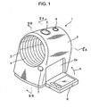
- FIG. 1 A blood pressure monitor according to an embodiment of the present invention is shown in FIG. 1 .
- This blood pressure monitor 1 has a compact and simple construction for home use, wherein a box-shaped housing 2 is formed with an arm inserting hole 3 penetrating the housing 2 along forward and backward directions and a soft tubular cuff ring 4 into which an arm is inserted is arranged in the arm inserting hole 3.
- the cuff ring 4 is made of a fabric of a polyethylene or the like.
- a start/end switch 5 and an emergent exhaust switch 6 are provided at the top of the housing 2, an opening button 7 for opening a display panel 8 is provided at the front side, and the display panel 8 openable and closable by a hinge is provided at a side.
- the display panel 8 Upon being closed in a direction of arrow "a" from an open position shown in FIG. 1 , the display panel 8 is accommodated and locked at a closed position by being fitted into a recess 2a formed in a side surface of the housing 2.
- the opening button 7 is pushed, the display panel 8 is unlocked and can be opened to the open position.
- a pump, an exhaust valve, a pressure sensor and the like are provided in the housing 2 and connected by a pipe for supplying an air to a blood flow blocking bag 11 to be described later, and have operation timings thereof controlled by a control unit.
- an arm rest 10 substantially T-shaped in front view is provided below the arm inserting hole 3 of the housing 2, wherein the upper surface of this arm rest 10 is formed into a curve in conformity with a curvature of the arm inserting hole 3.
- This arm rest 10 is a hard molded article made of, for example, an ABS resin.
- a cuff 12 holding the blood flow blocking bag 11 is arranged at an upper part and opposite end portions 12a thereof are coupled to a take-up drum 13 provided at a bottom part of the housing 2 by way of the opposite sides of the arm rest 10.
- the cuff 12 is, for example, a flexible plastic sheet, and a portion thereof holding the blood flow blocking bag 11 serves also as a clip board for suppressing the inflation of the blood flow blocking bag 11.
- the take-up drum 13 is driven in forward and backward directions by an electric motor having a commercially available dry battery 16 set in the housing 2 as a power supply.
- the take-up drum 13 is rotated in a direction of arrow "b" to take up the cuff 12 upon being driven in forward direction while being rotated in a direction of arrow "c” to rewind the cuff 12 upon being driven in reverse direction.
- the cuff ring 4 is arranged between the arm rest 10 and the cuff 12 with an insertion-side ring portion 4a engaged with an arm entrance 3a of the arm inserting hole 3 and an exit-side ring portion 4b engaged with an arm exit 3b of the arm inserting hole 3, thereby covering the inner circumferential surface of the arm inserting hole 3.
- a flexible auxiliary sheet 14 having a rectangular shape longer along circumferential direction than the upper surface of the arm rest 10 may be so mounted on a lower part of the outer surface of the cuff ring 4, for example, by adhesive as to face the upper surface of the arm rest 10.
- a pulse wave of the artery is extracted by a filter or the like when the arm is pressed by the blood flow blocking bag 11, and a blood pressure value is calculated using a specified algorithm and the result is displayed on the display panel 8.
- the cuff 12 is not rectangle-shaped as shown in phantom line "d", but is shaped such that opposite longitudinal end portions 12a' of the cuff 12 are inclined as shown in solid line. Opposite side portions 12b, 12c in the middle having opposite widthwise end portions 12d of the cuff 12 are so shaped as to extend along a direction normal to the longitudinal axis of the drum 13. In other words, the cuff 12 appears to be fan-shaped.
- the inclined opposite end portions 12a' of the cuff 12 are coupled to the take-up drum 13 in parallel with a longitudinal direction "e" of the take-up drum 13 with the end edges thereof put together aligned.
- the cuff 12 When being taken up by rotating the take-up drum 13 having the inclined opposite end portions 12a' of the cuff 12 coupled thereto in a direction of arrow "b", the cuff 12 is wound substantially into the shape of a conical tube larger at the outer end portion 12b and smaller at the inner end portion 12c since the entire length of the outer end portion 12b is longer than that of the inner end portion 12c.
- the opposite longitudinal end portions 12d in the middle of the cuff 12 are so shaped as to extend along the direction normal to the longitudinal direction of the take-up drum 13, this can prevent the cuff 12 from being taken up while being displaced along the longitudinal direction of the take-up drum 13 when the cuff 12 is taken up by the take-up drum 13.
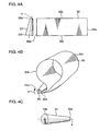
- FIGS. 4A to 4C show a modification of the cuff used in this embodiment.
- a modified cuff 32 is rectangle-shaped, the take-up drum 33 is formed to have a conical shape and opposite end portions 32a of the cuff 32 are coupled in parallel to the conical surface of the take-up drum 33.
- this cuff 32 is provided with the blood flow blocking bag 11 at an upper side and is made of a flexible plastic sheet.
- the cuff 32 When being taken up by rotating the conically shaped take-up drum 33 having the opposite end portions 32a of the cuff 32 coupled thereto in a direction of arrow "b", the cuff 32 is wound substantially into such a conical tube larger at a widthwise end portion 32b at a thinner side 33a of the drum and smaller at a widthwise end portion 32c at a thicker side 33b since the thinner side 33a of the take-up drum 33 has a shorter circumference than the thicker side 33b.
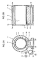
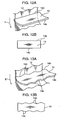
- FIGS. 5A and 5B show a modification of the cuff used in this embodiment.
- a modified cuff 42 is rectangle-shaped, V-shaped slits or cuts 42e extending toward an other widthwise end portion 42c are formed at specified intervals along longitudinal direction at one widthwise end portion 42b of the cuff 42. Similar to the cuff 12, this cuff 42 is provided with the blood flow blocking bag 11 at an upper side and is made of a flexible plastic sheet.
- the cuff 42 When being taken up by rotating a take-up drum 43 having opposite end portions 42a of the cuff 42 coupled thereto in a direction of arrow "b", the cuff 42 can be wound substantially into such a conical tube larger at the widthwise end portion 42b formed with the slits 42e and smaller at the widthwise end portion 42c having no slit 42e since the widthwise end portion 42b formed with the slits 42e has a better stretchability or elongation than the widthwise end portion 43c having no slit 42e.
- the thicker side D1 of the upper arm M1 is placed at the end portion 42b having the slits 42e and the thinner side D2 is placed at the end portion 42c having no slit 42e similar to the state shown in FIG. 3C , there is no clearance between the cuff 42 and the upper arm M1 and, hence, the upper arm M1 can be evenly pressed by the blood flow blocking bag 11. Therefore, measurement precision can be improved. Further, an inexpensive production cost can be realized since the arm can be evenly pressed only by forming the cuff 42 with the slits 42e.
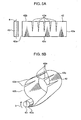
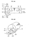
- FIGS. 6A and 6B show another modification of the cuff used in this embodiment.
- a modified cuff 52 is rectangle-shaped, a slit 52f is formed in each end portion 52a to divide this end portion 52a into two sections along widthwise direction, two take-up drums 53A, 53B are provided and constructed to independently take up the cuff 52 via clutches 16A, 16B and electric motors 17A, 17B, and divided end portions 52a-1 and 52a-2 of the cuff 52 are respectively coupled to the take-up drums 53A, 53B at the same sides. Similar to the cuff 12, this cuff 52 is provided with the blood flow blocking bag 11 at an upper side and is made of a flexible plastic sheet.
- the cuff 52 When the cuff 52 is taken up by rotating the take-up drums 53A, 53B coupled to the corresponding end portions 52a-1, 52a-2 of the cuff 52 divided into two sections in a direction of arrow "b" via the clutches 16A, 16B and the electric motors 17A, 17B, the divided end portions 52a-1, 52a-2 of the cuff 52 are independently wound by the take-up drums 53A, 53B.
- the cuff 52 can be wound substantially into a conical tube similar to the state shown in FIG. 3C by letting the take-up drum 53A at the thinner side of the upper arm M1 continue to take up the cuff 52 even if a load acting on the take-up drum 53B corresponding to the end portions 52a-2 at the thicker side D1 of the upper arm M1 increases to turn the clutch 16B off, thereby stopping taking up the cuff 52.
- the take-up drum 53A at the thinner side of the upper arm M1 continue to take up the cuff 52 even if a load acting on the take-up drum 53B corresponding to the end portions 52a-2 at the thicker side D1 of the upper arm M1 increases to turn the clutch 16B off, thereby stopping taking up the cuff 52.
- the upper arm M1 can be evenly pressed by the blood flow blocking bag 11. Therefore, measurement precision can be improved.
- a wrist M2 can be used as a measurement part.
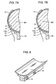
- FIGS. 7A and 7B show a mounted state of the auxiliary sheet 14.
- the cuff ring 4 is arranged between the arm rest 10 and the cuff 12 and covers the inner circumferential surface of the arm inserting hole 3 by being engaged with the arm entrance 3a and the arm exit 3b.
- the auxiliary sheet 14 is mounted to the cuff ring 4 as shown in FIG. 9 by an adhesive or the like.
- the auxiliary sheet 14 is mounted at such a position as to face the upper surface of the arm rest 10.
- the width (i.e., length along the circumferential direction of the cuff ring 4) of the auxiliary sheet 14 is larger than the width (i.e., length along the circumferential direction of the cuff ring 4) of the upper surface of the arm rest 10.
- the auxiliary sheet 14 is preferably a PET (polyethylene terephthalate) sheet having a thickness of about 0.5 mm, but may be a metallic sheet having a spring property. It should be noted that the auxiliary sheet 14 may be mounted on the upper surface of the arm rest 10 by an adhesive or screws as shown in FIG. 8 .
- the flexible auxiliary sheet 14 longer along circumferential direction than the arm rest 10 is pressed against the cuff 12 whose width is narrowed as the cuff 12 is taken up, whereby opposite end portions 14a along the circumferential direction rise (see arrow "g") to cover the opposite sides of the arm M1, M2 inserted into the cuff ring 4.
- This can prevent the epidermis part of the arm M1, M2 from being pulled by the cuff 12 being taken up to get in between the cuff ring 4 and the lateral portions of the arm rest 10.
- FIG. 7A shows an example of the thicker arm M1 and FIG. 7B shows an example of the thinner arm M2. Since the opposite end portions 14a of the auxiliary sheet 14 fit and rise along the arm M1, M2 regardless of the thicker arm M1 or the thinner arm M2, the epidermis part does not get caught up in either case.
- auxiliary sheet 14 is adhered to the outer surface of the cuff ring 4 in the foregoing embodiment, a bag-shaped accommodating portion or pocket 15 stitched at three sides may be provided on the outer surface of the cuff ring 4 and the auxiliary sheet 14 may be inserted and accommodated into this bag-shaped accommodating portion 15. In such a case, an entrance portion is stitched at points to prevent the auxiliary sheet 14 from coming out after the auxiliary sheet 14 is accommodated into the bag-shaped accommodating portion 15.
- auxiliary sheet 14 is accommodated into the bag-shaped accommodating portion 15 of the cuff ring 4 in this way, problems that the auxiliary sheet 14 comes out of the cuff ring 4 and the mounted position of the auxiliary sheet 14 is displaced are less likely to occur as compared to a case where the auxiliary sheet 14 is adhered.
- auxiliary sheet 14 is placed on the outer surface of the cuff ring 4, a sheet 18 is placed on the auxiliary sheet 14 and the cuff ring 4 and the sheet 18 are stitched "f" along the outer contour of the auxiliary sheet 14 as shown in FIGS. 11A and 11B , there is no likelihood of displacing the mounted position of the auxiliary sheet 14.
- the auxiliary sheet 14 can be directly stitched with the cuff ring 4 by placing the auxiliary sheet 14 on the outer surface of the cuff ring 4.
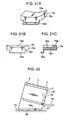
- auxiliary sheet 14 is rectangular and edges 14b toward the cuff 12 are formed to be straight as shown in FIGS. 12A and 12B , the edges 14b of the auxiliary sheet 14 are entirely in contact with the cuff 12 being taken up in a direction of arrow "h". Thus, a winding resistance of the cuff 12 increases.
- the winding resistance can be considerably reduced by forming projected and recessed portion portions 14c in plan view at the edges 14b of the auxiliary sheet 14 toward the cuff 12 as shown in FIGS. 13A, 13B .
- the winding resistance of the cuff 12 can decrease to suppress the consumption of an electric power of a dry battery used for the electric motor (not shown) for driving the take-up drum 13.
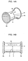
- the cuff ring 4 is made of a stretch material stretchable at least along longitudinal direction W. This does not mean, however, that the cuff ring 4 may not be stretchable along circumferential direction R.
- the stretch material is preferably stretchable both along longitudinal direction W and circumferential direction R, but is sufficient if it is stretchable at least along longitudinal direction W in view of a material cost. With such a construction of the cuff ring 4, the winding resistance can be reduced.
- the stretch material may be the one made of synthetic fibers such as spandex fibers or the one rendered to have stretchability by applying a heating treatment after weaving. Either one may be used.
- a stretch material having a stretch ratio of 2 at a load of 100 g may be suitably used.
- the cuff ring 4 Since having a large stretch ratio at least along longitudinal direction, the cuff ring 4 is likely to considerably elongate along longitudinal direction W as shown in phantom line "d" in FIG. 14B when the cuff ring 4 has its diameter reduced by the cuff 12 at the time of taking up the cuff 12. Since resistance is remarkably reduced during this elongation, the consumption of the electric power by the electric motor 17 for driving the take-up drum 13 can be suppressed. Further, the cuff ring 4 contracts to return to its initial shape at the time of increasing the diameter of the cuff 12, its appearance is better.
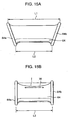
- FIGS. 15A, 15B show a modification of the cuff ring.
- This modified cuff ring 64 is such that length L1 of the upper side of the cuff ring 64 where the blood flow blocking bag 11 is provided is set to be longer than length L2 of the lower side as shown in FIG. 15A , and the longer upper side having the length L1 is loosened as shown in solid line "j" in FIG. 15B when the cuff ring 64 is assembled into the housing 2.
- the cuff ring 64 is likely to be considerably loosened along longitudinal direction W as shown in solid line "j" in FIG.
- the cuff ring 64 made of the same material as the conventional one being soft, but hardly stretchable can also be used.
- an embossed portion 19a (crosshatched portion) is entirely or partly formed on the surface of each sliding contact portion 2d.
- the embossed portion 19a is minute projections and recesses or unevenness formed on the outer surface of each sliding contact portion 2d, wherefore the cuff 12 is in contact only with the projections.
- ribbed portions 19b may be entirely or partly formed on the surface of each sliding contact portion 2d. By forming the ribbed portions 19b, the cuff 12 is in contact only with the projected portions or ribs. Alternatively, tapes having a good lubricating property may be adhered to serve as portions treated to better the slidability thereof.
- FIG. 17A shows the construction of a connecting tube 20 for supplying an air to the blood flow blocking bag 11 of the cuff 12.
- the connecting tube 20 connects the blood flow blocking bag 11 and the pump.
- a portion of this connecting tube 20 connected with the blood flow blocking bag 11 is formed with an extensible portion 20a curved in U-shape.
- the portion of this connecting tube 20 connected with the blood flow blocking bag 11 may be formed with an extensible portion 20b wound in a spiral manner.
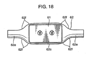
- FIG. 18 shows a modified cuff 62 improved in view of the winding resistance.
- Chamfered portions 62f are formed on portions of the cuff 62 coupling the four corners of a blood flow blocking bag holding portion 62c and take-up portions 62e. Since a sliding resistance caused by the cuff 62 getting caught decreases by forming the chamfered portions 62e, the consumption of the electric power of the electric motor 17 for driving the take-up drum 13 can be suppressed.
- the aforementioned constructions for reducing the winding resistance may be singly used or may be used in a suitable combination.
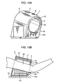
- FIG. 19A is a perspective view showing the entire construction of this modification.
- the cuff ring 4 is not shown in order to clearly show the internal construction.
- an elbow support 78 is provided below the arm exit 3b on an exit-side wall 72a of the housing 2.
- the elbow support 78 projects from the exit-side wall 72a for placing an elbow 77 of the arm M inserted into the arm inserting hole 3.
- elbow support 78 does not take up much space because it is sufficient to provide it near the arm exit 3b of the arm inserting hole 3 of the housing 2.
- an inserting angle of the arm M and the center of the arm inserting hole 3 may not agree depending on the height of the table 79 or the like, whereby the cuff 4 cannot be correctly wound around the arm M.
- a lower part of the housing 2 at the side of the arm exit 3b of the arm inserting hole 3 is supported on a base 80 of the blood pressure monitor 1 via a hinge member 81 to install the housing 2 rotatably toward an arm exit side (see arrow "k").
- the housing 2 is rotated toward the arm exit side by the weight of the elbow 77, whereby the inserting angle of the arm M comes to agree with the center of the arm inserting hole 3.
- the cuff 4 can be correctly wound around the arm M, thereby improving reliability in measurement precision.
- the housing 2 and the base 80 can be installed rotatably toward the arm exit side (see arrow "k") by fixing the housing 2 and the base 80 to each other and supporting the base 80 on the table 79 or the like via the hinge member 81.
- an elbow placing surface 78a is formed into a concave surface along transverse direction as shown in FIG. 21A , the elbow support 78 can be prevented from making transverse displacements when the elbow 77 is placed on the elbow support 78.
- a stable blood pressure measurement can be constantly carried out to reduce a variation in measurement precision.
- a raised surface 78b may be formed at the arm exit side of the elbow placing surface 78a of the elbow support 78. Then, the placing position of the elbow 77 can be recognized by the feeling when the elbow 77 is placed on the elbow support 78, whereby displacements of the elbow 77 in arm exiting direction can be prevented. Thus, a stable blood pressure measurement can be constantly carried out to reduce a variation in measurement precision.
- the elbow support 78 is made of a soft material (e.g., a rubber material having a hardness of about 70 to 90), pain the elbow 77 possibly has upon being placed on the elbow support 78 can be mitigated.
- a soft material e.g., a rubber material having a hardness of about 70 to 90
- an elbow placing portion 78c of the elbow support 78 is made of a soft material and a mounting portion 78d to the housing 2 is made of a hard material (e.g., a hard synthetic resin or a metal), the pain the elbow 77 possibly has upon being placed on the elbow support 78 can be mitigated and, simultaneously, a sufficient mounting force to the housing 2 can be ensured.
- a hard material e.g., a hard synthetic resin or a metal
- the elbow support 78 may be formed by an inflatable and contractible air bag. With such a construction, the pain the elbow 77 possibly has upon being placed on the elbow support 78 made of the air bag can be mitigated and the elbow support 78 can be accommodated in a compact manner by letting the air bag contact.
- this construction is inexpensive because the air supplying pump and the air exhaust valve for the blood flow blocking bag built in the blood pressure monitor 1 can be used as means for supplying and discharging the air to and from the air bag to inflate and contact the air bag.
- the elbow support 78 is vertically pivotally supported at a position below the arm exit 3b of the arm inserting hole 3 via the hinge member 81 as shown in FIG. 22 , the elbow support 78 can be folded toward the housing 2 when being not used (see phantom line). Thus, the elbow support 78 can be accommodated into the arm inserting hole 3 in a compact manner.
- a lower arm support 82 for placing a lower arm M2 is so provided as to be continuous with the elbow support 78 as shown in FIG. 23A , the arm can be entirely supported. Thus, the posture of the entire arm can be stabilized during the measurement.
- the lower arm support 82 can be folded toward the housing 2 together with the elbow support 78 as shown in FIG. 23B .
- the used lower arm support 82 whose sections are connected like a chain has such a construction that it can be bent at the respective joints with respect to a folding direction, but cannot be bent by the engagement of stoppers of the respective joints with respect to an extending direction.
- the lower arm support 82 used may be an extensible rod.
- a grip 82a that can be gripped by a hand M3 is provided at the leading end of the lower arm support 82 as shown in FIGS. 23A and 24B , the palm (side of veins whose flow is desired to be blocked) of the hand M3 naturally faces up. Thus, blood pressure can be precisely measured.
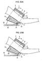
- a bone portion 77a projecting from the elbow 77(R) is located at an inner side when the elbow 77(R) of the right arm is seen from front.
- a bone portion 77a projecting from the elbow 77(L) is located at an inner side when the elbow 77(L) of the left arm is seen from front. Accordingly, if the elbow placing surface 78a of the elbow support 78 is flat, the position of the elbow 77(R, L) cannot be stably fixed due to the projecting bone portion 77a.
- a recess 78e in conformity with the bone portion 77a of the elbow 77(R) of the right arm may be formed in the elbow placing surface 78a of the elbow support 78 as shown in FIG. 25A .
- a recess 78f in conformity with the bone portion 77a of the elbow 77(R) of the left arm may be formed in the elbow placing surface 78a of the elbow support 78 as shown in FIG. 25B .
- the recesses 78e, 78f in conformity with the bone portions of the elbows 77(L, R) of the left and right arms are formed in the elbow placing surface 78a of the elbow support 78 as shown in FIG. 25C .
- the bone portion 77a conforms to the recess 78e to stably fix the position of the elbow 77(R) if the elbow 77(R) of the right arm is placed on the elbow placing surface 78a of the elbow support 78 as shown in FIG.
- the elbow support 78 is made of an urethane having a low elasticity, the elbow support 78 fits the elbow 77(L, R) regardless of the shapes of the elbows 77(L, R) of the left and right arms even if the recesses 78e, 78f as above are not formed in the elbow placing surface 78a of the elbow support 78. Therefore, the position of the elbow can be stably fixed.
- a rising portion 78c that is so supported via a hinge portion 78b as to be vertically pivotal (see arrow "D") and can rise any time may be provided at the leading end of the elbow support 78.
- a leaf spring 83 for biasing the rising portion 78c in rising direction is embedded in the elbow support 78 and the rising portion 78c by insert molding.
- the measurer can insert the arm into the arm inserting hole 3 to place the elbow 77 of the bent arm on the rising portion 78c, thereby positioning the elbow 77. If the elbow 77 is stretched thereafter as shown in FIG. 26B , the rising portion 78c lays down straight against a biasing force of the leaf spring 83, wherefore the elbow 77 does not come into contact with the rising portion 78c and a possible pain at the elbow 77 can be reduced.
- the position of the arm M on the elbow support 78 with respect to inserting direction can be adjusted (see arrow "p") by forming an internally threaded portion 2c in a side wall 2b of the rear part of the housing 2 below the arm exit 3b of the arm inserting hole 3 and mounting a male screw 78g engageable with the internally threaded portion 2c on the elbow support 78 to change the engaged position of the male screw 2c.
- a click-stop construction or the like can be adopted. Accordingly, even if measurers whose arms M differ in length use this blood pressure monitor, the elbows 77 can be placed at proper positions.
- the elbow support 78 is so supported between the vicinity of the entrance of the arm inserting hole 3 and the vicinity of the exit thereof as to be movable along forward and backward directions, the arm M can be inserted into the arm inserting hole 3 together with the elbow support 78 with the elbow support 78 brought closer to the entrance of the arm inserting hole 3 and the elbow 77 placed on the elbow support 78.
- the elbow placing position is easy to see and, therefore, problems of excessively or insufficiently inserting the arm M into the arm inserting hole 3 can be solved.
- the housing 2 is so supported on the base 80 as to be movable along the inserting direction of the arm and the elbow support 78 is mounted at a part of the base 80 corresponding to the vicinity of the entrance of the arm inserting hole 3 of the housing 2, the arm M can be inserted into the arm inserting hole 3 together with the elbow support 78 by moving the housing 2 with the elbow 77 placed on the elbow support 78.
- the elbow placing position is easy to see and, therefore, problems of excessively or insufficiently inserting the arm M into the arm inserting hole 3 can be solved.
- the measurer can carry out a measurement in a natural posture without bending forward.
- a detector e.g., switch or the like
- notification can be made by giving a notification sound or the like when the detector detects that the measurer has placed the elbow 77 on the elbow support 78.
- the measurer can recognize that the elbow 77 is placed at a suitable position and can carry out a measurement while feeling at ease. Further, an automatic measurement is possible by starting automatically taking up the cuff 12 and the like upon the detection by the detector.
- an inventive blood pressure monitor is provided with a box-shaped housing having openings formed in left and right side walls; a cuff transversely arranged in the housing, including an arm entrance and an arm exit at the opposite left and right ends corresponding to the openings and having a blood flow blocking bag formed in a specified area; a cuff take-up drum for taking up the opposite ends of the cuff so that the blood flow blocking bag extends along an outer circumferential surface of the inserted arm at the time of a measurement; and a pump for supplying the compressed air to the blood flow blocking bag.
- the fastening force adjusting construction preferably includes a cylindrical take-up drum, and the cuff having, in its development, one longitudinal end thereof inclined in a first direction and having the other longitudinal end thereof inclined in a second direction intersecting with the first direction at a specified angle.
- the outward facing widthwise end of the cuff becomes longer while the inward facing widthwise end thereof becomes shorter when the drum having the opposite longitudinal ends of the cuff coupled thereto is rotated to take up the cuff. Accordingly, the cuff is wound substantially into a conical tube thicker at the outward facing end and thinner at the inward facing end. If the thicker side of the arm or the like is positioned at the outward facing end and the thinner side thereof is positioned at the inward facing side, there is no clearance between the cuff and the arm or the like. Thus, the arm or the like can be evenly pressed by the blood flow blocking bag, thereby improving the measurement precision. Further, it is inexpensive because the measurement part can be evenly pressed only by changing the outer shape of the cuff.
- the first direction preferably intersects with the longitudinal axis of the take-up drum at right angles. This can prevent the cuff from being taken up while being displaced along the longitudinal direction of the drum when the cuff is wound onto the drum.
- the fastening force adjusting construction may include a cuff rectangular in its development and a conical take-up drum.
- the conical drum having the opposite ends of the cuff coupled thereto is rotated to take up the cuff, the cuff is wound substantially into a conical tube ticker at one widthwise end of the cuff corresponding to the thinner side of the drum and thinner at the other widthwise end thereof corresponding to the thicker side of the drum. Accordingly, if the thicker side of the arm or the like is positioned at the thinner side of the drum and the thinner side thereof is positioned at the thicker side of the drum, there is no clearance between the cuff and the arm or the like. Thus, the arm or the like can be evenly pressed by the blood flow blocking bag, thereby improving the measurement precision. Further, it is inexpensive because the measurement part can be evenly pressed only by changing the shape of the drum.
- the fastening force adjusting construction preferably includes a cuff having a specified number of slits formed at the side corresponding to the arm entrance side.
- the cuff can be wound substantially into a conical tube thicker at the side having the slits and thinner at the side having no slit since one widthwise end of the cuff having the slits has a better stretchability along longitudinal direction than the other widthwise end of the cuff having no slit.
- the thicker side of the arm or the like is positioned at the end of the cuff having the slits and the thinner side thereof is positioned at the end of the cuff having no slit, there is no clearance between the cuff and the arm or the like.
- the arm or the like can be evenly pressed by the blood flow blocking bag, thereby improving the measurement precision. Further, it is inexpensive because the measurement part can be evenly pressed only by forming the slits in the cuff.
- the fastening force adjusting construction preferably includes a cuff having the opposite ends split into an arm entrance side and an arm exit side, and two take-up drums for independently taking up the end of the cuff at the arm entrance side and the end of the cuff at the arm exit side.
- the drums coupled to the corresponding ends of the cuff split into two sections are rotated to take up the cuff, the opposite ends of the cuff split into two sections can be independently wound.
- the cuff can be wound substantially into a conical tube by continuing to take up the cuff by means of the drum at the thinner side of the arm or the like by the drum even after the take-up of the cuff by the drum at the thicker side of the arm or the like is stopped, there is no clearance between the cuff and the arm or the like.
- the arm or the like can be evenly pressed by the blood flow blocking bag, thereby improving the measurement precision.
- a cuff ring in the form of a cylindrical tube transversely arranged inside the cuff and having an arm entrance and an arm exit at the opposite left and right ends communicating with the openings and made of a soft material, and an arm rest disposed below the cuff ring, and to mount a flexible auxiliary sheet longer along circumferential direction than the arm rest on the cuff ring or the arm rest.
- the auxiliary sheet longer along circumferential direction than the arm rest is pressed against the cuff whose width becomes narrower as the cuff is taken up, whereby the opposite ends of the auxiliary sheet with respect to circumferential direction rise to cover the opposite sides of the arm inserted into the cuff ring.
- This can prevent the epidermis part of the arm from being pulled by the cuff being taken up to get in between the cuff ring and the lateral portions of the arm rest.
- a cuff ring with a bag-shaped accommodating portion and accommodate the auxiliary sheet in the bag-shaped accommodating portion. Since the auxiliary sheet is accommodated into the bag-shaped accommodating portion of the cuff ring, problems that the auxiliary sheet comes out of the cuff ring and the mount position thereof is displaced do not occur.
- a resistance reducing construction for reducing resistance at the time of taking up the cuff by the cuff take-up drum may be provided. Since resistance at the time of taking up and rewinding the cuff is reduced by the resistance reducing construction, the consumption of the electric power can be suppressed in such a case where an electric battery is used as a power supply for a motor or the like for driving the automatic take-up mechanism.
- the resistance reducing construction may include a cuff ring in the form of a cylindrical tube transversely arranged inside the cuff, having an arm entrance and an arm exit at the opposite left and right ends communicating with the openings, and made of a stretch material stretchable at least along transverse direction. Since the cuff ring largely stretches at least along its longitudinal direction, the resistance of the cuff ring decreases upon reducing the diameter of the cuff ring by the cuff at the time of taking up the cuff. Thus, the consumption of the electric power of the automatic take-up drum can be suppressed.
- the resistance reducing construction may include a cuff ring transversely arranged inside the cuff, having an arm entrance and an arm exit at the opposite left and right ends communicating with the openings and having the side thereof toward the blood flow blocking bag loosened. Since the side of the cuff ring toward the blood flow blocking bag is largely loosened, the resistance of the cuff ring decreases upon reducing the diameter of the cuff ring by the cuff at the time of taking up the cuff. Thus, the consumption of the electric power of the automatic take-up drum can be suppressed.
- the resistance reducer may be realized by forming sliding portions treated to better the slidability in the sliding contact portions of the housing with which the cuff comes into sliding contact. Since the contact resistance of the cuff is reduced by the sliding portions, the consumption of the electric power of the automatic take-up drum can be suppressed.
- the resistance reducer may include an extensible portion formed in the connecting tube connecting the blood flow blocking bag and the pump. Since the tensile resistance of the connecting tube at the time of taking up and rewinding the cuff decreases due to the elongation and construction of the extensible portion, the consumption of the electric power of the automatic take-up drum can be suppressed.
- the resistance reducer may be realized by chamfering the portions of the cuff coupling the blood flow blocking bag and the take-up ends. Since the sliding resistance of the cuff created upon getting caught is reduced by the chamfered portions, the consumption of the electric power of the automatic take-up drum can be suppressed.
- an elbow support for supporting the elbow of the inserted arm near the arm exit.
- how much the upper arm should be inserted into the arm inserting hole can be known when the measurer inserts the upper arm into the arm inserting hole. This enables blood pressure measurements to be constantly carried out at the fixed measurement position, thereby improving the reliability in measurement precision.
- the elbow support since it is sufficient to provide the elbow support only near the exit of the arm inserting hole of an arm insertion block, the elbow support may be provided in a compact manner.
- the base for supporting the housing rotatably toward the arm exit side may be coupled to the part of the housing below the arm exit via the hinge member.
- the elbow support may be formed such that the elbow placing surface is a curved surface concave in section along widthwise direction. Since the elbow placing surface of the elbow support is formed into the curved surface concave in section along widthwise direction, lateral displacements of the elbow can be prevented when the elbow is placed on the elbow support. Thus, stable blood pressure measurements can be constantly carried out to reduce a variation in measurement precision.
- the elbow support may be formed with a raised portion at the projecting end thereof. This enables the recognition of the elbow placing position by the feeling, thereby preventing displacements of the elbow in projecting direction. Thus, stable blood pressure measurements can be constantly carried out to reduce a variation in measurement precision.
- the elbow support may be foldable toward the housing. Since the elbow support can be folded toward the arm insertion block, it can be accommodated at the side of the arm insertion block in a compact manner.
- the lower arm supporting member for supporting the lower arm may be so provided as to be continuous with the elbow support and may be foldable toward the housing together with the housing. With this construction, the entire arm can be held in a stable posture during the measurement since it can be supported. Further, since the lower arm support can be folded toward the housing together with the elbow support, the elbow support and the lower arm support can be accommodated at the side of the arm insertion block in a compact manner.
- the elbow placing surface of the elbow support may be formed with recesses in conformity with the bone of the elbow. This enables the position of the elbow to be stably fixed regardless of which of the left and right elbows is placed on the elbow support.
Landscapes
- Health & Medical Sciences (AREA)
- Life Sciences & Earth Sciences (AREA)
- Cardiology (AREA)
- Vascular Medicine (AREA)
- Engineering & Computer Science (AREA)
- Medical Informatics (AREA)
- Physics & Mathematics (AREA)
- Ophthalmology & Optometry (AREA)
- Biophysics (AREA)
- Pathology (AREA)
- Veterinary Medicine (AREA)
- Biomedical Technology (AREA)
- Heart & Thoracic Surgery (AREA)
- Physiology (AREA)
- Molecular Biology (AREA)
- Surgery (AREA)
- Animal Behavior & Ethology (AREA)
- General Health & Medical Sciences (AREA)
- Public Health (AREA)
- Dentistry (AREA)
- Measuring Pulse, Heart Rate, Blood Pressure Or Blood Flow (AREA)
Claims (8)
- Blutdruckmonitor (1), umfassend:ein kastenförmiges Gehäuse (2) mit Öffnungen, die in einer linken und einer rechten Seitenwand gebildet sind;eine Manschette (12, 32, 42, 52), die quer in dem Gehäuse (2) angeordnet ist und einen Armeingang (3a) und einen Armausgang (3b) an den gegenüberliegenden bzw. entgegengesetzten linken und rechten Enden entsprechend der Öffnungen enthält und die einen Blutflussblockierbeutel (11) aufweist, der in einem bestimmten Bereich gebildet ist;eine Manschettenaufnahmetrommel (13, 33, 43, 53A, 53B) zum Aufnehmen der Manschette (12, 32, 42, 52); undeine Pumpe zum Zuführen von Druckluft an den Blutflussblockierbeutel (11);dadurch gekennzeichnet, dassdie Manschettenaufnahmetrommel (13, 33, 43, 53A, 53B) die beiden gegenüberliegenden bzw. entgegengesetzten Endabschnitte (12a, 32a, 42a, 52a) der Manschette (12, 32, 42, 52) aufnimmt, so dass sich der Blutflussblockierbeutel (11) zum Zeitpunkt einer Messung entlang der äußeren Umfangsfläche bzw. -oberfläche des eingeführten Arms erstreckt.
- Blutdruckmonitor (1) nach Anspruch 1, ferner umfassend eine Befestigungskrafteinstellkonstruktion zum Ausgleichen bzw. gleichmäßigen Verteilen einer Armbefestigungskraft an Teilen der Manschette (12, 32, 42, 52) an einer Armeingangsseite und an einer Armausgangsseite.
- Blutdruckmonitor (1) nach Anspruch 2, wobei die Befestigungskrafteinstellkonstruktion eine zylindrische Aufnahmetrommel (13) und eine Manschette (12) enthält, von der ein Längsende (12') in einer ersten Richtung geneigt ist und das andere Längsende (12') in einer zweiten Richtung geneigt ist, die sich mit der ersten Richtung in einem bestimmten Winkel in bzw. während ihrer Entwicklung schneidet.
- Blutdruckmonitor (1) nach einem der vorhergehenden Ansprüche, ferner umfassend:einen Manschettenring (4, 64) in der Form eines zylindrischen Schlauchs, der quer innerhalb der Manschette (12, 32, 42, 54) angeordnet ist und einen Armeingang (3a) und einen Armausgang (3b) an den gegenüberliegenden bzw. entgegengesetzten linken und rechten Enden aufweist, die mit den Öffnungen kommunizieren bzw. in Verbindung stehen, und der aus einem weichen Material besteht;eine Armablage (10), die an einem unteren Teil des Manschettenrings (4, 64) angeordnet ist; undeine flexible Hilfsplatte bzw. -schale (14), die an dem Manschettenring (4, 64) oder der Armablage (10) montiert ist und entlang einer Umfangsrichtung länger ist als die Armablage (10).
- Blutdruckmonitor (1) nach einem der vorhergehenden Ansprüche, ferner umfassend eine Widerstandsreduzierungskonstruktion zum Reduzieren eines Widerstands zum Zeitpunkt des Aufnehmens der Manschette (12, 32, 42, 52) durch die Manschettenaufnahmetrommel (13, 33, 43, 53A, 53B).
- Blutdruckmonitor (1) nach einem der vorhergehenden Ansprüche, ferner umfassend eine Ellenbogenstütze (78), die nahe des Armausgangs vorgesehen ist, um den Ellenbogen (77) des eingeführten Arms zu stützen.
- Blutdruckmonitor (1) nach einem der vorhergehenden Ansprüche, ferner umfassend eine Basis (80), die über ein Gelenkglied an einen unteren Teil der Armausgangsseite des Gehäuses (2) gekoppelt ist und angepasst ist, das Gehäuse (2) zu der Armausgangsseite hin schwenkbar zu stützen.
- Blutdruckmonitor (1) nach einem der vorhergehenden Ansprüche, wobei die Ellenbogenstütze (78) zu dem Gehäuse (2) hin gefaltet bzw. gebogen bzw. geklappt werden kann.
Applications Claiming Priority (8)
| Application Number | Priority Date | Filing Date | Title |
|---|---|---|---|
| JP2004047512 | 2004-02-24 | ||
| JP2004047551 | 2004-02-24 | ||
| JP2004047512A JP4186839B2 (ja) | 2004-02-24 | 2004-02-24 | 血圧計 |
| JP2004047492 | 2004-02-24 | ||
| JP2004047551A JP4148155B2 (ja) | 2004-02-24 | 2004-02-24 | 血圧計 |
| JP2004047492A JP4151586B2 (ja) | 2004-02-24 | 2004-02-24 | 血圧計 |
| JP2004154565A JP4453441B2 (ja) | 2004-05-25 | 2004-05-25 | 血圧計 |
| JP2004154565 | 2004-05-25 |
Publications (2)
| Publication Number | Publication Date |
|---|---|
| EP1568315A1 EP1568315A1 (de) | 2005-08-31 |
| EP1568315B1 true EP1568315B1 (de) | 2009-11-25 |
Family
ID=34753822
Family Applications (1)
| Application Number | Title | Priority Date | Filing Date |
|---|---|---|---|
| EP05004076A Ceased EP1568315B1 (de) | 2004-02-24 | 2005-02-24 | Blutdruckmonitor |
Country Status (6)
| Country | Link |
|---|---|
| US (1) | US7207944B2 (de) |
| EP (1) | EP1568315B1 (de) |
| KR (1) | KR100679972B1 (de) |
| CN (1) | CN100411582C (de) |
| DE (1) | DE602005017840D1 (de) |
| TW (1) | TWI278304B (de) |
Families Citing this family (37)
| Publication number | Priority date | Publication date | Assignee | Title |
|---|---|---|---|---|
| USD537946S1 (en) * | 2004-06-02 | 2007-03-06 | Matsushita Electric Works, Ltd. | Blood pressure monitor |
| JP2006000337A (ja) * | 2004-06-17 | 2006-01-05 | Omron Healthcare Co Ltd | 電子血圧計 |
| JP4595449B2 (ja) * | 2004-09-02 | 2010-12-08 | オムロンヘルスケア株式会社 | 血圧計用カフ |
| US20060184053A1 (en) * | 2005-02-15 | 2006-08-17 | Health & Life Co., Ltd. | Tunnel type sphygmomanometer assembly |
| US20070106166A1 (en) * | 2005-10-12 | 2007-05-10 | Somberg Benjamin L | Apparatuses for ensuring positioning of a blood pressure cuff and methods of using the same |
| JP4470868B2 (ja) | 2005-11-22 | 2010-06-02 | パナソニック電工株式会社 | 生体情報計測装置 |
| US20070135720A1 (en) * | 2005-12-09 | 2007-06-14 | Latex Medical Devices, Inc. | Blood pressure cuff with cylindrical bladder |
| JP4830833B2 (ja) * | 2006-12-14 | 2011-12-07 | パナソニック電工株式会社 | 血圧計 |
| JP4830832B2 (ja) * | 2006-12-14 | 2011-12-07 | パナソニック電工株式会社 | 血圧計 |
| JP2008246044A (ja) * | 2007-03-30 | 2008-10-16 | Citizen Holdings Co Ltd | 血圧計 |
| US20090036759A1 (en) * | 2007-08-01 | 2009-02-05 | Ault Timothy E | Collapsible noninvasive analyzer method and apparatus |
| USD609812S1 (en) * | 2007-11-30 | 2010-02-09 | Omron Healthcare Co., Ltd. | Sphygmomanometer |
| KR100977480B1 (ko) * | 2008-04-10 | 2010-08-24 | 한국전기연구원 | 맥진장치 |
| US10089443B2 (en) | 2012-05-15 | 2018-10-02 | Baxter International Inc. | Home medical device systems and methods for therapy prescription and tracking, servicing and inventory |
| JP4683105B2 (ja) * | 2008-09-25 | 2011-05-11 | パナソニック電工株式会社 | 血圧計 |
| JP5200907B2 (ja) * | 2008-12-12 | 2013-06-05 | オムロンヘルスケア株式会社 | 血圧測定装置 |
| USD618352S1 (en) | 2008-12-24 | 2010-06-22 | Panasonic Electric Works Co., Ltd. | Blood pressure measuring apparatus |
| USD618351S1 (en) | 2008-12-24 | 2010-06-22 | Panasonic Electric Works Co., Ltd. | Blood pressure measuring apparatus |
| USD611605S1 (en) | 2008-12-24 | 2010-03-09 | Panasonic Electric Works Co., Ltd. | Blood pressure measuring apparatus |
| TWD136953S1 (zh) * | 2009-03-10 | 2010-09-11 | 歐姆龍健康醫療事業股份有限公司 | 血壓計 |
| JP5287572B2 (ja) * | 2009-07-23 | 2013-09-11 | オムロンヘルスケア株式会社 | 血圧計 |
| JP5233967B2 (ja) * | 2009-11-20 | 2013-07-10 | オムロンヘルスケア株式会社 | 血圧測定装置 |
| US8702614B2 (en) | 2011-11-08 | 2014-04-22 | Elwha Llc | Inflatable cuff with built-in drug delivery device for dynamic drug therapy response to blood pressure incidents |
| US9445728B2 (en) | 2011-11-08 | 2016-09-20 | Elwha Llc | Blood pressure cuff |
| US10123708B2 (en) * | 2014-05-27 | 2018-11-13 | Higi Sh Llc | System for facilitating the measurement of blood pressure and method of measuring blood pressure utilizing the system |
| CN104434073B (zh) * | 2014-12-24 | 2017-01-11 | 深圳瑞光康泰科技有限公司 | 自动血压测量装置 |
| TWI549652B (zh) * | 2015-12-25 | 2016-09-21 | 信泰光學(深圳)有限公司 | 旋轉筒裝置 |
| US10709340B2 (en) * | 2016-12-30 | 2020-07-14 | Higi Sh Llc | Automated fitted cuff blood pressure and arm circumference measuring device |
| JP7102334B2 (ja) * | 2018-12-27 | 2022-07-19 | オムロンヘルスケア株式会社 | 血圧測定装置充電用コネクタ |
| DE202020000280U1 (de) * | 2020-01-15 | 2020-02-18 | Elke Fellenberg | Armauflage |
| MX2024000110A (es) * | 2021-06-29 | 2024-01-19 | Becton Dickinson Co | Dispositivo de simulacion para la extraccion de sangre capilar. |
| USD1056212S1 (en) * | 2022-07-15 | 2024-12-31 | Shenzhen Urion Technology Co., Ltd. | Electronic sphygmomanometer |
| KR20240097287A (ko) * | 2022-12-20 | 2024-06-27 | 주식회사 인바디 | 혈압계 및 혈압계의 동작 방법 |
| JP1800174S (ja) * | 2023-12-26 | 2025-06-03 | 血圧測定器 | |
| USD1121821S1 (en) * | 2024-02-26 | 2026-04-07 | Oxford Immune Algorithmics Ltd | Blood testing device |
| JP1777331S (de) * | 2024-03-27 | 2024-08-08 | ||
| CN118303859B (zh) * | 2024-04-08 | 2024-09-13 | 明识科技(广州)有限公司 | 一种具有血压检测功能的佩戴式检测设备 |
Family Cites Families (16)
| Publication number | Priority date | Publication date | Assignee | Title |
|---|---|---|---|---|
| US3935954A (en) * | 1974-07-08 | 1976-02-03 | Woods Donald L | Compacted hay transport |
| US3935984A (en) | 1974-09-09 | 1976-02-03 | Ambitex Company | Automatic cuff mechanism for blood pressure measuring system |
| US4206765A (en) * | 1977-08-18 | 1980-06-10 | Vita-Stat Neducak Services, Inc. | Cuff mechanism |
| JPS54161777A (en) * | 1978-06-12 | 1979-12-21 | Fuji Electric Co Ltd | Cuff automatic winding device for measuring blood pressure |
| US4308871A (en) * | 1979-02-07 | 1982-01-05 | Nippon Colin Co., Ltd. | Cuff mechanism for blood pressure measuring system |
| JPH01254146A (ja) | 1988-04-05 | 1989-10-11 | Omron Tateisi Electron Co | 血圧測定用カフの自動巻付け装置 |
| JPH0237605A (ja) | 1988-07-26 | 1990-02-07 | Mitsubishi Heavy Ind Ltd | 日陰げ防止太陽光反射装置 |
| JP3233481B2 (ja) | 1993-02-15 | 2001-11-26 | 日本コーリン株式会社 | 血圧測定用腕帯の巻回装置 |
| US5660182A (en) * | 1993-09-20 | 1997-08-26 | Colin Corporation | Inflatable cuff used for blood pressure measurement and automatic blood pressure measuring apparatus including inflatable cuff |
| US6045510A (en) * | 1994-02-25 | 2000-04-04 | Colin Corporation | Blood pressure measuring apparatus |
| US5649536A (en) * | 1994-02-25 | 1997-07-22 | Colin Corporation | Blood pressure measuring apparatus |
| US5595180A (en) * | 1994-08-10 | 1997-01-21 | Colin Corporation | Method and apparatus for winding cuff in blood pressure measurement |
| JP3496811B2 (ja) | 1998-10-01 | 2004-02-16 | 日本コーリン株式会社 | 血圧測定用腕帯自動巻付装置 |
| JP3668831B2 (ja) | 1999-01-27 | 2005-07-06 | オムロンヘルスケア株式会社 | 据え置きタイプの血圧測定装置 |
| JP3235602B2 (ja) | 1999-09-28 | 2001-12-04 | オムロン株式会社 | 生体圧迫装置 |
| US6471657B2 (en) * | 2001-01-31 | 2002-10-29 | Spacelabs Medical, Inc. | User releasable and adjustable blood pressure cuff and method |
-
2005
- 2005-02-22 KR KR1020050014566A patent/KR100679972B1/ko not_active Expired - Fee Related
- 2005-02-23 TW TW094105388A patent/TWI278304B/zh not_active IP Right Cessation
- 2005-02-23 US US11/062,440 patent/US7207944B2/en not_active Expired - Lifetime
- 2005-02-24 CN CNB2005100528598A patent/CN100411582C/zh not_active Expired - Lifetime
- 2005-02-24 DE DE602005017840T patent/DE602005017840D1/de not_active Expired - Lifetime
- 2005-02-24 EP EP05004076A patent/EP1568315B1/de not_active Ceased
Also Published As
| Publication number | Publication date |
|---|---|
| TW200528065A (en) | 2005-09-01 |
| KR100679972B1 (ko) | 2007-02-08 |
| DE602005017840D1 (de) | 2010-01-07 |
| KR20060043074A (ko) | 2006-05-15 |
| CN1660010A (zh) | 2005-08-31 |
| TWI278304B (en) | 2007-04-11 |
| CN100411582C (zh) | 2008-08-20 |
| EP1568315A1 (de) | 2005-08-31 |
| US20050187485A1 (en) | 2005-08-25 |
| US7207944B2 (en) | 2007-04-24 |
Similar Documents
| Publication | Publication Date | Title |
|---|---|---|
| EP1568315B1 (de) | Blutdruckmonitor | |
| JP5257162B2 (ja) | 血圧情報測定装置用カフおよびこれを備えた血圧情報測定装置 | |
| RU2506040C2 (ru) | Манжета для устройства измерения параметров кровяного давления и оснащенное ею устройство измерения параметров кровяного давления | |
| US12059236B2 (en) | Blood pressure measurement device | |
| EP0696433B1 (de) | Vorrichtung zum Aufwickeln einer Manchette für Blutdruckmessung | |
| BRPI0915602B1 (pt) | punho para dispositivo de informação de medição de pressão sanguínea e dispositivo de informação de medição de pressão sanguínea equipado com o mesmo | |
| US20100130877A1 (en) | Body compressor and blood pressure monitor | |
| TW200803787A (en) | Wrist-type blood pressure monitor | |
| RU2455927C2 (ru) | Манжета сфигмоманометра и сфигмоманометр с такой манжетой | |
| JP3966188B2 (ja) | 血圧計 | |
| JP2018535804A (ja) | 静脈血流を制御し、静脈拡張を改善し、および血圧測定を効果的に行うためのクランプデバイス、システムおよび方法 | |
| US4832040A (en) | Non-bunching cinch ring for self-applied blood pressure cuff | |
| US6575913B1 (en) | Relating to sphygmometers | |
| WO2014102871A1 (ja) | 血圧計 | |
| JP5933301B2 (ja) | 血圧計及びその制御方法 | |
| JP5507912B2 (ja) | 電子血圧計 | |
| JP4360243B2 (ja) | 血圧計 | |
| JP5909118B2 (ja) | 血圧計 | |
| CN221383538U (zh) | 血压计臂带和血压计 | |
| JP5424757B2 (ja) | 電子血圧計 | |
| KR102724032B1 (ko) | 수술용 캐뉼러 위치 유지장치 | |
| CN223054465U (zh) | 一种便于穿戴的指尖血氧仪固定器 | |
| JP4186839B2 (ja) | 血圧計 | |
| JP5507911B2 (ja) | 電子血圧計 | |
| JP2013192878A (ja) | 血圧計 |
Legal Events
| Date | Code | Title | Description |
|---|---|---|---|
| PUAI | Public reference made under article 153(3) epc to a published international application that has entered the european phase |
Free format text: ORIGINAL CODE: 0009012 |
|
| AK | Designated contracting states |
Kind code of ref document: A1 Designated state(s): AT BE BG CH CY CZ DE DK EE ES FI FR GB GR HU IE IS IT LI LT LU MC NL PL PT RO SE SI SK TR |
|
| AX | Request for extension of the european patent |
Extension state: AL BA HR LV MK YU |
|
| 17P | Request for examination filed |
Effective date: 20051201 |
|
| AKX | Designation fees paid |
Designated state(s): DE |
|
| 17Q | First examination report despatched |
Effective date: 20070328 |
|
| RAP1 | Party data changed (applicant data changed or rights of an application transferred) |
Owner name: PANASONIC ELECTRIC WORKS CO., LTD. |
|
| GRAP | Despatch of communication of intention to grant a patent |
Free format text: ORIGINAL CODE: EPIDOSNIGR1 |
|
| GRAS | Grant fee paid |
Free format text: ORIGINAL CODE: EPIDOSNIGR3 |
|
| GRAA | (expected) grant |
Free format text: ORIGINAL CODE: 0009210 |
|
| AK | Designated contracting states |
Kind code of ref document: B1 Designated state(s): DE |
|
| REF | Corresponds to: |
Ref document number: 602005017840 Country of ref document: DE Date of ref document: 20100107 Kind code of ref document: P |
|
| PLBE | No opposition filed within time limit |
Free format text: ORIGINAL CODE: 0009261 |
|
| STAA | Information on the status of an ep patent application or granted ep patent |
Free format text: STATUS: NO OPPOSITION FILED WITHIN TIME LIMIT |
|
| 26N | No opposition filed |
Effective date: 20100826 |
|
| PGFP | Annual fee paid to national office [announced via postgrant information from national office to epo] |
Ref country code: DE Payment date: 20160216 Year of fee payment: 12 |
|
| REG | Reference to a national code |
Ref country code: DE Ref legal event code: R119 Ref document number: 602005017840 Country of ref document: DE |
|
| PG25 | Lapsed in a contracting state [announced via postgrant information from national office to epo] |
Ref country code: DE Free format text: LAPSE BECAUSE OF NON-PAYMENT OF DUE FEES Effective date: 20170901 |