EP1567276B1 - Stauch-setzmaschine - Google Patents
Stauch-setzmaschine Download PDFInfo
- Publication number
- EP1567276B1 EP1567276B1 EP03767572A EP03767572A EP1567276B1 EP 1567276 B1 EP1567276 B1 EP 1567276B1 EP 03767572 A EP03767572 A EP 03767572A EP 03767572 A EP03767572 A EP 03767572A EP 1567276 B1 EP1567276 B1 EP 1567276B1
- Authority
- EP
- European Patent Office
- Prior art keywords
- lifting
- rocker
- cylinder
- control valve
- braking
- Prior art date
- Legal status (The legal status is an assumption and is not a legal conclusion. Google has not performed a legal analysis and makes no representation as to the accuracy of the status listed.)
- Expired - Lifetime
Links
- 241001584775 Tunga penetrans Species 0.000 title claims abstract 7
- 238000006073 displacement reaction Methods 0.000 claims abstract description 11
- 239000010720 hydraulic oil Substances 0.000 claims abstract description 9
- 239000003245 coal Substances 0.000 claims description 9
- XLYOFNOQVPJJNP-UHFFFAOYSA-N water Substances O XLYOFNOQVPJJNP-UHFFFAOYSA-N 0.000 claims description 8
- 229910052500 inorganic mineral Inorganic materials 0.000 claims description 4
- 239000011707 mineral Substances 0.000 claims description 4
- 238000000926 separation method Methods 0.000 claims description 4
- 238000005259 measurement Methods 0.000 claims description 3
- 239000000203 mixture Substances 0.000 claims description 3
- 239000012530 fluid Substances 0.000 claims 1
- 239000011343 solid material Substances 0.000 claims 1
- 239000003921 oil Substances 0.000 description 9
- 230000035939 shock Effects 0.000 description 5
- 239000006096 absorbing agent Substances 0.000 description 4
- 239000000463 material Substances 0.000 description 4
- 230000006835 compression Effects 0.000 description 3
- 238000007906 compression Methods 0.000 description 3
- 238000010586 diagram Methods 0.000 description 3
- 239000003795 chemical substances by application Substances 0.000 description 2
- 238000000034 method Methods 0.000 description 2
- 238000000748 compression moulding Methods 0.000 description 1
- 238000013016 damping Methods 0.000 description 1
- 230000005484 gravity Effects 0.000 description 1
- 239000007788 liquid Substances 0.000 description 1
- 230000000737 periodic effect Effects 0.000 description 1
- 239000007787 solid Substances 0.000 description 1
Images

Classifications
-
- B—PERFORMING OPERATIONS; TRANSPORTING
- B03—SEPARATION OF SOLID MATERIALS USING LIQUIDS OR USING PNEUMATIC TABLES OR JIGS; MAGNETIC OR ELECTROSTATIC SEPARATION OF SOLID MATERIALS FROM SOLID MATERIALS OR FLUIDS; SEPARATION BY HIGH-VOLTAGE ELECTRIC FIELDS
- B03B—SEPARATING SOLID MATERIALS USING LIQUIDS OR USING PNEUMATIC TABLES OR JIGS
- B03B5/00—Washing granular, powdered or lumpy materials; Wet separating
- B03B5/02—Washing granular, powdered or lumpy materials; Wet separating using shaken, pulsated or stirred beds as the principal means of separation
- B03B5/10—Washing granular, powdered or lumpy materials; Wet separating using shaken, pulsated or stirred beds as the principal means of separation on jigs
- B03B5/24—Constructional details of jigs, e.g. pulse control devices
-
- B—PERFORMING OPERATIONS; TRANSPORTING
- B03—SEPARATION OF SOLID MATERIALS USING LIQUIDS OR USING PNEUMATIC TABLES OR JIGS; MAGNETIC OR ELECTROSTATIC SEPARATION OF SOLID MATERIALS FROM SOLID MATERIALS OR FLUIDS; SEPARATION BY HIGH-VOLTAGE ELECTRIC FIELDS
- B03B—SEPARATING SOLID MATERIALS USING LIQUIDS OR USING PNEUMATIC TABLES OR JIGS
- B03B5/00—Washing granular, powdered or lumpy materials; Wet separating
- B03B5/02—Washing granular, powdered or lumpy materials; Wet separating using shaken, pulsated or stirred beds as the principal means of separation
- B03B5/10—Washing granular, powdered or lumpy materials; Wet separating using shaken, pulsated or stirred beds as the principal means of separation on jigs
- B03B5/12—Washing granular, powdered or lumpy materials; Wet separating using shaken, pulsated or stirred beds as the principal means of separation on jigs using pulses generated mechanically in fluid
- B03B5/18—Moving-sieve jigs
Definitions
- the invention relates to an upsetting machine for sorting mixtures of solids such as raw coal or other minerals in a separating liquid such as water density, in particular for pre-separation of mountains, with a pivotable in the water bath the Setzgutlini and the setting material-bearing rocker, which by an articulated hydraulic cylinder an upstroke and by dropping under the action of gravity undergoes a downward stroke.
- a pivotable in the water bath the Setzgutlini and the setting material-bearing rocker which by an articulated hydraulic cylinder an upstroke and by dropping under the action of gravity undergoes a downward stroke.
- An upsetting machine in which a setting wire is moved up and down as a setting material carrier, wherein a double-acting hydraulic cylinder with two pressure oil connections is provided for controlling the vertical up and down movement.
- the invention has for its object to provide an upsetting machine with swinging up and down Setzgutschwinge, which is controllable in terms of their stroke and / or their stroke frequency while overcoming existing limits and does not require wearing shock absorber.
- the drive of the setting rocker is carried out neither with a conventional single-acting hydraulic cylinder nor with a conventional so-called double-acting hydraulic cylinder. Rather, the drive of Setzgutschwinge is inventively designed as a lifting and brake cylinder with the use of a single working space of the cylinder to meet several purposes. To this cylinder working space a Druckölzu Operations- and discharge line is connected, in which a proportional control valve is integrated.
- the lifting and braking cylinder is equipped with a cylinder piston displacement measurement, the measuring signal is fed via a position sensor to a controller which is in operative connection with the proportional control valve for controlling the upward movement and the downward movement and thus the lifting height and / or the stroke frequency of the rocker.
- the control action on the proportional control valve is carried out in such a way that for pivoting the rocker pressure oil is introduced by the Druckölzu operations- and -ab Operationstechnisch in the working space of the lifting and brake cylinder until reaching the top dead center of the piston, and that for lowering the rocker this initially in free fall falls under displacement of pressure oil from the cylinder working space and pressure oil discharge through the same line with it subsequent hydraulic deceleration of the cylinder piston before reaching the bottom dead center.
- the hydraulic drive cylinder thus simultaneously assumes the function of a controlled swing shock damping, that is, own mechanical shock absorbers of the rocker to limit the Schwingenhubweges can be omitted.
- the duty cycle of the lifting and braking cylinder is thus composed of the lifting phase of the rocker, the free-FaH phase of the rocker and the deceleration phase of the rocker, all three phases are individually controllable.
- the Setzgutschwinge controlled in terms of their stroke and / or their stroke frequency overcoming existing limits and the operation of the compression machine in terms of throughput and / or selectivity depending on the respective sorting process, the respective sorted mineral mixture, etc. further optimized.
- the density fraction of the abandoned raw coal 10 in a raw coal 10 takes place in a water bath 11.
- the loosening dos good required for sorting is generated by pivoting and pivoting down a Setzgutschwinge 12 located in the water bath 11 with pivot axis 13.
- the Kobenstange 15 of a hydraulic cylinder is articulated at a pivot point 14, which is inventively designed as a lifting and brake cylinder 16.
- the part of a circular arc representing lifting height, the rocker 12 is indicated by the double arrow 17.
- the lifting height 17 of the rocker z. B. about 300 to 400 mm at a stroke frequency of z. B. 40 strokes per minute.
- the transport of the goods to be sorted 10 by the upsetting machine is carried out by the movements of the rocker 12 and by the Gut embankment pressure. While the specific heavier mountains 18 are withdrawn via a discharge roller 19, the specific lighter coal and the middle goods 20 are withdrawn via a separate slide. Both products, namely mountains and coal / medium are discharged separately from each other by a twin lifter 21 from the jig and thereby dehydrated, while the fallen through the Setzgutlini in the barrel fines 22 bottom discharged from the jig and fed to a fine grain sorting.
- a displacement measurement 23 of the piston 24 is integrated, wherein the measuring signal via a signal line a transducer 25 is fed, which in turn is connected via a signal line 26 to a controller 27.
- a Druckölzu operations- and -ab Operationstechnisch 28 is connected, in which a Proportionatregelventil 29 is integrated.
- the lifting and braking cylinder 16 is connected via the controller 27 via a further signal line 30 with the proportional control valve 29 in operative connection for controlling the upward movement and the downward movement and thus the lifting height 17 and / or the stroke frequency of the Setzgutschwinge 12th
- the duty cycle of the lifting and braking cylinder 16 composed of three phases, namely from the lifting phase of the rocker 12th of the free-fall phase of the rocker and a deceleration phase of the rocker, all three phases respectively are controllable for themselves.
- the difference between the upper and lower piston position of the lifting and brake cylinder 16 corresponds to the lifting height 17 of the rocker 12 of z. B. 350 mm, the Hub Whyn Scheme between the limits of the top dead center OT and the bottom dead center UT of the cylinder piston 24 is located.
- the proportional control valve 29 is turned on in the pressure oil network between the motor-driven hydraulic oil pump 31 of the hydraulic unit and the working space of the lifting and braking cylinder 16.
- the control intervention on the Proporlionalregelventil 29 is carried out in such a way that for lifting, ie the upward movement of the rocker 12 pressure oil through the Druckülzu operations- and discharge line 28 into the working space of the lifting and brake cylinder 16 to is introduced before reaching the top dead center TDC, and that for lowering the rocker 12, this first falls in free fall with displacement of pressure oil from the cylinder working space and pressure oil discharge through the same line 28 with subsequent hydraulic deceleration of the cylinder piston 24 before reaching the bottom dead center UT ,
- a controllable electronic timing system 32 contained in the proportional control valve 29 ensures the timely precisely balanced pressurization of the pressure oil line 28 in order to maintain the three successive periodic time intervals for the lifting phase, free-fall phase and deceleration phase of the rocker 12, these three phases each having a working cycle of Hub and brake cylinder 16 result.
Landscapes
- Engineering & Computer Science (AREA)
- Mechanical Engineering (AREA)
- Combined Means For Separation Of Solids (AREA)
- Fluid-Pressure Circuits (AREA)
- Golf Clubs (AREA)
- Auxiliary Devices For And Details Of Packaging Control (AREA)
- Glass Compositions (AREA)
Description
- Die Erfindung betrifft eine Stauchsetzmaschine zur Sortierung von Feststoffgemischen wie Rohkohle oder andere Mineralien in einer Trennflüssigkeit wie Wasser nach der Dichte, insbesondere zur Vorabscheidung von Bergen, mit einer im Wasserbad schwenkbaren den Setzgutträger und das Setzgut tragenden Schwinge, die durch einen angelenkten Hydraulikzylinder einen Aufwärtshub und durch Fallenlassen unter Schwerkrafteinwirkung einen Abwärtshub erfährt.
- Aus dem Prospektblatt 4-230d der KHD Humboldt Wedag AG vom Juni 1989 ist die sogenannte ROMJIG-Stauchsetzmaschine zur Vorabscheidung von Bergen aus der Rohkohle bekannt. Dabei findet der Setzvorgang in einem Wasserbad statt. Die zur Sortierung nach der Dichte erforderliche Auflockerung des Gutes wird durch Heben bzw. Hochschwenken und Fallenlassen einer im Wasserbad schwenkbar gelagerten den Setzgutträger und das Gut tragenden Schwinge erzeugt. Die spezifisch leichtere Kohle und die spezifisch schwereren Berge werden voneinander getrennt durch ein Heberad aus der Setzmaschine ausgetragen.
- Derartige Maschinen sind auch aus dem Artikel "Betriebserfahrungen mit dem Einsatz einer Stauchsetzmaschine der Bauart KHD Humboldt Wedag AG in der Bergevorabscheidung des Steinkolhlenbergwerks Emil Mayrisch "von M. Wesp, aus Aufbereitungstechnik Nr. 12 vom Dezember 1989, sowie aus
DE-A-3428824 bekannt. - Bei der bekannten Stauchsetzmaschine erfolgt die Schwenk-Aufwärtsbewegung, d. h. der Aufwärtshub der Setzgutschwinge durch die Druckölbeaufschlagung eines an der Schwinge angreifenden einfach wirkenden Hydraulikzylinders. Nach Erreichen einer Hubhöhe von z. B. 300 bis 400 mm wird die Schwinge fallengelassen und durch ihr Eigengewicht (inklusive Gutmaterial) von z. B. ca. 4000 bis 5000 kg wieder abwärts bewegt. Dabei fällt die beladene Schwinge am Ende ihrer Abwärtsbewegung auf wenigstens zwei hydraulische Stoßdämpfer, die in der Lage sind, die beim Herabfallen der Schwinge frei werdenden Kräfte möglichst stoßfrei zu übertragen. Es hat sich herausgestellt, dass bei dieser Art des Schwingenantriebes die Hubfrequenz der Schwinge auf ca. 40 Hübe pro Minute begrenzt ist. Außerdem unterliegen die Stoßdämpfer einem Verschleiß und einer unerwünschen Wärmeentwicklung.
- Aus
DE-A- 3322137 ist eine Stauchsetzmaschine bekannt bei der als Setzgutträger ein Setzsieb auf- und abbewegt wird, wobei zur Steuerung der vertikalen Auf- und Abbewegung ein doppelt wirkender Hydraulikzylinder mit zwei Druckölanschlüssen vorgesehen ist. - Der Erfindung liegt die Aufgabe zugrunde, eine Stauchsetzmaschine mit auf- und abschwenkbarer Setzgutschwinge zu schaffen, die hinsichtlich ihres Hubweges und/oder ihrer Hubfrequenz unter Überwindung bisheriger Grenzen steuerbar ist und die dabei ohne verschleißende Stoßdämpfer auskommt.
- Diese Aufgabe wird gemäß der Erfindung mit einer Stauchsetzmaschine mit den Merkmalen des Anspruchs 1 gelöst. Vorteilhafte Ausgestaltungen der Erfindung sind in den Unteransprüchen angegeben.
- Bei der erfindungsgemäßen Stauchsetzmaschine erfolgt der Antrieb der Setzgutschwinge weder mit einem üblichen einfach wirkenden Hydraulikzylinder noch mit einem üblichen sogenannten doppelt wirkenden Hydraulikzylinder. Vielmehr ist der Antrieb der Setzgutschwinge erfindungsgemäß als Hub- und Bremszylinder ausgebildet mit Ausnutzung eines einzigen Arbeitsraumes des Zylinders zur Erfüllung mehrerer Zwecke. An diesen Zylinder-Arbeitsraum ist eine Druckölzuführungs- und Abführungsleitung angeschlossen, in die ein Proportionalregelventil integriert ist. Andererseits ist der Hub- und Bremszylinder mit einer Zylinderkolben-Wegmessung ausgestattet, deren Messsignal über einen Wegaufnehmer einem Regler zugeführt wird, der mit dem Proportionalregelventil in Wirkverbindung steht zur Steuerung der Aufwärtsbewegung und der Abwärtsbewegung und damit der Hubhöhe und/oder der Hubfrequenz der Schwinge.
- Der Regeleingriff auf das Proportionalregelventil erfolgt dabei in der Weise, dass zum Hochschwenken der Schwinge Drucköl durch die Druckölzuführungs- und -abführungsleitung in den Arbeitsraum des Hub- und Bremszylinders bis vor Erreichen des oberen Totpunktes des Kolbens eingeführt wird, und dass zum Absenken der Schwinge diese zunächst in freiem Fall fällt unter Verdrängung von Drucköl aus dem Zylinder-Arbeitsraum und Druckölabführung durch dieselbe Leitung mit sich daran anschließender hydraulischer Abbremsung des Zylinderkolbens vor Erreichen des unteren Totpunktes. Der hydraulische Antriebszylinder übernimmt also gleichzeitig die Funktion einer gesteuerten Schwingenstoßdämpfung, d.h., eigene mechanische Stoßdämpfer der Schwinge zur Begrenzung des Schwingenhubweges können entfallen.
- Der Arbeitszyklus des Hub- und Bremszylinders ist also aus der Anhebephase der Schwinge, der Freien-FaH-Phase der Schwinge und der Abbremsphase der Schwinge zusammengesetzt, wobei alle drei Phasen jeweils für sich steuerbar sind. Damit kann die Setzgutschwinge hinsichtlich ihres Hubweges und/oder ihrer Hubfrequenz unter Überwindung bisheriger Grenzen gesteuert und der Betrieb der Stauchsetzmaschine hinsichtlich Durchsatzleistung und/oder Trennschärfe in Abhängigkeit des jeweiligen Sortierprozesses, des jeweiligen zu sortierenden Mineraliengemisches etc. weiter optimiert werden.
- Die Erfindung und deren weitere Merkmale und Vorteile werden anhand des in den Figuren schematisch dargestellten Ausführungsbeispieles näher erläutert.
- Es zeigt:
- Fig. 1:
- schematisch im Vertikalschnitt eine Stauchsetzmaschine zur Dichtesortierung von Rohkohle im Betrieb,
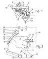
- Fig. 2:
- herausgezeichnet als Detailzeichnung den Antrieb der Setzgutschwinge mit Einsatz eines hydraulischen Hub- und Bremszylinders, und
- Fig. 3:
- die Auf- und Abbewegung der Setzgutschwinge der Figur 2 gesehen am Anlenkpunkt des Hub- und Bremszylinders, in einem Diagramm, bei dem die Hubhöhe h [m] über der Zeit t[sec] aufgetragen ist.
- Bei der Stauchsetzmaschine der Figur 1 findet die Dichtesörtierung der aufgegebenen Rohkohle 10 in einem Rohkohle 10 in einem Wasserbad 11 statt. Die zum Sortieren erforderliche Auflockerung dos Gutes wird durch Hochschwenken und Niederschwenken einer im Wasserbad 11 liegenden Setzgutschwinge 12 mit Schwenkachse 13 erzeugt. An eine Quertraverse der Schwinge 12 ist an einem Anlenkpunkt 14 die Kobenstange 15 eines Hydraulikzylinders angelenkt, der erfindungsgemäß als Hub- und Bremszylinder 16 ausgebildet ist. Die einen Teil eines Kreisbogens darstellende Hubhöhe, der Schwinge 12 ist durch den Doppelpfeil 17 angezeigt. Bei einem Aufnahmegewicht der Schwinge 12 inklusive Gutmaterial von ca. 4000 bis 5000 kg beträgt die Hubhöhe 17 der Schwinge z. B. ca. 300 bis 400 mm bei einer Hubfrequenz von z. B. 40 Hüben pro Minute.
- Der Transport des zu sortierenden Gutes 10 durch die Stauchsetzmaschine erfolgt durch die Bewegungen der Schwinge 12 sowie durch den Gut-Böschungsdruck. Während die spezifisch schwereren Berge 18 über eine Austragswalze 19 abgezogen werden, werden die spezifisch leichtere Kohle sowie das Mittelgut 20 über eine eigene Rutsche abgezogen. Beide Produkte, nämlich Berge und Kohle/Mittelgut werden getrennt voneinander durch ein Zwillings-Heberad 21 aus der Setzmaschine ausgetragen und dabei entwässert, während das durch den Setzgutträger in das Fass gefallene Feingut 22 unten aus der Setzmaschine ausgetragen und einer Feinkornsortierung zugeführt wird.
- In den in Figur 2 vergrößert herausgezeichneten gelenkig gelagerten Hub- und Bremszylinder 16 ist eine Wegmessung 23 des Kolbens 24 integriert, wobei das Messsignal über eine Signalleitung einem Wegaufnehmer 25 zugeleitet wird, der wiederum über eine Signalleitung 26 mit einem Regler 27 in Verbindung steht. An den Arbeitsraum des Zylinders 16 ist eine Druckölzuführungs- und -abführungsleitung 28 angeschlossen, in die ein Proportionatregelventil 29 integriert ist. Der Hub- und Bremszylinder 16 steht über den Regler 27 über eine weitere Signalleitung 30 mit dem Proportionalregelventil 29 in Wirkverbindung zur Steuerung der Aufwärtsbewegung und der Abwartsbewegung und damit der Hubhöhe 17 und/oder der Hubfrequenz der Setzgutschwinge 12.
- Wie aus dem Arbeitsdiagramm der Figur 3 deutlich hervorgeht ist der Arbeitszyklus des Hub- und Bremszylinders 16 aus drei Phasen zusammengesetzt, nämlich aus der Anhebephase der Schwinge 12. der Freien-Fall-Phase der Schwinge und einer Abbremsphase der Schwinge, wobei alle drei Phasen jeweils für sich steuerbar sind. Die Differenz zwischen der oberen und unteren Kolbenstellung des Hub- und Bremszylinders 16 entspricht der Hubhöhe 17 der Schwinge 12 von z. B. 350 mm, wobei der Hubhöhenbereich zwischen den Grenzen des oberen Totpunktes OT und des unteren Totpunktes UT des Zylinderkolbens 24 liegt.
- Das Proportionalregelventil 29 ist in das Druckölnetz zwischen der motorisch angetriebenen Hydraulikölpumpe 31 des Hydraulikaggregates und dem Arbeitsraum des Hub- und Bremszylinders 16 eingeschaltet.
- Der Regeleingriff auf das Proporlionalregelventil 29 erfolgt in der Weise, dass zum Anheben, d. h. zur Aufwärtsbewegung der Schwinge 12 Drucköl durch die Druckülzuführungs- und Abführungsleitung 28 in den Arbeitsraum des Hub- und Bremszylinders 16 bis vor Erreichen des oberen Totpunktes OT eingeführt wird, und dass zum Absenken der Schwinge 12 diese zunächst in freiem Fall fällt unter Verdrängung von Drucköl aus dem Zylinderarbeitsraum und Druckölabführung durch dieselbe Leitung 28 mit sich daran anschließender hydraulischer Abbremsung des Zylinderkolbens 24 vor Erreichen des unteren Totpunktes UT.
- Gemäß Diagramm der Figur 3 beträgt die Zeit für einen Arbeitszyklus des Hub- und Bremszylinders 16 bei einer Schwingenhubhöhe von 350 mm 1,36 sec, was einer Hubfrequenz f = 44 entspricht. Ein im Proportionalregelventil 29 enthaltenes steuerbares elektronisches Taktgebersystem 32 sorgt für die zeitlich genau abgestimmte Beaufschlagung der Druckölleitung 28 zwecks Einhaltung der jeweils drei aufeihanderfolgenden periodischen Zeitintervalle für die Anhebephase, Freie-Fall-Phase und Abbremsphase der Schwinge 12, wobei diese drei Phasen jeweils einen Arbeitszyklus des Hub- und Bremszylinders 16 ergeben.
Claims (5)
- Stauch-Setzmaschine zur Sortierung von Feststoffgemischen wie Rohkohle oder andere Mineralien in einer Trennflüssigkeit wie Wasser nach der Dichte, insbesondere zur Vorabscheidung von Bergen, mit einer im Wasserbad schwenkbaren den Setzgutträger und das Setzgut tragenden Schwinge (12), die durch einen angelenkten Hydraulikzylinder (16) einen Aufwärtshub und durch Fallenlassen unter Schwerkrafteinwirkung einen Abwärtshub erfährt, gekennzeichnet durch folgende Merkmale:a) der Hydraulikzylinder ist als Hub- und Bremszylinder (16) ausgebildet mit integrierter Zylinderkolben-Wegmessung (23),b) an den Arbeitsraum des Zylinders (16) ist eine Druckölzuführungs- und Abführungsleitung (28) angeschlossen, in die ein Proportionalregelventil (29) integriert ist,c) der Wegaufnehmer (25) des Hub- und Bremszylinders (16) steht über einen Regler (27) mit dem Proportionalregelventil (29) in Wirkverbindung zur Steuerung der Aufwärtsbewegung und der Abwärtsbewegung und damit der Hubhöhe (17) und/oder der Hubfrequenz der Schwinge (12),d) der Regeleingriff auf das Proportionalregelventil (29) erfolgt in der Weise, dass zum Anheben der Schwinge (12) Drucköl durch die Druckölzuführungs- und-abführungsleitung (28) in den Arbeitsraum des Hub- und Bremszylinders (16) bis vor Erreichen des oberen Totpunktes (OT) eingeführt wird, und dass zum Absenken der Schwinge (12) diese zunächst in freiem Fall fällt unter Verdrängung von Drucköl aus dem Zylinder-Arbeitsraum und Druckölabführung durch dieselbe Leitung (28) mit sich daran anschließender hydraulischer Abbremsung des Zylinderkolbens (24) vor Erreichen des unteren
- Setzmaschine nach Anspruch 1,
dadurch gekennzeichnet, dass der Arbeitszyklus des Hub- und Bremszylinders (16) aus der Anhebephase der Schwinge (12), der Freien-Fall-Phase der Schwinge und der Abbremsphase der Schwinge zusammengesetzt ist, wobei alle drei Phasen jeweils für sich steuerbar sind. - Setzmaschine nach Anspruch 1,
dadurch gekennzeichnet, dass die Differenz zwischen der oberen und unteren Kolbenstellung des Hub- und Bremszylinders (16) der Hubhöhe (17) der Schwinge (12) entspricht, wobei der Hubhöhenbereich zwischen den Grenzen des oberen Totpunktes (OT) und des unteren Totpunktes (UT) des Zylinderkolbens (24) liegt. - Setzmaschine nach Anspruch 1,
dadurch gekennzeichnet, dass der mit dem Wegaufnehmer (25) des Hub- und Bremszylinders (16) über eine Signalleitung verbundene Regler (27) über eine weitere Signalleitung (30) mit dem Proportionalregelventil (29) verbunden ist, das in das Druckölnetz zwischen Druckölpumpe (31) und Arbeitsraum des Hub- und Bremszylinders (16) eingeschaltet ist. - Setzmaschine nach Anspruch 1,
dadurch gekennzeichnet, dass das Proportionalregelventil (29) ein steuerbares elektronisches Taktgebersystem (32) aufweist.
Applications Claiming Priority (3)
| Application Number | Priority Date | Filing Date | Title |
|---|---|---|---|
| DE10255321 | 2002-11-27 | ||
| DE10255321A DE10255321A1 (de) | 2002-11-27 | 2002-11-27 | Stauch-Setzmaschine |
| PCT/EP2003/012933 WO2004047996A1 (de) | 2002-11-27 | 2003-11-19 | Stauch-setzmaschine |
Publications (2)
| Publication Number | Publication Date |
|---|---|
| EP1567276A1 EP1567276A1 (de) | 2005-08-31 |
| EP1567276B1 true EP1567276B1 (de) | 2007-07-04 |
Family
ID=32318725
Family Applications (1)
| Application Number | Title | Priority Date | Filing Date |
|---|---|---|---|
| EP03767572A Expired - Lifetime EP1567276B1 (de) | 2002-11-27 | 2003-11-19 | Stauch-setzmaschine |
Country Status (8)
| Country | Link |
|---|---|
| US (1) | US7571815B2 (de) |
| EP (1) | EP1567276B1 (de) |
| CN (1) | CN1318145C (de) |
| AT (1) | ATE366143T1 (de) |
| AU (1) | AU2003292044B2 (de) |
| DE (2) | DE10255321A1 (de) |
| WO (1) | WO2004047996A1 (de) |
| ZA (1) | ZA200504211B (de) |
Families Citing this family (8)
| Publication number | Priority date | Publication date | Assignee | Title |
|---|---|---|---|---|
| CN101823016B (zh) * | 2010-03-19 | 2012-07-04 | 陈义 | 湿式振摆联合重力选矿机 |
| DE102012201042A1 (de) | 2012-01-25 | 2013-07-25 | Mbe Coal & Minerals Technology Gmbh | Verfahren zum Betrieb einer Luftsetzmaschine |
| CN104863912B (zh) * | 2014-11-06 | 2017-05-24 | 山东泰安煤矿机械有限公司 | 用于动筛跳汰机的液控系统 |
| CN104747622A (zh) * | 2015-02-06 | 2015-07-01 | 张斐斐 | 一种振动分选机转轴制动器 |
| CN205518163U (zh) * | 2016-01-26 | 2016-08-31 | 张路征 | 联体三产品动筛跳汰机 |
| EP3837054B1 (de) * | 2018-08-17 | 2025-11-26 | Pulsating Jigs International (Pty) Ltd | Trennvorrichtung und -verfahren |
| WO2025101165A1 (en) * | 2023-11-08 | 2025-05-15 | Kazarova Iryna Volodymyrivna | Jigging machine and the method of controlling the sieve movement of the jigging machine using the drive system |
| CN119406559B (zh) * | 2024-11-28 | 2025-07-18 | 鹤壁市鹤润工贸有限公司 | 一种跳汰选煤装置 |
Family Cites Families (9)
| Publication number | Priority date | Publication date | Assignee | Title |
|---|---|---|---|---|
| DE2734736C2 (de) * | 1977-08-02 | 1984-08-16 | Klöckner-Humboldt-Deutz AG, 5000 Köln | Austragssteuerverfahren für eine druckluftgesteuerte Naßsetzmaschine |
| DE3322137A1 (de) * | 1983-06-20 | 1984-12-20 | Krupp Polysius Ag, 4720 Beckum | Stauchsetzmaschine |
| GB2141641B (en) * | 1983-06-20 | 1986-04-30 | Krupp Polysius Ag | Percussion jig |
| DE3428824A1 (de) * | 1984-08-04 | 1986-02-13 | Klöckner-Humboldt-Deutz AG, 5000 Köln | Verfahren und vorrichtung zur regelung einer setzmaschine, insbesondere einer stauchsetzmaschine |
| DE3531240C2 (de) * | 1984-10-09 | 1987-02-12 | MAN Gutehoffnungshütte GmbH, 4200 Oberhausen | Elektronische Ventilsteuerung für Setzmaschinen |
| US5207742A (en) * | 1992-03-09 | 1993-05-04 | Svedala Industries, Inc. | Control apparatus for coal/mineral jigs |
| DE4302672C1 (de) * | 1993-01-30 | 1994-05-26 | Ruhrkohle Ag | Setzmaschine mit pneumatischer Ventilsteuerung |
| AUPN531995A0 (en) * | 1995-09-08 | 1995-10-05 | University Of Queensland, The | Dynamic monitoring and control of jigs |
| DE102004048071A1 (de) * | 2004-10-02 | 2006-04-20 | Ina-Schaeffler Kg | Ventiltrieb für ein nockenbetätigtes Hubventil |
-
2002
- 2002-11-27 DE DE10255321A patent/DE10255321A1/de not_active Withdrawn
-
2003
- 2003-11-19 US US10/536,521 patent/US7571815B2/en not_active Expired - Lifetime
- 2003-11-19 AU AU2003292044A patent/AU2003292044B2/en not_active Expired
- 2003-11-19 DE DE50307630T patent/DE50307630D1/de not_active Expired - Lifetime
- 2003-11-19 EP EP03767572A patent/EP1567276B1/de not_active Expired - Lifetime
- 2003-11-19 WO PCT/EP2003/012933 patent/WO2004047996A1/de not_active Ceased
- 2003-11-19 CN CNB2003801044312A patent/CN1318145C/zh not_active Expired - Lifetime
- 2003-11-19 AT AT03767572T patent/ATE366143T1/de not_active IP Right Cessation
-
2005
- 2005-05-24 ZA ZA2005/04211A patent/ZA200504211B/en unknown
Non-Patent Citations (1)
| Title |
|---|
| None * |
Also Published As
| Publication number | Publication date |
|---|---|
| EP1567276A1 (de) | 2005-08-31 |
| ZA200504211B (en) | 2006-02-22 |
| WO2004047996A1 (de) | 2004-06-10 |
| CN1318145C (zh) | 2007-05-30 |
| WO2004047996A9 (de) | 2005-07-21 |
| AU2003292044B2 (en) | 2008-10-23 |
| US7571815B2 (en) | 2009-08-11 |
| DE50307630D1 (de) | 2007-08-16 |
| ATE366143T1 (de) | 2007-07-15 |
| DE10255321A1 (de) | 2004-06-17 |
| AU2003292044A1 (en) | 2004-06-18 |
| CN1717281A (zh) | 2006-01-04 |
| US20060163123A1 (en) | 2006-07-27 |
Similar Documents
| Publication | Publication Date | Title |
|---|---|---|
| US5749471A (en) | Vibrating screen | |
| CN104001665B (zh) | 一种带式直线振动筛 | |
| CN202725483U (zh) | 全自动筛沙送料机 | |
| EP1567276B1 (de) | Stauch-setzmaschine | |
| CN112620098A (zh) | 一种矿石开采用防堵塞式振动筛 | |
| CN103934204A (zh) | 垃圾处理预分选装置 | |
| CN206229640U (zh) | 一种具有调节进料装置的茶叶抖筛机 | |
| CN107470133A (zh) | 一种可移动自动筛沙装置 | |
| CN118357153A (zh) | 一种建筑垃圾分离装置 | |
| DE3724199C2 (de) | ||
| CN209061586U (zh) | 一种反光玻璃微珠的智能筛选和配比设备 | |
| CN102847677A (zh) | 全自动筛沙送料机 | |
| CN117732719A (zh) | 一种自动出料多层筛分装置及方法 | |
| CN210187238U (zh) | 一种矸石粉碎筛分一体化装置 | |
| CN116764791A (zh) | 一种履带移动破筛一体机及其使用方法 | |
| CN201625630U (zh) | 圆振动筛 | |
| US1128807A (en) | Jig. | |
| CN220091671U (zh) | 一种跳汰机跳汰室下降水速度调节装置 | |
| CN215940527U (zh) | 一种环境科学细粒物质分离装置 | |
| CN209254826U (zh) | 一种废石料粉碎装置 | |
| EP0002195B1 (de) | Presse zum Verpressen von Krümeln eines elastomeren Materials zu Ballen | |
| US2100459A (en) | Jigging machine for concentrating ores and other materials | |
| DE542754C (de) | Ruettelformmaschine | |
| DE914121C (de) | Kolbenbetriebene Nasssetzmaschine fuer Kohle, Erze od. dgl. | |
| US1881230A (en) | Milling machine |
Legal Events
| Date | Code | Title | Description |
|---|---|---|---|
| PUAI | Public reference made under article 153(3) epc to a published international application that has entered the european phase |
Free format text: ORIGINAL CODE: 0009012 |
|
| 17P | Request for examination filed |
Effective date: 20050518 |
|
| AK | Designated contracting states |
Kind code of ref document: A1 Designated state(s): AT BE BG CH CY CZ DE DK EE ES FI FR GB GR HU IE IT LI LU MC NL PT RO SE SI SK TR |
|
| AX | Request for extension of the european patent |
Extension state: AL LT LV MK |
|
| DAX | Request for extension of the european patent (deleted) | ||
| GRAP | Despatch of communication of intention to grant a patent |
Free format text: ORIGINAL CODE: EPIDOSNIGR1 |
|
| GRAS | Grant fee paid |
Free format text: ORIGINAL CODE: EPIDOSNIGR3 |
|
| GRAA | (expected) grant |
Free format text: ORIGINAL CODE: 0009210 |
|
| AK | Designated contracting states |
Kind code of ref document: B1 Designated state(s): AT BE BG CH CY CZ DE DK EE ES FI FR GB GR HU IE IT LI LU MC NL PT RO SE SI SK TR |
|
| REG | Reference to a national code |
Ref country code: GB Ref legal event code: FG4D Free format text: NOT ENGLISH |
|
| REG | Reference to a national code |
Ref country code: CH Ref legal event code: EP |
|
| REG | Reference to a national code |
Ref country code: IE Ref legal event code: FG4D Free format text: LANGUAGE OF EP DOCUMENT: GERMAN |
|
| REF | Corresponds to: |
Ref document number: 50307630 Country of ref document: DE Date of ref document: 20070816 Kind code of ref document: P |
|
| RAP2 | Party data changed (patent owner data changed or rights of a patent transferred) |
Owner name: KHD HUMBOLDT WEDAG GMBH |
|
| NLT2 | Nl: modifications (of names), taken from the european patent patent bulletin |
Owner name: KHD HUMBOLDT WEDAG GMBH Effective date: 20070829 |
|
| NLV1 | Nl: lapsed or annulled due to failure to fulfill the requirements of art. 29p and 29m of the patents act | ||
| GBV | Gb: ep patent (uk) treated as always having been void in accordance with gb section 77(7)/1977 [no translation filed] |
Effective date: 20070704 |
|
| PG25 | Lapsed in a contracting state [announced via postgrant information from national office to epo] |
Ref country code: PT Free format text: LAPSE BECAUSE OF FAILURE TO SUBMIT A TRANSLATION OF THE DESCRIPTION OR TO PAY THE FEE WITHIN THE PRESCRIBED TIME-LIMIT Effective date: 20071204 Ref country code: FI Free format text: LAPSE BECAUSE OF FAILURE TO SUBMIT A TRANSLATION OF THE DESCRIPTION OR TO PAY THE FEE WITHIN THE PRESCRIBED TIME-LIMIT Effective date: 20070704 Ref country code: SI Free format text: LAPSE BECAUSE OF FAILURE TO SUBMIT A TRANSLATION OF THE DESCRIPTION OR TO PAY THE FEE WITHIN THE PRESCRIBED TIME-LIMIT Effective date: 20070704 Ref country code: ES Free format text: LAPSE BECAUSE OF FAILURE TO SUBMIT A TRANSLATION OF THE DESCRIPTION OR TO PAY THE FEE WITHIN THE PRESCRIBED TIME-LIMIT Effective date: 20071015 Ref country code: NL Free format text: LAPSE BECAUSE OF FAILURE TO SUBMIT A TRANSLATION OF THE DESCRIPTION OR TO PAY THE FEE WITHIN THE PRESCRIBED TIME-LIMIT Effective date: 20070704 Ref country code: BG Free format text: LAPSE BECAUSE OF FAILURE TO SUBMIT A TRANSLATION OF THE DESCRIPTION OR TO PAY THE FEE WITHIN THE PRESCRIBED TIME-LIMIT Effective date: 20071004 |
|
| EN | Fr: translation not filed | ||
| REG | Reference to a national code |
Ref country code: IE Ref legal event code: FD4D |
|
| PG25 | Lapsed in a contracting state [announced via postgrant information from national office to epo] |
Ref country code: DK Free format text: LAPSE BECAUSE OF FAILURE TO SUBMIT A TRANSLATION OF THE DESCRIPTION OR TO PAY THE FEE WITHIN THE PRESCRIBED TIME-LIMIT Effective date: 20070704 Ref country code: GR Free format text: LAPSE BECAUSE OF FAILURE TO SUBMIT A TRANSLATION OF THE DESCRIPTION OR TO PAY THE FEE WITHIN THE PRESCRIBED TIME-LIMIT Effective date: 20071005 |
|
| PLBE | No opposition filed within time limit |
Free format text: ORIGINAL CODE: 0009261 |
|
| STAA | Information on the status of an ep patent application or granted ep patent |
Free format text: STATUS: NO OPPOSITION FILED WITHIN TIME LIMIT |
|
| PG25 | Lapsed in a contracting state [announced via postgrant information from national office to epo] |
Ref country code: SK Free format text: LAPSE BECAUSE OF FAILURE TO SUBMIT A TRANSLATION OF THE DESCRIPTION OR TO PAY THE FEE WITHIN THE PRESCRIBED TIME-LIMIT Effective date: 20070704 Ref country code: IE Free format text: LAPSE BECAUSE OF FAILURE TO SUBMIT A TRANSLATION OF THE DESCRIPTION OR TO PAY THE FEE WITHIN THE PRESCRIBED TIME-LIMIT Effective date: 20070704 Ref country code: CZ Free format text: LAPSE BECAUSE OF FAILURE TO SUBMIT A TRANSLATION OF THE DESCRIPTION OR TO PAY THE FEE WITHIN THE PRESCRIBED TIME-LIMIT Effective date: 20070704 Ref country code: GB Free format text: LAPSE BECAUSE OF FAILURE TO SUBMIT A TRANSLATION OF THE DESCRIPTION OR TO PAY THE FEE WITHIN THE PRESCRIBED TIME-LIMIT Effective date: 20070704 |
|
| BERE | Be: lapsed |
Owner name: KHD HUMBOLDT WEDAG G.M.B.H. Effective date: 20071130 |
|
| 26N | No opposition filed |
Effective date: 20080407 |
|
| PG25 | Lapsed in a contracting state [announced via postgrant information from national office to epo] |
Ref country code: RO Free format text: LAPSE BECAUSE OF FAILURE TO SUBMIT A TRANSLATION OF THE DESCRIPTION OR TO PAY THE FEE WITHIN THE PRESCRIBED TIME-LIMIT Effective date: 20070704 Ref country code: MC Free format text: LAPSE BECAUSE OF NON-PAYMENT OF DUE FEES Effective date: 20071130 Ref country code: SE Free format text: LAPSE BECAUSE OF FAILURE TO SUBMIT A TRANSLATION OF THE DESCRIPTION OR TO PAY THE FEE WITHIN THE PRESCRIBED TIME-LIMIT Effective date: 20071004 |
|
| PG25 | Lapsed in a contracting state [announced via postgrant information from national office to epo] |
Ref country code: FR Free format text: LAPSE BECAUSE OF FAILURE TO SUBMIT A TRANSLATION OF THE DESCRIPTION OR TO PAY THE FEE WITHIN THE PRESCRIBED TIME-LIMIT Effective date: 20080229 Ref country code: LI Free format text: LAPSE BECAUSE OF NON-PAYMENT OF DUE FEES Effective date: 20071130 Ref country code: CH Free format text: LAPSE BECAUSE OF NON-PAYMENT OF DUE FEES Effective date: 20071130 |
|
| REG | Reference to a national code |
Ref country code: CH Ref legal event code: PL |
|
| PG25 | Lapsed in a contracting state [announced via postgrant information from national office to epo] |
Ref country code: BE Free format text: LAPSE BECAUSE OF NON-PAYMENT OF DUE FEES Effective date: 20071130 |
|
| PG25 | Lapsed in a contracting state [announced via postgrant information from national office to epo] |
Ref country code: EE Free format text: LAPSE BECAUSE OF FAILURE TO SUBMIT A TRANSLATION OF THE DESCRIPTION OR TO PAY THE FEE WITHIN THE PRESCRIBED TIME-LIMIT Effective date: 20070704 |
|
| PG25 | Lapsed in a contracting state [announced via postgrant information from national office to epo] |
Ref country code: AT Free format text: LAPSE BECAUSE OF NON-PAYMENT OF DUE FEES Effective date: 20071119 |
|
| PG25 | Lapsed in a contracting state [announced via postgrant information from national office to epo] |
Ref country code: CY Free format text: LAPSE BECAUSE OF FAILURE TO SUBMIT A TRANSLATION OF THE DESCRIPTION OR TO PAY THE FEE WITHIN THE PRESCRIBED TIME-LIMIT Effective date: 20070704 |
|
| PG25 | Lapsed in a contracting state [announced via postgrant information from national office to epo] |
Ref country code: LU Free format text: LAPSE BECAUSE OF NON-PAYMENT OF DUE FEES Effective date: 20071119 |
|
| PG25 | Lapsed in a contracting state [announced via postgrant information from national office to epo] |
Ref country code: TR Free format text: LAPSE BECAUSE OF FAILURE TO SUBMIT A TRANSLATION OF THE DESCRIPTION OR TO PAY THE FEE WITHIN THE PRESCRIBED TIME-LIMIT Effective date: 20070704 Ref country code: HU Free format text: LAPSE BECAUSE OF FAILURE TO SUBMIT A TRANSLATION OF THE DESCRIPTION OR TO PAY THE FEE WITHIN THE PRESCRIBED TIME-LIMIT Effective date: 20080105 |
|
| PG25 | Lapsed in a contracting state [announced via postgrant information from national office to epo] |
Ref country code: IT Free format text: LAPSE BECAUSE OF NON-PAYMENT OF DUE FEES Effective date: 20071130 |
|
| REG | Reference to a national code |
Ref country code: DE Ref legal event code: R082 Ref document number: 50307630 Country of ref document: DE Ref country code: DE Ref legal event code: R082 Ref document number: 50307630 Country of ref document: DE Representative=s name: HUMBOLDT-PATENT HUEBNER NEUMANN RADWER WENZEL, DE Ref country code: DE Ref legal event code: R082 Ref document number: 50307630 Country of ref document: DE Representative=s name: DLA PIPER UK LLP, DE |
|
| REG | Reference to a national code |
Ref country code: DE Ref legal event code: R082 Ref document number: 50307630 Country of ref document: DE Ref country code: DE Ref legal event code: R082 Ref document number: 50307630 Country of ref document: DE Representative=s name: DLA PIPER UK LLP, DE |
|
| REG | Reference to a national code |
Ref country code: DE Ref legal event code: R082 Ref document number: 50307630 Country of ref document: DE Representative=s name: DLA PIPER UK LLP, DE Ref country code: DE Ref legal event code: R081 Ref document number: 50307630 Country of ref document: DE Owner name: MBE COAL & MINERALS TECHNOLOGY HOLDING GMBH, DE Free format text: FORMER OWNER: MBE COAL & MINERALS TECHNOLOGY GMBH, 51105 KOELN, DE |
|
| PGFP | Annual fee paid to national office [announced via postgrant information from national office to epo] |
Ref country code: DE Payment date: 20221128 Year of fee payment: 20 |
|
| REG | Reference to a national code |
Ref country code: DE Ref legal event code: R071 Ref document number: 50307630 Country of ref document: DE |