EP1566879A1 - Betütigungsglied - Google Patents
Betütigungsglied Download PDFInfo
- Publication number
- EP1566879A1 EP1566879A1 EP03774196A EP03774196A EP1566879A1 EP 1566879 A1 EP1566879 A1 EP 1566879A1 EP 03774196 A EP03774196 A EP 03774196A EP 03774196 A EP03774196 A EP 03774196A EP 1566879 A1 EP1566879 A1 EP 1566879A1
- Authority
- EP
- European Patent Office
- Prior art keywords
- stationary
- moving element
- actuator
- axial direction
- movable member
- Prior art date
- Legal status (The legal status is an assumption and is not a legal conclusion. Google has not performed a legal analysis and makes no representation as to the accuracy of the status listed.)
- Withdrawn
Links
Images










Classifications
-
- H—ELECTRICITY
- H02—GENERATION; CONVERSION OR DISTRIBUTION OF ELECTRIC POWER
- H02K—DYNAMO-ELECTRIC MACHINES
- H02K33/00—Motors with reciprocating, oscillating or vibrating magnet, armature or coil system
- H02K33/16—Motors with reciprocating, oscillating or vibrating magnet, armature or coil system with polarised armatures moving in alternate directions by reversal or energisation of a single coil system
-
- H—ELECTRICITY
- H02—GENERATION; CONVERSION OR DISTRIBUTION OF ELECTRIC POWER
- H02K—DYNAMO-ELECTRIC MACHINES
- H02K2201/00—Specific aspects not provided for in the other groups of this subclass relating to the magnetic circuits
- H02K2201/18—Machines moving with multiple degrees of freedom
Definitions
- the present invention relates an actuator which is capable of moving in two directions of an axial direction and a rotational direction.
- actuators are adapted to move in one direction of a linear direction or a rotational direction.
- a motion direction converting mechanism for converting a motion direction mechanically is employed.
- the motion direction converting mechanism converts the motion direction, noises are produced.
- Japanese Patent Laid-Open Publication No. 2002-78310 discloses an arrangement in which by making the gap nonuniform relative to axial displacement (stroke position) of the movable member, the movable member is moved in an axial direction of the shaft, i.e., in a linear direction and in a rotational direction having the axial direction as its rotational axis without using the motion direction converting mechanism.
- 2002-199689 discloses an arrangement in which a second movable member (amplitude control weight) serving to cancel inertia force of the first movable member is provided and spring members are provided among the casing, the first movable member and the second movable member such that not only by making the gap nonuniform relative to axial displacement (stroke position) of the first movable member, the first movable member performs on the basis of resonance in an axial direction of the shaft both reciprocating motion and motion in a rotational direction having the axial direction as its rotational axis without using the motion direction converting mechanism but vibrations of the first movable member due to axial inertia force can be reduced.
- a second movable member amplitude control weight
- an object of the present invention is, with a view to eliminating the above mentioned drawbacks of prior art, to upgrade degree of freedom of operational control of the movable member.
- an actuator of the present invention includes a casing.
- a stationary member has a coil member and is mounted in the casing.
- a movable member includes a moving element and is supported by the casing.
- the moving element has a shaft and is supported by the casing so as to be moved in an axial direction of the shaft and in a rotational direction having the axial direction of the shaft as its rotational axis. Electric current is caused to flow through the coil member such that the moving element is moved in the axial direction and in the rotational direction.
- the stationary member includes a first stationary member for imparting to the movable member a force oriented in the axial direction and a second stationary member for imparting to the movable member a force oriented in the rotational direction.
- the coil member includes a first coil member for exciting a first magnetic path passing through the first stationary member and a second coil member for exciting a second magnetic path passing through the second stationary member.
- Figs. 1 to 10 show an actuator according to a first embodiment of the present invention.
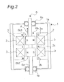
- this actuator mainly includes a casing 1, a pair of first stationary members 2 each having a first coil 3 wound therearound, a pair of second stationary members 4 each having a second coil 5 wound therearound and a movable member 6.
- the movable member 6 includes a shaft 6a and a driving force generator 6b secured to the shaft 6a.
- the casing 1 includes a housing portion 1a and a pair of bearing portions 1 b and accommodates the first and second stationary members 2 and 4 and the movable member 6.
- the housing portion 1a is formed by metallic magnetic material into a cylindrical shape having a closed bottom.
- each of the bearing portions 1b is formed by a so-called ball bearing in which metal balls each having a smoothly worked surface are fitted into a cavity of a cylindrical tube having a concentric section.
- the two bearing portions 1b are, respectively, provided at centers of opposite end faces of the housing portion 1a such that a central axis of the housing portion 1a and a central axis of the bearing portions 1b coincide with each other.
- the two bearing portions 1b support the shaft 6a by the metal balls such that the shaft 6a of the movable member 6, namely, the movable member 6 can be moved in an axial direction of the shaft 6a, (hereinafter, referred to as the "axial direction") and in a rotational direction having the axial direction as its central axis, i.e., as its rotational axis, (hereinafter, referred to as the "rotational direction").
- Each of the first stationary members 2 is formed by magnetic material into a pillar having an E-shaped section and has three magnetic pole potions arranged symmetrically in the axial direction, namely, magnetic pole portions 2a and 2b disposed at its opposite ends and a central magnetic pole portion 2c.
- the two first stationary members 2 are mounted in a hollow of the housing portion 1 a of the casing 1 so as to be disposed symmetrically with respect to the rotational axis.
- the magnetic pole portions 2a to 2c of the first stationary member 2 have an identical width and an identical length
- the first coil 3 is wound around the central magnetic pole portion 2c and different magnetic poles are produced at the central magnetic pole portion 2c and the opposite magnetic pole portions 2a and 2b by causing electric current to flow through the first coil 3.
- the first stationary member 2 forms an efficient magnetic circuit in which leakage flux is small.
- the two first stationary members 2 are mainly used for applying to the movable member 6 a force oriented in the axial direction.
- the first coil 3 is wound around the central magnetic pole portion 2c of the first stationary member 2 via a resinous coil bobbin (not shown).
- the first coil 3 is adapted to excite a magnetic path passing through the first stationary member 2, a gap between the first stationary member 2 and the movable member 6 and the movable member 6.
- the first coil 3 provided in one of the two first stationary members 2 and the first coil 3 provided in the other first stationary member 2 are connected to each other so as to perform excitation in an antiphase manner. For example, as shown in Fig. 2, when the central magnetic pole portion 2c of the one first stationary member 2 is excited to the N-pole, the central magnetic pole 2c of the other first stationary member 2 is excited to the S-pole upon connection of the two first coils 3.
- Each of the second stationary members 4 is formed by magnetic material into a pillar having a C-shaped section and has two magnetic pole portions 4a and 4b arranged symmetrically in the axial direction.
- the two second stationary members 4 are mounted in the hollow of the housing portion 1a of the casing 1 so as to be disposed symmetrically with respect to the rotational axis.
- an axial plane containing the two first stationary members 2 and an axial plane containing the two second stationary members 4 intersect with each other orthogonally.
- the magnetic pole portions 4a and 4b of the second stationary member 4 have an identical width and an identical length. Meanwhile, as shown in Fig. 3, in each of the second stationary members 4, the second coil 5 is dividedly wound around the magnetic pole portions 4a and 4b and different magnetic poles are produced at the magnetic pole portions 4a and 4b by causing electric current to flow through the second coil 5. For example, as shown in Fig. 3, if an S-pole is produced at the magnetic pole portion 2a, an N-pole is produced at the magnetic pole portion 4b. Since the magnetic pole portions 4a and 4b are positioned so as to confront the movable member 6, the second stationary member 4 forms an efficient magnetic circuit in which leakage flux is small. The two second stationary members 4 are mainly used for applying to the movable member 6 a force oriented in the rotational direction.
- the second coil 5 is dividedly wound around the magnetic pole portions 4a and 4b by way of a resinous coil bobbin for each of the magnetic pole portions 4a and 4b.
- the second coil 5 is adapted to excite a magnetic path passing through the second stationary member 4, a gap between the second stationary member 4 and the movable member 6 and the movable member 6.
- the second coil 5 provided in one of the two second stationary members 4 and the second coil 5 provided in the other second stationary member 4 are connected to each other so as to perform excitation in an antiphase manner. For example, as shown in Fig. 3, when the magnetic pole portion 4a of the one second stationary member 4 is excited to the S-pole, the magnetic pole portion 4a of the other second stationary member 4 is excited to the N-pole upon connection of the two second coils 5.
- the movable member 6 includes the shaft 6a and the driving force generator 6b.
- the shaft 6a is formed by a metallic cylinder and is supported by the two bearing portions 1b so as to be moved in the axial direction and in the rotational direction.
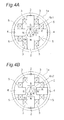
- the driving force generator 6b is formed by two cylindrical and tubular magnets 6b1 and 6b2 magnetized radially such that a magnetization direction, i.e., a direction of orientation from the S-pole to the N-pole in the magnet 6b1 is opposite to that of the magnet 6b2 as shown in Figs. 4A and 4B.
- the magnets 6b1 and 6b2 are mounted on the shaft 6a such that a central axis of the magnets 6b1 and 6b1 coincides with that of the shaft 6a.
- the magnets 6b1 and 6b2 are provided symmetrically with respect to the rotational axis such that the magnetization directions of the magnets 6b1 and 6b2 intersect with the axial direction orthogonally. Therefore, since masses of the magnets 6b1 and 6b2 are distributed symmetrically with respect to the rotational axis, inertia force based on motion of the movable member 6 in the rotational direction is cancelled and thus, vibrations to be transmitted to the casing 1 can be reduced.
- the movable member 6 can be moved with great force.
- the driving force generator 6b of the movable member 6 has a cylindrical magnetic pole face, while the magnetic pole portions of the first and second stationary members 2 and 4 have flat magnetic pole faces.
- each of the magnets 6b1 and 6b2 has a thickness equal to a width of each recess of the first stationary member 2 having the E-shaped magnetic pole portions 2a to 2c.
- the magnets 6b1 and 6b2 are provided on the shaft 6a so as to be spaced away from each other in the axial direction such that a side face of each of the magnets 6b1 and 6b2 confronts each recess of the first stationary member 2.
- the magnets 6b1 and 6b2 confront the magnetic pole portions 4a and 4b of the second stationary member 4, respectively as shown in Fig. 3.
- a diameter of the magnets 6b1 and 6b2 is set such that a gap is formed between the circular magnetic pole face of the driving force generator 6b of the movable member 6 and each of the flat magnetic pole faces of the magnetic pole portions of the first and second stationary members 2 and 4
- magnetic poles shown in, for example, Fig. 2 are, respectively, produced in the magnetic pole portions 2a to 2c of the first stationary member 2. Then, the magnet 6b1 undergoes an attraction force and a repulsion force from the upper magnetic pole portion 2a and the central magnetic pole portion 2c of the first stationary member 2, respectively. On the other hand, the magnet 6b2 undergoes an attraction force and a repulsion force from the central magnetic pole portion 2c and the lower magnetic pole portion 2b of the first stationary member 2, respectively. Therefore, the movable member 6 undergoes from the first stationary member 2 a force oriented in the axial direction, i.e., in the upward direction of the arrow A in Fig. 2.
- the movable member 6 undergoes from the second stationary members 4 the force oriented in the clockwise rotational direction. Meanwhile, if electric current is caused to flow through the second coil 5 in the direction opposite to the above, polarities of the magnetic poles produced at the magnetic pole portions 4a and 4b of the second stationary member 4 become opposite to those of the above, so that a force oriented in a counterclockwise rotational direction is applied to the movable member 6.
- the actuator has thrust characteristics relative to axial displacement as shown in Fig. 5 and torque characteristics relative to rotational angle in the rotational direction as shown in Fig. 6.
- a curve FZ1 represents thrust characteristics obtained at the time electric current does not flow through the first coil 3
- a curve FP1 represents thrust characteristics obtained at the time electric current flows through the first coil 3 in a plus direction
- a curve FM1 represents thrust characteristics obtained at the time electric current flows through the first coil 3 in a minus direction.
- Fig. 5 a curve FZ1 represents thrust characteristics obtained at the time electric current does not flow through the first coil 3
- a curve FP1 represents thrust characteristics obtained at the time electric current flows through the first coil 3 in a plus direction
- a curve FM1 represents thrust characteristics obtained at the time electric current flows through the first coil 3 in a minus direction.
- a curve TZ1 represents torque characteristics obtained at the time electric current does not flow through the second coil 5
- a curve TP1 represents torque characteristics obtained at the time electric current flows through the second coil 5 in a plus direction
- a curve TM1 represents torque characteristics obtained at the time electric current flows through the second coil 5 in a minus direction.
- a layout in which the first stationary members 2 and the movable member 6 are disposed as shown in Fig 2 is employed as a reference position in the axial direction
- a layout in which the first stationary members 2, the second stationary members 4 and the movable member 6 are disposed as shown in Figs. 4A and 4B is employed as a reference position in the rotational direction. Therefore, if an AC voltage is applied to the first coil 3 and the second coil 5, electric current flows through each of the first coil 3 and the second coil 5 in the plus and minus directions, so that the movable member 6 is reciprocated in two directions of the axial direction and the rotational direction.
- the second stationary member 4 is formed into an E-shaped configuration having three magnetic pole portions, i.e., the opposite magnetic pole portions 4a and 4b and a central magnetic pole portion 4c in the same manner as the first stationary member 2.
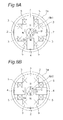
- the magnet 6b1 and the upper magnetic pole portion 4a of the second stationary member 4 are positioned relative to each other such that a force for causing the magnet 6b1 to perform clockwise rotary motion of the arrow B is generated.
- Fig. 8A the magnet 6b1 and the upper magnetic pole portion 4a of the second stationary member 4 are positioned relative to each other such that a force for causing the magnet 6b1 to perform clockwise rotary motion of the arrow B is generated.
- the magnet 6b2 and the lower magnetic pole portion 4b of the second stationary member 4 are positioned relative to each other such that a force for causing the magnet 6b2 to perform counterclockwise rotary motion of the arrow C is generated.
- a force for causing the magnet 6b2 to perform counterclockwise rotary motion of the arrow C is generated.
- the rotational direction of the magnet 6b1 is opposite to that of the magnet 6b2
- rotary motion of the magnet 6b1 and rotary motion of the magnet 6b2 cancel each other.
- the magnetic pole faces of the magnets 6b1 and 6b2 do not confront those of the second stationary member 4 as shown in Fig. 7, a force applied to the movable member 6 from the second stationary members 4 is small. Therefore, by employing the C-shaped second stationary member 4 of Fig. 1 in place of the E-shaped second stationary member 4 of Fig. 7, a force applied to the movable member 6 in the rotational direction from the second stationary members 4 can be increased.
- the movable member 6 is disposed at the reference position in the axial direction of Fig. 2 and at the reference position in the rotational direction of Figs. 4A and 4B and electric current does not flow through the first coil 3 and the second coil 5.
- the movable member 6 is in a balanced state as shown by the curve FZ1 in Fig 5. and the curve TZ1 in Fig. 6, the movable member 6 is at a standstill without undergoing any force both in the axial direction and in the rotational direction.
- Phase of AC flowing through the first coil 3 and the second coil 5 changes according to motion of the movable member 6 and the number of turns of each of the first coil 3 and the second coil 5 but the movable member 6 is moved in the axial direction as shown by, for example, a curve DS of Fig. 8 9 by AC flowing through the first coil 3.
- the second coil 5 causes the movable member 6 to perform counterclockwise rotary motion in an interval RL and clockwise rotary motion in an interval RR. Therefore, the movable member 6 performs reciprocating motion in the rotational direction at a period identical with that of the axial direction while performing reciprocating motion in the axial direction.
- motion of the movable member 6 in the axial direction and motion of the movable member 6 in the rotational direction can be controlled independently of each other as described above.
- a frequency of an AC voltage applied to the second coil 5 and indicated by a waveform VR2 is set to be twice that of an AC voltage applied to the first coil 3 and indicated by a waveform VS as shown in, for example, Fig. 10
- the movable member 6 is capable of performing two reciprocating motions in the rotational direction while performing one reciprocating motion in the axial direction.
- the force oriented in the axial direction is applied to the movable member 6 when the magnetic path passing through the first stationary member 2 is excited by the first coil 3, while the force oriented in the rotational direction is applied to the movable member 6 when the magnetic path passing through the second stationary member 4 is excited by the second coil 5.
- motion of the movable member 6 in the axial direction and motion of the movable member 6 in the rotational direction can be controlled independently of each other.
- the first stationary member 2 is formed into the E-shaped configuration having the magnetic pole portions 2a to 2c
- the second stationary member 4 is formed into the C-shaped configuration having the magnetic pole portions 4a and 4b and the first stationary members 2 and the second stationary members 4 are disposed so as to intersect with each other orthogonally, an interval between the first stationary members 2 and the second stationary members 4 becomes large, so that a space for providing the first coil 3 in the first stationary member 2 and a space for providing the second coil 5 in the second stationary member 4 can be made large.
- the magnetic pole portions 2a to 2c of the first stationary member 2 are disposed at positions suitable for producing the force oriented in the axial direction, so that the first stationary member 2 lessens leakage flux and the movable member 6 can be efficiently moved in the axial direction with great force.
- the magnetic pole portions 4a and 4b of the second stationary member 4 are disposed at positions suitable for producing the force oriented in the rotational direction, so that the second stationary member 4 lessens leakage flux and the movable member 6 can be efficiently moved in the rotational direction with great force.
- Figs. 11 and 12 show an actuator according to a second embodiment of the present invention.
- This actuator is different from the actuator of the first embodiment in shapes and relative position of the first stationary member 2 and the second stationary member 4 and other constructions of this actuator are the same as those of the actuator of the first embodiment.
- each of magnetic pole faces of magnetic pole portions of the first stationary member 2 and the second stationary member 4 is formed into a circular curved surface so as to confront the cylindrical magnetic pole face of the driving force generator 6b of the movable member 6 via a predetermined gap.
- the magnetic pole portions of the second stationary member 4 are provided in recesses among the E-shaped magnetic pole portions of the first stationary member 2.
- each of the first stationary member 2 and the second stationary member 4 secures a space for increasing an area for confronting the movable member 6, the area for confrontation between each of the first stationary member 2 and the second stationary member 4 and the movable member 6 can be increased, so that a large force can be applied to the movable member 6.
- the gap G magnetic reluctance of a magnetic path WC which does not contribute to application of a force to the movable member 6 as shown by the arrow in Fig.
- a width of the gap G is designed in view of a width of the predetermined gap between the driving force generator 6b of the movable member 6 and each of the first stationary member 2 and the second stationary member 4, etc.
- Fig. 13 shows an actuator according to a third embodiment of the present invention.
- This actuator is different from the actuator of the first embodiment in shape of the movable member 6 and relative position of the movable member 6 and the first stationary member 2 and other constructions of this actuator are the same as those of the actuator of the first embodiment.
- Each of the magnets 6b1 and 6b2 forming the driving force generator 6b of the movable member 6 is a cylindrical magnet having a thickness smaller than an axial width of the recesses among the E-shaped magnetic pole portions 2a to 2c of the first stationary member 2 and a diameter of the cylindrical magnet is formed larger than a distance between the corresponding magnetic pole portions of a pair of the first stationary members 2 such that the cylindrical magnet projects into each of the recesses among the magnetic pole portions 2a to 2c of the first stationary member 2.
- motion of the movable member 6 in the axial direction is restricted within the above recesses of the first stationary member 2.
- Figs. 14 and 15 show an actuator according to a fourth embodiment of the present invention.
- This actuator is different from the actuator of the first embodiment in shapes of the magnets 6b1 and 6b2 of the movable member 6 and other constructions of this actuator are the same as those of the actuator of the first embodiment.
- the magnets 6b1 and 6b2 of the movable member 6 are cylindrically formed into an identical size such that not only opposed end faces of the magnets 6b1 and 6b2 are brought into contact with each other in the axial direction but the other end faces of the magnets 6b1 and 6b2 opposite to the contacting opposed end faces are flush with axial opposite end faces of the first stationary member 2, respectively.
- the contacting opposed end faces of the magnets 6b1 and 6b2 are disposed at an axial center of the central magnetic pole portion 2c of the first stationary member 2.
- this actuator has thrust characteristics indicated by a curve FZ2, a curve FP2 and a curve FM2 when electric current does not flow through the first coil 3, electric current flows through the first coil 3 in a plus direction and electric current flows through the first coil 3 in a minus direction, respectively.
- a curve FZ2 a curve FP2 and a curve FM2 when electric current does not flow through the first coil 3
- electric current flows through the first coil 3 in a plus direction
- electric current flows through the first coil 3 in a minus direction respectively. Namely, if the movable member 6 is displaced in the axial direction, characteristics are such that a force for bringing the movable member 6 back in the opposite direction is generated. Therefore, since the movable member 6 is operated as if the movable member 6 were coupled with a return spring, the movable member 6 is capable of performing reciprocating motion stably.
- the driving force generator 6b of the movable member 6 includes the two magnets 6b1 and 6b2 held in contact with each other but the magnets 6b1 and 6b2 may also be formed by an integral part.
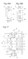
- Figs. 16A and 16B show two methods of winding the first coil 3 around the first stationary member 2 in an actuator according to a fifth embodiment of the present invention.
- This actuator is different from the actuator of the first embodiment in winding of the first coil 3 around the first stationary member 2 and other constructions of this actuator are the same as those of the actuator of the first embodiment.
- the first coil 3 is wound around the central magnetic pole portion 2c of the first stationary member 2 as shown in Fig. 2.
- the first coil 3 is dividedly wound around the opposite magnetic pole portions 2a and 2b of the first stationary member 2 as shown in Fig. 16A.
- these first coils 3 are connected to each other such that the central magnetic pole portion 2c and the opposite magnetic pole portions 2a and 2b are excited to different magnetic poles, respectively.
- effect of thickness of the wound first coil 3 is less than that of the first embodiment in which the first coil 3 is wound around the single magnetic pole portion 2c, so that a space for winding the first coil 3 can be reduced.
- the first coil 3 can also be wound around the magnetic pole portions 2a to 2c of the first stationary member 2 dividedly.
- Fig. 17 shows an actuator according to a sixth embodiment of the present invention.
- This actuator is different from the actuator of the fourth embodiment in provision of a pair of resonant springs 8 and other constructions of this actuator are the same as those of the actuator of the fourth embodiment.
- Each of the resonant springs 8 is formed by a coiled spring and is provided between the casing 1 and the movable member 6 in a deflected state. Namely, one resonant spring 8 is provided between the magnet 6b1 and the corresponding bearing portion 1b and opposite ends of the one resonant spring 8 are, respectively, attached to the magnet 6b1 and the corresponding bearing portion 1b. The other resonant spring 8 is provided between the magnet 6b2 and the corresponding bearing portion 1b and opposite ends of the other resonant spring 8 are, respectively, attached to the magnet 6b2 and the corresponding bearing portion 1b.
- the resonant springs 8 can serve as springs not only for motion of the movable member 6 in the axial direction but for motion of the movable member 6 in the rotational direction.
- the resonant springs 8 have both a function of an axial resonant spring used for resonance in the axial direction and a function of a rotational resonant spring used for resonance in the rotational direction.
- the movable member 6 performs reciprocating motion in the axial direction efficiently on the basis of a resonance phenomenon.
- the movable member 6 performs reciprocating motion efficiently in the rotational direction on the basis of a resonant phenomenon.
- the frequency of the AC voltage applied to each of the first coil 3 and the second coil 5 is set to be close to the resonant frequency because an actual resonant frequency is influenced by an electric circuit for applying the AC voltage to each of the first coil 3 and the second coil 5 so as to deviate slightly from a resonant frequency determined by only a motion system.
- each of the resonant springs 8 has both the functions of the axial resonant spring and the rotational resonant spring.
- the movable member 6 when the AC voltage is applied to the second coil 5 at the frequency close to the resonant frequency determined by the moment of inertia of the movable member 6 and the spring constant of the rotational resonant spring, the movable member 6 is capable of efficiently performing reciprocating motion in the rotational direction at a large amplitude on the basis of the resonant phenomenon. Meanwhile, since each of the resonant springs 8 acts not only as the axial resonant spring but as the rotational resonant spring, a space for providing the resonant springs 8 can be reduced.
- each of the resonant springs 8 has both the functions of the axial resonant spring and the rotational resonant spring has been described here.
- the sixth embodiment is not restricted to this case and thus, the axial resonant spring and the rotational resonant spring may also be provided separately.
- a leaf spring and a spiral spring for example, may be used as the axial resonant spring and the rotational resonant spring, respectively.
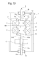
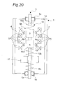
- Figs. 18 to 20 show an actuator according to a seventh embodiment of the present invention.
- This actuator is different from the actuator of the first embodiment in that a further movable member 17 and a spring member 18 are provided so as to be accommodated in the casing 1.
- Other constructions of this actuator are the same as those of the actuator of the first embodiment. Therefore, this actuator operates substantially in the same manner as the actuator of the first embodiment.
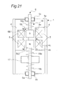
- Fig. 21 showing an actuator which is a modification of the actuator of Fig. 18, the second stationary member 4 is formed into the E-shaped configuration having the three magnetic pole portions, i.e., the opposite magnetic pole portions 4a and 4b and the central magnetic pole portion 4c in the same manner as the modification (Fig. 7) of the first embodiment.
- the further movable member 17 is formed by copper, tungsten, brass or the like into a cylindrical tube having an outside diameter smaller than an inside diameter of the housing portion 1a and a circular through-hole having a diameter larger than that of the shaft 6a is provided at a central axis of the further movable member 17.
- the further movable member 17 is accommodated in the housing portion 1a and is disposed between the magnet 6b2 of the movable member 6 and the corresponding bearing portion 1b so as to be arranged in the axial direction together with the magnet 6b2 such that shaft 6a is inserted through the through-hole.
- the further movable member 17 is supported between the magnet 6b2 and the bearing portion 1b by using the spring member 18 to be described below so as to be moved in the axial direction separately from the movable member 6.
- a mass of the further movable member 17 is so set as to be substantially equal to that of the movable member 6.
- the spring member 18 is constituted by three coiled springs deflectable in the axial direction, namely, a first spring 18a, a second spring 18b and a third spring 18c.
- the first spring 18a is provided between the magnet 6b1 and the corresponding bearing portion 1 b and opposite ends of the first spring 18a are, respectively, attached to the magnet 6b1 and the corresponding bearing portion 1b.
- the second spring 18b is provided between the magnet 6b2 and the further movable member 17 and opposite ends of the second spring 18b are, respectively, attached to the magnet 6b2 and the further movable member 17.
- the third spring 18c is provided between the further movable member 17 and the corresponding bearing portion 1b and opposite ends of the third spring 18c are, respectively, attached to the further movable member 17 and the corresponding bearing portion 1b.
- the spring member 18 acts as a spring also in the rotational direction.
- the casing 1, the movable member 6, the further movable member 17 and the spring member 18 constitute a spring resonant system which performs resonant motion in the axial direction at a resonant frequency determined by respective masses of the casing 1, the movable member 6, the further movable member 17 and the spring member 18 and respective spring constants of the first spring 18a, the second spring 18b and the third spring 18c of the spring member 18.
- This spring resonant system has two resonant frequencies when the spring resonant system can be approximately regarded as being in a state in which the casing 1 is fixed.
- the movable member 6 and the further movable member 17 are moved in the axial direction in an in-phase manner, while at the other resonant frequency (hereinafter, referred to as a "secondary mode resonant frequency"), the movable member 6 and the further movable member 17 are moved in the axial direction in an antiphase manner.
- a primary mode resonant frequency referred to as a "primary mode resonant frequency”
- secondary mode resonant frequency the movable member 6 and the further movable member 17 are moved in the axial direction in an antiphase manner.
- the spring member 18 is the coiled spring, the spring member 18 functions as a spring in the rotational direction by fixing the opposite ends of the spring member 18.
- the casing 1, the movable member 6, the further movable member 17 and the spring member 18 constitute a spring resonant system which performs resonant motion in the radial direction at a resonant frequency determined by respective moments of inertia of the casing 1, the movable member 6, the further movable member 17 and the spring member 18 and respective spring constants of the first spring 18a, the second spring 18b and the third spring 18c of the spring member 18 in the rotational direction. Therefore, if an AC voltage having a frequency close to this resonant frequency is applied to the second coil 5, a large amplitude of the movable member 6 in the rotational direction can be obtained efficiently by the resonant motion in the rotational direction.
- the frequency of the AC voltage applied to each of the first coil 3 and the second coil 5 is set to be close to the resonant frequency in order to perform resonant motion of the movable member 6 in the axial direction and in the rotational direction because an actual resonant frequency is influenced by an electric circuit for applying the AC voltage to each of the first coil 3 and the second coil 5 so as to deviate slightly from a resonant frequency determined by only a motion system.
- the spring resonant system is constituted by the movable member 6, the further movable member 17, the casing 1 and the spring member 18 deflectable among these members in the axial direction
- the magnetic path passing through the first stationary member 2 is excited by the first coil 3 so as to impart to the movable member 6 the force oriented in the axial direction such that resonant motion in the axial direction is performed
- the magnetic path passing through the second stationary member 4 is excited by the second coil 5 so as to impart to the movable member 6 the force oriented in the rotational direction such that resonant motion in the rotational direction is performed
- motion of the movable member 6 in the axial direction and motion of the movable member 6 in the rotational direction can be controlled independently of each other.
- the seventh embodiment a case in which the movable member 6 is subjected to the force oriented in the axial direction from the first stationary member 2 and the force oriented in the rotational direction from the second stationary member 4 has been described.
- the seventh embodiment is not restricted to this case. Since the force oriented in the axial direction and the force oriented in the rotational direction are transmitted from the movable member 6 to the further movable member 17 through the spring member 18, the further movable member 17 may undergo the force oriented in the axial direction from the first stationary member 2 and the force oriented in the rotational direction from the second stationary member 4 by switching magnetic structures of the movable member 6 and the further movable member 17.
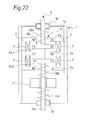
- Fig 22 shows an actuator according to an eighth embodiment of the present invention.
- This actuator is different from the actuator of the seventh embodiment in shape of the movable member 6 and relative position of the movable member 6 and the first stationary member 2 and other constructions of this actuator are the same as those of the actuator of the seventh embodiment. More specifically, this actuator is obtained by applying the shape of the movable member 6 and the relative position of the movable member 6 and the first stationary member 2 in the actuator of the third embodiment of Fig. 13 to the actuator of the seventh embodiment.
- each of the magnets 6b1 and 6b2 forming the driving force generator 6b of the movable member 6 is a cylindrical magnet having a thickness smaller than an axial width of the recesses among the E-shaped magnetic pole portions 2a to 2c of the first stationary member 2 and a diameter of the cylindrical magnet is formed larger than a distance between the corresponding magnetic pole portions of a pair of the first stationary members 2 such that the cylindrical magnet projects into each of the recesses among the magnetic pole portions 2a to 2c of the first stationary member 2.
- radial end portions of the magnets 6b1 and 6b2 of the movable member 6 are rotated so as to traverse the recesses of the first stationary member 2.
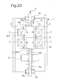
- Fig. 23 shows an actuator according to a ninth embodiment of the present invention.
- This actuator is different from the actuator of the seventh embodiment in shape of the magnets 6b1 and 6b2 of the movable member 6 and other constructions of this actuator are the same as those of the actuator of the seventh embodiment. More specifically, this actuator is obtained by applying the shape of the magnets 6b1 and 6b2 of the movable member 6 in the actuator of the fourth embodiment of Fig. 14 to the actuator of the seventh embodiment.
- the magnets 6b1 and 6b2 of the movable member 6 are cylindrically formed into an identical size such that not only opposed end faces of the magnets 6b1 and 6b2 are brought into contact with each other in the axial direction but the other end faces of the magnets 6b1 and 6b2 opposite to the contacting opposed end faces are flush with axial opposite end faces of the first stationary member 2, respectively.
- the contacting opposed end faces of the magnets 6b1 and 6b2 are disposed at an axial center of the central magnetic pole portion 2c of the first stationary member 2.
- the driving force generator 6b of the movable member 6 includes the two magnets 6b1 and 6b2 held in contact with each other but the magnets 6b1 and 6b2 may also be formed by an integral part having different magnetization directions at its two locations.
- Fig. 24 shows an actuator according to a tenth embodiment of the present invention.
- This actuator is different from the actuator of the ninth embodiment in that the movable member 6 does not undergo force from the second stationary member 4 but the further movable member 17 undergoes force from the second stationary member 4.
- Other constructions of this actuator are the same as those of the actuator of the ninth embodiment.
- the further movable member 17 includes two magnets 17a and 1 7b held in contact with each other in the same manner as the movable member 6 and a circular through-hole having a diameter larger than that of the shaft 6a is formed at a central axis of each of the magnets 17a and 17b.
- the magnets 17a and 17b are accommodated in the housing portion 1a so as to be arranged between the magnet 6b2 of the movable member 6 and the corresponding bearing portion 1b in the axial direction such that the shaft 6a is inserted through the through-hole via a bearing.
- the magnets 17a and 17b are supported between the magnet 6b2 and the corresponding bearing portion 1b by the second spring 18b and the third spring 18c of the spring member 18.
- a total mass of the magnets 17a and 17b of the further movable member 17 is so set as to be substantially equal to the mass of the movable member 6.
- the second stationary member 4 has the same shape as that of the second stationary member 4 of the actuator of the seventh embodiment in Fig. 20 and confronts the further movable member 17.
- the mass of the movable member 6 is so set as to be substantially equal to that of the further movable member 17.
- the seventh and tenth embodiments are not restricted to this setting.
- the mass of the movable member 6 and the mass of the further movable member 17 are adjusted unequally to each other, such effects are gained that vibrations in the axial directions can be lessened and amplitude of reciprocating motion can be adjusted.
- each of the magnets 6b1 and 6b2 of the driving force generator 6b of the movable member 6 is symmetrical with respect to the rotational axis, a pair of the first stationary members 2 disposed symmetrically with respect to the rotational axis are excited in an antiphase manner and a pair of the second stationary members 4 disposed symmetrically with respect to the rotational axis are excited in an antiphase manner.
- the single first stationary member 2 and the single second stationary member 4 may also be provided such that only one of the opposite magnetic poles of each of the magnets 6b1 and 6b2 is used.
- the driving force generator 6b of the movable member 6 includes the two magnets 6b1 and 6b2
- the driving force generator 6b may also be formed by a single magnet.
- the first stationary member 2 has one magnetic portion or two C-shaped magnetic portions and the second stationary member 4 has one magnetic portion
- the movable member 6 can be moved in the axial direction and in the rotational direction.
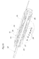
- Figs 25 to 31 show an actuator according to an eleventh embodiment of the present invention.
- This actuator includes an axial actuator 21 used for drive in the axial direction, a rotary actuator 22 used for drive in the rotational direction and a dynamic vibration absorber 23 for lessening vibrations in the axial actuator 21.
- the axial actuator 21, the rotary actuator 22 and the dynamic vibration absorber 23 are mounted on a shaft 25 so as to be accommodated in a casing 27.
- the shaft 25 is, in turn, supported by a pair of bearings 26 provided at opposite end portions of the casing 27, respectively.
- Three springs 24 are, respectively, provided between one of the bearings 26 and the actual actuator 21, between the rotary actuator 22 and the dynamic vibration absorber 23 and between the dynamic vibration absorber 23 and the other bearing 26.
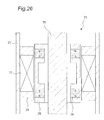
- Fig. 26 shows magnetic structure of the axial actuator 21.
- hatching portions indicate a magnet or magnetic material and blank sections indicate nonmagnetic material.
- the shaft 25 is depicted as magnetic material but is not necessarily required to be made of the magnetic material.
- the axial actuator 21 includes a stationary member 29 having a coil 31 wound therearound and a movable member 28 which has a pair of magnets 30 and is secured to the shaft 25..
- Each of the magnets 30 is magnetized in an upward and downward direction in Fig. 26.
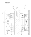
- Fig. 27 shows operating principle of the axial actuator 21.
- Fig. 27 shows operating principle of the axial actuator 21.
- the movable member 28 is displaced upwardly as shown by the arrow.
- the movable member 28 can be driven so as to be displaced in the opposite direction, i. e. , downwardly in Fig. 27.
- An AC voltage of sine wave or cosine wave is applied to the coil 31.
- Fig. 28 show magnetic structure of the rotary actuator 22.
- the rotary actuator 22 includes a stationary member 33 having a coil 34 wound therearound and a movable member 32 which is provided, at its outer periphery, with four magnets 37 as shown in Fig. 29A and is secured to the shaft 25.
- the stationary member 33 includes four upper magnetic poles 35 and four lower magnetic poles 36.
- Figs. 29A and 29B show magnetization states of the upper magnetic poles 35 and the lower magnetic poles 36 of the stationary member 33 of the rotary actuator 22, respectively.
- N-poles and S-poles are, respectively, produced in the upper magnetic poles 35 and the lower magnetic poles 36 and an inner peripheral side and an outer peripheral side of the four magnets 37 are, respectively, magnetized to an S-pole and an N-pole by applying to the coil 34 electric current flowing in one direction
- clockwise torque is produced between the magnets 37 of the movable member 32 and the upper magnetic poles 35 and the lower magnetic poles 36 of the stationary member 33, so that the movable member 32 is rotated clockwise as shown by the arrow.
- the movable member 32 By reversing the magnetization direction based on the electric current inputted to the coil 34, the movable member 32 can be driven so as to be rotated in the opposite direction, i. e. , counterclockwise.
- an AC voltage of sine wave or cosine wave is applied to also the coil 34 of the rotary actuator 22.
- a frequency of the AC voltage applied to the coil 34 of the rotary actuator 22 is set at 1.5 times that of the AC voltage applied to the coil 31 of the axial actuator 21.
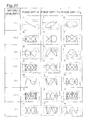
- the shaft 25 can be driven in two directions of the axial direction and the rotational direction by the axial actuator 21 and the rotary actuator 22 as shown in Fig. 31.
- the most left column represents ratio of the frequency fr of the AC voltage applied to the coil 34 of the rotary actuator 22 to the frequency fa of the AC voltage applied to the coil 31 of the axial actuator 21, i.e. , (fr/fa) and a row and a column of each of graphs a) to h) indicate loci of the shaft 25 in the axial direction and in the rotational direction, respectively.
- Fig. 31 the most left column represents ratio of the frequency fr of the AC voltage applied to the coil 34 of the rotary actuator 22 to the frequency fa of the AC voltage applied to the coil 31 of the axial actuator 21, i.e. , (fr/fa) and a row and a column of each of graphs a) to h) indicate loci of the shaft 25 in the axial direction and in the rotational direction, respectively.
- the shaft 25 can be driven along the loci of wider range as shown by the graphs d), f), j), l), p) and r) of Fig. 31.
- the shaft 25 can be driven along the loci of linear motion or complicated elliptic motions as shown by the graphs b), c), g), h), n), o), s) and t) of Fig. 31.
- the shaft 25 can be driven along the various complicated loci.
- the movable member can be moved with great force.
- the space between the first stationary members and the second stationary members becomes large, so that the space for providing the first coil and the second coil can be made large.
- the magnetic pole portions of the first stationary member are disposed at the positions suitable for producing the force oriented in the axial direction when the two magnets of the movable member are positioned so as to confront the first stationary member, so that not only leakage flux is lessened but the movable member can be efficiently moved in the axial direction with great force.
- the magnetic pole portions of the second stationary member are disposed at the positions suitable for producing the force oriented in the rotational direction when the two magnets of the movable member are positioned so as to confront the two magnetic pole portions of the second stationary member, so that not only leakage flux is lessened but the movable member can be efficiently moved in the rotational direction with great force.
- each of the first stationary member and the second stationary member secures the space used as the area for confronting the movable member, so that the area for confrontation between each of the first stationary member and the second stationary member and the movable member can be increased and thus, the large force can be applied to the movable member.
- the gap is formed between the magnetic pole portions of the first stationary member and the magnetic pole portions of the second stationary member, the magnetic reluctance of the magnetic path between the first stationary member and the second stationary member increases, so that the magnetic flux which does not contribute to application of the force to the movable member can be reduced.
- the end portions of the magnets of the movable member are rotated so as to traverse the recesses among the magnetic pole portions of the first stationary member, the area in which the magnetic pole portions of the magnets of the movable member confront the magnetic pole portions of the first stationary member in the axial direction can be increased, so that the movable member can be moved in the axial direction with great force.
- the two magnets of the movable member are formed into an identical size and not only the opposed end faces of the magnets are brought into contact with each other in the axial direction but the other end faces of the magnets opposite to the contacting opposed end faces are flush with the axial opposite end faces of the first stationary member, the position where the other end faces of the magnets are flush with the axial opposite end faces of the first stationary member acts as the stable point.
- the position where the other end faces of the magnets are flush with the axial opposite end faces of the first stationary member acts as the stable point.
- first coil is dividedly wound around the three magnetic pole portions of the first stationary member and the second coil is dividedly wound around the two magnetic pole portions of the second stationary member, effect of thickness of the wound first and second coils is lessened by dividing the first and second coils as compared with a case in which each of the first and second coils is wound around the single magnetic pole portion, so that the space for winding the first and second coils can be reduced.
- the movable member is capable of efficiently performing reciprocating motion in the axial direction at the large amplitude on the basis of the resonance phenomenon when the AC voltage is applied to the first coil at the frequency close to the resonant frequency determined by the mass of the movable member and the spring constant of the axial resonant spring.
- the movable member is capable of efficiently performing reciprocating motion in the rotational direction at the large amplitude on the basis of the resonant phenomenon when the AC voltage is applied to the second coil at the frequency close to the resonant frequency determined by the moment of inertia of the movable member and the spring constant of the rotational resonant spring.
- the single spring member acts not only as the axial resonant spring but as the rotational resonant spring, the space for providing the spring member can be reduced.
- the spring resonant system is constituted by the movable member, the further movable member, the casing and the spring member including the three springs provided among these members and deflectable in the axial direction
- motion of the movable member in the axial direction and motion of the movable member in the rotational direction can be controlled independently of each other.
- the movable member and the further movable member can be, respectively, moved oppositely in the axial direction, it is possible to lessen the vibrations due to the axial inertia force.
- the first stationary member and the second stationary member imparts to one of the movable member and the further movable member the force oriented in the axial direction and the force oriented in the rotational direction, respectively, the other of the movable member and the further movable member does not undergo the forces from the first stationary member and the second stationary member, so that design of the spring resonant system is facilitated.
- the magnetic path for generating the force oriented in the axial direction and the magnetic path for generating the force oriented in the rotational direction are separated from each other, so that the magnetic circuit can be designed easily.
- one of the movable member and the further movable member which undergoes the forces from the first stationary member and the second stationary member, includes the magnet which has the magnetization direction substantially orthogonal to the axial direction and is provided symmetrically with respect to the rotational axis and the first stationary members and the second stationary members are, respectively, provided symmetrically with respect to the rotational axis, the first stationary member and the second stationary member impart to the one of the movable member and the further movable member the force oriented in the axial direction and the force oriented in the rotational direction, so that the spring resonant system can be moved with great force.
- one of the movable member and the further movable member, which undergoes the force oriented in the axial direction from the first stationary member includes the two magnets having the opposite magnetization directions, respectively and the first stationary member has the three E-shaped magnetic pole portions, the magnetic pole portions of the first stationary member are disposed at the positions suitable for producing the force oriented in the axial direction when the two magnets are positioned so as to confront the first stationary member, so that not only leakage flux is lessened but the spring resonant system can be efficiently moved in the axial direction with great force.
- one of the movable member and the further movable member which undergoes the force oriented in the rotational direction from the second stationary member, includes the two magnets having the opposite magnetization directions, respectively and the second stationary member has the two C-shaped magnetic pole portions
- the magnetic pole portions of the second stationary member are disposed at the positions suitable for producing the force oriented in the rotational direction when the two magnets are positioned so as to confront the two magnetic pole portions of the second stationary member, so that not only leakage flux is lessened but the one of the movable member and the further movable member can be efficiently moved in the rotational direction with great force.
- the end portions of the magnets are rotated so as to traverse the recesses among the magnetic pole portions of the first stationary member, the area in which the magnetic pole portions of the magnets confront the magnetic pole portions of the first stationary member in the axial direction can be increased, so that the spring resonant system can be moved in the axial direction with great force.
Landscapes
- Engineering & Computer Science (AREA)
- Power Engineering (AREA)
- Reciprocating, Oscillating Or Vibrating Motors (AREA)
Applications Claiming Priority (5)
| Application Number | Priority Date | Filing Date | Title |
|---|---|---|---|
| JP2002342760 | 2002-11-26 | ||
| JP2002342761 | 2002-11-26 | ||
| JP2002342760 | 2002-11-26 | ||
| JP2002342761 | 2002-11-26 | ||
| PCT/JP2003/014987 WO2004049547A1 (ja) | 2002-11-26 | 2003-11-25 | アクチュエータ |
Publications (2)
| Publication Number | Publication Date |
|---|---|
| EP1566879A1 true EP1566879A1 (de) | 2005-08-24 |
| EP1566879A4 EP1566879A4 (de) | 2008-07-09 |
Family
ID=32396269
Family Applications (1)
| Application Number | Title | Priority Date | Filing Date |
|---|---|---|---|
| EP03774196A Withdrawn EP1566879A4 (de) | 2002-11-26 | 2003-11-25 | Betütigungsglied |
Country Status (5)
| Country | Link |
|---|---|
| US (2) | US7218018B2 (de) |
| EP (1) | EP1566879A4 (de) |
| AU (1) | AU2003284670A1 (de) |
| CA (1) | CA2493603C (de) |
| WO (1) | WO2004049547A1 (de) |
Cited By (5)
| Publication number | Priority date | Publication date | Assignee | Title |
|---|---|---|---|---|
| WO2007020599A3 (en) * | 2005-08-16 | 2007-06-07 | Koninkl Philips Electronics Nv | Resonant actuator for a personal care appliance having a programmable actuation capability |
| WO2008055866A1 (de) | 2006-11-07 | 2008-05-15 | Siemens Aktiengesellschaft | Dreh-hub-motor und bestückkopf |
| WO2010109407A1 (en) * | 2009-03-27 | 2010-09-30 | Koninklijke Philips Electronics N.V. | Motor for linear and rotary movement |
| WO2013088235A1 (fr) * | 2011-12-16 | 2013-06-20 | F.Q.N.K. | Actionneur electromagnétique |
| CN106369209A (zh) * | 2016-09-06 | 2017-02-01 | 中国矿业大学 | 一种矿井瓦斯抽采管道智能阀门装置 |
Families Citing this family (34)
| Publication number | Priority date | Publication date | Assignee | Title |
|---|---|---|---|---|
| AU2003284670A1 (en) * | 2002-11-26 | 2004-06-18 | Matsushita Electric Works, Ltd. | Actuator |
| DE10355446A1 (de) | 2003-11-27 | 2005-06-30 | Braun Gmbh | Elektromotor für ein elektrisches Kleingerät |
| US8795028B2 (en) * | 2004-10-04 | 2014-08-05 | The Gleason Works | Magnetic spindle for machine tool |
| GB2423641A (en) * | 2005-02-23 | 2006-08-30 | Noside Ltd | Rotary and linear electromagnetic reciprocating machine |
| CN101282677B (zh) * | 2005-10-05 | 2010-07-28 | 奥林巴斯医疗株式会社 | 胶囊式医疗装置、其引导系统和引导方法、及被检体内插入装置 |
| US20070236577A1 (en) * | 2006-03-30 | 2007-10-11 | Chau-Yaun Ke | Systems and methods for providing image stabilization |
| CN101248570A (zh) * | 2006-09-14 | 2008-08-20 | 冈本范政 | 发电机 |
| WO2008105393A1 (ja) * | 2007-02-26 | 2008-09-04 | Olympus Medical Systems Corp. | 磁気アクチュエータ、磁気アクチュエータの動作方法、およびこれを用いたカプセル型内視鏡 |
| US7898120B2 (en) * | 2007-05-31 | 2011-03-01 | The Boeing Company | Linear-rotary actuators and actuator systems |
| EP2308167B1 (de) * | 2008-04-22 | 2016-11-09 | Orange | Tragbare mechatronische anordnung zur erzeugung von elektrischem strom |
| CN102202600B (zh) * | 2008-10-31 | 2014-09-03 | 三美电机株式会社 | 驱动器以及使用该驱动器的电动牙刷 |
| JP5176891B2 (ja) * | 2008-11-14 | 2013-04-03 | ミツミ電機株式会社 | アクチュエータ及びこれを用いた電動歯ブラシ |
| ES2549982T3 (es) * | 2009-06-12 | 2015-11-03 | Braun Gmbh | Motor eléctrico para un aparato eléctrico pequeño |
| KR100964538B1 (ko) * | 2009-09-25 | 2010-06-21 | 김홍중 | 선형 전동기 |
| US8418302B1 (en) * | 2010-06-23 | 2013-04-16 | Chi Ming Suen | Tooth brush motor |
| ES2693620T3 (es) * | 2012-07-13 | 2018-12-13 | Braun Gmbh | Motor lineal y dispositivo eléctrico con motor lineal |
| EP2792299B1 (de) * | 2012-07-20 | 2018-09-26 | Kyushu Institute of Technology | Vorrichtung mit einer beweglichen kapsel |
| DE102012107014A1 (de) * | 2012-08-01 | 2014-02-06 | Eto Magnetic Gmbh | Aktuatorvorrichtung |
| JP5842789B2 (ja) * | 2012-11-01 | 2016-01-13 | ミツミ電機株式会社 | アクチュエータ及び電動理美容器具 |
| EP3389801A4 (de) * | 2015-12-14 | 2019-07-10 | Indian Industries, Inc. | Basketballtor mit schwingungsdämpfung |
| CN106451990A (zh) * | 2016-11-02 | 2017-02-22 | 深圳市兆业电子科技有限公司 | 一种永磁直线电机及直线振动器 |
| CN110719762B (zh) * | 2017-05-09 | 2022-06-03 | 皇家飞利浦有限公司 | 个人护理清洁设备和振动消除悬架 |
| US10222863B1 (en) * | 2017-09-05 | 2019-03-05 | Apple Inc. | Linear haptic actuator including field members and biasing members and related methods |
| JP7188851B2 (ja) * | 2018-08-29 | 2022-12-13 | ミネベアミツミ株式会社 | 振動アクチュエータ、及びこれを備える携帯型電子機器 |
| DE102018217513A1 (de) * | 2018-10-12 | 2020-04-16 | Festo Se & Co. Kg | Linearreluktanzmotor |
| CN109253344A (zh) * | 2018-11-29 | 2019-01-22 | 湖北科技学院 | 一种管道爬行机器人上的驱动机构 |
| KR102177140B1 (ko) * | 2019-01-18 | 2020-11-10 | 효성중공업 주식회사 | 액츄에이터 |
| DE202019105129U1 (de) * | 2019-09-17 | 2020-12-23 | nui lab GmbH | Elektromagnetischer Aktuator |
| CN110729845B (zh) * | 2019-10-17 | 2025-09-09 | 深圳市万至达电机制造有限公司 | 一种用于纹身纹绣的直线运动电机 |
| WO2021092404A1 (en) * | 2019-11-06 | 2021-05-14 | Positive Energy, a Gravity and Motion Company, Inc. | Methods and apparatus for kinetic energy harvesting |
| US11437886B2 (en) | 2019-11-06 | 2022-09-06 | Positive Energy, a Gravity and Motion Company, Inc. | Methods and apparatus for kinetic energy harvesting |
| WO2021252731A1 (en) | 2020-06-11 | 2021-12-16 | Andis Company | Hair clipper with linear actuator |
| US11573636B2 (en) | 2020-06-29 | 2023-02-07 | Apple Inc. | Haptic actuator including permanent magnet having a non-vertical, magnetic polarization transition zone and related methods |
| US12212208B2 (en) | 2020-06-29 | 2025-01-28 | Apple Inc. | Haptic actuator including a field member having an opening receiving a stator therein and related methods |
Family Cites Families (37)
| Publication number | Priority date | Publication date | Assignee | Title |
|---|---|---|---|---|
| US78310A (en) * | 1868-05-26 | Improvement in permutation-looks | ||
| US43016A (en) * | 1864-06-07 | Improved method of suspending steam-boilers | ||
| US275484A (en) * | 1883-04-10 | William haas | ||
| US40052A (en) * | 1863-09-22 | Improvement in corn-shellers | ||
| US128859A (en) * | 1872-07-09 | Improvement in stove-dampers | ||
| US4575A (en) * | 1846-06-16 | Machinery for cu i | ||
| US199689A (en) * | 1878-01-29 | Improvement in sulky-plows | ||
| US130221A (en) * | 1872-08-06 | Improvement in railway switches | ||
| US214765A (en) * | 1879-04-29 | Improvement in machines for cleaning coffee | ||
| US195884A (en) * | 1877-10-09 | Improvement in cotton-batting-folding machines | ||
| US47670A (en) * | 1865-05-09 | Air-tight coal-stove | ||
| US3453510A (en) * | 1964-04-30 | 1969-07-01 | Robertshaw Controls Co | Linear and rotary direct current stepping motors and control system |
| US3394295A (en) * | 1965-10-04 | 1968-07-23 | Itt | Rotating and reciprocating electric motor |
| US3538017A (en) * | 1966-10-26 | 1970-11-03 | Sir Soc Italiana Resine Spa | Processing spent catalysts |
| US3851196A (en) * | 1971-09-08 | 1974-11-26 | Xynetics Inc | Plural axis linear motor structure |
| JPS51125814A (en) * | 1975-04-24 | 1976-11-02 | Citizen Watch Co Ltd | Printer-driving composite pulse motor |
| FR2348595A1 (fr) * | 1976-04-15 | 1977-11-10 | Anvar | Moteur hybride tournant-lineaire |
| US4607197A (en) * | 1978-04-17 | 1986-08-19 | Imc Magnetics Corporation | Linear and rotary actuator |
| US4281263A (en) * | 1978-05-23 | 1981-07-28 | Gradient | Hybrid stator and a two-axis induction electric motor constructed therewith |
| US4234831A (en) * | 1978-07-18 | 1980-11-18 | Josef Kemmer | Compound rotary and/or linear motor |
| JPS60128859A (ja) * | 1983-12-15 | 1985-07-09 | Yokogawa Hokushin Electric Corp | 駆動装置 |
| JPS61214765A (ja) * | 1985-03-18 | 1986-09-24 | Hisashi Tamura | 回転軸が往復運動する電動機 |
| JPS6240052A (ja) * | 1985-08-14 | 1987-02-21 | Tokyo R & D:Kk | 回転及び軸直線運動両用型の電動機 |
| DE3538017A1 (de) | 1985-10-25 | 1987-04-30 | Triumph Adler Ag | Elektrischer antrieb |
| US5093596A (en) * | 1990-10-24 | 1992-03-03 | Ibm Corporation | Combined linear-rotary direct drive step motor |
| JP3600654B2 (ja) * | 1995-03-28 | 2004-12-15 | オリエンタルモーター株式会社 | リニア・ロータリ複合型ステッピングモータ |
| US5952744A (en) * | 1996-03-28 | 1999-09-14 | Anoiad Corporation | Rotary-linear actuator |
| JP2000004575A (ja) | 1998-04-13 | 2000-01-07 | Hitachi Metals Ltd | リニア駆動アクチュエ―タ |
| US6429611B1 (en) * | 2000-01-28 | 2002-08-06 | Hui Li | Rotary and linear motor |
| KR100352937B1 (ko) | 2000-05-20 | 2002-09-16 | 미래산업 주식회사 | 회전 및 직선운동형 선형전동기 |
| JP3470689B2 (ja) | 2000-08-28 | 2003-11-25 | 松下電工株式会社 | リニアアクチュエータ |
| JP3475949B2 (ja) | 2000-09-29 | 2003-12-10 | 松下電工株式会社 | リニアオシレータ |
| US6873067B2 (en) * | 2000-09-29 | 2005-03-29 | Matsushita Electric Works, Ltd. | Linear oscillator |
| US6611074B2 (en) * | 2001-04-12 | 2003-08-26 | Ballado Investments Inc. | Array of electromagnetic motors for moving a tool-carrying sleeve |
| US6798087B1 (en) * | 2002-01-08 | 2004-09-28 | Anorad Corporation | Rotary-linear actuator system, method of manufacturing and method of using a rotary-linear actuator |
| JP4206735B2 (ja) | 2002-11-26 | 2009-01-14 | パナソニック電工株式会社 | 電動ハブラシ |
| AU2003284670A1 (en) * | 2002-11-26 | 2004-06-18 | Matsushita Electric Works, Ltd. | Actuator |
-
2003
- 2003-11-25 AU AU2003284670A patent/AU2003284670A1/en not_active Abandoned
- 2003-11-25 CA CA002493603A patent/CA2493603C/en not_active Expired - Fee Related
- 2003-11-25 EP EP03774196A patent/EP1566879A4/de not_active Withdrawn
- 2003-11-25 US US10/518,547 patent/US7218018B2/en not_active Expired - Fee Related
- 2003-11-25 WO PCT/JP2003/014987 patent/WO2004049547A1/ja not_active Ceased
-
2007
- 2007-04-02 US US11/695,283 patent/US20070170877A1/en not_active Abandoned
Cited By (10)
| Publication number | Priority date | Publication date | Assignee | Title |
|---|---|---|---|---|
| WO2007020599A3 (en) * | 2005-08-16 | 2007-06-07 | Koninkl Philips Electronics Nv | Resonant actuator for a personal care appliance having a programmable actuation capability |
| WO2008055866A1 (de) | 2006-11-07 | 2008-05-15 | Siemens Aktiengesellschaft | Dreh-hub-motor und bestückkopf |
| WO2010109407A1 (en) * | 2009-03-27 | 2010-09-30 | Koninklijke Philips Electronics N.V. | Motor for linear and rotary movement |
| CN102365811A (zh) * | 2009-03-27 | 2012-02-29 | 皇家飞利浦电子股份有限公司 | 用于线性和旋转运动的马达 |
| CN102365811B (zh) * | 2009-03-27 | 2013-12-11 | 皇家飞利浦电子股份有限公司 | 用于线性和旋转运动的马达 |
| US8841869B2 (en) | 2009-03-27 | 2014-09-23 | Koninklijke Philips N.V. | Motor for linear and rotary movement |
| WO2013088235A1 (fr) * | 2011-12-16 | 2013-06-20 | F.Q.N.K. | Actionneur electromagnétique |
| FR2984633A1 (fr) * | 2011-12-16 | 2013-06-21 | F Q N K | Actionneur electromagnetique |
| CN106369209A (zh) * | 2016-09-06 | 2017-02-01 | 中国矿业大学 | 一种矿井瓦斯抽采管道智能阀门装置 |
| CN106369209B (zh) * | 2016-09-06 | 2019-05-03 | 中国矿业大学 | 一种矿井瓦斯抽采管道智能阀门装置 |
Also Published As
| Publication number | Publication date |
|---|---|
| EP1566879A4 (de) | 2008-07-09 |
| US20050200207A1 (en) | 2005-09-15 |
| CA2493603C (en) | 2009-10-06 |
| US20070170877A1 (en) | 2007-07-26 |
| WO2004049547A1 (ja) | 2004-06-10 |
| US7218018B2 (en) | 2007-05-15 |
| CA2493603A1 (en) | 2004-06-10 |
| AU2003284670A1 (en) | 2004-06-18 |
Similar Documents
| Publication | Publication Date | Title |
|---|---|---|
| CA2493603C (en) | Actuator capable of moving in axial and rotational directions | |
| JP4039359B2 (ja) | アクチュエータ | |
| JP4400463B2 (ja) | 振動型リニアアクチュエータ及びこれを用いた電動歯ブラシ | |
| KR100722830B1 (ko) | 왕복 직선구동 및 롤링 구동이 가능한 액츄에이터 및 그것을 사용한 전동칫솔 | |
| JP5248598B2 (ja) | 機械的振動エネルギーを電気エネルギーに変換するための永久磁石による発電機 | |
| EP1626483B1 (de) | Hin und her gehendes lineares antriebsbetätigungselement und elektrische zahnbürste | |
| KR100753067B1 (ko) | 롤링 구동 액츄에이터 및 그것을 사용한 전동칫솔 | |
| US7449803B2 (en) | Electromagnetic motor to create a desired low frequency vibration or to cancel an undesired low frequency vibration | |
| JP4725910B2 (ja) | リニアアクチュエータ | |
| JP3412511B2 (ja) | リニアアクチュエータ | |
| JP2009060785A (ja) | 反対位相の2個の可動部品を備えた電磁アクチュエータ | |
| US20060255664A1 (en) | Drive unit generating an oscillatory motion for small electrical appliances | |
| JPH0528066B2 (de) | ||
| JP2001520499A (ja) | リニア運動を発生する電磁装置 | |
| CN100536293C (zh) | 执行元件 | |
| JP2010035315A (ja) | アクチュエータ | |
| US10715022B2 (en) | Actuator and electric beauty device | |
| KR101632937B1 (ko) | 진동발생장치 | |
| KR20150142519A (ko) | 진동발생장치 | |
| RU2098909C1 (ru) | Электромеханический привод | |
| JP5237784B2 (ja) | アクチュエータ | |
| KR20030020787A (ko) | 기동자석형 vcm을 이용한 정밀 액츄에이터스테이지장치 | |
| JPH1019936A (ja) | 交差コイル型指示計器 | |
| JP2004153908A (ja) | アクチュエータ | |
| JP2007037261A (ja) | 電磁アクチュエータ |
Legal Events
| Date | Code | Title | Description |
|---|---|---|---|
| PUAI | Public reference made under article 153(3) epc to a published international application that has entered the european phase |
Free format text: ORIGINAL CODE: 0009012 |
|
| 17P | Request for examination filed |
Effective date: 20050106 |
|
| AK | Designated contracting states |
Kind code of ref document: A1 Designated state(s): AT BE BG CH CY CZ DE DK EE ES FI FR GB GR HU IE IT LI LU MC NL PT RO SE SI SK TR |
|
| AX | Request for extension of the european patent |
Extension state: AL LT LV MK |
|
| DAX | Request for extension of the european patent (deleted) | ||
| RBV | Designated contracting states (corrected) |
Designated state(s): DE FR GB IT |
|
| A4 | Supplementary search report drawn up and despatched |
Effective date: 20080606 |
|
| 17Q | First examination report despatched |
Effective date: 20081222 |
|
| RAP1 | Party data changed (applicant data changed or rights of an application transferred) |
Owner name: PANASONIC ELECTRIC WORKS CO., LTD. |
|
| REG | Reference to a national code |
Ref country code: DE Ref legal event code: R079 Free format text: PREVIOUS MAIN CLASS: H02K0033020000 Ipc: H02K0033160000 |
|
| RIC1 | Information provided on ipc code assigned before grant |
Ipc: H02K 33/16 20060101AFI20110524BHEP |
|
| GRAP | Despatch of communication of intention to grant a patent |
Free format text: ORIGINAL CODE: EPIDOSNIGR1 |
|
| RAP1 | Party data changed (applicant data changed or rights of an application transferred) |
Owner name: PANASONIC CORPORATION |
|
| STAA | Information on the status of an ep patent application or granted ep patent |
Free format text: STATUS: THE APPLICATION IS DEEMED TO BE WITHDRAWN |
|
| 18D | Application deemed to be withdrawn |
Effective date: 20120411 |